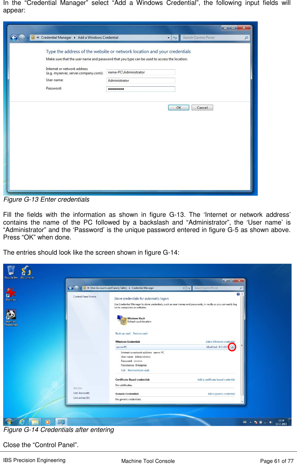
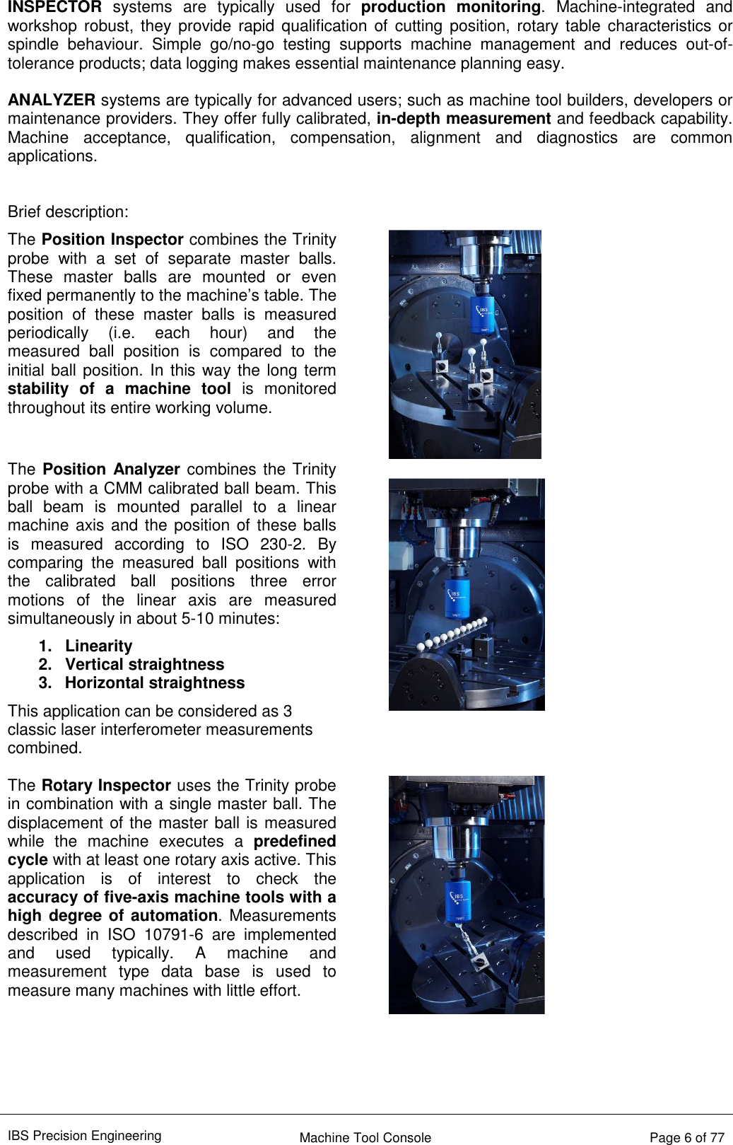
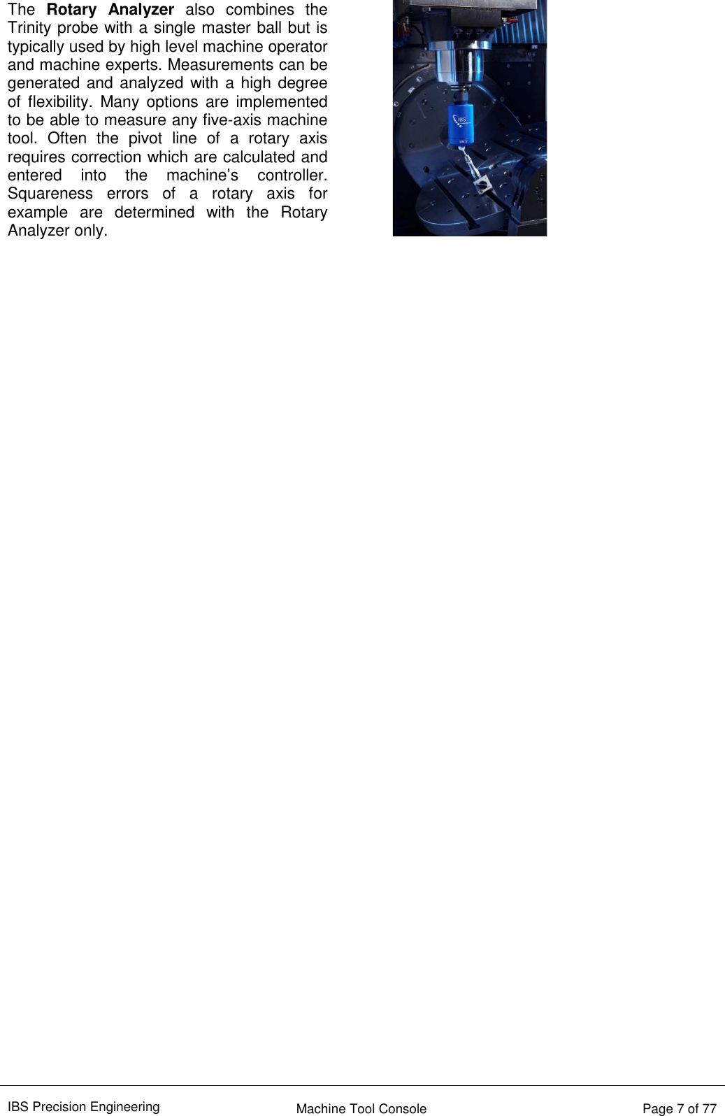
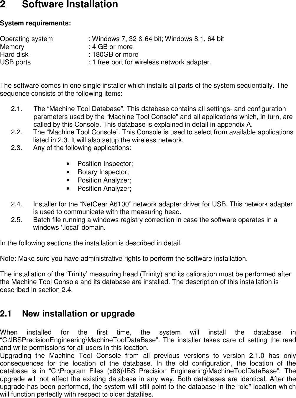
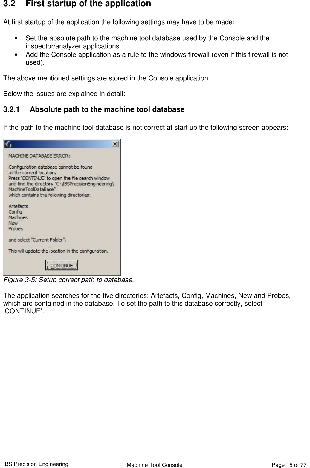
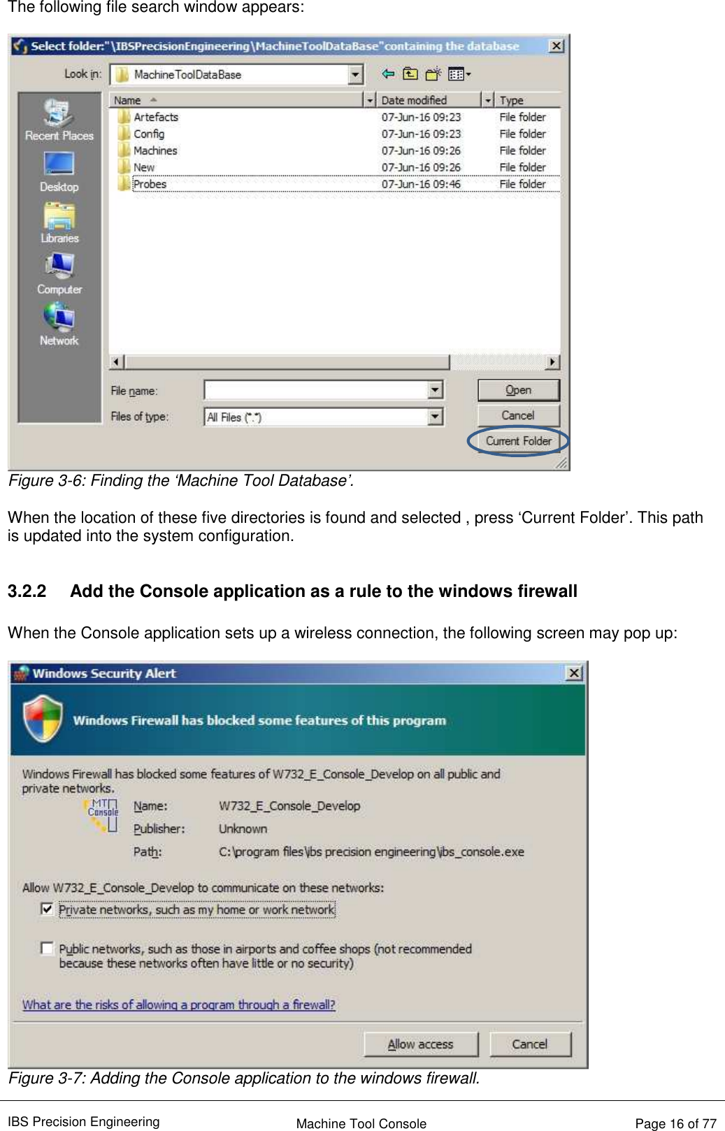
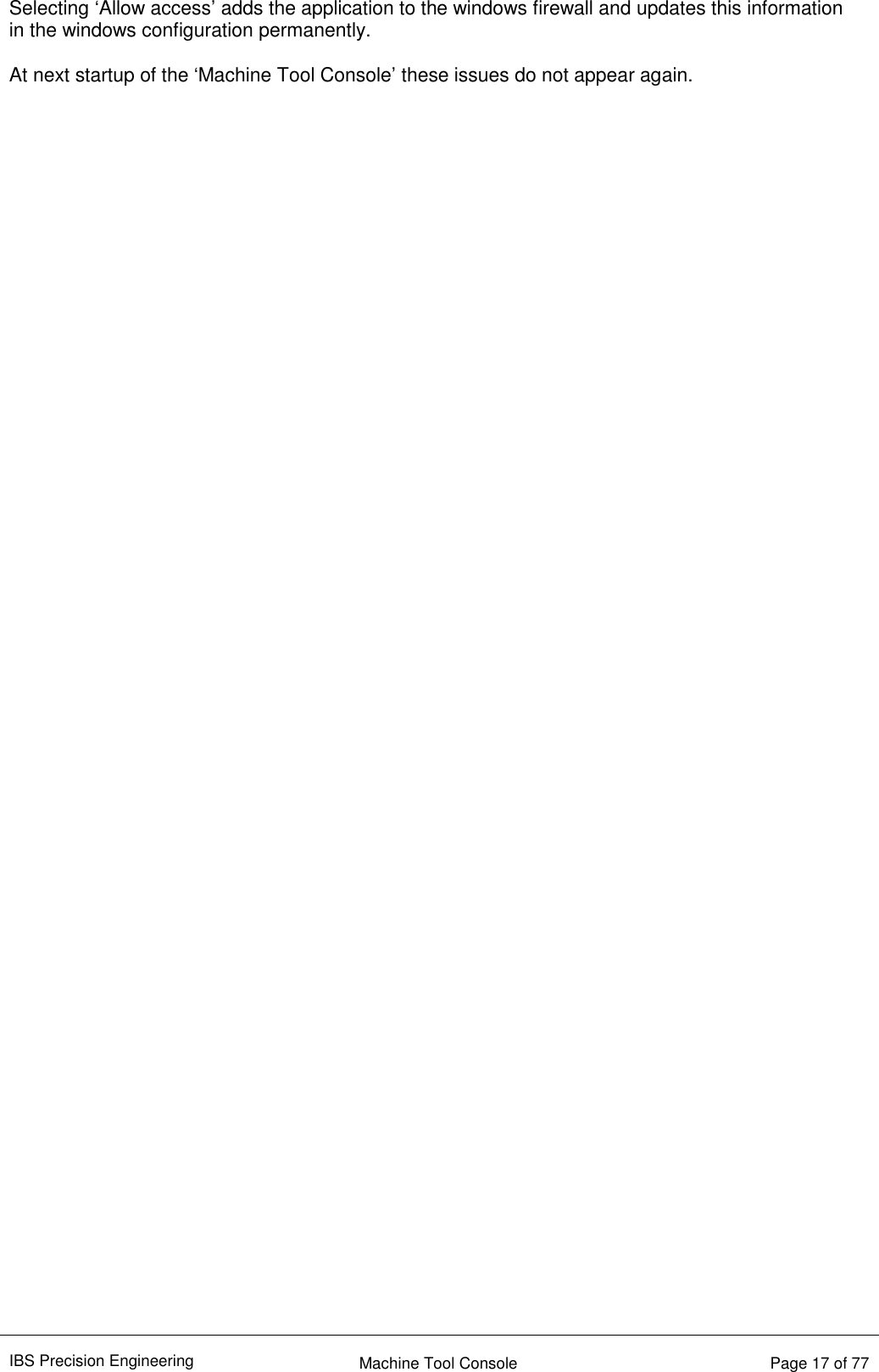
IBS Precision Engineering TRINITY Trinity Wireless Probe User Manual Machine Tool Console Users Manual Aug 2016
IBS Precision Engineering BV Trinity Wireless Probe Machine Tool Console Users Manual Aug 2016
UserManual.wiki
>
IBS Precision Engineering
>
TRINITY User Manual
Users Manual
Navigation menu
Upload a User Manual
Namespaces
Wiki Guide
HTML
PDF
Info
Views
User Manual
Discussion / Help
Navigation
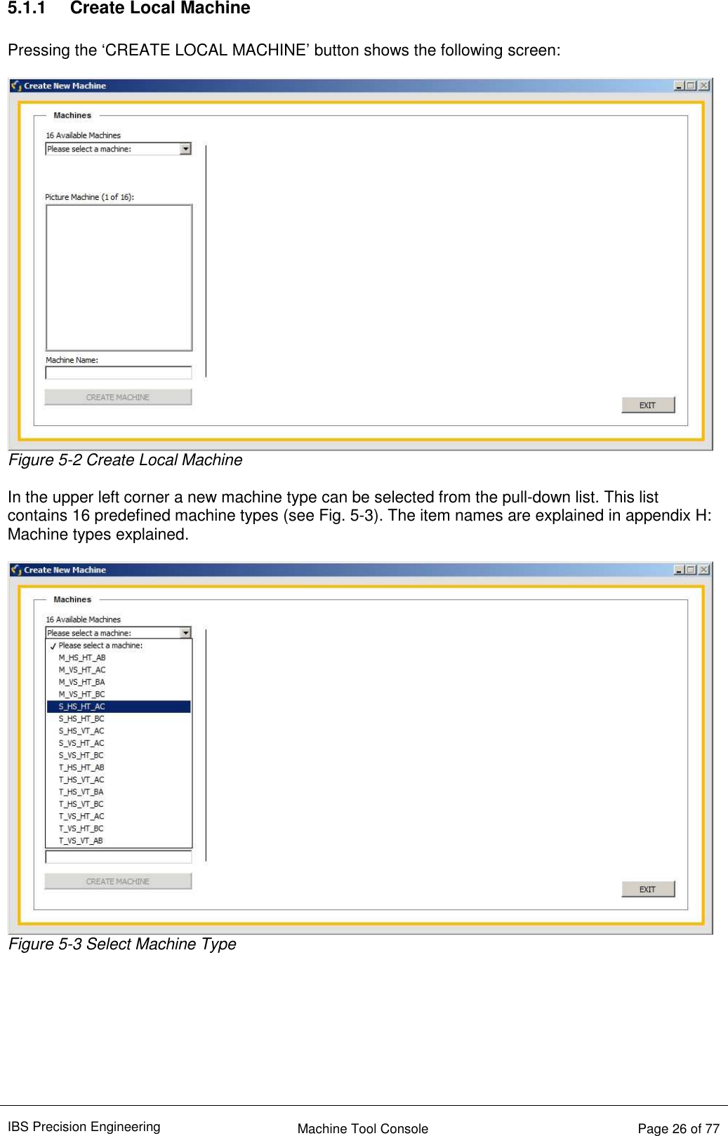
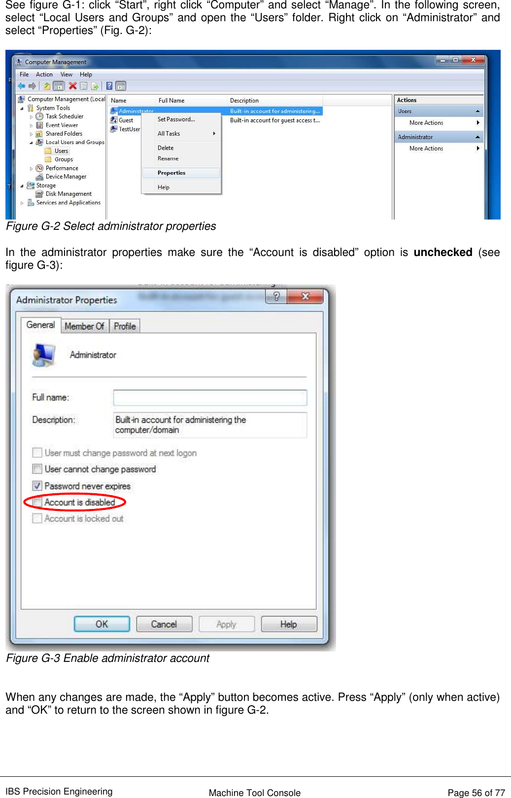
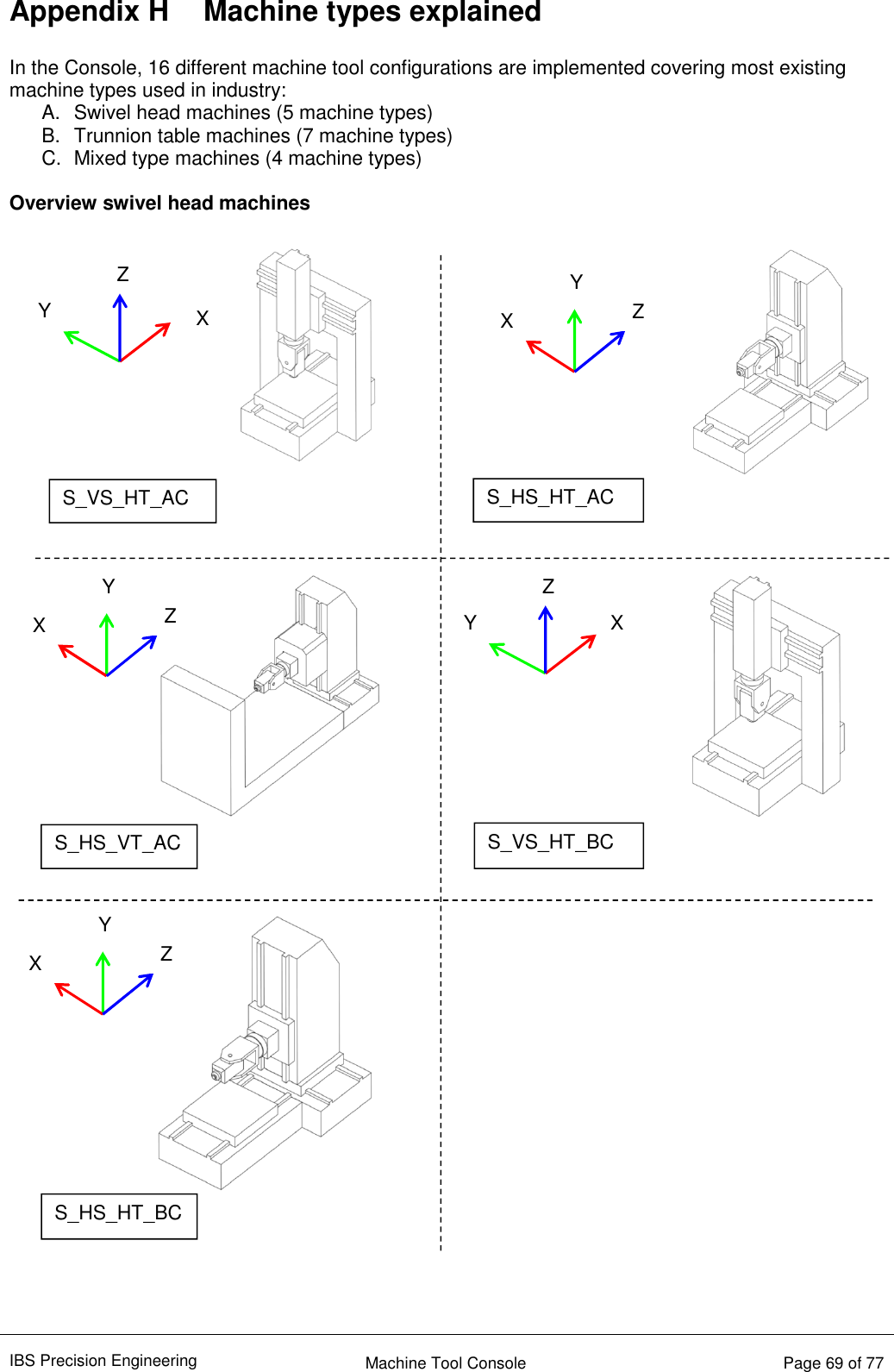
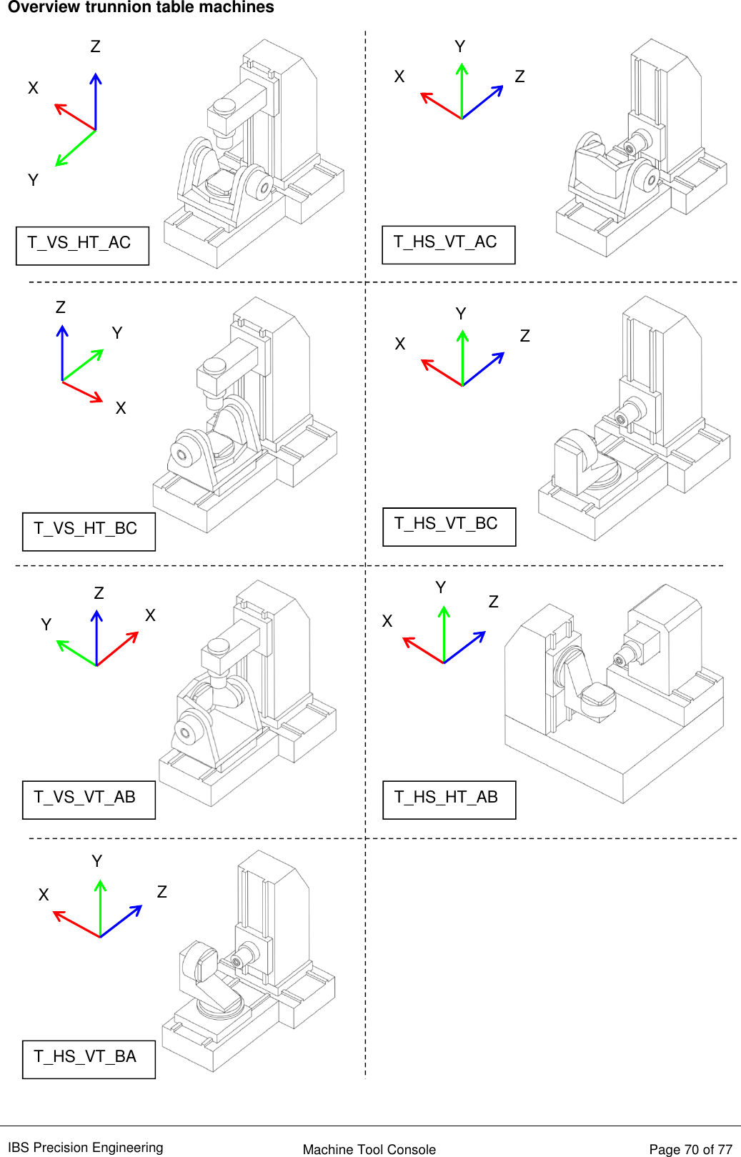
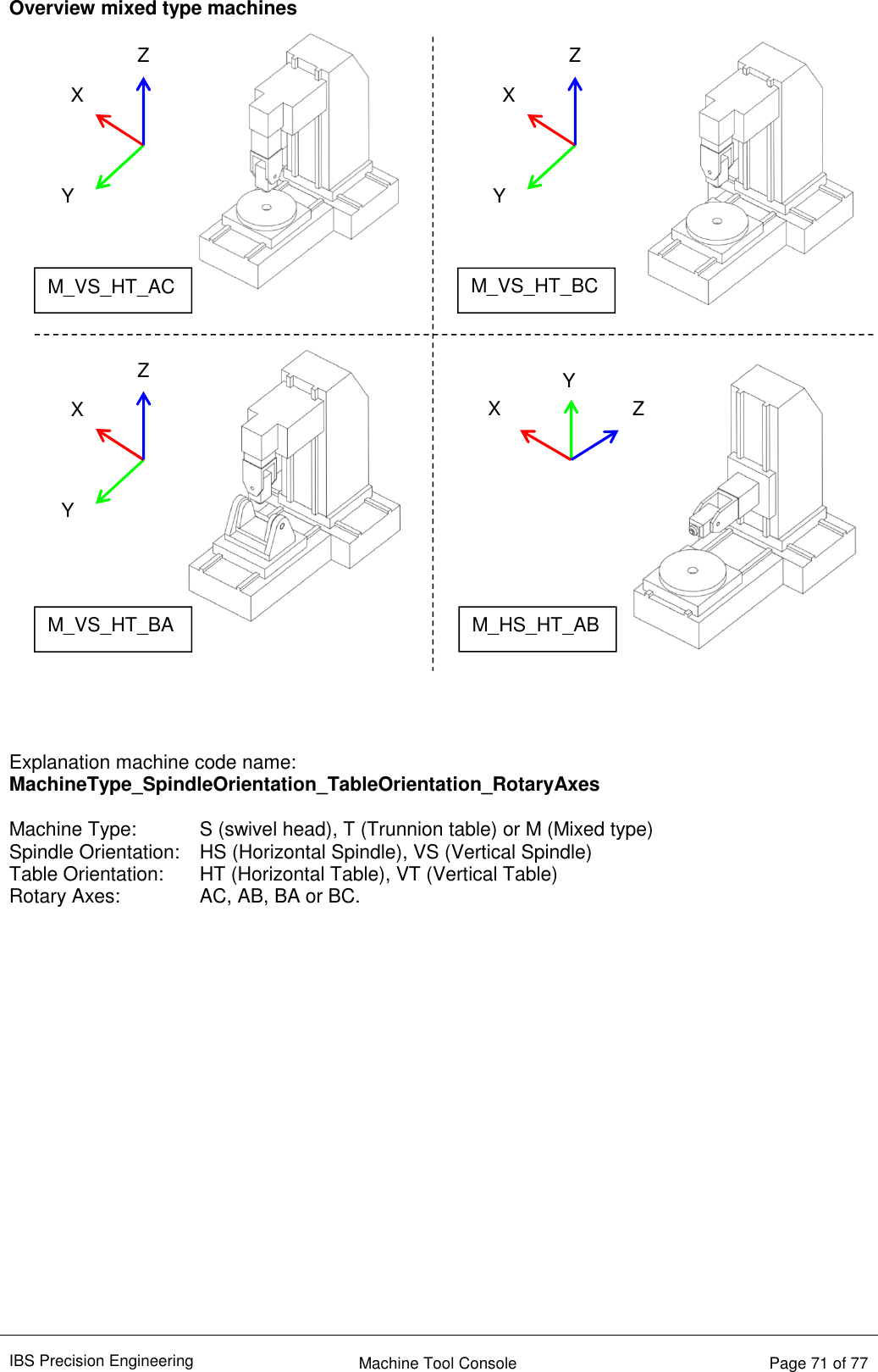
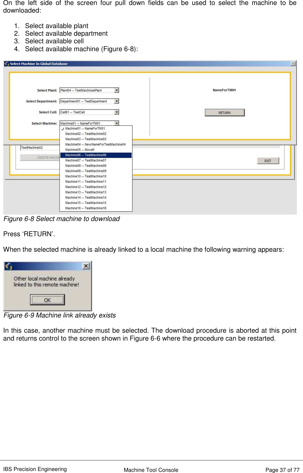
![IBS Precision Engineering Machine Tool Console Page 29 of 77 5.2 Parameter settings In this section the parameter settings for each of the inspector applications are explained. These parameters can also be set during the creation of a local machine. 5.2.1 Parameter setting for “Position Inspector” When ‘EDIT LOCAL MACHINE’ is pressed as described in section 5.1.2, a machine is selected and ‘EDIT MACHINE’ is pressed, the following screen appears for the Position Inspector: Figure 5-8 Parameters for Position Inspector • Machine parameters for “Position Inspector” • Measurement type parameters for “Position Inspector” Parameter name Explanation Time to wait (After Vibration) [s] When the vibration level criterion is met after positioning the measuring head on the artefact ball, the system waits the amount of seconds set with this parameter before a measurement point is taken. Trigger Level [V] Measurement of the vibration level criterion is triggered when all three sensors of the measuring head measure below the voltage set with this parameter. Vibration Level [µm] When the measuring head is positioned on the artefact ball, the residual system vibration may not exceed the value set with this parameter. Deviation Tolerance X-axis [µm] With this parameter the maximum deviation with respect to the reference run results is set for the X-axis. See Figure 5-9. Deviation Tolerance Y-axis [µm] With this parameter the maximum deviation with respect to the reference run results is set for the Y-axis. See Figure 5-9. Deviation Tolerance Z-axis [µm] With this parameter the maximum deviation with respect to the reference run results is set for the Z-axis. See Figure 5-9.](https://usermanual.wiki/IBS-Precision-Engineering/TRINITY/User-Guide-3128935-Page-29.png)
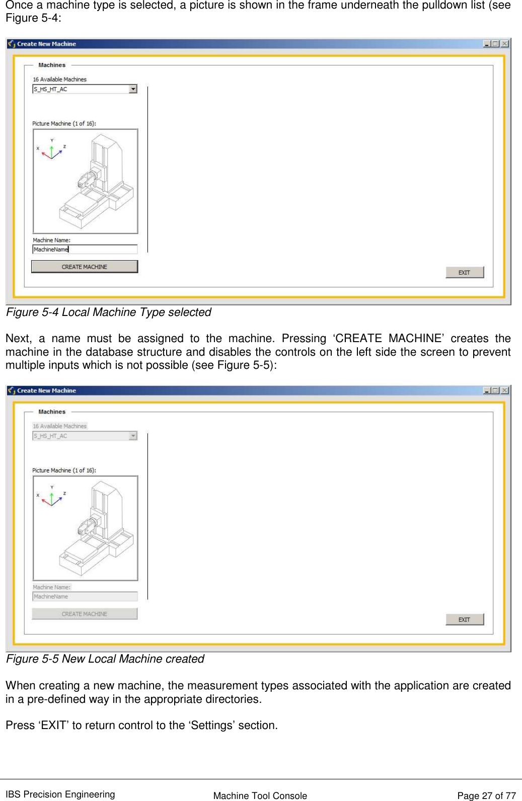
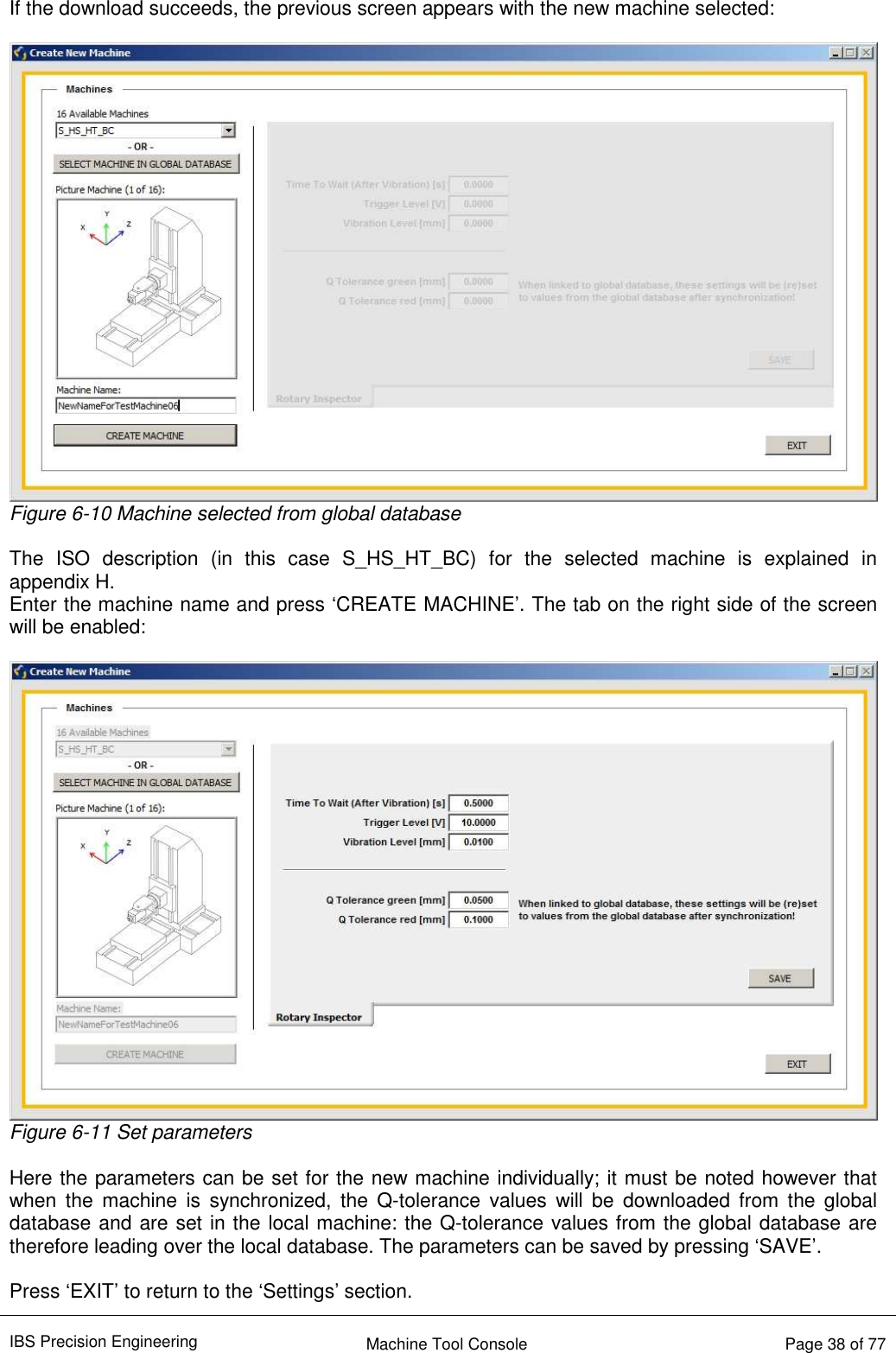
![IBS Precision Engineering Machine Tool Console Page 31 of 77 5.2.2 Parameter setting for “Rotary Inspector” When ‘EDIT LOCAL MACHINE’ is pressed as described in section 5.1.2, a machine is selected and ‘EDIT MACHINE’ is pressed, the following screen appears for the Rotary Inspector: Figure 5-10 Parameters for Rotary Inspector Parameter name Explanation Time to wait (After Vibration) [s] When the vibration level criterion is met after positioning the measuring head on the artefact ball, the system waits the amount of seconds set with this parameter before a measurement point is taken. Trigger Level [V] Measurement of the vibration level criterion is triggered when all three sensors of the measuring head measure below the voltage set with this parameter. Vibration Level [µm] When the measuring head is positioned on the artefact ball, the residual system vibration may not exceed the value set with this parameter. Q Tolerance green [mm] This level represents the lower limit of the Q-value, the meaning of this value is explained in the Rotary Inspector user manual section 3.1. Q Tolerance red [mm] This level represents the upper limit of the Q-value, the meaning of this value is explained in the Rotary Inspector user manual section 3.1. Note that when the Rotary Inspector is used in conjunction with the Rotary Inspector Data Manager, both Q tolerance values are overwritten by the values saved for this machine in the global database when: 1. The local machine is linked to a machine in the global database 2. Both machines are synchronized Synchronization will be explained in section 6. Press ‘SAVE’ to save the values in the database. Press ‘EXIT’ to return control to the ‘SETTINGS’ section.](https://usermanual.wiki/IBS-Precision-Engineering/TRINITY/User-Guide-3128935-Page-31.png)

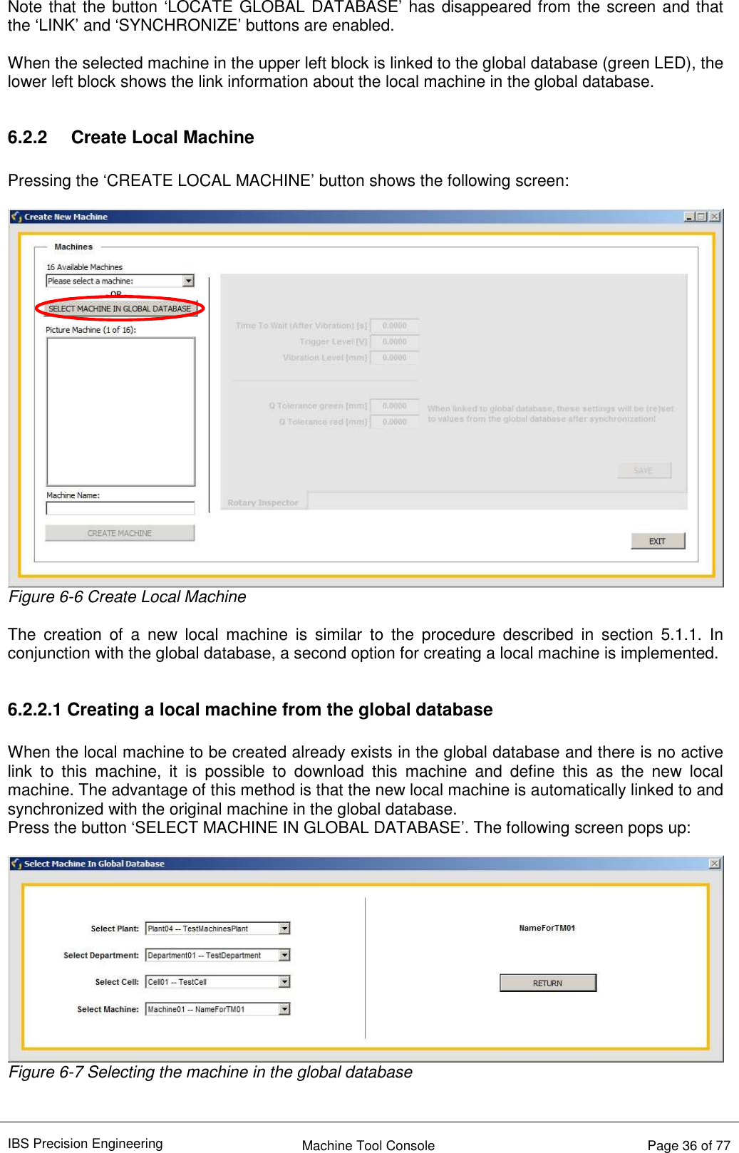
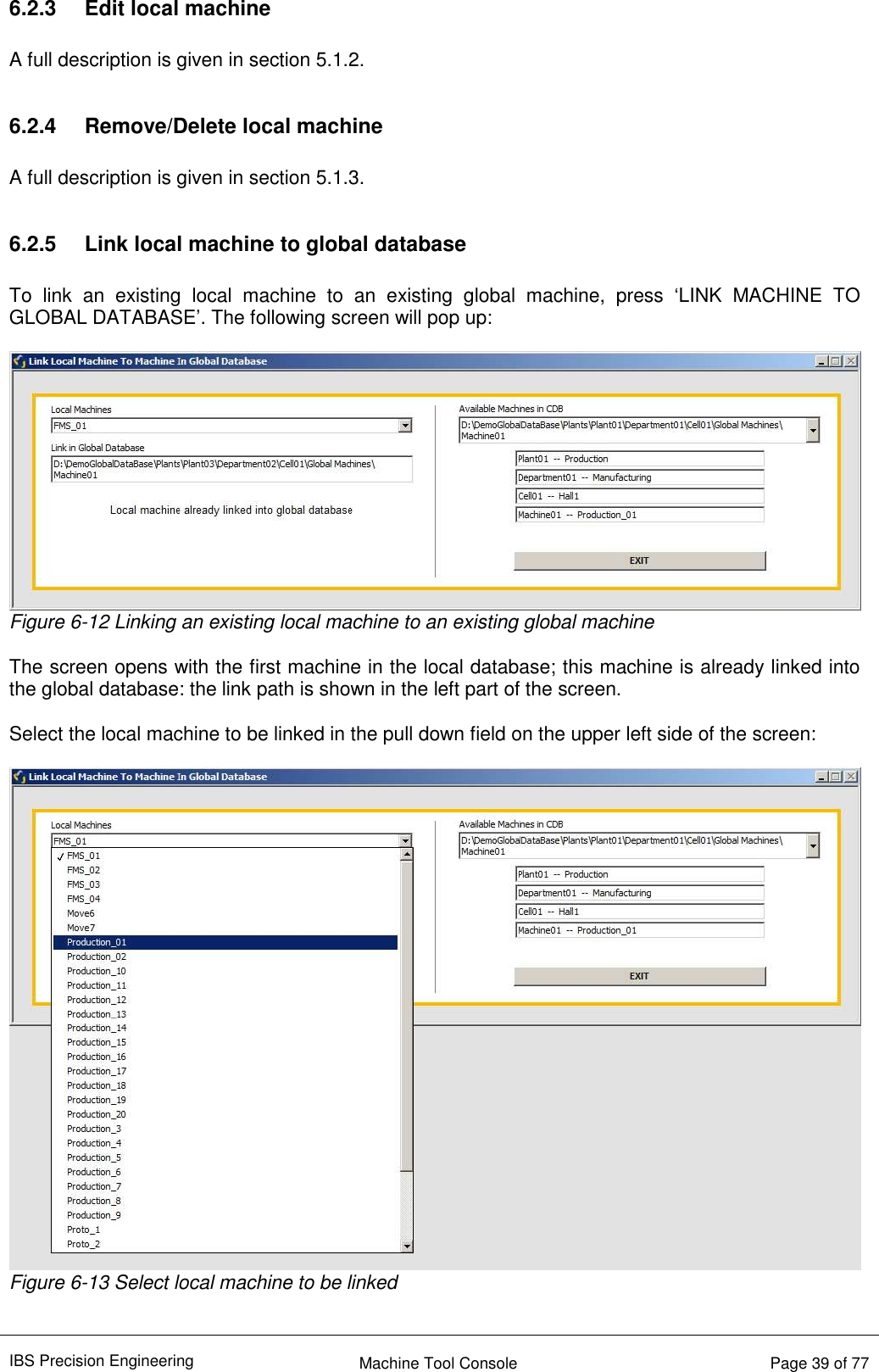
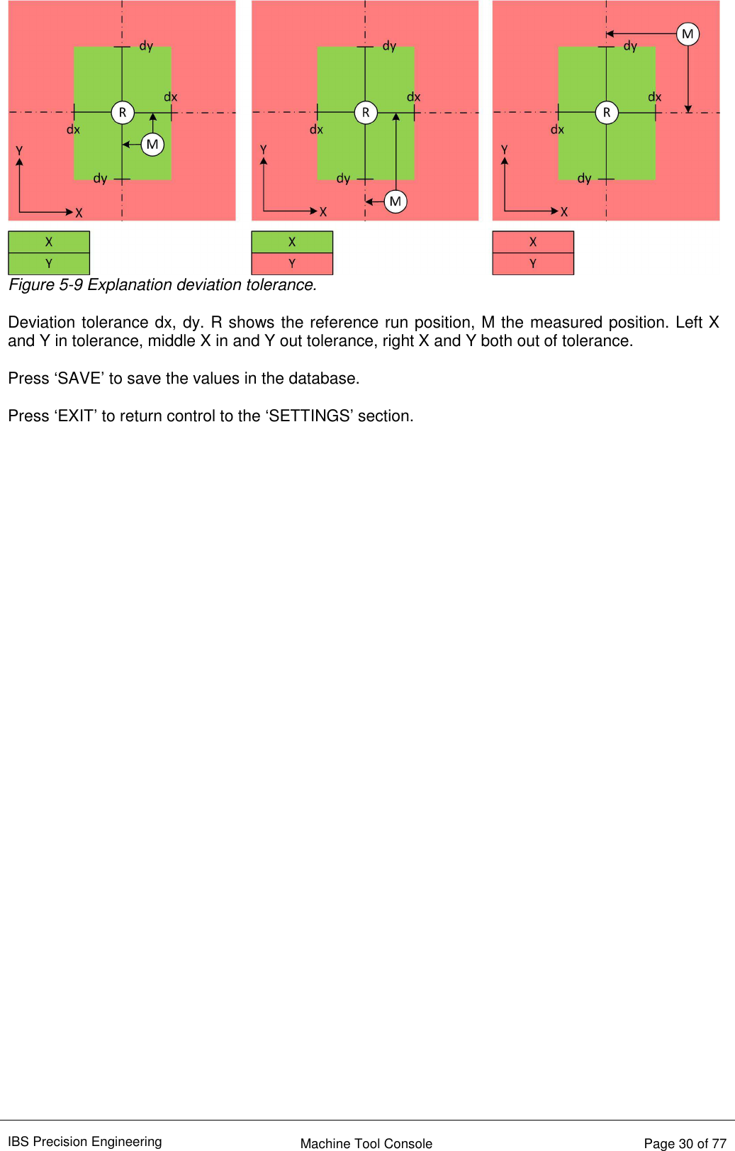
![IBS Precision Engineering Machine Tool Console Page 44 of 77 A.2 ConsoleConfig.ini file The ‘ConsoleConfig.ini’ file which contains the data which is exchanged between the Console and the selected application is as follows: [GENERAL INFO] DB_Location = "/C/Program Files (x86)/IBS Precision Engineering/MachineToolDataBase" SelectedProbe = "Probe_34" SelectedMachine = "LU-620" SelectedMeasurement = "PI_03_Balls" SelectedArtefact = "BB_UMTK_1619_june2010" NW_Adapter = "NETGEAR WNDA3100v2 N600 Wireless Dual Band USB Adapter" NW_Adapter_GUID = "2614341687_41530_19167_163_200_237_7_27_208_76_79" NW_Profile = "TRINITY_001_0034" Xbee_Vs_S6B = 0 Probe_Available = 1 Where: 1. DB_Location is the location of the database directory structure; 2. SelectedProbe is the current wireless ‘Trinity’ measuring head and refers to the directory name which is, in turn, part of the ‘probes’ directory. In this ‘Probe_xx’ directory a configuration file is read which contains all network settings for this particular probe; 3. SelectedMachine is the current machine on which measurements will be performed; 4. SelectedMeasurement is the current measurement which will be performed; 5. SelectedArtefact is only used by the ‘Position Analyzer’ and will further be ignored; 6. NW_Adapter is the description of the type name of the used network adapter, this is NOT a user given name; 7. NW_Adapter_GUID is the ID number of the network adapter which is set in the hardware, windows uses this number for network adapter identification. The Console software needs this number in order to be able to call the adapter for signal strength information; 8. NW_Profile is the current network profile the Console software uses to set and load the network profile in windows; 9. Xbee_Vs_S6B is the version number of the wireless interface inside the wireless probe. Currently, there are two different types of wireless interfaces for the probe: version ‘S6’ and the newer version ‘S6B’. The Console software has to determine which version is contained in the current probe because the command set used to control this interface is different in both versions; 10. When the wireless probe is available and recognized in the system this value is set to ‘1’ and the applications can work with the wireless probe to perform measurements. Otherwise, when the probe is not available and/or recognized in the system, the applications can still be called and used for analytical purposes if available. Obviously, measurements cannot be performed in this mode and this value is set to ‘0’. This information is initially read by the Console at startup and shown on the screen as the previous setting. When all desired selections are made and the application (e.g. Position Inspector) is started, this data is written to this file BEFORE the application starts. The application reads this data at startup and the appropriate settings for machine, measurement and probe are retrieved from the various locations in the database to make an instant correct measurement possible.](https://usermanual.wiki/IBS-Precision-Engineering/TRINITY/User-Guide-3128935-Page-44.png)