ICOM orporated 236702 VHF FM Repeater, Model ICFR3000 User Manual IC FR3000 FR4000
ICOM Incorporated VHF FM Repeater, Model ICFR3000 IC FR3000 FR4000
UserManual.wiki
>
ICOM orporated
>
236702 User Manual
Manual
Navigation menu
Upload a User Manual
Namespaces
Wiki Guide
HTML
PDF
Info
Views
User Manual
Discussion / Help
Navigation
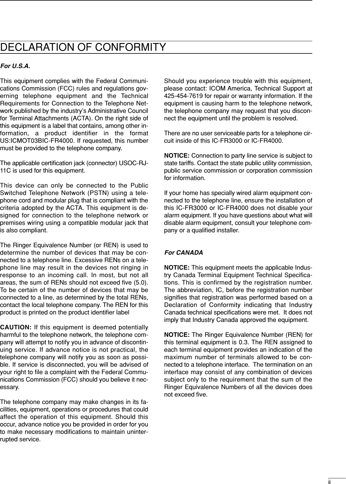
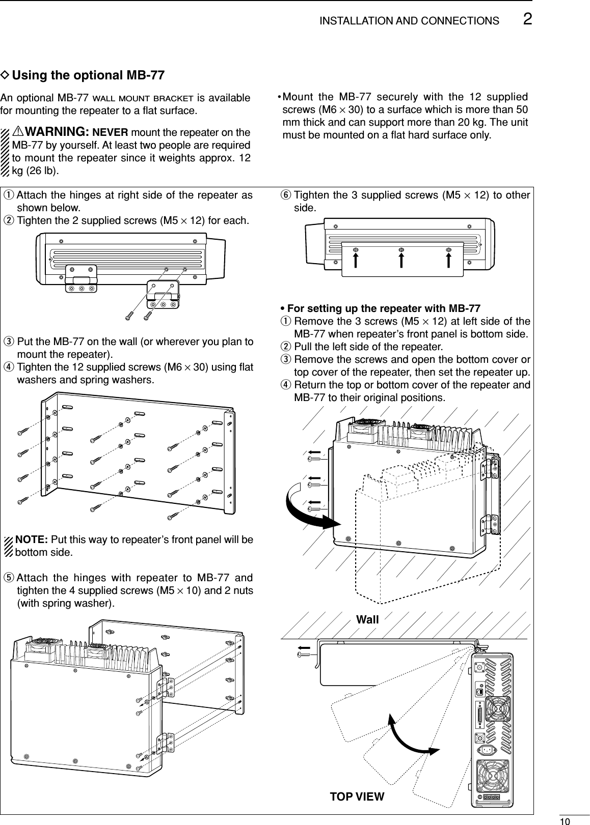
![iIMPORTANTREAD THIS INSTRUCTION MANUALCAREFULLY before attempting to operate the re-peater.SAVE THIS INSTRUCTION MANUAL– Thismanual contains important safety and operating in-structions for the IC-FR3000/FR4000 series.EXPLICIT DEFINITIONSRWARNING HIGH VOLTAGE! NEVER at-tach an antenna or internal antenna connector duringtransmission. This may result in an electrical shock orburn.RWARNING HIGH VOLTAGE! NEVER installthe antenna at any place that person touch the an-tenna easily during transmission. This may result in anelectrical shock or burn.RNEVER apply AC to the [BATTERY] terminals onthe repeater rear panel. This could cause a fire ordamage the repeater.RNEVER apply more than 16 V DC, such as a 24 Vbattery, to the [BATTERY] terminals on the repeaterrear panel. This could cause a fire or damage the re-peater.RNEVER let metal, wire or other objects touch anyinternal part or connectors on the rear panel of the re-peater. This may result in an electric shock.RNEVER expose the repeater to rain, snow or anyliquids.AVOID using or placing the repeater in areas with tem-peratures below –30°C (–22°F) or above +60°C(+140°F). Be aware that temperatures on a vehicle’sdashboard can exceed 80°C (+176°F), resulting in per-manent damage to the repeater if left there for ex-tended periods.AVOID placing the repeater in excessively dusty envi-ronments or in direct sunlight.AVOID putting anything on top of the repeater. This willobstruct heat dissipation.Place the repeater in a secure place to avoid inadver-tent use by children.BE CAREFUL! The heatsink will become hot when op-erating the repeater continuously for long periods.BE CAREFUL! If a linear amplifier is connected, setthe repeater’s RF output power to less than the linearamplifier’s maximum input level, otherwise, the linearamplifier will be damaged.Use Icom microphones only (optional). Other manu-facturer’s microphones have different pin assignments,and connection to the IC-FR3000/FR4000 series maydamage the repeater.For U.S.A. onlyCAUTION: Changes or modifications to this repeater,not expressly approved by Icom Inc., could void yourauthority to operate this repeater under FCC regula-tions.CAUTION: This repeater is intended for use as a fixedbase station with the antenna located outdoors on therooftop or on antenna tower.PRECAUTIONWORDR WARNINGCAUTIONNOTEDEFINITIONPersonal injury, fire hazard or electric shock may occur.Equipment damage may occur.If disregarded, inconvenience only. No risk of personal injury, fire or electric shock.Icom, Icom Inc. and the logo are registered trademarksof Icom Incorporated (Japan) in the United states, the UnitedKingdom, Germany, France, Spain, Russia and/or other coun-tries.](https://usermanual.wiki/ICOM-orporated/236702/User-Guide-333460-Page-2.png)
![iiiFORWARDThank you for purchasing this Icom product. The IC-FR3000/FR4000 VHF/UHF FM REPEATERis designedand built with Icom’s state of the art technology andcraftsmanship. With proper care, this product shouldprovide you years of trouble-free operation.We want to take a couple of moments of your time tothank you for making the IC-FR3000/FR4000 your re-peater of choice, and hope you agree with Icom’s phi-losophy of “technology first.” Many hours of researchand development went into the design of your IC-FR3000/FR4000 series.DFEATURES❍50 W continuous full duty cycle operationThis repeater looks as good as it performs. A ruggedheatsink, large cooling fans and a high performancepower module provide the repeater with a stable50 W at full duty cycle operation.❍Automatic battery backup systemA built-in backup system supports automatic switch-ing to an external power supply (13.6 V DC) if theAC power supply fails.❍Multiple CTCSS & DTCS tone memorieswith multiple memory channelsUp to 16 CTCSS/DTCS tones (TX/RX tones respec-tively) can be programmed in a channel. This fea-ture allows you to share a channel with multiple usergroups. You can also give priority/exclusive use to aspecified group simply by programming differenttones to another memory channel. Ideal for manydifferent applications.❍Built-in 2-Tone, 5-Tone, DTMF encoder &decoderMultiple signaling systems are equipped as stan-dard. These systems are fully compatible with IcomF-series radios.❍Telephone interconnect capability❍DTMF remote control capabilityYou can control the repeater from a remote locationover the air or over a phone line with DTMF.❍Other features- PC programmable- Wall or 19 inch rack mount (optional MB-77/MB-78)- Optional Voice Scrambler Unit (UT-109 #01/UT-110#01) for base operating modeSUPPLIED ACCESSORIESThe following accessories are supplied with IC-FR3000/FR4000 series[AC120V version]qAC power cable (OPC-510) ……………………… 1wSpare fuses (FGB 1 A) …………………………… 1eSpare fuses (ATC 20)……………………………… 2[AC220V version]qAC power cable (OPC-492) ……………………… 1wSpare fuses (FGB 1 A) …………………………… 1eSpare fuses (ATC 20)……………………………… 2qweqwe](https://usermanual.wiki/ICOM-orporated/236702/User-Guide-333460-Page-4.png)
![1PANEL DESCRIPTION1■Front panelqPOWER SWITCH [POWER]Toggles to turn the repeater power ON or OFF.wMICROPHONE/SPEAKER CONNECTOR [MIC/SP]This 8-pin modular jack accepts the optional micro-phone.q+9 V DC output (Max. 10 mA)wI/O port for PC programmingeNCrM PTT (Input port for TX control)tMicrophone groundyMicrophone inputuGroundiM MONI (Input port for monitor control)eLINE CONNECTOR [LINE]This 4-pin modular jack accepts to connect to 2 wiresystem telephone cable.• See p. 7 for line connector information.rVOLUME CONTROL [VOLUME] (p. 12)Adjusts the audio output level.tSQUELCH CONTROL [SQUELCH]➥While in base operating mode, adjusts thesquelch threshold level. (p. 12)➥While in repeater operating mode, this knob is notactivate.yCHANNEL SELECT SWITCHES [DN/UP]Push either switch to select the operating channel.uMONITOR SWITCH [MONI]➥Push to monitor the operating frequency.iMODE SELECT SWITCH [RPT/BASE]Toggles the repeater or base operating mode whenpushed.• When setting up a repeater system using IC-FR3000/FR4000 only, select a repeater operating mode.• When using IC-FR3000/FR4000 as full (or half) duplextransceiver or setting up a repeater system connectingan external controller, select a base operating mode.oREMOTE CONTROL SWITCH [REMOTE]Toggles to activate or inactivate the remote controloperation when pushed.!0 AF MUTE CONTROL [SP MUTE]Mutes the audio output.!1 INTERNAL SPEAKERMonitors received signals.!2 BASE OPERATING MODE INDICATORLights green while in base operating mode.!3 REMOTE CONTROL MODE INDICATORLights green while in remote control operation.!4 TRANSMIT INDICATORLights red while transmitting.!5 BUSY INDICATORLights green while receiving a signal or when thenoise squelch is open.qiqwe t y u i o !0!2 !1!3!4!5!6!7!8!9rFunction display (p. 2)](https://usermanual.wiki/ICOM-orporated/236702/User-Guide-333460-Page-6.png)
![21PANEL DESCRIPTION!6 ANI CLEAR SWITCH [ANI CLR]Push for 1 sec. to clear the received ANI ID indica-tion on the display and returns to original indication.NOTE: This switch is no function available for someversions.!7 DEALER-PROGRAMMABLE SWITCH [PROG]Toggles the pre-programmed function ON or OFFwhen pushed.!8 PROGRAMMED FUNCTION INDICATORLights green while pre-programmed function is acti-vated.!9 DC INDICATORLights green when in DC operation.DDFunction displayqMEMORY CHANNEL INDICATORShows the selected memory channel.wTRANSMIT POWER INDICATOR Shows the output power level.eAUDIBLE INDICATOR “@” appears in an audible condition, disappears inan inaudible condition. (When an audible condition,audio mute is cancelled.)rALPHANUMERIC INDICATORSShows the variety text or code information.32HH@HICOMHINC.qwer■Rear panelqTRANSMIT ANTENNA CONNECTOR [TX/TX•RX]➥Connects a transmit antenna (impedance: 50 Ω)and outputs transmit signals.➥When installing an optional internal duplexer(supplied by third party), this connects the trans-mit receive to an antenna. wEXTERNAL SPEAKER CONNECTOR [EXT SP]Accepts a 4 Ωexternal speaker.eREMOTE CONNECTOR [REMOTE]Connects to the remote controller.• See p. 3 for remote connector information.rACCESSORY CONNECTOR [ACC]Connects to the remote controller.• See pgs. 3, 4 for accessory connector information.tRECEIVE ANTENNA CONNECTOR [RX]➥Connects a receive antenna (impedance: 50 Ω)and inputs receiving signals.➥When installing an internal duplexer (supplied bythird party), do not use this connector.yAC POWER SOCKET [AC]Connects the supplied AC power cable to a domes-tic AC outlet.uGROUND TERMINAL [GND]Ground the repeater through this terminal to preventelectric shocks, TVI, BCI and other problems.iDC POWER INPUT TERMINALS [BATTERY]Connects the 12 V storage battery for the repeaterbackup when the AC power is interrupted. Theseterminals are also used for DC power operation.CAUTION: NEVER short the (+) line of the DCpower cable to repeater’s chassis, when connectingDC power cable to the [BATTERY] terminals. Oth-erwise, there is danger of electric shock and/orequipment damage.TX/TX•RXEXT SP REMOTEACC RXGNDACBATTERYq e r t y uiw](https://usermanual.wiki/ICOM-orporated/236702/User-Guide-333460-Page-7.png)
![31PANEL DESCRIPTIONDRemote connectorPin No. Pin Name Description Specification12345678–PTT+PTT–AFOUT+AFOUT–EXTMOD+EXTMOD–BUSY+BUSYInput terminals to transmit the repeater in rela-tion to the external equipment. An opto-isolatoris provided to facilitate PTT signals.Output terminal for AF signals from the AF de-tector circuit via the bandpass filter. Output levelis fixed, regardless of [AF] control.Input terminal for the modulation circuit.Output terminal for squelch condition(Open/Close). An opto-isolator is provided to fa-cilitate BUSY signals.High voltage=PTT ON (transmits)Hi-Z=PTT OFFOutput impedance: 600 ΩInput impedance: 600 ΩOpen collector=BUSY OFF0 V=BUSY ON (Squelch is opened)qiDAccessory connectorPin No. Pin Name Description Specification1234567891011121314BUSY OUTCOAXIAL SWM/S IND1D3EXT RPT/BASEEXT MONIEXT DTCSEXTMOD IN BEXTMOD IN AAF OUTDISC OUT+15VTX OUTOutput terminal for busy signal.Output terminal for coaxial switching (antenna switching)signal.Input terminal for master/slave signal.Input terminal for selecting memory channel.Input terminal for selecting memory channel.Input terminal for repeater/base operating mode switchingsignal.Input terminal for monitor function.Input terminal for continuous tone (CTCSS/DTCS) signal.Input terminal for the modulation signals applied to input ofthe splutter filter circuit.Input terminal for the modulation signal applied to input ofthe pre-emphasis circuit via the bandpass filter.Output terminal for AF signals from the AF detector circuitvia the bandpass filter. Output level is fixed, regardless of[AF] control.Output terminal for AF signals from the AF detector circuit.Output level is fixed, regardless of [AF] control.Output terminal for +15V DC while in AC operation. (While inDC operation, same as input DC.)Output terminal for transmission state.Open collector=OFF, 0 V=ONOpen collector=OFF0 V=ON+5 V pull up, Active=L+5 V pull up, Active=L+5 V pull up, Active=L+5 V pull upActive=L+5 V pull up, Active=LInput impedance: 100 kΩ(approx.)Input impedance: 600 Ω(approx.)Input impedance: 600 Ω(approx.)Output impedance: 1 kΩ(approx.)Output impedance: 1 kΩ(approx.)Output current: Less than 1 AOpen collector=OFF, 0 V=ONq!3!4@5](https://usermanual.wiki/ICOM-orporated/236702/User-Guide-333460-Page-8.png)
![41PANEL DESCRIPTIONChannel D4 D3 D2 D1 D0(pin 18) (pin 5) (pin 17) (pin 4) (pin16)1 000002 000013 000104 000115 001006 001017 001108 001119 0100010 0 1 0 0 111 0 1 0 1 012 0 1 0 1 113 0 1 1 0 014 0 1 1 0 115 0 1 1 1 016 0 1 1 1 1Channel D4 D3 D2 D1 D0(pin 18) (pin 5) (pin 17) (pin 4) (pin16)17 1 0 0 0 018 1 0 0 0 119 1 0 0 1 020 1 0 0 1 121 1 0 1 0 022 1 0 1 0 123 1 0 1 1 024 1 0 1 1 125 1 1 0 0 026 1 1 0 0 127 1 1 0 1 028 1 1 0 1 129 1 1 1 0 030 1 1 1 0 131 1 1 1 1 032 1 1 1 1 1Accessory connector (continued)Pin No. Pin Name Description Specification15161718192021–2425M/S OUTD0D2D4EXT PTTRSSIAGNDDC GNDOutput terminal for master/slave signal.Input terminal for selecting memory channel.Input terminal for selecting memory channel.Input terminal for selecting memory channel.Input terminal for PTT signal.Output terminal for RSSI (Received Signal Strength Indica-tor) signal.Analog groundGround for +15 V DCOpen collector=OFF, 0V=ON+5 V pull up, Active=L+5 V pull up, Active=L+5 V pull up, Active=L+5 V pull up, Active=LOutput impedance: 1 kΩ(approx.)• Pin 4, pin 5, pins 16–18 select one of the 32 pre-programmed memory channels. (see table below)[0]: Hi-Z, [1]: 0 V (D0–D4: +5 V pull up)](https://usermanual.wiki/ICOM-orporated/236702/User-Guide-333460-Page-9.png)
![25INSTALLATION AND CONNECTIONS■UnpackingAfter unpacking, immediately report any damage to thedelivering carrier or dealer. Keep the shipping cartons.For a description and a diagram of accessory equip-ment included with the IC-FR3000/FR4000 series, see‘Supplied accessories’ on p. iii of this manual.■Selecting a locationSelect a location for the repeater that allows adequateair circulation, free from extreme heat, cold, or vibra-tions, and away from TV sets, TV antenna elements,radios and other electromagnetic sources.■Antenna connectionFor radio communications, the antenna is of critical im-portance, along with output power and sensitivity. Se-lect antenna(s), such as a well-matched 50 Ωantenna,and feedline. 1.5:1 or better of Voltage Standing WaveRatio (VSWR) is recommended for desired band. Ofcourse, the transmission line should be a coaxialcable.CAUTION: Protect repeater from lightning by usinga lightning arrestor.NOTE: There are many publications coveringproper antennas and their installation. Check withyour local dealer for more information and recom-mendations.■DuplexerA duplexer is separately required when only one an-tenna is used for both transmitting and receiving. Se-lect a duplexer according to the transmitting and re-ceiving frequencies. Ask your Dealer for details.■GroundingTo prevent electrical shock, television interference(TVI), broadcast interference (BCI) and other prob-lems, ground the transceiver through the [GND] termi-nal on the rear panel.For best results, connect a heavy gauge wire or strapto a long earth-sunk copper rod. Make the distance be-tween the [GND] terminal and ground as short as pos-sible.RRWARNING: NEVER connect the [GND] termi-nal to a gas or electric pipe, since the connectioncould cause an explosion or electric shock.TX/TX•RXEXT SP REMOTEACC RXGNDACBATTERYTYPE-N CONNECTOR INSTALLATION EXAMPLE30 mm ≈9⁄8in 10 mm ≈3⁄8in 1–2 mm ≈1⁄16 inSlide the nut, flat washer, rubber gasket and clamp over the coaxial cable, then cut the end of the cable evenly.Strip the cable and fold the braid back over the clamp.Soft solder the center conductor. Install the center conductor pin and solder it.Carefully slide the plug body into place aligning the center conductor pin on the cable. Tighten the nut onto the plug body.qwer15 mm3 mm 6 mmNo spaceSolder holeBe sure the center conductor is the same height as the plug body.Clamp CenterconductorWasherNut Rubber gasket](https://usermanual.wiki/ICOM-orporated/236702/User-Guide-333460-Page-10.png)
![62INSTALLATION AND CONNECTIONSTX/TX•RXEXT SP REMOTEACC RXGNDACBATTERY[TX(TX•RX) ANT] (p. 5) [RX ANT] (p. 5)TX•RX antenna required for installing an internal duplexer.GROUND (p. 5)[DC POWER INPUT TERMINAL] (p. 8)12 Vbattery SuppliedDC power cable+ red_ black CrimpSolderSM-25 DESKTOP MICROPHONE (optional)MICROPHONE CONNECTOR (Front panel view)HM-100N/TN HAND MICROPHONE(optional) q +9 V DC output (Max. 10 mA)w I/O port for PC programminge NCr M PTT (Input port for TX control)t Microphone groundy Microphone inputu Groundi M MONI (Input port for monitor control)qiCAUTION: DO NOT short pin 1 to ground as this can damage the internal 9 V regulator. DC voltage is applied to pin 1 for microphone operation. Take care when using a non-Icom microphone.Make sure the back up battery is correctly connected. Use a cable with following current capacity. Solder or clamp the cable lug when connecting the power cable to the backup battery to prevent voltage drops.Power cable current capacity: 25 A or more■Required connections](https://usermanual.wiki/ICOM-orporated/236702/User-Guide-333460-Page-11.png)
![72INSTALLATION AND CONNECTIONSTX/TX•RXEXT SP REMOTEACC RXGNDACBATTERYEXTERNAL SPEAKERsp-7icomUse a 4 Ω speaker.[REMOTE] (p. 3) ACC CONNECTOR (pgs. 3, 4)Used for external equipment control.Used for external equipment control.LINE CONNECTOR (Front panel view)q NC (No connection)w L1 input/outpute L2 input/outputr NC (No connection)qrTEL* This illustration is example only.Telephone connector type is different for some countries.■Advanced connections](https://usermanual.wiki/ICOM-orporated/236702/User-Guide-333460-Page-12.png)
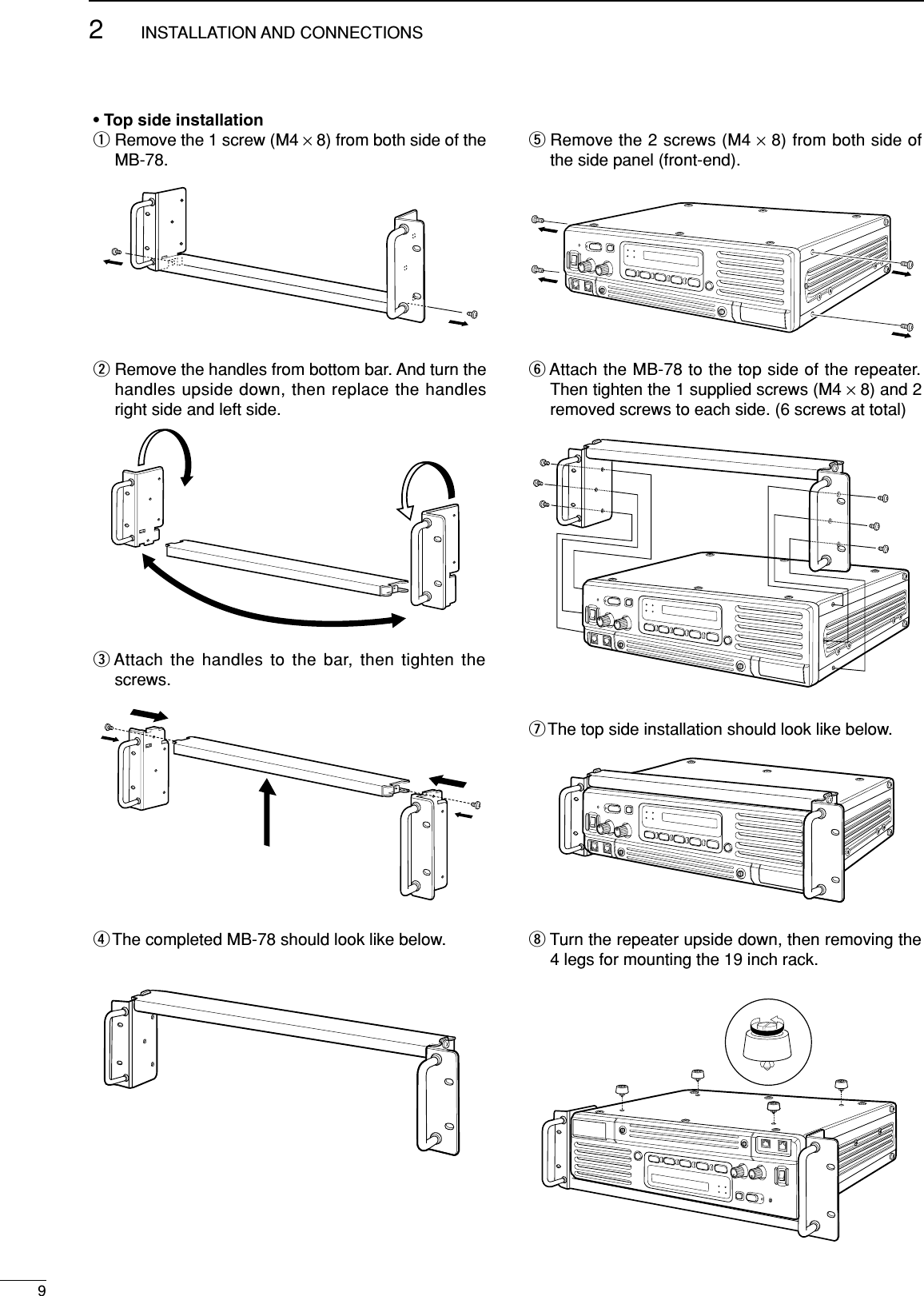
![82INSTALLATION AND CONNECTIONS■PowerMake sure the [POWER] switch is turned OFF whenconnecting an AC power cable and a backup battery(emergency power supply).The IC-FR3000/FR4000 series can operate with an ACor DC power supply. If AC power is interrupted whenoperating the repeater with an AC power supply, poweris automatically provided to the [BATTERY] terminals.NOTE: When repeat to turn the repeater ON andOFF quickly, the repeater may not turn ON. In thiscase turn OFF the power switch and wait for awhile, then turning power ON again.DIn AC operation• The [DC] indicator turns OFF.• Use the supplied AC power cable for connection to adomestic AC outlet.• Extension cords should not be used unless ab-solutely necessary. Using improper extension cordscould result in fire risk.• Usually the battery is continuously charged with asmall amount of current from an AC power supplythrough the regulator circuit in the repeater. Dis-charging is therefore prevented even if the battery isnot used for a long time.DIn DC operationCAUTION: Voltages greater than 16 V DC will dam-age the repeater. Check the source voltage beforeconnecting the power cable.• The [DC] indicator lights up green.• DO NOT place the backup battery on or near the re-peater. Lead-acid batteries should be placed at least5 m (16.4 ft.) away from the repeater. Use a heavyduty cable to make the connection and be sure boththe positive (red) and negative (black) terminals arecorrectly connected.• When connecting to the battery, keep in order to con-nect the DC power cable to the repeater first, thenthe positive (red) terminal and negative (black) termi-nal to the battery to prevent an electric shock.• After the battery is connected and the [POWER]switch is ON, the repeater continuously supplies ap-prox. 1 A for charging the battery. If the repeaterstops functioning while connected to the battery, dis-connect the battery, recharge it, then connect the bat-tery to continue operation after the battery is charged.During repeater transmission, approx. 17 A of batterypower is consumed.■Mounting the repeaterDUsing the optional MB-78An optional MB-78 19 INCH RACK MOUNT BRACKETisavailable for mounting the repeater into a 19 inch rack.The MB-78 can install the repeater’s bottom side andtop side.• Bottom side installationqRemove the 2 screws (M4 ×8) from both side of theside panel (front-end).wAttach the MB-78 to the bottom side of the repeater.eTighten the 1 supplied screws (M4 ×8) and 2 re-moved screws to each side. (6 screws at total)rThe completed bottom side installation should looklike below.](https://usermanual.wiki/ICOM-orporated/236702/User-Guide-333460-Page-13.png)
![412OPERATION■Turning power ONqPush [POWER] to turn power ON.wIf the repeater is programmed for a power on pass-word by an Icom Dealer, input digit codes directly.• The keys in the table below can be used for passwordinput.• The repeater detects numbers in the same block asidentical. Therefore “01234” and “56789” are the same.eWhen the “PASSWORD” indication does not clearafter inputting 4 digits, the input code number maybe incorrect. Turn power off and start over in thiscase.■Receiving and transmittingDReceivingqPush [POWER] to turn power ON.wSet the audio and squelch levels.➥Rotate [SQUELCH] fully counterclockwise in ad-vance.➥Rotate [VOLUME] to adjust the audio output level.➥Rotate [SQUELCH] clockwise until the noise dis-appears.ePush [UP] or [DN] to select the desired channel.•When receiving a signal, BUSY indicator turns ON andaudio is emitted from the speaker.•Further adjustment of [VOLUME] to a comfortable listen-ing level may be necessary at this point.DTransmittingqTake the microphone off hook.wWait for the channel to become clear.ePush and hold [PTT] to transmit, then speak into themicrophone at your normal voice level.rRelease [PTT] to receive.IMPORTANT:To maximize the readability of the transmitted signal: (1) Pause briefly after pushing [PTT].(2) Hold the microphone 1 to 2 inch (2.5 to 5 cm) fromyour mouth, then speak into the microphone at anormal voice level.KEY[DN] [UP] [MONI][RPT/BASE][REMOTE]NUMBER 012 3 4567 8 9](https://usermanual.wiki/ICOM-orporated/236702/User-Guide-333460-Page-17.png)
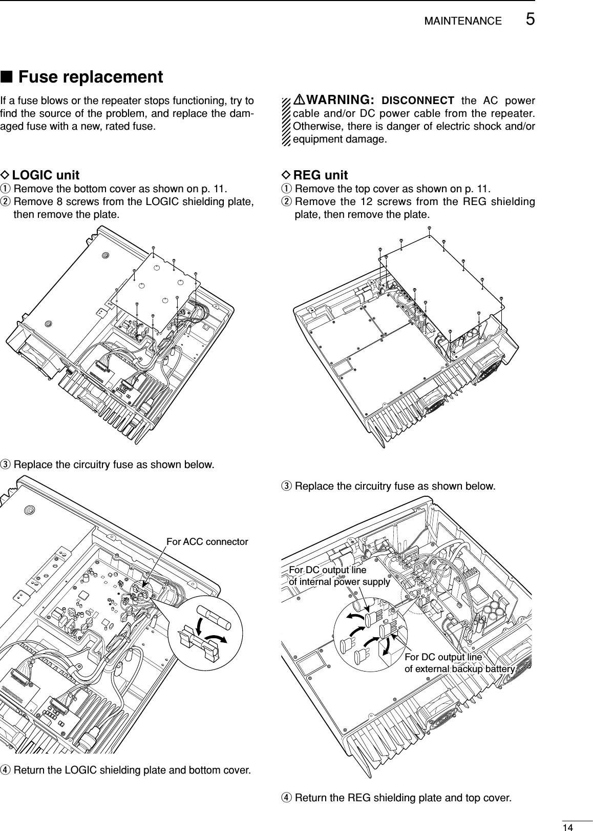
![513MAINTENANCEPROBLEM POSSIBLE CAUSE SOLUTION REF.■TroubleshootingThe following chart is designed to help correct prob-lems which are not equipment malfunctions.If you are unable to locate the cause of a problem orsolve it through the use of this chart, contact the near-est Icom Dealer or Service Center.Power does not come onwhen [POWER] switch isON.No sounds from thespeaker.Sensitivity is low andonly strong signals areaudible.Received signal cannotbe understood.Output power is too low.No contact possible withanother station.<DC operation>• DC power cable is improperly connected.<AC/DC common>• Fuse is blown.• Volume level is too low.• The squelch is closed.• The audio mute function is activated.•A selective call or squelch function is acti-vated such as 2/5 tone call or tone squelch.• While in base operating mode, the repeateris in the transmitting condition.• Antenna feedline or the antenna connectorhas a poor contact or short-circuited.• Optional voice scrambler is turned OFF.• Scrambler code is not set correctly.• Output power is set to Low.• The other station is using tone squelch.• While in base operating mode, the repeateris set to duplex.• Re-connect the DC power cable correctly.• Check the cause, then replace the fuse witha spare one. (Fuses are installed in the inter-nal REG unit and LOGIC unit.)• Rotate [VOLUME] clockwise to obtain a suit-able listening level.•While in base operating mode, rotate[SQUELCH] to counterclockwise to open thesquelch.• Push [SP MUTE] to the audio mute functionOFF• Turn the appropriate function OFF.• Push [PTT] on the microphone to receive orcheck the PTT line of an external unit, if con-nected.•Check and re-connect (or replace if neces-sary), the antenna feedline or antenna con-nector.• Turn the optional voice scrambler ON.• Reset the scrambler code.•Push channel selector to select the highpower operating channel.• Turn the tone squelch function ON.•Set the repeater to simplex, when othertransceiver is set to simplex.p. 6p. 14p. 12p. 12p. 1––p. 5––p. 1––](https://usermanual.wiki/ICOM-orporated/236702/User-Guide-333460-Page-18.png)