ICOM orporated 236803 UHF FM Repeater, Model ICFR4000 User Manual Manual
ICOM Incorporated UHF FM Repeater, Model ICFR4000 Manual
Manual
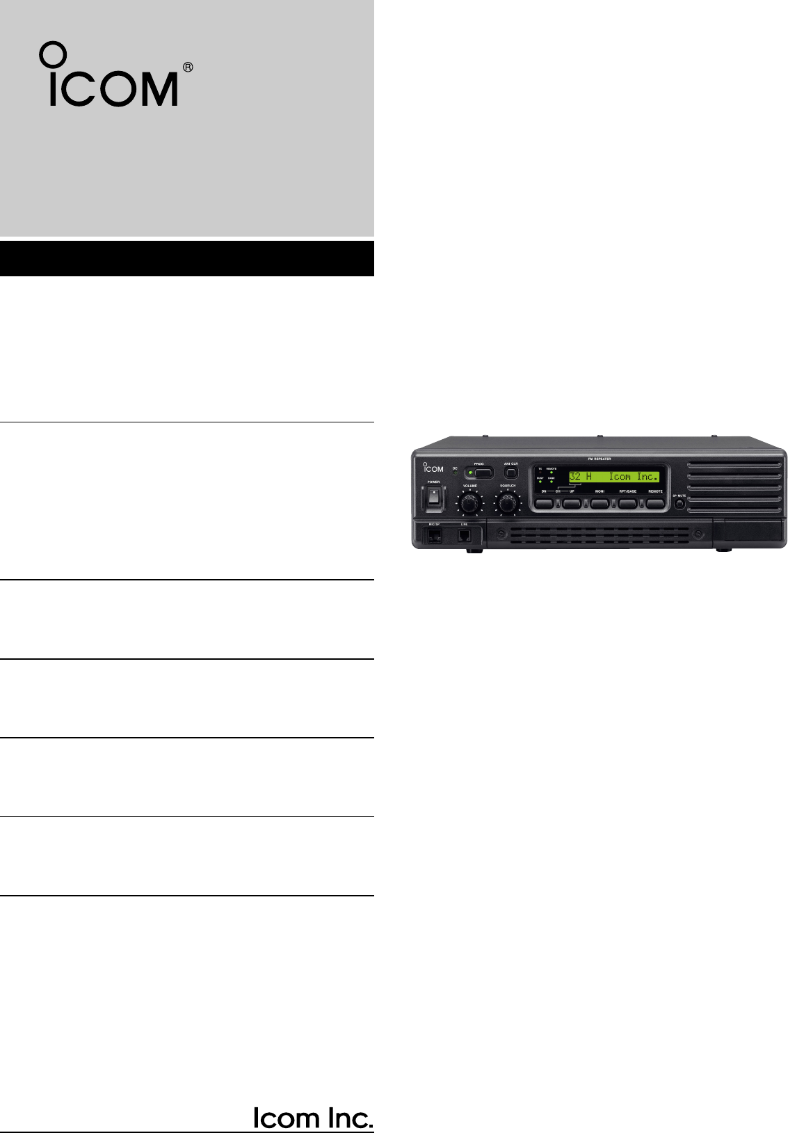
INSTRUCTION MANUAL
UHF FM REPEATER
iFR4000

i
IMPORTANT
READ THIS INSTRUCTION MANUAL
CAREFULLY before attempting to operate the re-
peater.
SAVE THIS INSTRUCTION MANUAL– This
manual contains important safety and operating in-
structions for the IC-FR4000.
EXPLICIT DEFINITIONS
RWARNING HIGH VOLTAGE! NEVER at-
tach an antenna or internal antenna connector during
transmission. This may result in an electrical shock or
burn.
RNEVER apply AC to the [BATTERY] terminals on
the repeater rear panel. This could cause a fire or
damage the repeater.
RNEVER apply more than 16 V DC, such as a 24 V
battery, to the [BATTERY] terminals on the repeater
rear panel. This could cause a fire or damage the re-
peater.
RNEVER let metal, wire or other objects touch any
internal part or connectors on the rear panel of the re-
peater. This may result in an electric shock.
RNEVER expose the repeater to rain, snow or any
liquids.
AVOID using or placing the repeater in areas with tem-
peratures below –30°C (–22°F) or above +60°C
(+140°F). Be aware that temperatures on a vehicle’s
dashboard can exceed 80°C (+176°F), resulting in per-
manent damage to the repeater if left there for ex-
tended periods.
AVOID placing the repeater in excessively dusty envi-
ronments or in direct sunlight.
AVOID putting anything on top of the repeater. This will
obstruct heat dissipation.
Place the repeater in a secure place to avoid inadver-
tent use by children.
BE CAREFUL! The heatsink will become hot when op-
erating the repeater continuously for long periods.
BE CAREFUL! If a linear amplifier is connected, set
the repeater’s RF output power to less than the linear
amplifier’s maximum input level, otherwise, the linear
amplifier will be damaged.
Use Icom microphones only (optional). Other manu-
facturer’s microphones have different pin assignments,
and connection to the IC-FR4000 may damage the re-
peater.
For U.S.A. only
CAUTION: Changes or modifications to this repeater,
not expressly approved by Icom Inc., could void your
authority to operate this repeater under FCC regula-
tions.
PRECAUTION
WORD
R
WARNING
CAUTION
NOTE
DEFINITION
Personal injury, fire hazard or electric
shock may occur.
If disregarded, inconvenience only.
No risk of personal injury, fire or
electric shock.
Equipment damage may occur.
Icom, Icom Inc. and the logo are registered trademarks
of Icom Incorporated (Japan) in the United states, the United
Kingdom, Germany, France, Spain, Russia and/or other coun-
tries.
ii
IMPORTANT ......................................................................... i
EXPLICIT DEFINITIONS ...................................................... i
PRECAUTION ....................................................................... i
FORWARD ........................................................................... ii
SUPPLIED ACCESSORIES ................................................ ii
TABLE OF CONTENTS ....................................................... ii
1 PANEL DESCRIPTION ................................... 1 –4
■Front panel ............................................................ 1
■Rear panel ............................................................ 2
2 INSTALLATION AND CONNECTIONS ........ 5 –10
■Unpacking ............................................................. 5
■Selecting a location ............................................... 5
■Antenna connection .............................................. 5
■Duplexer ................................................................ 5
■Grounding ............................................................. 5
■Required connections ........................................... 6
■Advanced connections .......................................... 7
■Power .................................................................... 8
■Mounting the repeater ........................................... 8
3 OPTIONAL UNIT INSTALLATION ..................... 11
■Opening the repeater’s case ............................... 11
■Voice scrambler unit installation .......................... 11
4 OPERATION ...................................................... 12
■Turning power ON ............................................... 12
■Receiving and transmitting .................................. 12
■Set mode ............................................................. 12
5 MAINTENANCE ........................................... 13–14
■Troubleshooting .................................................. 13
■Fuse replacement ............................................... 14
6 SPECIFICATIONS AND OPTIONS ................... 15
TABLE OF CONTENTS
FORWARD
Thank you for purchasing this Icom product. The IC-
FR4000
UHF FM REPEATER
is designed and built with
Icom’s state of the art technology and craftsmanship.
With proper care, this product should provide you
years of trouble-free operation.
We want to take a couple of moments of your time to
thank you for making the IC-FR4000 your repeater of
choice, and hope you agree with Icom’s philosophy of
“technology first.” Many hours of research and devel-
opment went into the design of your IC-FR4000 series.
D
FEATURES
❍Highly efficient and stable output power
Icom’s expertise in radio technology has produced
the IC-FR4000, an FM repeater highly efficient and
completely stable with a PA module used in the
transmitter output circuit.
❍
2-way power supply system
The repeater has two-way, AC and DC power source
capability. If AC power to the repeater is interrupted,
DC power can be automatically connected as a
backup power source.
❍Heavy duty power supply
A heavy duty power supply unit is adopted to follow
load fluctuations and secure continuous 24-hour op-
eration.
❍Other features
- PC programmable
- Wall or rack mount (optional MB-77/MB-78)
- Optional Voice Scrambler Unit (UT-109 #01/UT-110
#01) for base operating mode
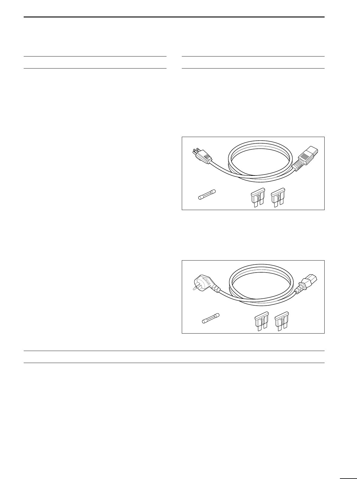
SUPPLIED ACCESSORIES
The following accessories are supplied with IC-
FR4000 series
[AC120V version]
qAC power cable (OPC-510) ……………………… 1
wSpare fuses (FGB 1 A) …………………………… 1
eSpare fuses (ATC 20)……………………………… 2
[AC220V version]
qAC power cable (OPC-492) ……………………… 1
wSpare fuses (FGB 1 A) …………………………… 1
eSpare fuses (ATC 20)……………………………… 2
q
we
q
we
1PANEL DESCRIPTION
1
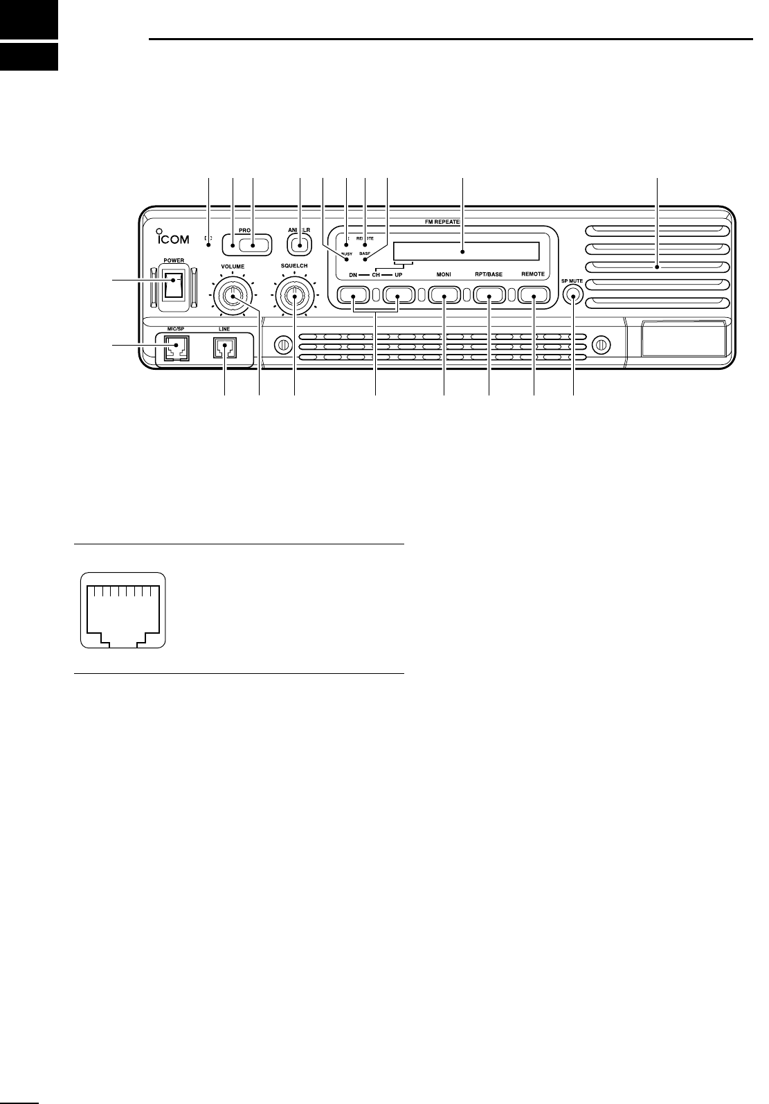
■Front panel
qPOWER SWITCH [POWER]
Toggles to turn the repeater power ON or OFF.
w
MICROPHONE/SPEAKER CONNECTOR [MIC/SP]
This 8-pin modular jack accepts the optional micro-
phone.
q+9 V DC output (Max. 10 mA)
wI/O port for PC programming
eSpeaker output
rM PTT (Input port for TX control)
tMicrophone ground
yMicrophone input
uSpeaker ground
iM MONI (Input port for monitor control)
eLINE CONNECTOR [LINE]
This 4-pin modular jack accepts to connect to 2 wire
system telephone cable.
• See p. 7 for line connector information.
rVOLUME CONTROL [VOLUME] (p. 12)
Adjusts the audio output level.
tSQUELCH CONTROL [SQUELCH]
➥While in base operating mode, adjusts the
squelch threshold level. (p. 12)
➥While in repeater operating mode, this knob is not
activate.
• Squelch level is set on the set mode. (p. 12)
yCHANNEL SELECT SWITCHES [DN/UP]
Push either switch to select the operating channel.
uMONITOR SWITCH [MONI]
➥Push to monitor the operating frequency.
iMODE SELECT SWITCH [RPT/BASE]
Toggles the repeater or base operating mode when
pushed.
• When setting up a repeater system using IC-FR4000
only, select a repeater operating mode.
• When using IC-FR4000 as full (or half) duplex trans-
ceiver or setting up a repeater system connecting an ex-
ternal controller, select a base operating mode.
oREMOTE CONTROL SWITCH [REMOTE]
Toggles to activate or inactivate the remote control
operation when pushed.
!0 AF MUTE CONTROL [SP MUTE]
Mutes the audio output.
!1 INTERNAL SPEAKER
Monitors received signals.
!2 BASE OPERATING MODE INDICATOR
Lights green while in base operating mode.
!3 REMOTE CONTROL MODE INDICATOR
Lights green while in remote control operation.
!4 TRANSMIT INDICATOR
Lights red while transmitting.
!5 BUSY INDICATOR
Lights green while receiving a signal or when the
noise squelch is open.
qi
q
w
e t y u i o !0
!2 !1!3!4!5!6!7
!8!9
r
Function display (p. 2)
2
1
PANEL DESCRIPTION
!6 ANI CLEAR SWITCH [ANI CLR]
➥Push momentarily to turn OFF the alert tone
when receiving a call with ANI code.
➥Push for 1 sec. to clear the received ANI ID indi-
cation on the display and returns to original indi-
cation.
NOTE: This switch is no function available for some
versions.
!7 DEALER-PROGRAMMABLE SWITCH [PROG]
Toggles the pre-programmed function ON or OFF
when pushed.
!8 PROGRAMMED FUNCTION INDICATOR
Lights green while pre-programmed function is acti-
vated.
!9 DC INDICATOR
Lights green when in DC operation.
DDFunction display
qMEMORY CHANNEL INDICATOR
Shows the selected memory channel.
wTRANSMIT POWER INDICATOR
Shows the output power level.
eAUDIBLE INDICATOR
“@” appears in an audible condition, disappears in
an inaudible condition. (When an audible condition,
audio mute is cancelled.)
rALPHANUMERIC INDICATORS
Shows the variety text or code information.
32HH@HICOMHINC.
qwer
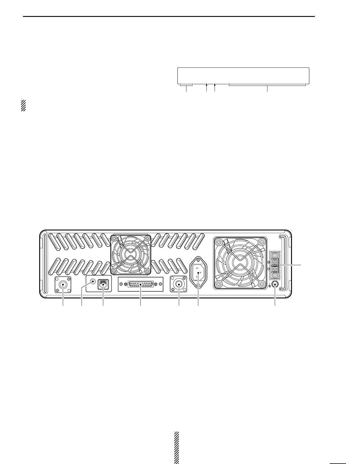
■Rear panel
qTRANSMIT ANTENNA CONNECTOR [TX/TX•RX]
➥Connects a transmit antenna (impedance: 50 Ω)
and outputs transmit signals.
➥When installing an optional internal duplexer
(supplied by third party), this connects the trans-
mit receive to an antenna.
w
EXTERNAL SPEAKER CONNECTOR [EXT SP]
Accepts a 4 Ωexternal speaker.
eREMOTE CONNECTOR [REMOTE]
Connects to the remote controller.
• See p. 3 for remote connector information.
rACCESSORY CONNECTOR [ACC]
Connects to the remote controller.
• See pgs. 3, 4 for accessory connector information.
tRECEIVE ANTENNA CONNECTOR [RX]
➥Connects a receive antenna (impedance: 50 Ω)
and inputs receiving signals.
➥When installing an internal duplexer (supplied by
third party), do not use this connector.
yAC POWER SOCKET [AC]
Connects the supplied AC power cable to a domes-
tic AC outlet.
uGROUND TERMINAL [GND]
Ground the repeater through this terminal to prevent
electric shocks, TVI, BCI and other problems.
iDC POWER INPUT TERMINALS [BATTERY]
Connects the 12 V storage battery for the repeater
backup when the AC power is interrupted. These
terminals are also used for DC power operation.
CAUTION: NEVER short the (+) line of the DC
power cable to repeater’s chassis, when connecting
DC power cable to the [BATTERY] terminals. Oth-
erwise, there is danger of electric shock and/or
equipment damage.
TX/TX•RX
EXT SP REMOTE
ACC RX
GND
AC
BATTERY
q e r t y u
i
w
3
1PANEL DESCRIPTION
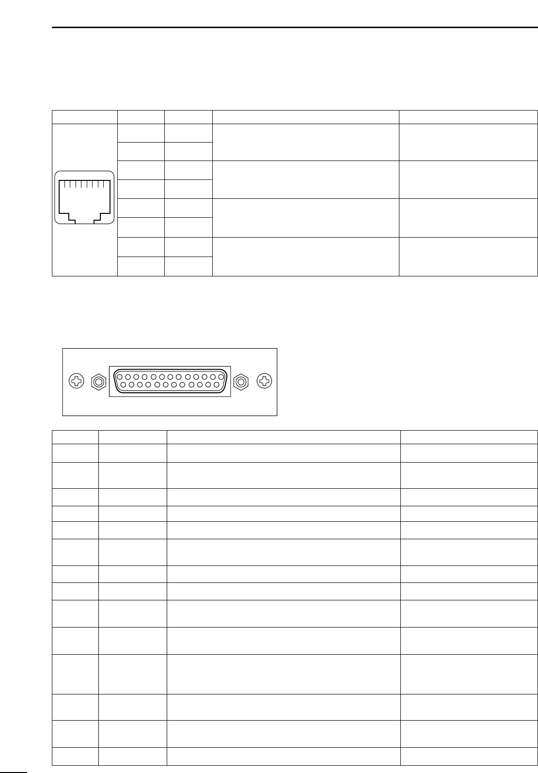
DREMOTE CONNECTOR
Pin No. Pin Name Description Specification
1
2
3
4
5
6
7
8
–PTT
+PTT
–AFOUT
+AFOUT
–EXTMOD
+EXTMOD
–BUSY
+BUSY
Input terminals to transmit the repeater in rela-
tion to the external equipment. An opto-isolator
is provided to facilitate PTT signals.
Output terminal for AF signals from the AF de-
tector circuit via the bandpass filter. Output level
is fixed, regardless of [AF] control.
Input terminal for the modulation circuit.
Output terminal for squelch condition
(Open/Close). An opto-isolator is provided to fa-
cilitate BUSY signals.
High voltage=PTT ON (transmits)
Hi-Z=PTT OFF
Output impedance: 600 Ω
Input impedance: 600 Ω
Open collector=BUSY OFF
0 V=BUSY ON (Squelch is opened)
qi
DACCESSORY CONNECTOR
Pin No. Pin Name Description Specification
1
2
3
4
5
6
7
8
9
10
11
12
13
14
BUSY OUT
COAXIAL SW
M/S IN
D1
D3
EXT RPT/BASE
EXT MONI
EXT DTCS
EXTMOD IN B
EXTMOD IN A
AF OUT
DISC OUT
+15V
TX OUT
Output terminal for busy signal.
Output terminal for coaxial switching (antenna switching)
signal.
Input terminal for master/slave signal.
Input terminal for selecting memory channel.
Input terminal for selecting memory channel.
Input terminal for repeater/base operating mode switching
signal.
Input terminal for monitor function.
Input terminal for continuous tone (CTCSS/DTCS) signal.
Input terminal for the modulation signals applied to input of
the splutter filter circuit.
Input terminal for the modulation signal applied to input of
the pre-emphasis circuit via the bandpass filter.
Output terminal for AF signals from the AF detector circuit
via the bandpass filter. Output level is fixed, regardless of
[AF] control.
Output terminal for AF signals from the AF detector circuit.
Output level is fixed, regardless of [AF] control.
Output terminal for +15V DC while in AC operation. (While in
DC operation, same as input DC.)
Output terminal for transmission state.
Open collector=OFF, 0 V=ON
Open collector=OFF
0 V=ON
+5 V pull up, Active=L
+5 V pull up, Active=L
+5 V pull up, Active=L
+5 V pull up
Active=L
+5 V pull up, Active=L
Input impedance: 100 kΩ(approx.)
Input impedance: 600 Ω(approx.)
Input impedance: 600 Ω(approx.)
Output impedance: 1 kΩ(approx.)
Output impedance: 1 kΩ(approx.)
Output current: Less than 1 A
Open collector=OFF, 0 V=ON
q!3
!4@5

4
1
PANEL DESCRIPTION
Channel D4 D3 D2 D1 D0
(pin 18) (pin 5) (pin 17) (pin 4) (pin16)
1 00000
2 00001
3 00010
4 00011
5 00100
6 00101
7 00110
8 00111
9 01000
10 0 1 0 0 1
11 0 1 0 1 0
12 0 1 0 1 1
13 0 1 1 0 0
14 0 1 1 0 1
15 0 1 1 1 0
16 0 1 1 1 1
Channel D4 D3 D2 D1 D0
(pin 18) (pin 5) (pin 17) (pin 4) (pin16)
17 1 0 0 0 0
18 1 0 0 0 1
19 1 0 0 1 0
20 1 0 0 1 1
21 1 0 1 0 0
22 1 0 1 0 1
23 1 0 1 1 0
24 1 0 1 1 1
25 1 1 0 0 0
26 1 1 0 0 1
27 1 1 0 1 0
28 1 1 0 1 1
29 1 1 1 0 0
30 1 1 1 0 1
31 1 1 1 1 0
32 1 1 1 1 1
ACCESSORY CONNECTOR (continued)
Pin No. Pin Name Description Specification
15
16
17
18
19
20
21–24
25
M/S OUT
D0
D2
D4
EXT PTT
RSSI
AGND
DC GND
Output terminal for master/slave signal.
Input terminal for selecting memory channel.
Input terminal for selecting memory channel.
Input terminal for selecting memory channel.
Input terminal for PTT signal.
Output terminal for RSSI (Received Signal Strength Indica-
tor) signal.
Analog ground
Ground for +15 V DC
Open collector=OFF, 0V=ON
+5 V pull up, Active=L
+5 V pull up, Active=L
+5 V pull up, Active=L
+5 V pull up, Active=L
Output impedance: 1 kΩ(approx.)
• Pin 4, pin 5, pins 16–18 select one of the 32 pre-programmed memory channels. (see table below)
[0]: Hi-Z, [1]: 0 V (D0–D4: +5 V pull up)
2
5
INSTALLATION AND CONNECTIONS
■Unpacking
After unpacking, immediately report any damage to the
delivering carrier or dealer. Keep the shipping cartons.
For a description and a diagram of accessory equip-
ment included with the IC-FR4000, see ‘Supplied ac-
cessories’ on p. ii of this manual.
■Selecting a location
Select a location for the repeater that allows adequate
air circulation, free from extreme heat, cold, or vibra-
tions, and away from TV sets, TV antenna elements,
radios and other electromagnetic sources.
■Antenna connection
For radio communications, the antenna is of critical im-
portance, along with output power and sensitivity. Se-
lect antenna(s), such as a well-matched 50 Ωantenna,
and feedline. 1.5:1 or better of Voltage Standing Wave
Ratio (VSWR) is recommended for desired band. Of
course, the transmission line should be a coaxial
cable.
CAUTION: Protect repeater from lightning by using
a lightning arrestor.
NOTE: There are many publications covering
proper antennas and their installation. Check with
your local dealer for more information and recom-
mendations.
■Duplexer
A duplexer is separately required when only one an-
tenna is used for both transmitting and receiving. Se-
lect a duplexer according to the transmitting and re-
ceiving frequencies. Ask your Dealer for details.
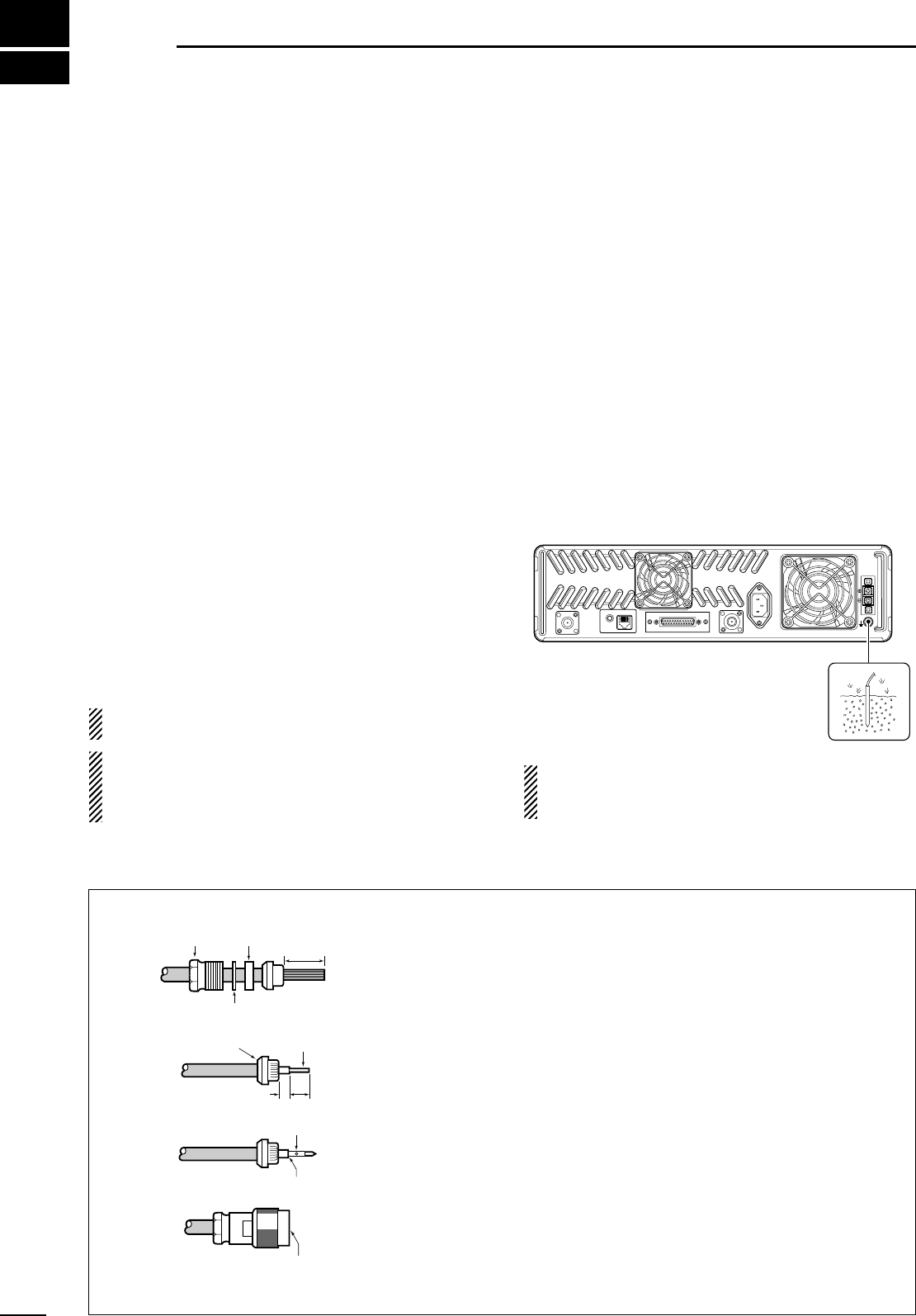
■Grounding
To prevent electrical shock, television interference
(TVI), broadcast interference (BCI) and other prob-
lems, ground the transceiver through the [GND] termi-
nal on the rear panel.
For best results, connect a heavy gauge wire or strap
to a long earth-sunk copper rod. Make the distance be-
tween the [GND] terminal and ground as short as pos-
sible.
RWARNING: NEVER connect the [GND] terminal
to a gas or electric pipe, since the connection could
cause an explosion or electric shock.
TX/TX•RX
EXT SP REMOTE
ACC RX
GND
AC
BATTERY
TYPE-N CONNECTOR INSTALLATION EXAMPLE
30 mm ≈9⁄8in 10 mm ≈3⁄8in 1–2 mm ≈1⁄16 in
Slide the nut, flat washer, rubber gasket and clamp over the coaxial
cable, then cut the end of the cable evenly.
Strip the cable and fold the braid back over the clamp.
Soft solder the center conductor. Install the center conductor pin and
solder it.
Carefully slide the plug body into place aligning the center conductor
pin on the cable. Tighten the nut onto the plug body.
q
w
e
r
15 mm
3 mm 6 mm
No space
Solder hole
Be sure the center conductor is
the same height as the plug body.
Clamp Center
conductor
Washer
Nut Rubber gasket
6
2
INSTALLATION AND CONNECTIONS
TX/TX•RX
EXT SP REMOTE
ACC RX
GND
AC
BATTERY
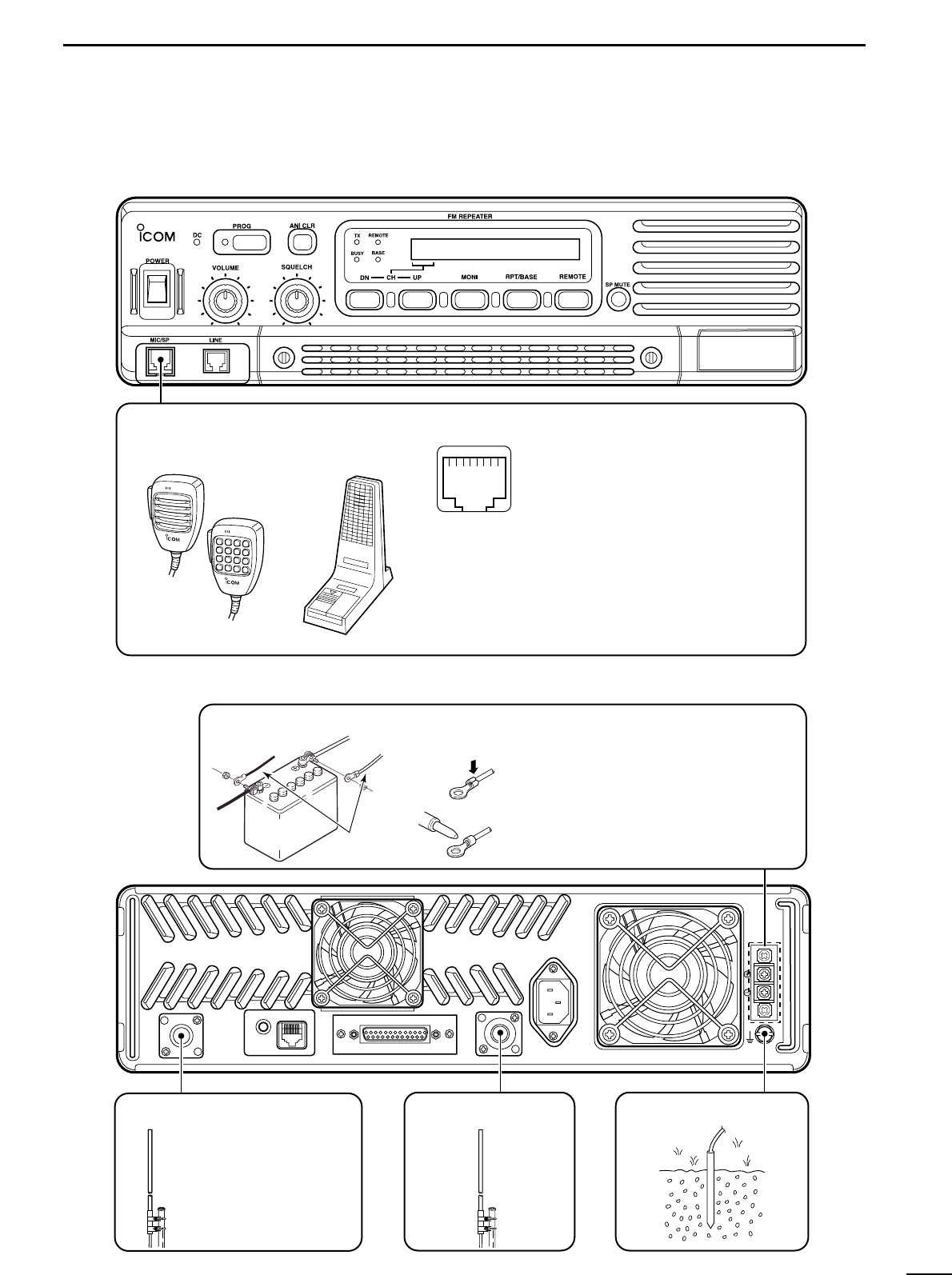
[TX(TX•RX) ANT] (p. 5) [RX ANT] (p. 5)
TX•RX antenna required
for installing an internal
duplexer.
GROUND (p. 5)
[DC POWER INPUT TERMINAL] (p. 8)
12 V
battery Supplied
DC power cable
+ red
_ black Crimp
Solder
SM-25 DESKTOP
MICROPHONE
(optional)
MICROPHONE CONNECTOR (Front panel view)
HM-100N/TN HAND
MICROPHONE
(optional) q +9 V DC output (Max. 10 mA)
w I/O port for PC programming
e Speaker output
r M PTT (Input port for TX control)
t Microphone ground
y Microphone input
u Speaker ground
i M MONI (Input port for monitor control)
qi
CAUTION: DO NOT short pin 1 to ground as this can
damage the internal 9 V regulator. DC voltage is applied
to pin 1 for microphone operation. Take care when
using a non-Icom microphone.
Make sure the back up battery is correctly
connected. Use a cable with following
current capacity. Solder or clamp the cable
lug when connecting the power cable to the
backup battery to prevent voltage drops.
Power cable current capacity: 25 A or more
■Required connections
7
2INSTALLATION AND CONNECTIONS
TX/TX•RX
EXT SP REMOTE
ACC RX
GND
AC
BATTERY
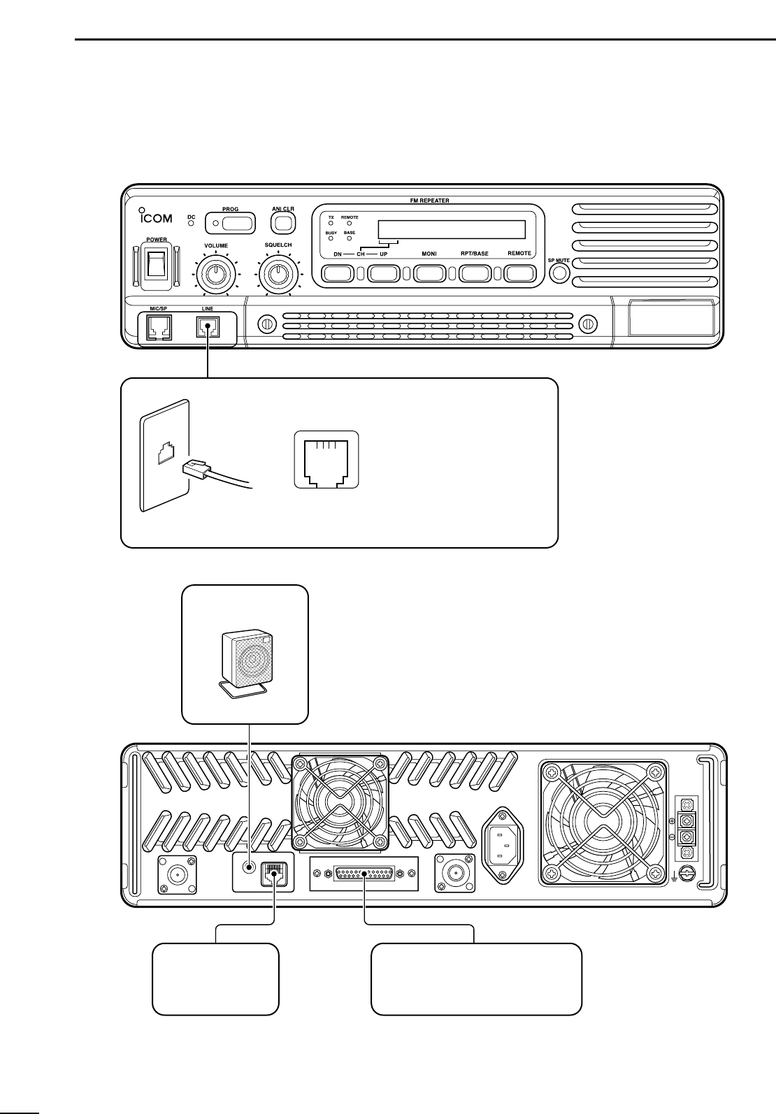
EXTERNAL
SPEAKER
sp-7
icom
Use a 4 Ω speaker.
[REMOTE] (p. 3) ACC CONNECTOR (pgs. 3, 4)
Used for external
equipment control.
Used for external equipment control.
LINE CONNECTOR (Front panel view)
q NC (No connection)
w L1 input/output
e L2 input/output
r NC (No connection)
qr
TEL
* This illustration is example only.
Telephone connector type is different for some countries.
■Advanced connections
8
2
INSTALLATION AND CONNECTIONS
■Power
Make sure the [POWER] switch is turned OFF when
connecting an AC power cable and a backup battery
(emergency power supply).
The IC-FR4000 series can operate with an AC or DC
power supply. If AC power is interrupted when operat-
ing the repeater with an AC power supply, power is au-
tomatically provided to the [BATTERY] terminals.
NOTE: When repeat to turn the repeater ON and
OFF quickly, the repeater may not turn ON. In this
case turn OFF the power switch and wait for a
while, then turning power ON again.
DIN AC OPERATION
• The [DC] indicator turns OFF.
• Use the supplied AC power cable for connection to a
domestic AC outlet.
• Extension cords should not be used unless ab-
solutely necessary. Using improper extension cords
could result in fire risk.
• Usually the battery is continuously charged with a
small amount of current from an AC power supply
through the regulator circuit in the repeater. Dis-
charging is therefore prevented even if the battery is
not used for a long time.
DIN DC OPERATION
CAUTION: Voltages greater than 16 V DC will dam-
age the repeater. Check the source voltage before
connecting the power cable.
• The [DC] indicator lights up green.
• DO NOT place the backup battery on or near the re-
peater. Lead-acid batteries should be placed at least
5 m (16.4 ft.) away from the repeater. Use a heavy
duty cable to make the connection and be sure both
the positive (red) and negative (black) terminals are
correctly connected.
• After the battery is connected and the [POWER]
switch is ON, the repeater continuously supplies ap-
prox. 1 A for charging the battery. If the repeater
stops functioning while connected to the battery, dis-
connect the battery, recharge it, then connect the bat-
tery to continue operation after the battery is charged.
During repeater transmission, approx. 17 A of battery
power is consumed.
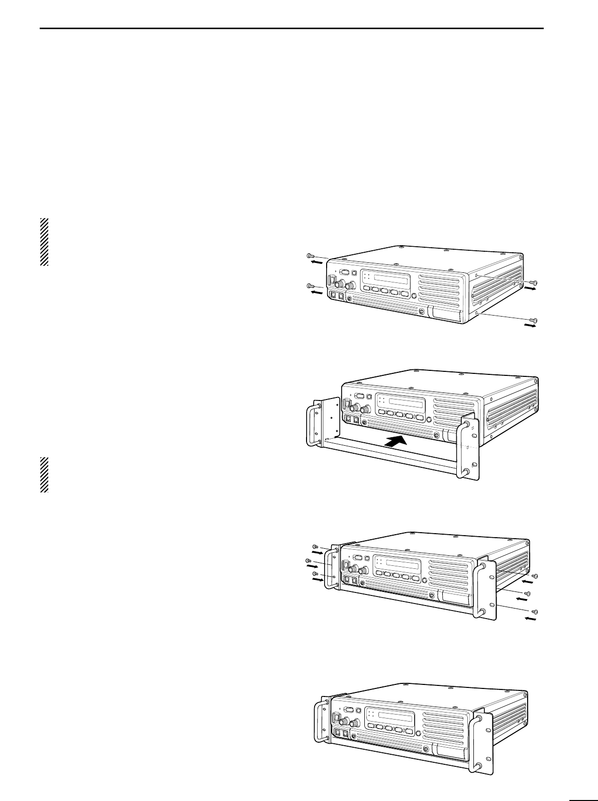
■Mounting the repeater
DUsing the optional MB-78
An optional MB-78 19
INCH RACK MOUNT BRACKET
is
available for mounting the repeater into a 19 inch rack.
The MB-78 can install the repeater’s bottom side and
top side.
• Bottom side installation
qRemove the 2 screws (M4 ×8) from both side of the
side panel (front-end).
wAttach the MB-78 to the bottom side of the repeater.
eTighten the 1 supplied screws (M4 ×8) and 2 re-
moved screws to each side. (6 screws at total)
rThe completed bottom side installation should look
like below.
9
2INSTALLATION AND CONNECTIONS
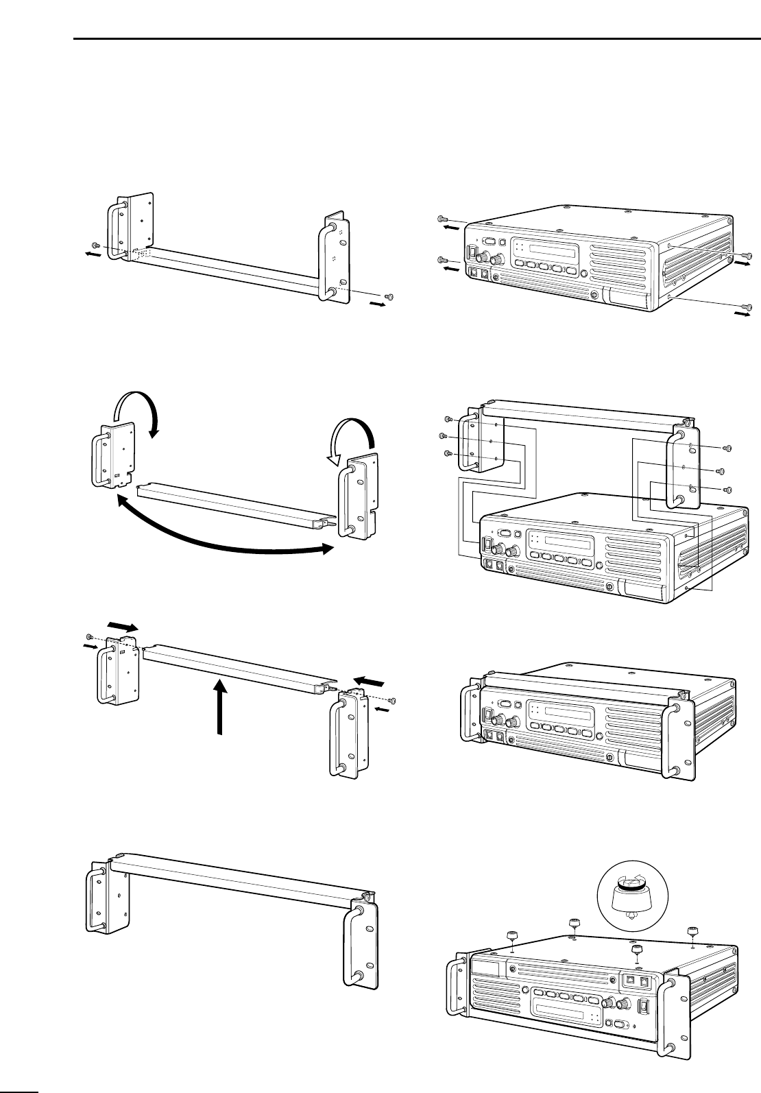
• Top side installation
qRemove the 1 screw (M4 ×8) from both side of the
MB-78.
wRemove the handles from bottom bar. And turn the
handles upside down, then replace the handles
right side and left side.
eAttach the handles to the bar, then tighten the
screws.
rThe completed MB-78 should look like below.
tRemove the 2 screws (M4 ×8) from both side of
the side panel (front-end).
yAttach the MB-78 to the top side of the repeater.
Then tighten the 1 supplied screws (M4 ×8) and 2
removed screws to each side. (6 screws at total)
uThe top side installation should look like below.
iTurn the repeater upside down, then removing the
4 legs for mounting the 19 inch rack.
10
2
INSTALLATION AND CONNECTIONS
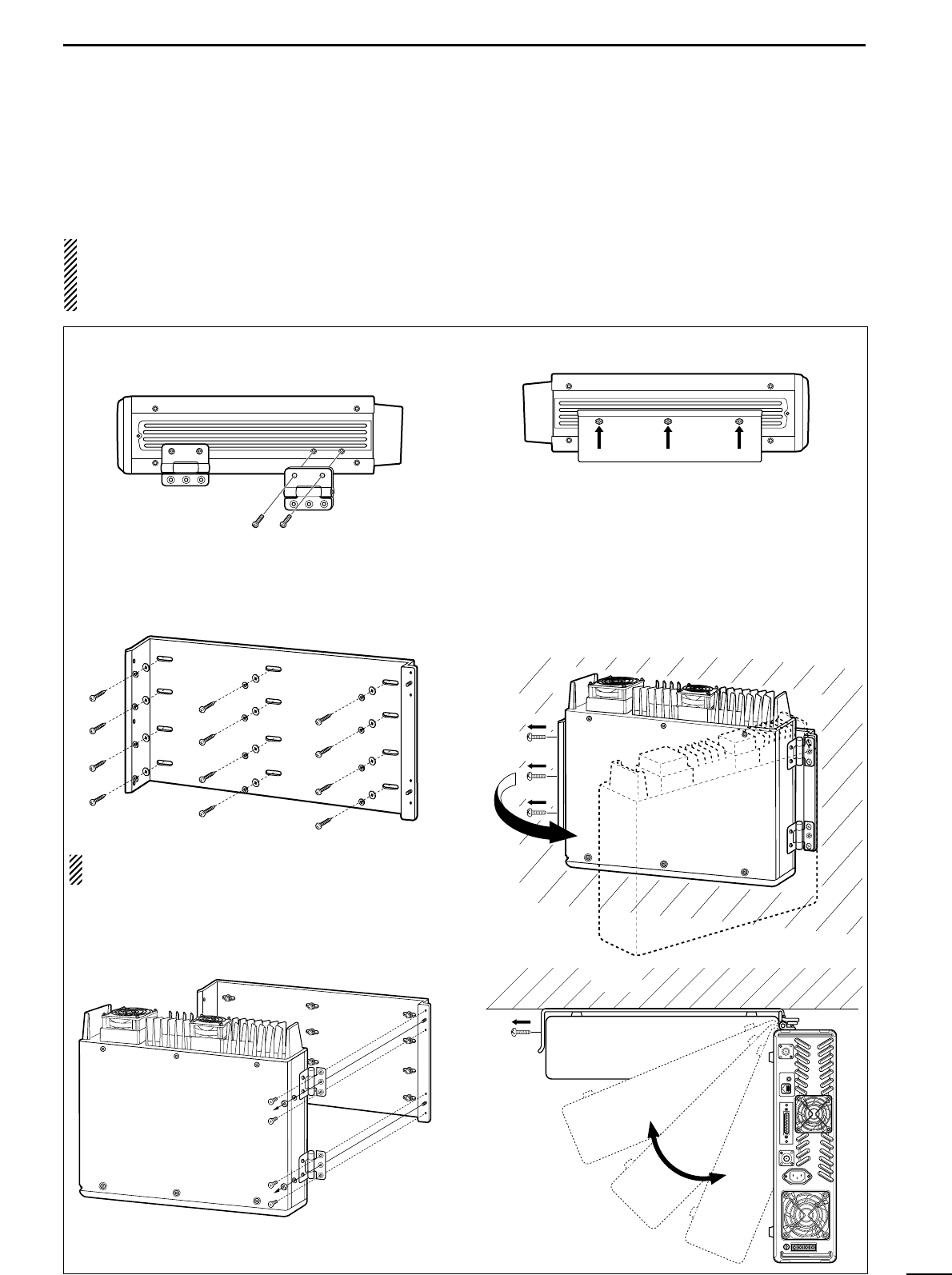
DUsing the optional MB-77
An optional MB-77
WALL MOUNT BRACKET
is available
for mounting the repeater to a flat surface.
RWARNING: NEVER mount the repeater on the
MB-77 by yourself. At least two people are required
to mount the repeater since it weights approx. 12
kg (26 lb).
•Mount the MB-77 securely with the 12 supplied
screws (M6 ×30) to a surface which is more than 50
mm thick and can support more than 20 kg. The unit
must be mounted on a flat hard surface only.
qAttach the hinges at right side of the repeater as
shown below.
wTighten the 2 supplied screws (M5 ×12) for each.
ePut the MB-77 on the wall (or wherever you plan to
mount the repeater).
rTighten the 12 supplied screws (M6 ×30) using flat
washers and spring washers.
NOTE: Put this way to repeater’s front panel will be
bottom side.
tAttach the hinges with repeater to MB-77 and
tighten the 4 supplied screws (M5 ×10) and 2 nuts
(with spring washer).
yTighten the 3 supplied screws (M5 ×12) to other
side.
• For setting up the repeater with MB-77
qRemove the 3 screws (M5 ×12) at left side of the
MB-77 when repeater’s front panel is bottom side.
wPull the left side of the repeater.
eRemove the screws and open the bottom cover or
top cover of the repeater, then set the repeater up.
rReturn the top or bottom cover of the repeater and
MB-77 to their original positions.
TOP VIEW
Wall
3
11
OPTIONAL UNIT INSTALLATION
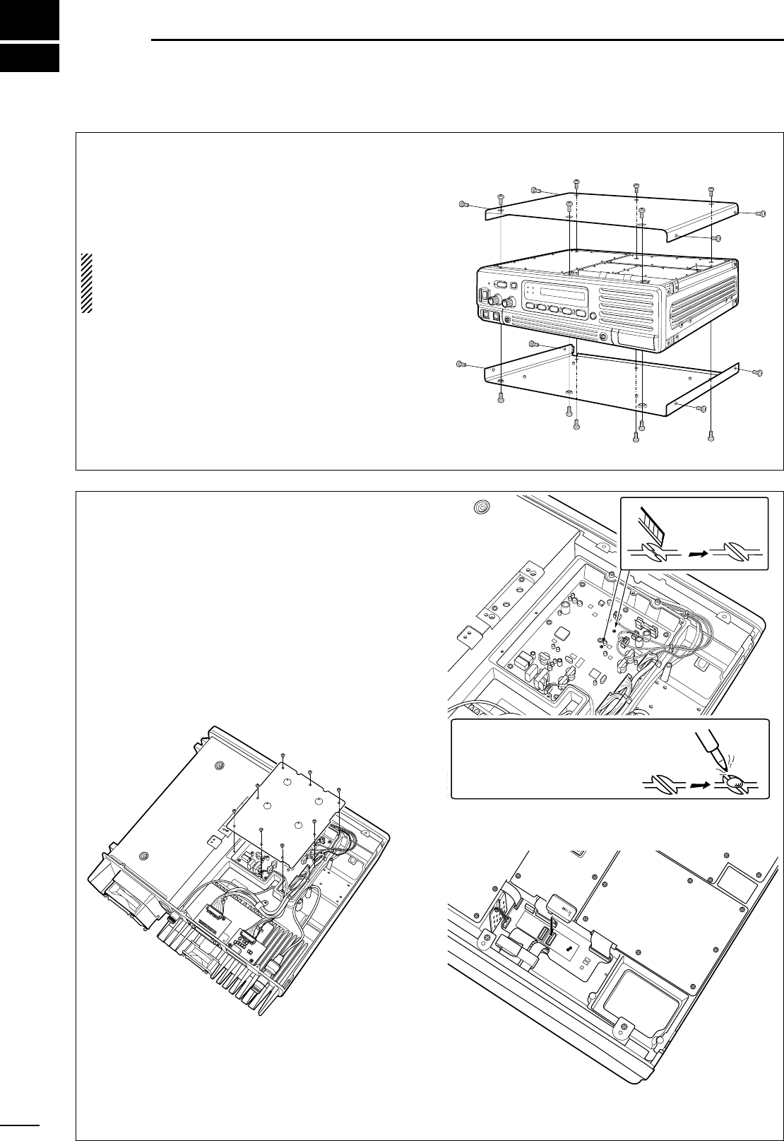
■Opening the repeater’s case
Follow the case and cover opening procedures shown
here when an optional unit is installed or adjust the in-
ternal units, etc.
CAUTION: DISCONNECT the AC power cable
and/or DC power cable from the repeater. Other-
wise, there is danger of electric shock and/or equip-
ment damage.
qRemove 6 screws from the top of the repeater and
4 screws from the sides, then lift up the top cover.
wTurn the repeater upside down.
eRemove 6 screws from the bottom of the repeater,
and 4 screws from the sides, then lift up the bot-
tom cover.
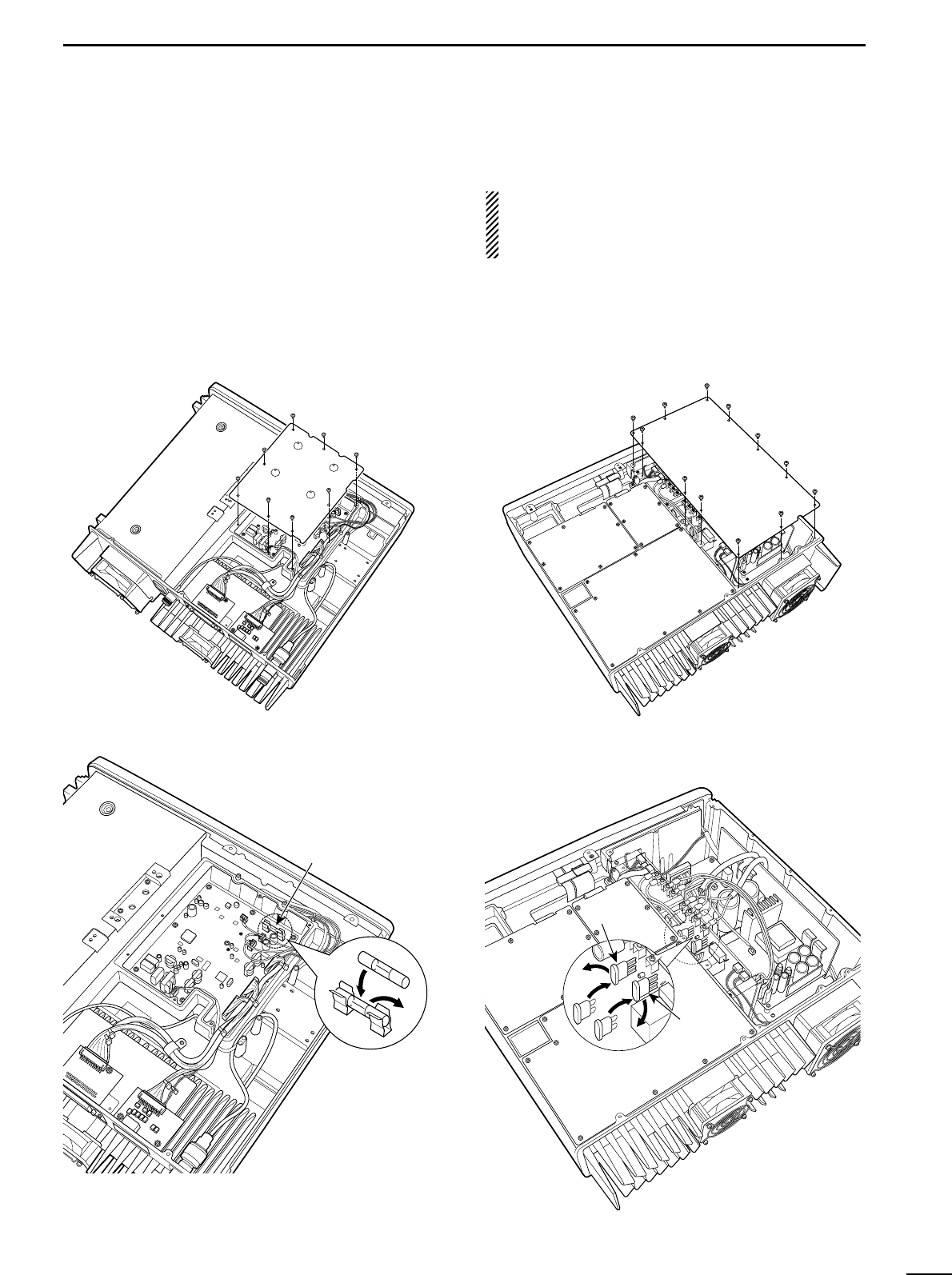
■Voice scrambler unit
installation
The UT-109 (#01)/UT-110 (#01) provides high perfor-
mance private communication for base operating
mode. In order to receive or send scrambled trans-
missions, the UT-109 (#01)/UT-110 (#01) must be in-
stalled and to activate the scrambler function.
qRemove the top and bottom covers as shown
above.
wRemove 8 screws from the LOGIC shielding plate,
then remove the plate.
eCut the pattern on the PCB at the RX AF circuit
(CP1) and TX mic circuit (CP2) on the LOGIC unit
as shown at right.
rTurn the repeater upside down, then install the
scrambler unit as shown below.
tReturn the LOGIC shielding plate, top and bottom
covers to their original positions.
NOTE: Be sure to re-solder
above disconnected points,
otherwise no TX modulation or
AF output is available when
you remove the scrambler unit.

4
12
OPERATION
■Turning power ON
qPush [POWER] to turn power ON.
wIf the repeater is programmed for a power on pass-
word by an Icom Dealer, input digit codes directly.
• The keys in the table below can be used for password
input.
• The repeater detects numbers in the same block as
identical. Therefore “01234” and “56789” are the same.
eWhen the “PASSWORD” indication does not clear
after inputting 4 digits, the input code number may
be incorrect. Turn power off and start over in this
case.
■Receiving and transmitting
DReceiving
qPush [POWER] to turn power ON.
wSet the audio and squelch levels.
➥Rotate [SQUELCH] fully counterclockwise in ad-
vance.
➥Rotate [VOLUME] to adjust the audio output level.
➥Rotate [SQUELCH] clockwise until the noise dis-
appears.
ePush [UP] or [DN] to select the desired channel.
•When receiving a signal, BUSY indicator turns ON and
audio is emitted from the speaker.
•Further adjustment of [VOLUME] to a comfortable listen-
ing level may be necessary at this point.
DTransmitting
qTake the microphone off hook.
wWait for the channel to become clear.
ePush and hold [PTT] to transmit, then speak into the
microphone at your normal voice level.
rRelease [PTT] to receive.
IMPORTANT:
To maximize the readability of the transmitted signal:
(1) Pause briefly after pushing [PTT].
(2) Hold the microphone 1 to 2 inch (2.5 to 5 cm) from
your mouth, then speak into the microphone at a
normal voice level.
■Set mode
DEntering the set mode
qPush [POWER] to turn power OFF, if repeater
power is ON.
wWhile pushing [PROG], [ANI CLR] and [DN], turn
power ON.
eAfter repeater emits beep “Pi,” release [PROG],
[ANI CLR] and [DN], then push [PROG] again.
rAfter repeater emits beep “Pi Pi,” release [PROG] to
enter the set mode.
DReturn to the normal operating mode
qPush [POWER] to turn power OFF, if repeater
power is ON.
wThen turn power ON to return to the normal operat-
ing mode.
DSet mode contents
• S01 LW RPTSQL : Noise squelch threshold level
on the repeater operation
• S02 LW POWER : Transmit Low power setting
• S03 HW POWER : Transmit High power setting
• S04 LN AFDEV : AF deviation for narrow band-
width
• S05 LW AFDEV : AF deviation for wide bandwidth
• S06 LN TONEDEV : Continuous tone deviation for
narrow bandwidth
• S07 LW TONEDEV: Continuous tone deviation for
wide bandwidth
• S08 LN ETONE : External tone deviation for nar-
row bandwidth
• S09 LW ETONE : External tone deviation for wide
bandwidth
• S10 LN RPTAF : AF deviation for narrow band-
width on the repeater operation
• S11 LW RPTAF : AF deviation for wide bandwidth
on the repeater operation
L: Low power, H: High power,
W: Wide bandwidth, N: Narrow bandwidth
KEY
[DN] [UP] [MONI]
[RPT/BASE]
[REMOTE]
NUMBER 012 3 4
567 8 9

5
13
MAINTENANCE
PROBLEM POSSIBLE CAUSE SOLUTION REF.
■Troubleshooting
The following chart is designed to help correct prob-
lems which are not equipment malfunctions.
If you are unable to locate the cause of a problem or
solve it through the use of this chart, contact the near-
est Icom Dealer or Service Center.
Power does not come on
when [POWER] switch is
ON.
No sounds from the
speaker.
Sensitivity is low and
only strong signals are
audible.
Received signal cannot
be understood.
Output power is too low.
No contact possible with
another station.
<DC operation>
• DC power cable is improperly connected.
<AC/DC common>
• Fuse is blown.
• Volume level is too low.
• The squelch is closed.
• The audio mute function is activated.
•A selective call or squelch function is acti-
vated such as 2/5 tone call or tone squelch.
• While in base operating mode, the repeater
is in the transmitting condition.
• Antenna feedline or the antenna connector
has a poor contact or short-circuited.
• Optional voice scrambler is turned OFF.
• Scrambler code is not set correctly.
• Output power is set to Low.
• The other station is using tone squelch.
• While in base operating mode, the repeater
is set to duplex.
• Re-connect the DC power cable correctly.
• Check the cause, then replace the fuse with
a spare one. (Fuses are installed in the inter-
nal REG unit and LOGIC unit.)
• Rotate [VOLUME] clockwise to obtain a suit-
able listening level.
•While in base operating mode, rotate
[SQUELCH] to counterclockwise to open the
squelch.
• While in repeater operating mode, adjust the
squelch threshold level on the set mode to
open the squelch.
• Push [SP MUTE] to the audio mute function
OFF
• Turn the appropriate function OFF.
• Push [PTT] on the microphone to receive or
check the PTT line of an external unit, if con-
nected.
•Check and re-connect (or replace if neces-
sary), the antenna feedline or antenna con-
nector.
• Turn the optional voice scrambler ON.
• Reset the scrambler code.
•Push channel selector to select the high
power operating channel.
• Turn the tone squelch function ON.
•Set the repeater to simplex, when other
transceiver is set to simplex.
p. 6
p. 14
p. 12
p. 12
p. 12
p. 1
–
–
p. 5
–
–
p. 1
–
–
14
5
MAINTENANCE
■Fuse replacement
If a fuse blows or the repeater stops functioning, try to
find the source of the problem, and replace the dam-
aged fuse with a new, rated fuse.
CAUTION: DISCONNECT the AC power cable
and/or DC power cable from the repeater. Other-
wise, there is danger of electric shock and/or equip-
ment damage.
DLOGIC unit
qRemove the bottom cover as shown on p. 11.
wRemove 8 screws from the LOGIC shielding plate,
then remove the plate.
eReplace the circuitry fuse as shown below.
r
Return the LOGIC shielding plate and bottom cover.
For ACC connector
DREG unit
qRemove the top cover as shown on p. 11.
wRemove the 12 screws from the REG shielding
plate, then remove the plate.
eReplace the circuitry fuse as shown below.
rReturn the REG shielding plate and top cover.
For AC line
For DC line

6
15
SPECIFICATIONS AND OPTIONS
■Specifications
Specifications are measured in accordance with TIA603.
DDGeneral
• Frequency coverage : 400.000–430.000 MHz
430.000–450.000 MHz
450.000–480.000 MHz
480.000–512.000 MHz
• Channel specing : 12.5/25.0 kHz type
• PLL channel step : 5.0, 6.25 kHz
• Frequency stability : ±1.5 ppm*/±2.5 ppm*
* Depends on version
• Number of channels : Max. 32 channel
• Antenna connector : SO-239 ×2 (50 Ω)
• Operating temp. range : –30°C to +60°C
(–22°F to +140°F)
• Power supply voltage : 100–120 V AC (50/60 Hz)*
220–240 V AC (50/60 Hz)*
13.6 V DC (negative ground)
* Depends on version
• Current drain (at 13.6 V) : TX high (50 W) 20.0 A typical
Max. audio 2.0 A typical
Stand-by 1.0 A typical
• Dimensions : 410(W) ×110(H) ×360(D) mm
(Projections not included) 6(W)×25⁄8(H) ×51⁄2(D) in
• Weight (approx.) : 12 kg; 26 lb 7 oz
DDTransmitter
• RF output power : 50 W
• Modulation system : Variable reactance frequency
modulation system
• Max. frequency deviation : ±5.0 kHz (Wide),
±2.5 kHz (Narrow)
• Spurious emissions : –70 dBc typical
• Adjacent channel power : More than 70 dB (Wide),
More than 60 dB (Narrow)
• Audio harmonic distortion : 3.0% typical
(at 1 kHz, 40% deviation)
• Hum and noise : More than 40 dB (Wide),
More than 34 dB (Narrow)
• Microphone impedance : 600 Ω(8-pin modular)
DDReceiver
• Receive system : Double conversion
superheterodyne system
• Sensitivity (12 dB SINAD) : 0.25 µV typical
• Intermediate frequencies : 1st; 70.0 MHz, 2nd; 455 kHz
•
Adjacent channel selectivity
: More than 70 dB (Wide),
More than 60 dB (Narrow)
• Spurious response : More than 70 dB
• Intermodulation : More than 70 dB
• Hum and noise : More than 40 dB (Wide),
More than 34 dB (Narrow)
• Audio output power : 2.5 W typical at 10% distortion
with a 4 Ωload
•
External speaker connector
:
2-conductor 3.5 (d) mm (1⁄8") 8 Ω
■Options
•MB-77 WALL MOUNT BRACKET (p. 10)
For mounting the repeater to a wall.
•MB-78 WALL MOUNT (pgs. 9, 10)
For mounting the repeater into a 19 inch rack.
•HM-100N HAND MICROPHONE
•HM-100TN DTMF MICROPHONE
Hand microphone with a DTMF keypad.
•SM-25 DESKTOP MICROPHONE
•UT-109 (#01) VOICE SCRAMBLER UNIT (p. 11)
Non-rolling type (max. 32 codes).
•UT-110 (#01) VOICE SCRAMBLER UNIT (p. 11)
Rolling type (max. 1020 codes).
The scrambler systems of the UT-109 and UT-110 are not
compatible with each other.
All stated specifications are subject to change without
notice or obligation.

MEMO

Count on us!
1-1-32 Kamiminami, Hirano-ku, Osaka 547-0003 Japan
A-6228H-1EX
Printed in Japan
© 2003 Icom Inc.