ICOM orporated 262200 Mobile VHF Transceiver User Manual IC F111 F121 F211 F221
ICOM Incorporated Mobile VHF Transceiver IC F111 F121 F211 F221
UserManual.wiki
>
ICOM orporated
>
262200 User Manual
Manual
Navigation menu
Upload a User Manual
Namespaces
Wiki Guide
HTML
PDF
Info
Views
User Manual
Discussion / Help
Navigation
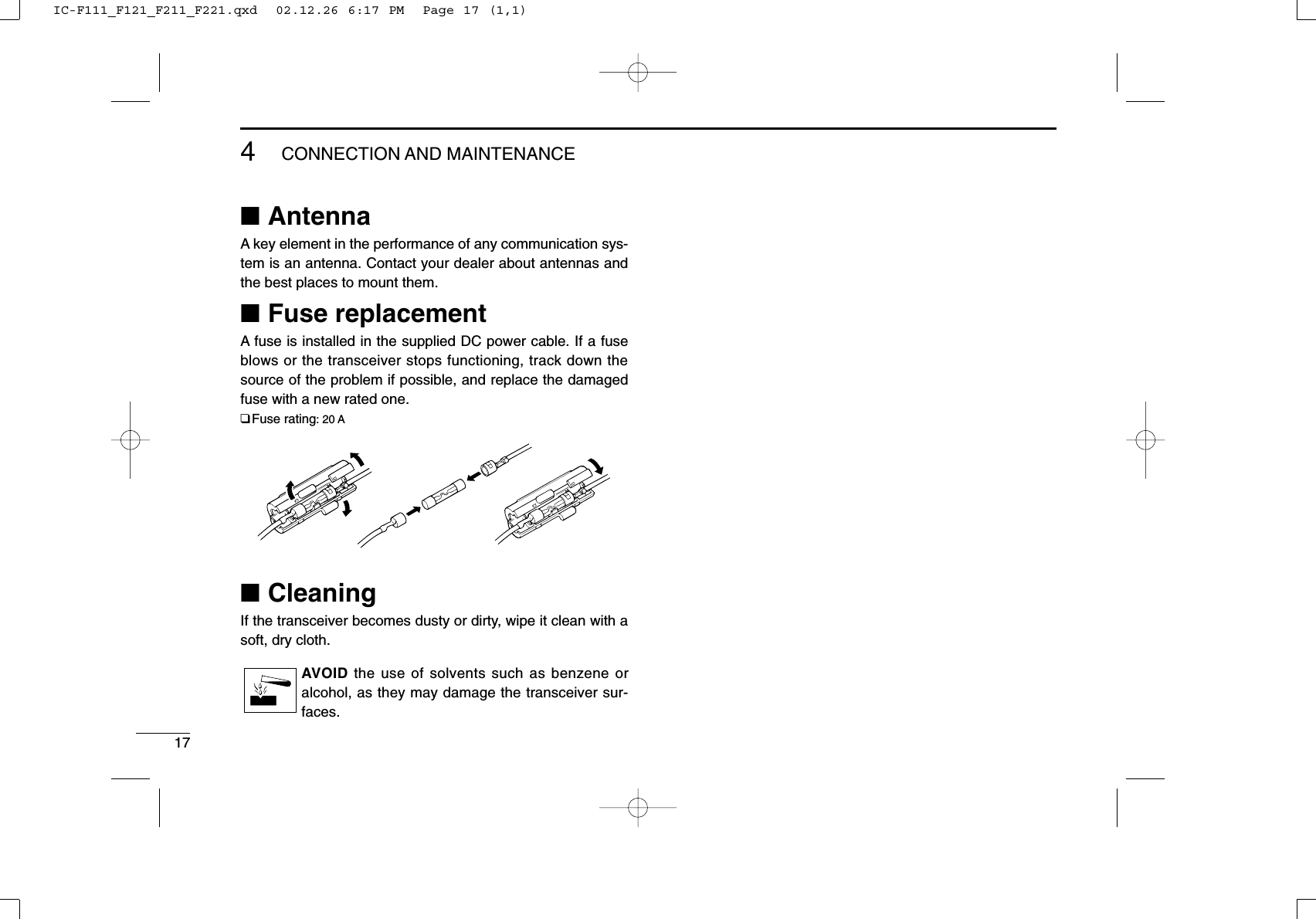
![11PANEL DESCRIPTIONytrqwe■Front panelqAF VOLUME CONTROL KNOBRotate the knob to adjust the audio output level.• Minimum audio level is pre-programmed.wFUNCTION DISPLAYDisplays a variety of information, such as an operatingchannel number/name, 5-tone code, DTMF numbers andaudible condition, etc.NOTE: The above functions depend on pre-programming.eUP/DOWN [ ]/[ ] KEYS➥Push to select the operating channel.➥Can be programmed for one of several functions by yourdealer. (Same as [P0] to [P3] keys)rPOWER SWITCH [POWER]Push to turn the power ON and OFF.• The following functions are available at power ON as options:- Automatic scan start- Password prompt- Set modeIC-F111_F121_F211_F221.qxd 02.12.26 6:17 PM Page 1 (1,1)](https://usermanual.wiki/ICOM-orporated/262200/User-Guide-299694-Page-4.png)
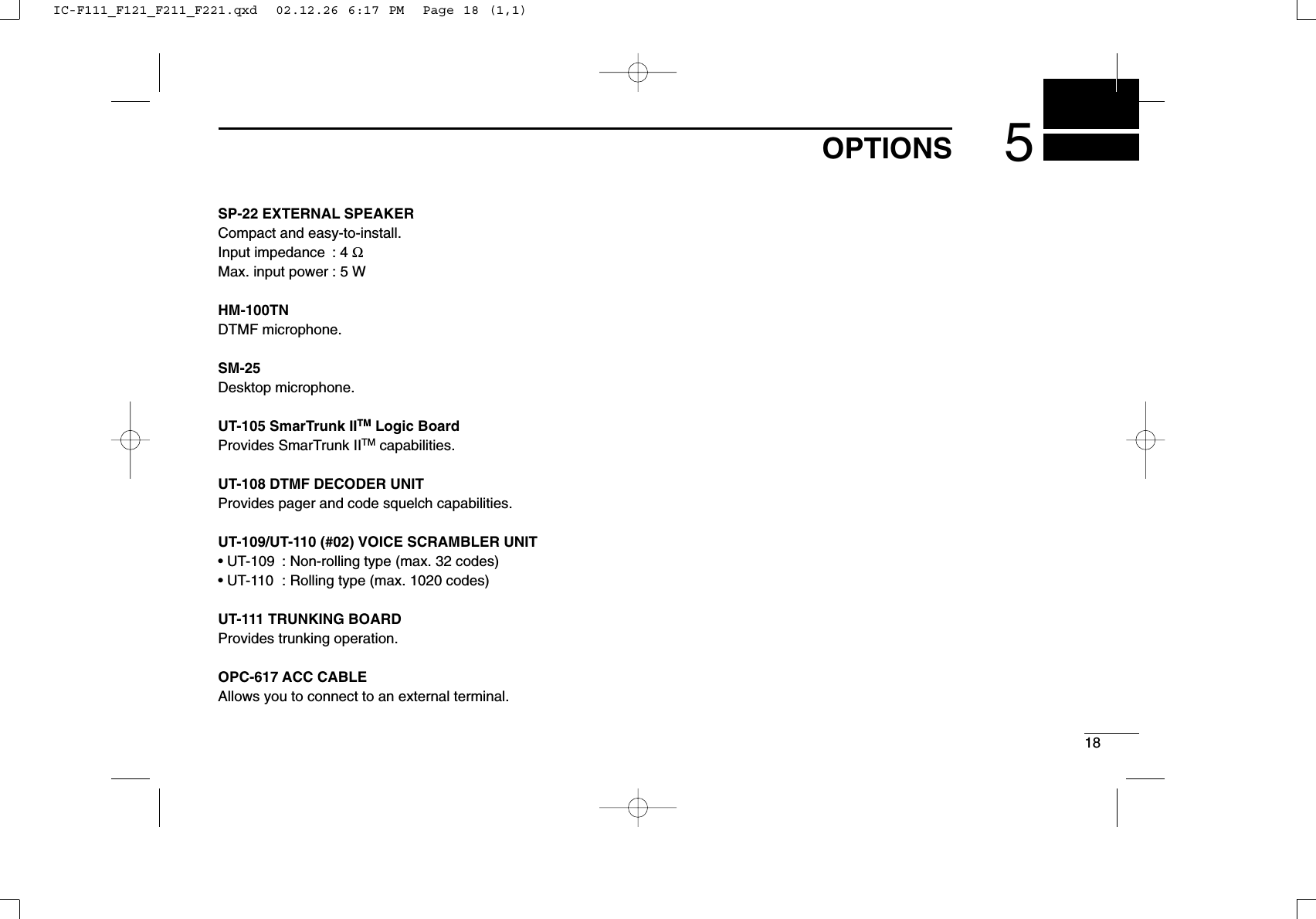
![21PANEL DESCRIPTIONtDEALER-PROGRAMMABLE KEYS [P0] to [P3]Desired functions can be programmed independently byyour dealer.yMICROPHONE CONNECTORConnect the supplied microphone or optional DTMF micro-phone for SmarTrunk IITM operation here.NEVER connect non-specified microphones. The pinassignments may be different and the transceiver maybe damaged.DDMICROPHONEThe supplied microphone has a PTT switch and a hangerhook.• The following functions are available when the microphone is on oroff hook:- Automatic scan start when on hook.- Automatic priority channel selection when off hook.- Sets to ‘Inaudible’ condition (mute condition) when on hook.- Sets to ‘Audible’ condition (unmute condition) when off hook.■Function displayqTRANSMIT INDICATORAppears while transmitting.wBUSY INDICATORAppears while the channel is busy.eSIGNAL STRENGTH METERIndicates relative receive signal strength level.rLOW POWER INDICATORAppears when low output power is selected.tAUDIBLE INDICATORAppears when the channel is in the ‘Audible’ condition(unmute condition).ySCRAMBLER INDICATORAppears when the scrambler function is activated. (OptionalUT-109 (#02)/UT-110 (#02) SCRAMBLER UNIT is required.)qwertyuiIC-F111_F121_F211_F221.qxd 02.12.26 6:17 PM Page 2 (1,1)](https://usermanual.wiki/ICOM-orporated/262200/User-Guide-299694-Page-5.png)
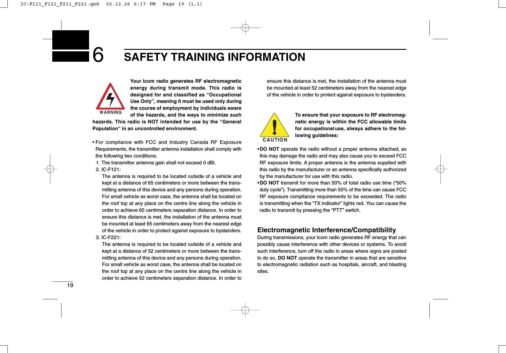
![31PANEL DESCRIPTIONu2/5TONE INDICATORAppears when the specified 2/5-tone call is received.iALPHANUMERIC DISPLAYDisplays the CH number, 5-tone indication, DTMF num-bers, Audible indication, etc.NOTE: When the alphanumeric display blinks and trans-mitting becomes impossible, check that the DC batteryvoltage has not dropped below 8 V or that the antenna isnot tuned properly or the antenna connection is faulty.■Programmable function keysThe following functions can be assigned to [P0], [P1], [P2],[P3], [ ] and [] programmable function keys.Consult your Icom dealer for details concerning your trans-ceiver’s programming.In the following explanations, programmable function namesare bracketed. The specific switch used to activate the func-tion depends on programming.¡¡CH UP AND DOWN KEYS➥Select an operating channel.➥Select a transmit code channel after pushingthe [TX CH] key.➥Select a DTMF channel after pushing the[DTMF] key.➥Select a scan group after pushing and holdingthe [SCAN] key.¡¡BANK KEYSelect and determine a bank number.• When the optional UT-105 is installed, push one ormore times to select a channel bank for conventionalchannels or SmarTrunk II TM channels.CH UPCH DNBANKIC-F111_F121_F211_F221.qxd 02.12.26 6:17 PM Page 3 (1,1)](https://usermanual.wiki/ICOM-orporated/262200/User-Guide-299694-Page-6.png)
, [MONI]and[EMER]keys.MONISCAN ASCAN BLOCKIC-F111_F121_F211_F221.qxd 02.12.26 6:17 PM Page 4 (1,1)](https://usermanual.wiki/ICOM-orporated/262200/User-Guide-299694-Page-7.png)
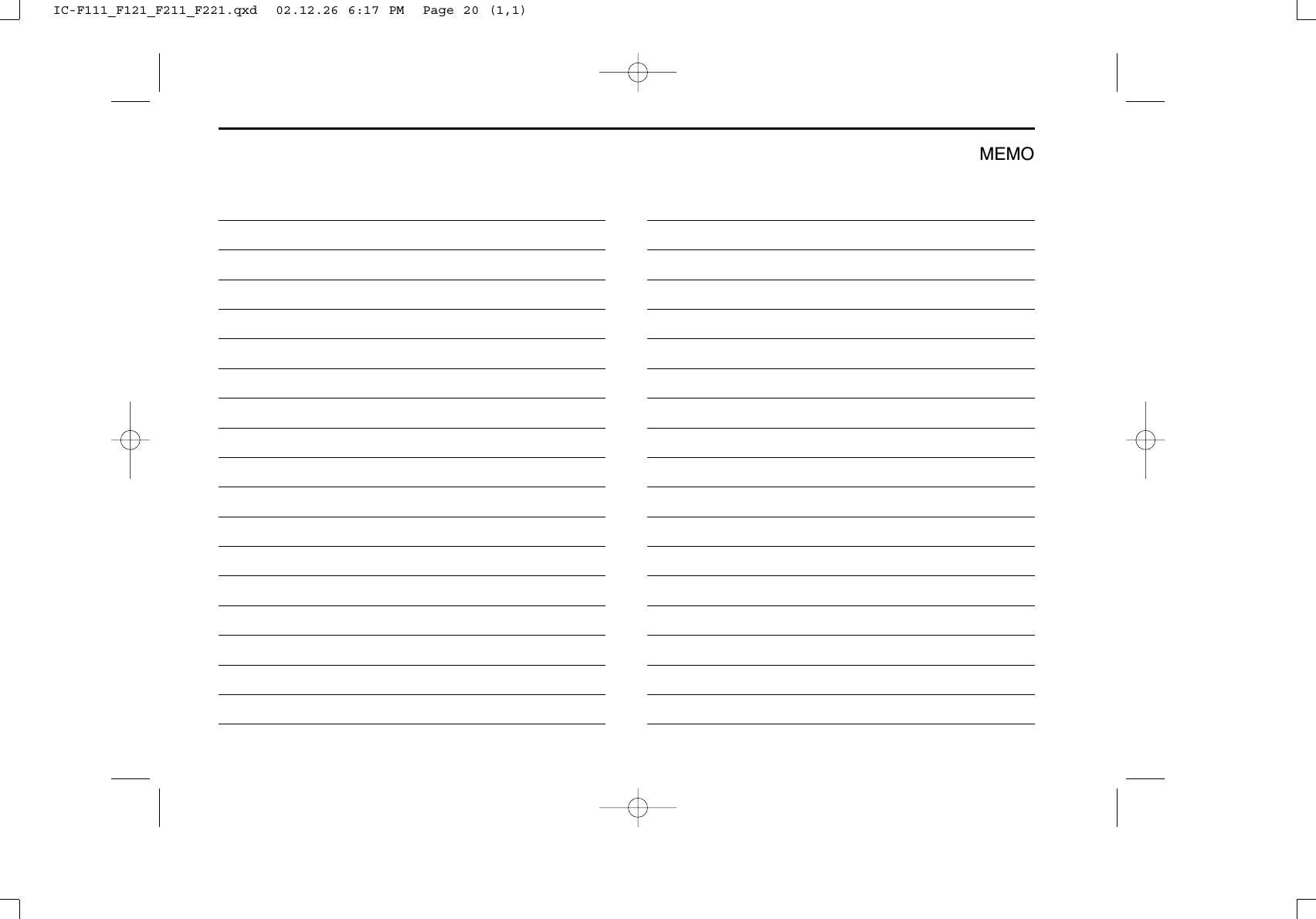
![51PANEL DESCRIPTION¡¡OUTPUT POWER SELECTION KEYSSelect the transmit output power temporarily, orpermanently, depending on the pre-setting.• Contact your dealer for the output power level for eachselection.¡¡TALK AROUND KEYTurns the talk around function ON and OFF.• The talk around function equalizes the transmit fre-quency to the receive frequency for mobile-to-mobilecommunication.¡¡WIDE/NARROW KEYPush this key to toggle the bandwidth betweenwide or narrow.¡¡DTMF AUTODIAL KEYPush this key to display the text of the DTMFchannel number and set the desired channelnumber via the []/[]key. Then, push thiskey again to transmit a specified DTMF code.TAW/N¡¡CALL KEYTransmit a 2-tone, 5-tone code.• Call transmission is necessary before you call anotherstation depending on your signaling system.• The [CAL A] and/or [CAL B] keys may be availablewhen your system employs selective ‘Individual/Group’calls. Contact your dealer about which call is assignedto each key.¡¡EMERGENCY KEYPush and hold the key to transmit an emergency call.• If you want to cancel the emergency call, push andhold (or push) the key again before transmitting thecall.• Depending on the pre-setting, the emergency call istransmitted one time only, or repeatedly, until receivinga control code.¡¡HOOK SCANWhen the Hook Scan function is turned ON, pushthis key to stop scanning temporarily. Push thiskey again to re-start scanning.¡¡TX CODE KEYSelect a transmit 5-tone code (station code) chan-nel.EMERHOOKH/LCALLCAL ACAL BDTMFTX CHIC-F111_F121_F211_F221.qxd 02.12.26 6:17 PM Page 5 (1,1)](https://usermanual.wiki/ICOM-orporated/262200/User-Guide-299694-Page-8.png)
![61PANEL DESCRIPTION¡¡SCRAMBLER KEY➥Push and hold to turn the voice scrambler func-tion ON.➥Push this key to turn the voice scrambler func-tion OFF.NOTE:• The optional UT-109 (#02) or UT-110 (#02)VOICE SCRAMBLER UNIT is required.– UT-109: Non-rolling type. 32 codes are available.– UT-110: Rolling type. Provides higher communi-cation security. 1020 (4 groups ×255) codes areavailable.• This transceiver requires version #02 ofthese units. Do not install version #01, asthey are not compatible.• Some PC board modifications are requiredwhen installing UT-109 or UT-110. Pleaserefer to ‘Optional UT-109 or UT-110 installa-tion’. (p.16)• Please contact your dealer for details.SCRM¡¡USER SET MODE KEYChanges the contents of the items in the User Setmode. Please refer to p. 10.• Push and hold this key for 1 sec. to enter set mode.Push this key again momentarily to select the desireditem. Push []/[]to set the desired level/condi-tion.Push and hold this key again to exit set mode.• User set mode also available via the ‘Power ON func-tion’.SETIC-F111_F121_F211_F221.qxd 02.12.26 6:17 PM Page 6 (1,1)](https://usermanual.wiki/ICOM-orporated/262200/User-Guide-299694-Page-9.png)
![72OPERATION■Turning power ONqPush [ ] to turn the power ON.wIf the transceiver is programmed for a start up passcode,input the digit codes as directed by your dealer.• The keys in the table below can be used for password input:• The transceiver detects numbers in the same block as identical.Therefore “01234” and “56789” are same.eWhen the “PASSWORD” indication does not clear afterinputting 4 digits, the input code number is incorrect. In thiscase, turn the power off and start over.■Channel selectionSeveral types of channel selection are available. The meth-ods may differ according to your system setup.NON-BANK TYPE:Push []/[]to select the desired operating channel insequence; or, push one of the [CH 1] to [CH 4] keys to selecta channel directly.BANK-TYPE: Push [BANK] to select the desired bank number or name.AUTOMATIC SCAN TYPE:Channel setting is not necessary for this type. When turningthe power ON, the transceiver automatically starts scanning.Scanning stops when receiving a call or when taking themicrophone off hook.KEYNUMBER 0123456789IC-F111_F121_F211_F221.qxd 02.12.26 6:17 PM Page 7 (1,1)](https://usermanual.wiki/ICOM-orporated/262200/User-Guide-299694-Page-10.png)
![82OPERATION■Receiving and transmittingRECEIVING:qPush [ ] to turn the power ON.wPush []and []to select a channel.eWhen receiving a call, adjust the audio output level to acomfortable listening level.TRANSMITTING:rTake the microphone off hook.• 2-tone, 5-tone mute may be released. (The ‘audible’ condition isselected and “ ” appears.)• A priority channel may be selected automatically.tWait for the channel to become clear.• The channel is busy when “ ” appears.yPush the [CALL] key when initiating a call from your side.• Coded audio may be heard from the transceiver, then “ ”appears.• This operation may not be necessary depending on your signal-ing system. Contact your dealer.uWhile pushing and holding [PTT], speak into the micro-phone at your normal voice level.iRelease [PTT] to receive.IMPORTANT!: To maximize the readability of your signal;➥Pause briefly after pushing [PTT].➥Hold the microphone 2 to 5 cm from your mouth, thenspeak into the microphone at a normal voice level.DTransmitting notes• Transmit inhibit functionThe transceiver has several inhibit functions which restricttransmission under the following conditions:- The channel is in mute condition (‘Inaudible’ condition; “ ” doesnot appear).- Channel is busy.- A matched/un-matched CTCSS code is received.- The selected channel is a ‘receive only’ channel.• Time-out timerAfter continuous transmission for a pre-programmed period,the time-out timer is activated causing the transceiver to stoptransmitting and automatically select receive.• Penalty timerOnce the time-out timer is activated, transmission is furtherinhibited for a period determined by the penalty timer.IC-F111_F121_F211_F221.qxd 02.12.26 6:17 PM Page 8 (1,1)](https://usermanual.wiki/ICOM-orporated/262200/User-Guide-299694-Page-11.png)
![92OPERATIONDTX code channel selectionIf the transceiver has a [TX CH] key, the display can be tog-gled between the operating channel number (or name) andTX code channel number (or name). When the TX codechannel number (or name) is displayed, the []/[]keysselect the TX code channel.To select a TX channel:qPush [TX CH]—a TX code channel appears.wPush []/[]to select the desired TX code channel.ePush [CALL] to transmit the selected TX code.rPush [TX CH] again to return to the channel display.DTX code number selectionIf the transceiver has a [TX CH] key, TX code contents can bechanged within the allowable digits.To select a TX code:qPush [TX CH]—a TX code number appears and the firstdigit blinks.wPush []/[]to select the desired number of the blink-ing digit.ePush [TX CH] to enter the selected number and the nextdigit will start blinking automatically.rRepeat step wand eto input all allowed digits.tPush [CALL] to transmit the selected TX code.DDTMF transmissionIf the transceiver has a [DTMF] key, the automatic DTMFtransmission function is available. Up to 7 DTMF channelsmay be available.To transmit a DTMF code:qPush [DTMF]—a DTMF code channel appears.wPush []/[]to select the desired DTMF channel.ePush and hold [DTMF] to transmit the DTMF code on theselected DTMF channel.DScrambler functionThe UT-109 (#02) or UT-110 (#02) optional voice scramblerunit provides high performance private communicationbetween stations with the same scrambler codes.To turn the scrambler function ON and OFF:qPush and hold [SCRM] to turn the scrambler function ON.wPush [SCRM] to turn the function OFF.IC-F111_F121_F211_F221.qxd 02.12.26 6:17 PM Page 9 (1,1)](https://usermanual.wiki/ICOM-orporated/262200/User-Guide-299694-Page-12.png)
![102OPERATIONDUser set modeUser set mode is accessed at power ON and allows you toset seldom-changed settings. In this case you can “cus-tomize” transceiver operation to suit your preferences andoperating style.Entering the user set mode:qWhile pushing and holding []and [], push [POWER]to enter user set mode ON, allowing you to set seldom-changed settings.wPush and hold [P0] to select the appropriate item. Then,push []or []to set the desired level/mode.- Available set mode functions;• Backlight : OFF, Dim, Auto or ON• Beep : OFF or ON• SQL Level : 0 to 255• AF Min level : 0 to 255ePush [POWER] (or push and hold [P0]) again to exit setmode.User set mode is also available via a programmable key.Please refer to p. 6 [SET] section.IC-F111_F121_F211_F221.qxd 02.12.26 6:17 PM Page 10 (1,1)](https://usermanual.wiki/ICOM-orporated/262200/User-Guide-299694-Page-13.png)
![113OPTIONAL SmarTrunk II™OPERATION■SmarTrunk II™and conventional modesThis transceiver is capable of SmarTrunk II™ functions.The optional UT-105 allows communication in conventionalchannels or SmarTrunk II™ channels. Select a channel bankfor SmarTrunk II™ before trunking operation.• Push [BANK]several times to select a channel bank for con-ventional channels or SmarTrunk II™ channels.- Scanning starts when a channel bank for SmarTrunk II™ opera-tion is selected.- Contact your dealer for channel bank details.NOTE: Optional HM-100TN DTMF MICROPHONE isrequired. Contact your dealer for details.■SmarTrunk II™operationThese features are enabled by a dealer and may not be avail-able in your system. Contact your dealer for details.DPlacing a telephone callEnter the phone number followed by [1], [M].• A high-pitched beep indicates that the number is accepted.• When the called party answers, push the [PTT] switch to talk, andrelease it to listen.DCalling another local system subscriberEnter the subscriber number followed by [3], [M].• A high-pitched beep indicates that the number is accepted.• You hear ringing, then two short beeps when the subscriberanswers.• If the other subscriber is on another call or out of range, you hear afast busy signal and the call terminates automatically.DReceiving a callWhen you hear ringing, push [M] to answer.• For a group call, you hear a short ring followed by two short beeps.You do not have to answer a group call to hear it over the air.IC-F111_F121_F211_F221.qxd 02.12.26 6:17 PM Page 11 (1,1)](https://usermanual.wiki/ICOM-orporated/262200/User-Guide-299694-Page-14.png)
![123OPTIONAL SmarTrunk II™ OPERATIONDTerminating a callAfter completing a call, push [#] to disconnect (hang up).IMPORTANT!: If one person in the conversation termi-nates a call, all participants will be cut off.DLast number re-dialPush [M] 2 times to automatically re-dial the last called num-ber.• A high-pitched beep indicates that the number is accepted.DMemory speed-diallingTo automatically dial a commonly used number from memory:• Push [M] followed by the memory location (0–9).DTurbo SpeeDialTo automatically dial a commonly used number with onepush:• Push one of the turbo SpeeDial keys ([A], [B], [C] or [D]).DProgramming memory speed dialqPush and hold [M] until you hear a high-pitched beep.wEnter the memory location (0–9, A, B, C, D), the telephoneor subscriber number, then [1], [M] (or [3], [M] if for anothersystem subscriber).• A high-pitched beep indicates successful programming.• Memories [A]–[D] are used for the Turbo SpeeDial.DSystem busy indicationIf all channels are busy, three low beeps sound after you initi-ate a call. Try the call again later.DPTT dispatch operationqPush [PTT] once (without dialling) to initiate a dispatch call.wBegin talking after you hear three beeps (one short, high-pitched, two very-short, low-pitched).eReceiving a dispatch call is indicated by the same three-beep sequence.• It is not necessary to push [M] to answer a dispatch call.DEmergency callPush [0], [M] to initiate an emergency call.• Contact your dealer for details.DClear channel alertingIf all channels are busy, the transceiver automatically beginssearching for an open channel and beeps every ten seconds.When two short beeps (low-pitched, then high-pitched) areheard, a channel is available. Push [M] two times immediate-ly to re-dial the last number.NOTE: For additional operating instructions, contact yourdealer.IC-F111_F121_F211_F221.qxd 02.12.26 6:17 PM Page 12 (1,1)](https://usermanual.wiki/ICOM-orporated/262200/User-Guide-299694-Page-15.png)