ICOM orporated 262301 Mobile UHF Transceiver User Manual IC F111 F121 F211 F221
ICOM Incorporated Mobile UHF Transceiver IC F111 F121 F211 F221
Manual
INSTRUCTION MANUAL
iF111
VHF TRANSCEIVER
UHF TRANSCEIVER
iF121
iF211
iF221
!IC-F111_F121_F211_F221.qxd 03.2.12 10:02 AM Page a (1,1)

i
IMPORTANT
EXPLICIT DEFINITIONS
RWARNING! NEVER connect the transceiver to an
AC outlet. This may pose a fire hazard or result in an electric
shock.
CAUTION! NEVER touch the transceiver (especially
the heat sink) when transmitting continuously for long peri-
ods. It will become hot.
NEVER connect the transceiver to a power source of more
than 16 V DC such as a 24 V battery. This connection will ruin
the transceiver.
NEVER cut the DC power cable between the DC plug and
fuse holder. If an incorrect connection is made after cutting,
the transceiver might be damaged.
NEVER place the transceiver where normal operation of
the vehicle may be hindered or where it could cause bodily
injury.
NEVER allow children to touch the transceiver.
NEVER expose the transceiver to rain, snow or any liquids.
PRECAUTION
WORD DEFINITION
RWARNING Personal injury, fire hazard or electric shock
may occur.
CAUTION Equipment damage may occur.
NOTE If disregarded, inconvenience only. No risk
of personal injury, fire or electric shock.
READ ALL INSTRUCTIONS carefully and com-
pletely before using the transceiver.
SAVE THIS INSTRUCTION MANUAL— This
instruction manual contains important operating instructions
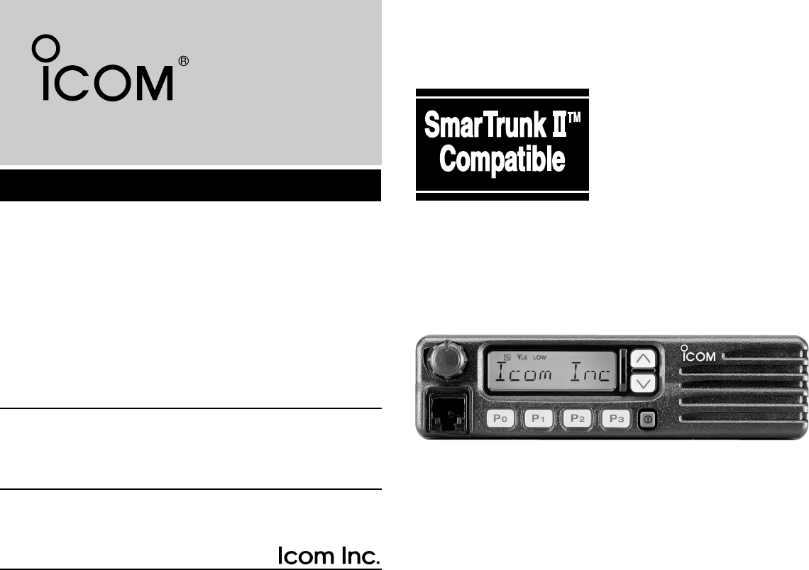
for the IC-F111/F121 VHF TRANSCEIVER and IC-F211/F221
UHF TRANSCEIVER.
Icom, Icom Inc. and the logo are registered trademarks of
Icom Incorporated (Japan) in the United states, the United
Kingdom, Germany, France, Spain, Russia and/or other countries.
SmarTrunk II™ is a trademark of the SmarTrunk Systems, Inc.
!IC-F111_F121_F211_F221.qxd 03.2.12 10:02 AM Page i (1,1)

ii
USE the supplied microphone only. Other microphones
have different pin assignments and may damage the trans-
ceiver.
DO NOT use or place the transceiver in areas with tem-
peratures below –22°F (–30°C) or above +140°F (+66°C), or
in areas subject to direct sunlight, such as the dashboard.
AVOID operating the transceiver without running the vehi-
cle’s engine. The vehicle’s battery will quickly run out if the
transceiver transmits while the vehicle’s engine OFF.
AVOID placing the transceiver in excessively dusty envi-
ronments.
AVOID placing the transceiver against walls. This will
obstruct heat dissipation.
AVOID the use of chemical agents such as benzine or alco-
hol when cleaning, as they damage the transceiver surfaces.
For U.S.A. only
CAUTION: Changes or modifications to this transceiver, not ex-
pressly approved by Icom Inc., could void your authority to operate
this transceiver under FCC regulations.
TABLE OF CONTENTS
IMPORTANT .................................................................................... i
EXPLICIT DEFINITIONS ................................................................. i
PRECAUTION .................................................................................. i
TABLE OF CONTENTS .................................................................. ii
1 PANEL DESCRIPTION ........................................................... 1–6
■Front panel ............................................................................... 1
■Function display ....................................................................... 2
■Programmable function keys .................................................... 3
2 OPERATION .......................................................................... 7–10
■Turning power ON .................................................................... 7
■Channel selection ..................................................................... 7
■Receiving and transmitting ....................................................... 8
DTransmitting notes ................................................................. 8
DTX code channel selection .................................................... 9
DTX code number selection .................................................... 9
DDTMF transmission ............................................................... 9
DScrambler function ................................................................ 9
DUser set mode ..................................................................... 10
3 OPTIONAL SmarTrunk IITM OPERATION .......................... 11–12
■SmarTrunk IITM and conventional modes ............................... 11
■SmarTrunk IITM operation ....................................................... 11
4 CONNECTION AND MAINTENANCE ................................ 13–17
■Rear panel and connection .................................................... 13
■Supplied Accessories ............................................................. 14
■Mounting the transceiver......................................................... 15
■Optional UT-105, UT-108 or UT-111 installation ..................... 15
■Optional UT-109 or UT-110 installation .................................. 16
■Optional OPC-617 installation................................................. 16
■Antenna................................................................................... 17
■Fuse replacement .................................................................. 17
■Cleaning ................................................................................. 17
5 OPTIONS ................................................................................... 18
6 SAFETY TRAINING INFORMATION ........................................ 19
!IC-F111_F121_F211_F221.qxd 03.2.12 10:02 AM Page ii (1,1)
1
1PANEL DESCRIPTION
ytr
qwe
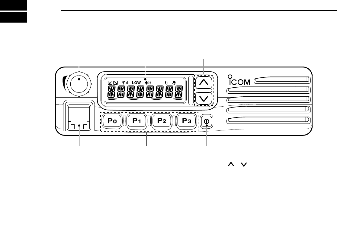
■Front panel
qAF VOLUME CONTROL KNOB
Rotate the knob to adjust the audio output level.
• Minimum audio level is pre-programmed.
wFUNCTION DISPLAY
Displays a variety of information, such as an operating
channel number/name, 5-tone code, DTMF numbers and
audible condition, etc.
NOTE: The above functions depend on pre-programming.
eUP/DOWN [ ]/[ ] KEYS
➥Push to select the operating channel.
➥Can be programmed for one of several functions by your
dealer. (Same as [P0] to [P3] keys)
rPOWER SWITCH [POWER]
Push to turn the power ON and OFF.
• The following functions are available at power ON as options:
- Automatic scan start
- Password prompt
- Set mode
!IC-F111_F121_F211_F221.qxd 03.2.12 10:02 AM Page 1 (1,1)
2
1
PANEL DESCRIPTION
tDEALER-PROGRAMMABLE KEYS [P0] to [P3]
Desired functions can be programmed independently by
your dealer.
yMICROPHONE CONNECTOR
Connect the supplied microphone or optional DTMF micro-
phone for SmarTrunk IITM operation here.
NEVER connect non-specified microphones. The pin
assignments may be different and the transceiver may
be damaged.
DDMICROPHONE
The supplied microphone has a PTT switch and a hanger
hook.
• The following functions are available when the microphone is on or
off hook:
- Automatic scan start when on hook.
- Automatic priority channel selection when off hook.
- Sets to ‘Inaudible’ condition (mute condition) when on hook.
- Sets to ‘Audible’ condition (unmute condition) when off hook.
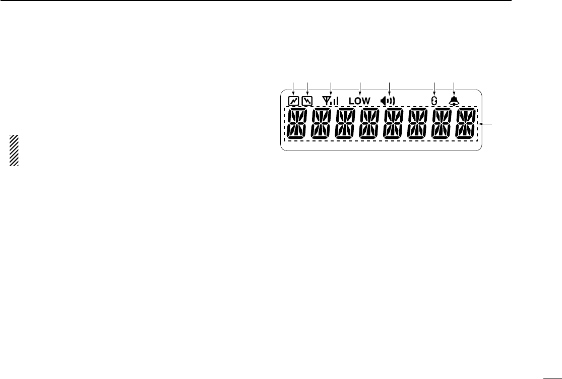
■Function display
qTRANSMIT INDICATOR
Appears while transmitting.
wBUSY INDICATOR
Appears while the channel is busy.
eSIGNAL STRENGTH METER
Indicates relative receive signal strength level.
rLOW POWER INDICATOR
Appears when low output power is selected.
tAUDIBLE INDICATOR
Appears when the channel is in the ‘Audible’ condition
(unmute condition).
ySCRAMBLER INDICATOR
Appears when the scrambler function is activated. (Optional
UT-109 (#02)/UT-110 (#02) SCRAMBLER UNIT is required.)
qwertyu
i
!IC-F111_F121_F211_F221.qxd 03.2.12 10:02 AM Page 2 (1,1)

3
1PANEL DESCRIPTION
u2/5TONE INDICATOR
Appears when the specified 2/5-tone call is received.
iALPHANUMERIC DISPLAY
Displays the CH number, 5-tone indication, DTMF num-
bers, Audible indication, etc.
NOTE: When the alphanumeric display blinks and trans-
mitting becomes impossible, check that the DC battery
voltage has not dropped below 8 V or that the antenna is
not tuned properly or the antenna connection is faulty.
■Programmable function keys
The following functions can be assigned to [P0], [P1], [P2],
[P3], [ ] and [] programmable function keys.
Consult your Icom dealer for details concerning your trans-
ceiver’s programming.
In the following explanations, programmable function names
are bracketed. The specific switch used to activate the func-
tion depends on programming.
¡¡CH UP AND DOWN KEYS
➥Select an operating channel.
➥Select a transmit code channel after pushing
the [TX CH] key.
➥Select a DTMF channel after pushing the
[DTMF] key.
➥Select a scan group after pushing and holding
the [SCAN] key.
¡¡BANK KEY
Select and determine a bank number.
• When the optional UT-105 is installed, push one or
more times to select a channel bank for conventional
channels or SmarTrunk II TM channels.
CH UP
CH DN
BANK
!IC-F111_F121_F211_F221.qxd 03.2.12 10:02 AM Page 3 (1,1)

4
1
PANEL DESCRIPTION
¡¡SCAN START/STOP KEY
Push this key to start scanning; and push again
to stop.
NOTE: Place the microphone on hook to start
scanning.
Take the microphone off hook to stop scanning.
¡¡SCAN TAG KEY
Adds or deletes the selected channel to the scan
group.
¡¡PRIORITY CHANNEL KEYS
Push these keys to select priority A or priority B
channel, respectively.
¡¡OPERATING CHANNEL KEYS
Select an operating channel directly.
PRI A
PRI B
CH1
CH2
CH3
CH4
TAG
¡¡MONITOR KEY
Activates one of (or two of) the following functions
on each channel independently:
• Push and hold the key to unmute the channel (audio
is emitted; ‘Audible’ condition).
• Push the key to toggle between the mute and unmute
conditions (toggles between ‘Audible’ and ‘Inaudible’).
• Push the key to mute the channel (sets to ‘Inaudible’
only).
• Push the key to unmute the channel (sets to ‘Audible’
only).
• Push the key after communication is finished to send a
‘reset code’.
NOTE: The unmute condition (‘Audible’ condi-
tion) may automatically return to the mute con-
dition (‘Inaudible’ condition) after a specified
period depending on the pre-setting.
¡¡LOCK KEY
Push this key for 1 sec. to lock all programmable
keys except the following:
• [
CALL
](incl. [CAL A] and [CAL B]), [
MONI
]and
[
EMER
]keys.
MONI
SCAN A
SCAN B
LOCK
!IC-F111_F121_F211_F221.qxd 03.2.12 10:02 AM Page 4 (1,1)

5
1PANEL DESCRIPTION
¡¡OUTPUT POWER SELECTION KEYS
Select the transmit output power temporarily, or
permanently, depending on the pre-setting.
• Contact your dealer for the output power level for each
selection.
¡¡TALK AROUND KEY
Turns the talk around function ON and OFF.
• The talk around function equalizes the transmit fre-
quency to the receive frequency for mobile-to-mobile
communication.
¡¡WIDE/NARROW KEY
Push this key to toggle the bandwidth between
wide or narrow.
¡¡DTMF AUTODIAL KEY
Push this key to display the text of the DTMF
channel number and set the desired channel
number via the []/[]key. Then, push this
key again to transmit a specified DTMF code.
TA
W/N
¡¡CALL KEY
Transmit a 2-tone, 5-tone code.
• Call transmission is necessary before you call another
station depending on your signaling system.
• The [CAL A] and/or [CAL B] keys may be available
when your system employs selective ‘Individual/Group’
calls. Contact your dealer about which call is assigned
to each key.
¡¡EMERGENCY KEY
Push and hold the key to transmit an emergency call.
• If you want to cancel the emergency call, push and
hold (or push) the key again before transmitting the
call.
• Depending on the pre-setting, the emergency call is
transmitted one time only, or repeatedly, until receiving
a control code.
¡¡HOOK SCAN
When the Hook Scan function is turned ON, push
this key to stop scanning temporarily. Push this
key again to re-start scanning.
¡¡TX CODE KEY
Select a transmit 5-tone code (station code) chan-
nel.
EMER
HOOK
H/L
CALL
CAL A
CAL B
DTMF
TX CH
!IC-F111_F121_F211_F221.qxd 03.2.12 10:02 AM Page 5 (1,1)

6
1
PANEL DESCRIPTION
¡¡SCRAMBLER KEY
➥Push and hold to turn the voice scrambler func-
tion ON.
➥Push this key to turn the voice scrambler func-
tion OFF.
NOTE:
• The optional UT-109 (#02) or UT-110 (#02)
VOICE SCRAMBLER UNIT is required.
– UT-109: Non-rolling type. 32 codes are available.
– UT-110: Rolling type. Provides higher communi-
cation security. 1020 (4 groups ×255) codes are
available.
• This transceiver requires version #02 of
these units. Do not install version #01, as
they are not compatible.
• Some PC board modifications are required
when installing UT-109 or UT-110. Please
refer to ‘Optional UT-109 or UT-110 installa-
tion’. (p.16)
• Please contact your dealer for details.
SCRM
¡¡USER SET MODE KEY
Changes the contents of the items in the User Set
mode. Please refer to p. 10.
• Push and hold this key for 1 sec. to enter set mode.
Push this key again momentarily to select the desired
item. Push []/[]to set the desired level/condi-
tion.
Push and hold this key again to exit set mode.
• User set mode also available via the ‘Power ON func-
tion’.
SET
!IC-F111_F121_F211_F221.qxd 03.2.12 10:02 AM Page 6 (1,1)
7
2OPERATION
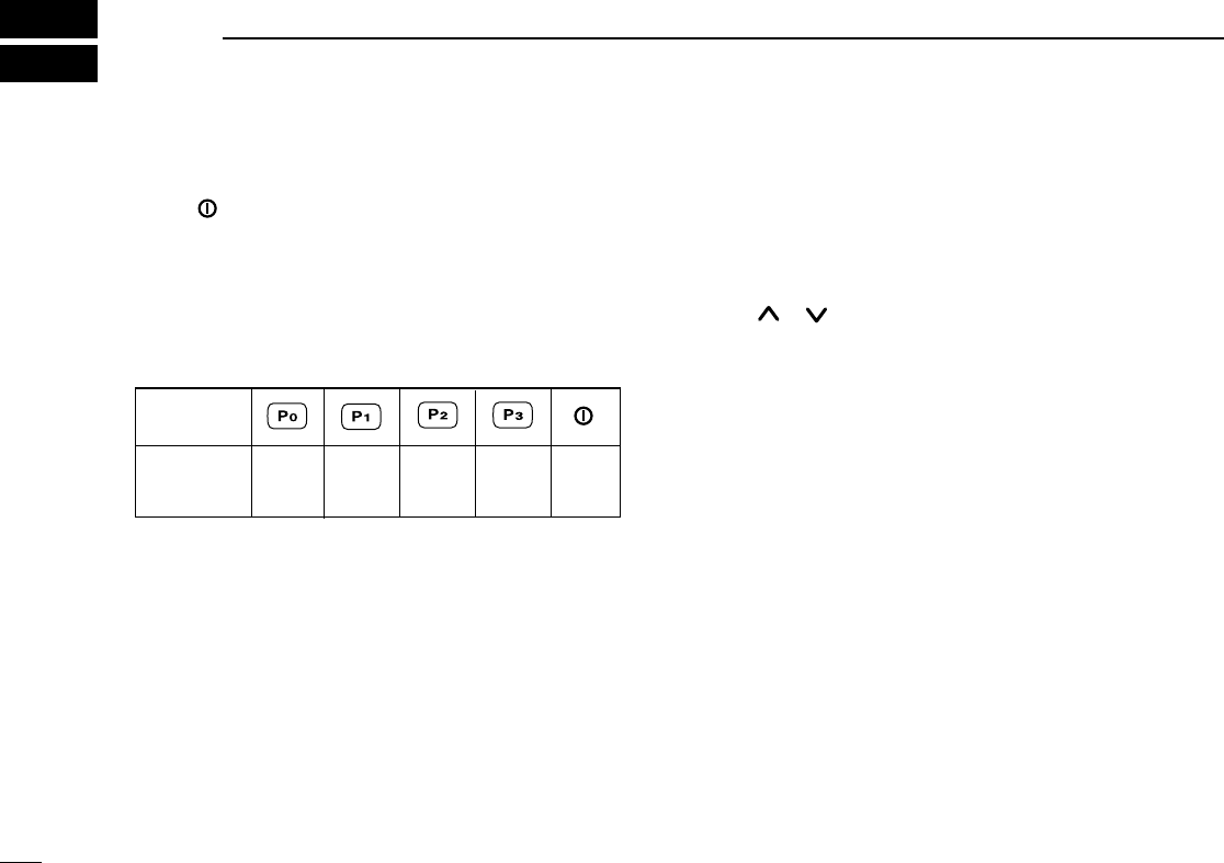
■Turning power ON
qPush [ ] to turn the power ON.
wIf the transceiver is programmed for a start up passcode,
input the digit codes as directed by your dealer.
• The keys in the table below can be used for password input:
• The transceiver detects numbers in the same block as identical.
Therefore “01234” and “56789” are same.
eWhen the “PASSWORD” indication does not clear after
inputting 4 digits, the input code number is incorrect. In this
case, turn the power off and start over.
■Channel selection
Several types of channel selection are available. The meth-
ods may differ according to your system setup.
NON-BANK TYPE:
Push []/[]to select the desired operating channel in
sequence; or, push one of the [CH 1] to [CH 4] keys to select
a channel directly.
BANK-TYPE:
Push [BANK] to select the desired bank number or name.
AUTOMATIC SCAN TYPE:
Channel setting is not necessary for this type. When turning
the power ON, the transceiver automatically starts scanning.
Scanning stops when receiving a call or when taking the
microphone off hook.
KEY
NUMBER 01234
56789
!IC-F111_F121_F211_F221.qxd 03.2.12 10:02 AM Page 7 (1,1)

8
2
OPERATION
■Receiving and transmitting
RECEIVING:
qPush [ ] to turn the power ON.
wPush []and []to select a channel.
eWhen receiving a call, adjust the audio output level to a
comfortable listening level.
TRANSMITTING:
rTake the microphone off hook.
• 2-tone, 5-tone mute may be released. (The ‘audible’ condition is
selected and “ ” appears.)
• A priority channel may be selected automatically.
tWait for the channel to become clear.
• The channel is busy when “ ” appears.
yPush the [CALL] key when initiating a call from your side.
• Coded audio may be heard from the transceiver, then “ ”
appears.
• This operation may not be necessary depending on your signal-
ing system. Contact your dealer.
uWhile pushing and holding [PTT], speak into the micro-
phone at your normal voice level.
iRelease [PTT] to receive.
IMPORTANT!: To maximize the readability of your signal;
➥Pause briefly after pushing [PTT].
➥Hold the microphone 2 to 5 cm from your mouth, then
speak into the microphone at a normal voice level.
DTransmitting notes
• Transmit inhibit function
The transceiver has several inhibit functions which restrict
transmission under the following conditions:
- The channel is in mute condition (‘Inaudible’ condition; “ ” does
not appear).
- Channel is busy.
- A matched/un-matched CTCSS code is received.
- The selected channel is a ‘receive only’ channel.
• Time-out timer
After continuous transmission for a pre-programmed period,
the time-out timer is activated causing the transceiver to stop
transmitting and automatically select receive.
• Penalty timer
Once the time-out timer is activated, transmission is further
inhibited for a period determined by the penalty timer.
!IC-F111_F121_F211_F221.qxd 03.2.12 10:02 AM Page 8 (1,1)

9
2OPERATION
DTX code channel selection
If the transceiver has a [TX CH] key, the display can be tog-
gled between the operating channel number (or name) and
TX code channel number (or name). When the TX code
channel number (or name) is displayed, the []/[]keys
select the TX code channel.
To select a TX channel:
qPush [TX CH]—a TX code channel appears.
wPush []/[]to select the desired TX code channel.
ePush [CALL] to transmit the selected TX code.
rPush [TX CH] again to return to the channel display.
DTX code number selection
If the transceiver has a [TX CH] key, TX code contents can be
changed within the allowable digits.
To select a TX code:
qPush [TX CH]—a TX code number appears and the first
digit blinks.
wPush []/[]to select the desired number of the blink-
ing digit.
ePush [TX CH] to enter the selected number and the next
digit will start blinking automatically.
rRepeat step wand eto input all allowed digits.
tPush [CALL] to transmit the selected TX code.
DDTMF transmission
If the transceiver has a [DTMF] key, the automatic DTMF
transmission function is available. Up to 7 DTMF channels
may be available.
To transmit a DTMF code:
qPush [DTMF]—a DTMF code channel appears.
wPush []/[]to select the desired DTMF channel.
ePush and hold [DTMF] to transmit the DTMF code on the
selected DTMF channel.
DScrambler function
The UT-109 (#02) or UT-110 (#02) optional voice scrambler
unit provides high performance private communication
between stations with the same scrambler codes.
To turn the scrambler function ON and OFF:
qPush and hold [SCRM] to turn the scrambler function ON.
wPush [SCRM] to turn the function OFF.
!IC-F111_F121_F211_F221.qxd 03.2.12 10:02 AM Page 9 (1,1)

10
2
OPERATION
DUser set mode
User set mode is accessed at power ON and allows you to
set seldom-changed settings. In this case you can “cus-
tomize” transceiver operation to suit your preferences and
operating style.
Entering the user set mode:
qWhile pushing and holding []and [], push [POWER]
to enter user set mode ON, allowing you to set seldom-
changed settings.
wPush and hold [P0] to select the appropriate item. Then,
push []or []to set the desired level/mode.
- Available set mode functions;
• Backlight : OFF, Dim, Auto or ON
• Beep : OFF or ON
• SQL Level : 0 to 255
• AF Min level : 0 to 255
ePush [POWER] (or push and hold [P0]) again to exit set
mode.
User set mode is also available via a programmable key.
Please refer to p. 6 [SET] section.
!IC-F111_F121_F211_F221.qxd 03.2.12 10:02 AM Page 10 (1,1)

11
3OPTIONAL SmarTrunk II™OPERATION
■SmarTrunk II™and
conventional modes
This transceiver is capable of SmarTrunk II™ functions.
The optional UT-105 allows communication in conventional
channels or SmarTrunk II™ channels. Select a channel bank
for SmarTrunk II™ before trunking operation.
• Push [BANK]several times to select a channel bank for con-
ventional channels or SmarTrunk II™ channels.
- Scanning starts when a channel bank for SmarTrunk II™ opera-
tion is selected.
- Contact your dealer for channel bank details.
NOTE: Optional HM-100TN DTMF MICROPHONE is
required. Contact your dealer for details.
■SmarTrunk II™operation
These features are enabled by a dealer and may not be avail-
able in your system. Contact your dealer for details.
DPlacing a telephone call
Enter the phone number followed by [1], [M].
• A high-pitched beep indicates that the number is accepted.
• When the called party answers, push the [PTT] switch to talk, and
release it to listen.
DCalling another local system subscriber
Enter the subscriber number followed by [3], [M].
• A high-pitched beep indicates that the number is accepted.
• You hear ringing, then two short beeps when the subscriber
answers.
• If the other subscriber is on another call or out of range, you hear a
fast busy signal and the call terminates automatically.
DReceiving a call
When you hear ringing, push [M] to answer.
• For a group call, you hear a short ring followed by two short beeps.
You do not have to answer a group call to hear it over the air.
!IC-F111_F121_F211_F221.qxd 03.2.12 10:02 AM Page 11 (1,1)

12
3
OPTIONAL SmarTrunk II™ OPERATION
DTerminating a call
After completing a call, push [#] to disconnect (hang up).
IMPORTANT!: If one person in the conversation termi-
nates a call, all participants will be cut off.
DLast number re-dial
Push [M] 2 times to automatically re-dial the last called num-
ber.
• A high-pitched beep indicates that the number is accepted.
DMemory speed-dialling
To automatically dial a commonly used number from memory:
• Push [M] followed by the memory location (0–9).
DTurbo SpeeDial
To automatically dial a commonly used number with one
push:
• Push one of the turbo SpeeDial keys ([A], [B], [C] or [D]).
DProgramming memory speed dial
qPush and hold [M] until you hear a high-pitched beep.
wEnter the memory location (0–9, A, B, C, D), the telephone
or subscriber number, then [1], [M] (or [3], [M] if for another
system subscriber).
• A high-pitched beep indicates successful programming.
• Memories [A]–[D] are used for the Turbo SpeeDial.
DSystem busy indication
If all channels are busy, three low beeps sound after you initi-
ate a call. Try the call again later.
DPTT dispatch operation
qPush [PTT] once (without dialling) to initiate a dispatch call.
wBegin talking after you hear three beeps (one short, high-
pitched, two very-short, low-pitched).
eReceiving a dispatch call is indicated by the same three-
beep sequence.
• It is not necessary to push [M] to answer a dispatch call.
DEmergency call
Push [0], [M] to initiate an emergency call.
• Contact your dealer for details.
DClear channel alerting
If all channels are busy, the transceiver automatically begins
searching for an open channel and beeps every ten seconds.
When two short beeps (low-pitched, then high-pitched) are
heard, a channel is available. Push [M] two times immediate-
ly to re-dial the last number.
NOTE: For additional operating instructions, contact your
dealer.
!IC-F111_F121_F211_F221.qxd 03.2.12 10:02 AM Page 12 (1,1)
13
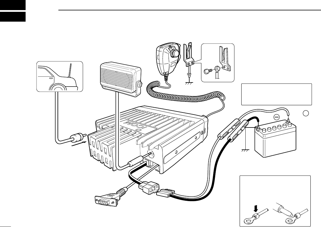
4CONNECTION AND MAINTENANCE
Optional cable
(OPC-617)
Antenna
NEVER connect to
a 24 V battery.
+
red:
black:
12V
Battery
Solder
Crimp
NOTE: Use the terminals as
shown below for the cable
connections.
R CAUTION! NEVER re-
move the fuse-holder from
the DC power cable.
e
r
t
w
To the antenna
connector
q
Optional speaker
(SP-22)
■Rear panel and connection
!IC-F111_F121_F211_F221.qxd 03.2.12 10:02 AM Page 13 (1,1)
14
4
CONNECTION AND MAINTENANCE
qANTENNA CONNECTOR
Connects to an antenna. Contact your dealer about an-
tenna selection and placement.
wMICROPHONE HANGER
Connect the supplied microphone hanger to the vehicle’s
ground for microphone on/off hook functions. (See p. 2)
eDC POWER RECEPTACLE
Connects to a 12 V DC battery. Pay attention to polarities.
NEVER connect to a 24 V battery. This could damage the
transceiver.
rOPTIONAL CABLE (OPC-617)
Connect an external modem unit, dimmer control, etc.
tEXTERNAL SPEAKER JACK
Connect a 4–8 Ωexternal speaker, if desired.
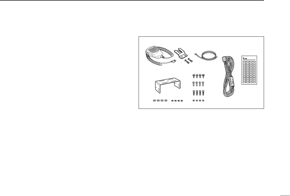
■Supplied Accessories
qMicrophone ...................... 1
wMicrophone hanger and
screw set ..................... 1 set
eMicrophone hanger cable . 1
rDC power cable (OPC-1132)
............................................1
tFunction name stickers*
(KEY STICKER) ....................1
yMounting bracket .............. 1
uBracket bolts ..................... 4
iMounting screws (M5×12) . 4
oSelf-tapping screws (M5×20)
........................................... 4
!0 Flat washers ...................... 4
!1 Spring washers ................. 4
!2 Nuts ................................... 4
*Function name stickers
There are no names on the programmable function keys since the
functions can be freely assigned to these keys.
Attach the supplied function name stickers above the appropriate
keys for easy recognition of that key’s assigned function.
qw e
r
yu
i
o
!0 !1 !2
t
KEY-STICKER
ICOM
!IC-F111_F121_F211_F221.qxd 03.2.12 10:02 AM Page 14 (1,1)
15
4CONNECTION AND MAINTENANCE
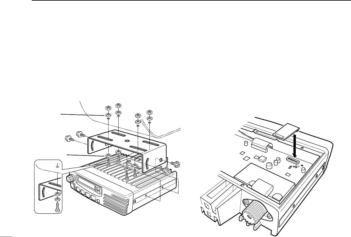
■Mounting the transceiver
The universal mounting bracket supplied with your transceiv-
er allows overhead mounting.
•Mount the transceiver securely with the 4 supplied screws
to a thick surface which can support more than 1.5 kg.
Flat washer
Spring washer
When using
self-tapping screws
■Optional UT-105, UT-108 or
UT-111 installation
Install the optional UT-105, UT-108 or UT-111 unit as follows:
qTurn the power OFF, then disconnect the DC power cable.
wUnscrew the 4 cover screws, then remove the bottom
cover.
eInstall the unit as shown in the diagram below.
rReplace the bottom cover and screws, then re-connect the
DC power cable.
UT-105/
UT-108/
UT-111
Front panel
!IC-F111_F121_F211_F221.qxd 03.2.12 10:02 AM Page 15 (1,1)
16
4
CONNECTION AND MAINTENANCE
■Optional UT-109 or UT-110
installation
qTurn the power OFF, then disconnect the DC power cable.
wUnscrew the 4 cover screws, then remove the bottom
cover.
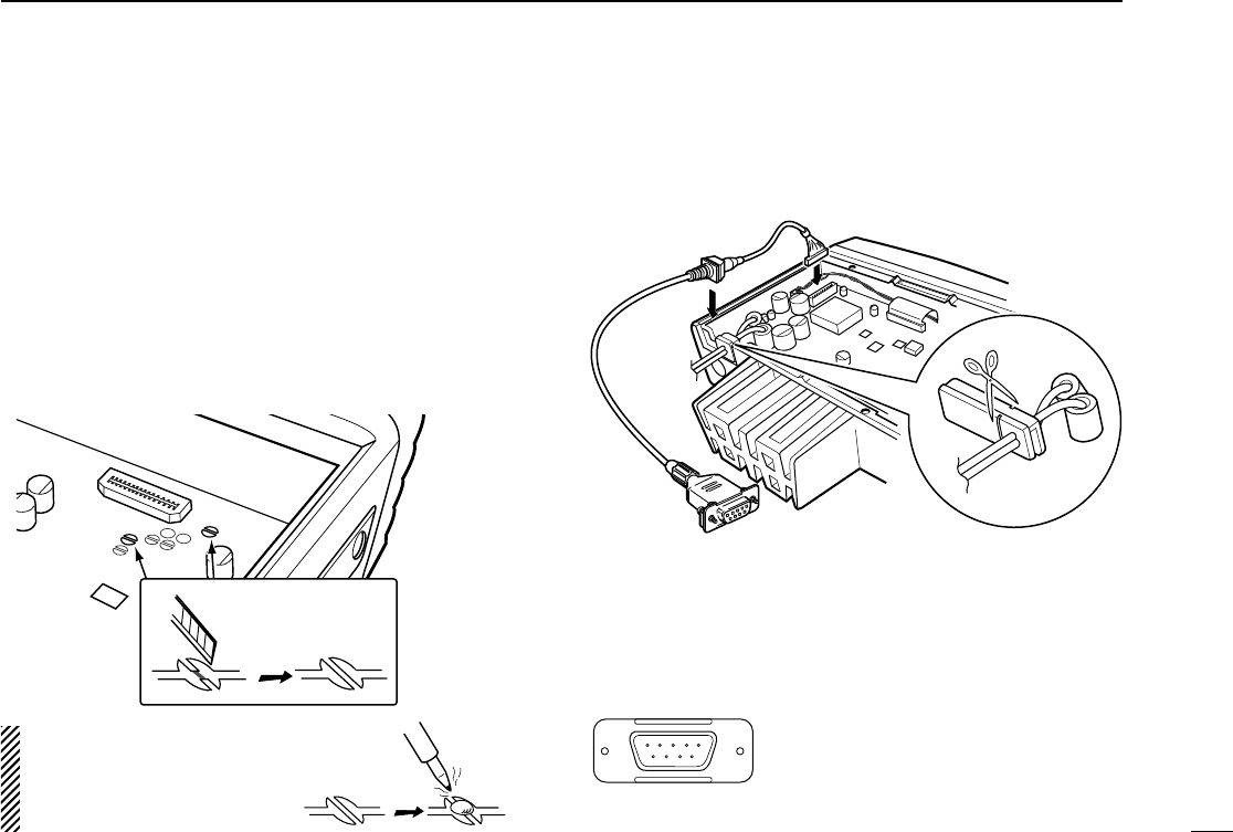
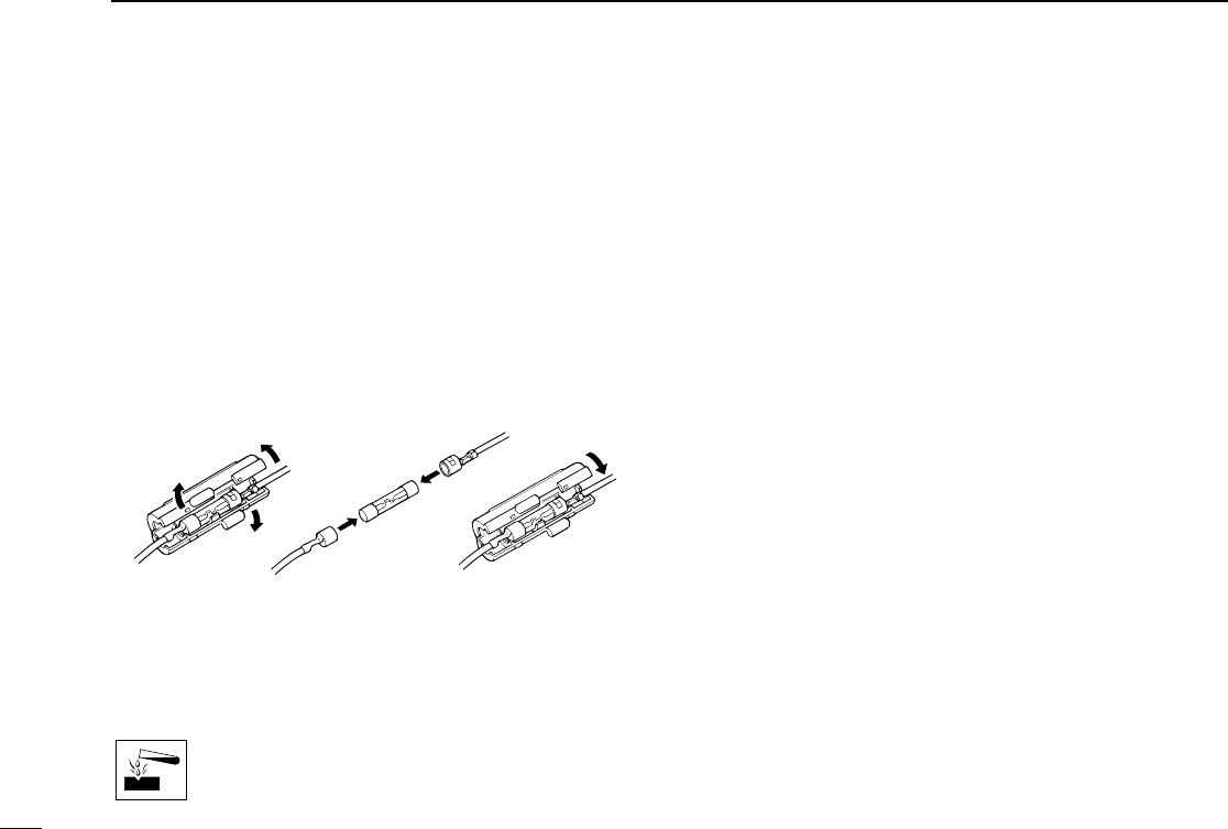
eCut the pattern on the PCB at the TX mic circuit (MIC) and
RX AF circuit (DISC) as shown below.
rInstall the scrambler unit as described in the installation of
optional UT-105, UT-108 or UT-111 as on the page at left.
tReplace the bottom cover and screws.
NOTE: Be sure to re-solder the
above disconnected points
when you remove the scrambler
units. Otherwise no TX modula-
tion or AF output is available.
MIC
DISC
Front panel
q
Dimmer cont. IN or
IGSW cont. IN
wAF OUT
eDet. AF OUT
rMod. IN
tPTT control IN or
yHorn drive cont. OUT
uAF GND
iDet. AF GND
oMod. GND
OPTIONAL CABLE PIN ASSIGNMENT
t r e w q
o i u yFTSW control IN
OPC-617
Cut off the bushing as in the illustra-
tion, when you install the optional
OPC-617.
■Optional OPC-617 installation
Install the OPC-617 as shown below.
!IC-F111_F121_F211_F221.qxd 03.2.12 10:02 AM Page 16 (1,1)
17
4CONNECTION AND MAINTENANCE
■Antenna
A key element in the performance of any communication sys-
tem is an antenna. Contact your dealer about antennas and
the best places to mount them.
■Fuse replacement
A fuse is installed in the supplied DC power cable. If a fuse
blows or the transceiver stops functioning, track down the
source of the problem if possible, and replace the damaged
fuse with a new rated one.
❑Fuse rating: 20 A
■Cleaning
If the transceiver becomes dusty or dirty, wipe it clean with a
soft, dry cloth.
AVOID the use of solvents such as benzene or
alcohol, as they may damage the transceiver sur-
faces.
!IC-F111_F121_F211_F221.qxd 03.2.12 10:02 AM Page 17 (1,1)

18
5
OPTIONS
SP-22 EXTERNAL SPEAKER
Compact and easy-to-install.
Input impedance : 4 Ω
Max. input power : 5 W
HM-100TN
DTMF microphone.
SM-25
Desktop microphone.
UT-105 SmarTrunk IITM Logic Board
Provides SmarTrunk IITM capabilities.
UT-108 DTMF DECODER UNIT
Provides pager and code squelch capabilities.
UT-109/UT-110 (#02) VOICE SCRAMBLER UNIT
• UT-109 : Non-rolling type (max. 32 codes)
• UT-110 : Rolling type (max. 1020 codes)
UT-111 TRUNKING BOARD
Provides trunking operation.
OPC-617 ACC CABLE
Allows you to connect to an external terminal.
!IC-F111_F121_F211_F221.qxd 03.2.12 10:02 AM Page 18 (1,1)
19
6SAFETY TRAINING INFORMATION
Your Icom radio generates RF electromagnetic
energy during transmit mode. This radio is
designed for and classified as “Occupational
Use Only”, meaning it must be used only during
the course of employment by individuals aware
of the hazards, and the ways to minimize such
hazards. This radio is NOT intended for use by the “General
Population” in an uncontrolled environment.
• For compliance with FCC and Industry Canada RF Exposure
Requirements, the transmitter antenna installation shall comply with
the following two conditions:
1. The transmitter antenna gain shall not exceed 0 dBi.
2. IC-F121:
The antenna is required to be located outside of a vehicle and
kept at a distance of 1 meter or more between the transmitting
antenna of this device and any persons during operation. For
small vehicle as worst case, the antenna shall be located on the
roof top at any place on the centre line along the vehicle in order
to achieve 1 meter separation distance. In order to ensure this
distance is met, the installation of the antenna must be mounted
at least 1 meter away from the nearest edge of the vehicle in
order to protect against exposure to bystanders.
3. IC-F221:
The antenna is required to be located outside of a vehicle and
kept at a distance of 79 centimeters or more between the trans-
mitting antenna of this device and any persons during operation.
For small vehicle as worst case, the antenna shall be located on
the roof top at any place on the centre line along the vehicle in
order to achieve 79 centimeters separation distance. In order to
ensure this distance is met, the installation of the antenna must
be mounted at least 79 centimeters away from the nearest edge
of the vehicle in order to protect against exposure to bystanders.
To ensure that your exposure to RF electromag-
netic energy is within the FCC allowable limits
for occupational use, always adhere to the fol-
lowing guidelines:
•DO NOT operate the radio without a proper antenna attached, as
this may damage the radio and may also cause you to exceed FCC
RF exposure limits. A proper antenna is the antenna supplied with
this radio by the manufacturer or an antenna specifically authorized
by the manufacturer for use with this radio.
•DO NOT transmit for more than 50% of total radio use time (
“
50%
duty cycle”). Transmitting more than 50% of the time can cause FCC
RF exposure compliance requirements to be exceeded. The radio
is transmitting when the “TX indicator” lights red. You can cause the
radio to transmit by pressing the “PTT” switch.
Electromagnetic Interference/Compatibility
During transmissions, your Icom radio generates RF energy that can
possibly cause interference with other devices or systems. To avoid
such interference, turn off the radio in areas where signs are posted
to do so. DO NOT operate the transmitter in areas that are sensitive
to electromagnetic radiation such as hospitals, aircraft, and blasting
sites.
WARNING
CAUTION
!IC-F111_F121_F211_F221.qxd 03.2.12 10:02 AM Page 19 (1,1)

MEMO
!IC-F111_F121_F211_F221.qxd 03.2.12 10:02 AM Page 20 (1,1)

1-1-32 Kamiminami, Hirano-ku, Osaka 547-0003 Japan
A-6235H-1EX
Printed in Japan
© 2003 Icom Inc.
!IC-F111_F121_F211_F221.qxd 03.2.12 10:02 AM Page Z (1,1)