ICOM orporated 268201 UHF-FM Face Held Transceiver User Manual IC F50 F60 BIIS
ICOM Incorporated UHF-FM Face Held Transceiver IC F50 F60 BIIS
UserManual.wiki
>
ICOM orporated
>
268201 User Manual
Manual
Navigation menu
Upload a User Manual
Namespaces
Wiki Guide
HTML
PDF
Info
Views
User Manual
Discussion / Help
Navigation
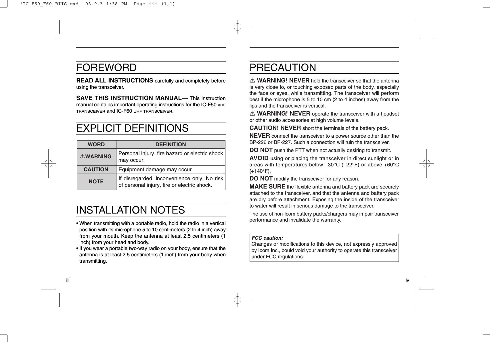
![viTABLE OF CONTENTSvSAFETY TRAINING INFORMATION …………………………………… iFOREWORD ……………………………………………………………… iiiEXPLICIT DEFINITIONS ………………………………………………… iiiINSTALLATION NOTES ………………………………………………… iiiPRECAUTION …………………………………………………………… ivTABLE OF CONTENTS ………………………………………………… vSUPPLIED ACCESSORIES …………………………………………… vi1 ACCESSORIES ……………………………………………………… 1–2‘Accessory attachments……………………………………………… 12 PANEL DESCRIPTION …………………………………………… 3–11‘Front, top and side panels ………………………………………… 3‘Function display ……………………………………………………… 6‘Programmable function keys ……………………………………… 73 CONVENTIONAL OPERATION ………………………………… 12–18‘Turning power ON ………………………………………………… 12‘Channel selection ………………………………………………… 12‘Call procedure ……………………………………………………… 13‘ Receiving and transmitting ……………………………………… 14‘ Scrambler function ………………………………………………… 17‘ User set mode ……………………………………………………… 184 BIIS OPERATION ………………………………………………… 19–34‘Default setting ……………………………………………………… 19‘Receiving a call …………………………………………………… 20‘Transmitting a call ………………………………………………… 23‘Receiving a message ……………………………………………… 26‘Transmitting a status ……………………………………………… 29‘Transmitting an SDM ……………………………………………… 30‘Position data transmission ………………………………………… 31‘Printer connection ………………………………………………… 32‘PC connection ……………………………………………………… 32‘Digital ANI …………………………………………………………… 32‘Auto emergency transmission …………………………………… 33‘Stun function………………………………………………………… 33‘BIIS indication ……………………………………………………… 34‘Priority A channel selection ……………………………………… 345 BATTERY CHARGING ………………………………………… 35–44‘Battery charging …………………………………………………… 35‘Cautions …………………………………………………………… 36‘Optional battery chargers ………………………………………… 37‘Optional battery case ……………………………………………… 436 SPEAKER-MICROPHONE ……………………………………… 45–46‘Optional HM-138 description ……………………………………… 45‘Attachment ………………………………………………………… 467 OPTIONS ………………………………………………………… 47–48SUPPLIED ACCESSORIESThe following accessories are supplied: Qty.• Flexible antenna . . . . . . . . . . . . . . . . . . . . . . . . . . . . . . . . . . . . .1• Battery pack . . . . . . . . . . . . . . . . . . . . . . . . . . . . . . . . . . . . . . . .1• Jack cover . . . . . . . . . . . . . . . . . . . . . . . . . . . . . . . . . . . . . . .1 set• Belt clip . . . . . . . . . . . . . . . . . . . . . . . . . . . . . . . . . . . . . . . . .1 set• Function name stickers* (KEY-STICKER) . . . . . . . . . . . . . . . . . .1*There are no names on the programmable function keys since thefunctions can be freely assigned to [P0] to [P3], [Red], [ ] and [ ] keys.Attach the supplied function name stickers above the appropriatekeys for easy recognition of that key’s assigned function.!IC-F50_F60 BIIS.qxd 03.9.3 1:38 PM Page v (1,1)](https://usermanual.wiki/ICOM-orporated/268201/User-Guide-380942-Page-4.png)
![21ACCESSORIES111ACCESSORIES■Accessory attachmentsDFlexible antennaConnect the supplied flexible antennato the antenna connector.CAUTION!• NEVER HOLD by the antennawhen carrying the transceiver.• Transmitting without an antennamay damage the transceiver.ïBattery packTo attach the battery pack:Slide the battery pack on the back of the transceiver in the direc-tion of the arrow (q), then lock it with the battery release button.*Slide the battery pack until the battery release button makes a‘click’ sound.To release the battery pack:Push the battery release button in the direction of the arrow (w) asshown below. The battery pack is then released.qwBattery packBattery release buttonïJack coverAttach the jack cover when the optional speaker-microphone is notused.DBelt clipAttach the belt clip to the back of the transceiver with the suppliedscrews.Supplied screwsqwerTo attach the jack cover:qInsert the jack cover into the[SP MIC] connector.wTighten the screw.To detach the jack cover:eUnscrew the screw with aphillips screwdriver.rDetach the jack cover for thespeaker-microphone connec-tion.!IC-F50_F60 BIIS.qxd 03.9.3 1:38 PM Page 1 (1,1)](https://usermanual.wiki/ICOM-orporated/268201/User-Guide-380942-Page-5.png)
![42PANEL DESCRIPTION232PANEL DESCRIPTION■Front, top and side panelsNOTE: If the speaker netting (for dust proof) becomes wet,dry it with a hair drier (cool mode), etc. before operating thetransceiver. Otherwise the audio may be difficult to hear forloss of the sound pressure.qwertyiuMicrophoneFunction display(p. 6)Speaker(See the followning NOTE.)qVOLUME CONTROL [VOL]Turns power ON and adjusts the audio level.wRED BUTTONDesired function can be assigned by your dealer.eANTENNA CONNECTORConnects the supplied antenna.rSPEAKER-MICROPHONE CONNECTOR [SP MIC]Connects the optional speaker-microphone. (p. 46)tDEALER-PROGRAMMABLE KEYS [P0] to [P3]Desired functions can be assigned independently by your dealer.yCH DOWN AND UP KEYS [ ]/[ ]➥During standby condition, push to select an operating channel.➥After pushing [TX Code CH Select], push to select a TX codechannel.➥After pushing [DTMF Autodial], push to select a DTMF channel.➥After pushing and holding [Scan A Start/Stop]/[Scan BStart/Stop], push to select a scan group.➥After pushing [Digital], push to select a BIIS code, status num-ber or SDM.*Desired functions can be assigned independently by your dealer.☞Continue to the next page.[SP MIC] jack coverNOTE: KEEP the [SP MIC] jack cover attached to the transceiver when the speaker-microphone is not used. (See p. 2 for details)!IC-F50_F60 BIIS.qxd 03.9.3 1:38 PM Page 3 (1,1)](https://usermanual.wiki/ICOM-orporated/268201/User-Guide-380942-Page-6.png)
![62PANEL DESCRIPTION252PANEL DESCRIPTION■Front, top and side panels (Continued)uTRANSMIT/BUSY INDICATORLights red while transmitting; lights green while receiving a sig-nal, or when the squelch is open.iPTT SWITCH [PTT]➥Push and hold to transmit; release to receive.■Function displayqOUTPUT POWER INDICATORAppears when Low 2 or Low 1 is selected.wAUDIBLE INDICATOR➥Appears when the channel is in the ‘audible’(unmute) condi-tion.➥Appears when the specified 2/5-tone/BIIS code is received.eCOMPANDER INDICATOR Appears when the compander function is activated.rKEY LOCK INDICATOR Appears during the key lock function ON.tSCRAMBLER INDICATORAppears when the voice scrambler function is activated.yBELL INDICATORAppears/blinks when the specific 2/5-tone/BIIS code is received,according to the programming.uBATTERY INDICATORAppears or blinks when the battery decreases to a specifiedlevel.iALPHANUMERIC DISPLAYDisplays the operating channel number, channel names, Setmode contents, DTMF numbers, etc.ruyitewq!IC-F50_F60 BIIS.qxd 03.9.3 1:38 PM Page 5 (1,1)](https://usermanual.wiki/ICOM-orporated/268201/User-Guide-380942-Page-7.png)
![72PANEL DESCRIPTION82PANEL DESCRIPTION2■Programmable function keysThe following functions can be assigned to [P0], [P1], [P2], [P3],[Red], []and []programmable function keys. Consult your Icom dealer or system operator for details concerningyour transceivers programming.If the following explanations, programmable function names arebracketed, the specific switch used to activate the function dependson programming.CH UP AND DOWN KEYS• Select an operating channel.• Select a transmit code channel after pushing the [TX Code CHSelect] keys.• Select a DTMF channel after pushing the [DTMF Autodial] key.• Select a scan group after pushing and holding the [Scan AStart/Stop]/[Scan B Start/Stop] keys.• Select a BIIS code, status number or SDM after pushing the [Digital] keys.BANK SELECT KEYPush this key, then push [CH Up] or [CH Down] to select the de-sired bank.SCAN START/STOP KEYS➥Push this key to start scanning; and push again to stop.➥Push and hold this key to indicate the scan group, then selectthe desired scan group using [CH Up]/[CH Down].SCAN TAG KEYAdds or deletes the selected channel to the scan group.PRIORITY CHANNEL KEYS➥Push to select Priority A or Priority B channel.➥Push and hold [Prio A (Rewrite)] to rewrite the Prio A channel.MR-CH 1/2/3/4 KEYSSelect an operating channel directly.MONITOR KEY➥Mute and release the CTCSS (DTCS) or 2-tone squelch mute.Open any squelches/deactivate any mutes while pushing thiskey. (LMR operation only)➥Activates one of (or two of) the following functions on each chan-nel independently: (PMR or BIIS PMR operation only)• Push and hold to un-mute the channel (audio is emitted; ‘Audible’condition).• Push to mute the channel (sets to ‘Inaudible’only).• Push to un-mute the channel (sets to ‘Audible’only).• Push after the communication is finished to send a ‘reset code’.NOTE: The un-mute condition (‘Audible’condition) may auto-matically return to the mute condition (‘Inaudible‘ condition)after a specified period.LOCK KEYPush and hold to electronically locks all programmable keys exceptthe following:[Call] (incl. Call A and Call B), [Moni(Audi)] and [Emergency] keys.OUTPUT POWER SELECTION KEYSelect the transmit output power temporarily or permanently, de-pending on the pre-setting.•Ask your dealer for the output power level for each selection.!IC-F50_F60 BIIS.qxd 03.9.3 1:38 PM Page 7 (1,1)](https://usermanual.wiki/ICOM-orporated/268201/User-Guide-380942-Page-8.png)
![102PANEL DESCRIPTION292PANEL DESCRIPTIONC.TONE CHANNEL ENTER KEYSelect the continuous tone channel using [CH Up]/[CH Down] keysto change the tone frequency/code setting after pushing this key forpermanently operation.TALK AROUND KEYTurn the talk around function ON and OFF.•The talk around function equalizes the transmit frequency to the re-ceive frequency for mobile-to-mobile communication.WIDE/NARROW KEYPush to toggle the IF bandwidth between wide and narrow.• The wide passband width can be selected from 25.0 or 20.0 kHz usingthe CS-F50 CLONING SOFTWARE. (PMR or BIIS PMR operation only)Ask your dealer for details.DTMF AUTODIAL KEY➥Push to enter the DTMF channel selection mode. Then selectthe desired DTMF channel using [CH Up]/[CH Down] keys.➥After selecting the desired DTMF channel, push this key to trans-mit the DTMF code.DTMF RE-DIAL KEYPush to transmit the last-transmitted DTMF code.CALL KEYSPush to transmit a 2/5-tone/BIIS ID code.•Call transmission is necessary before you call another station de-pending on your signalling system.•The [Call A] and/or [Call B] keys may be available when your systememploys selective ‘Individual/Group’calls. Ask your dealer which call isassigned to each key.EMERGENCY KEYS➥Push and hold to transmit an emergency call.➥When [Emergency Single (Silent)] or [Emergency Repeat(Silent)] is pushed, an emergency call is transmitted without abeep emission and LCD indication change.• If you want to cancel the emergency call, push (or push and hold)the key again before transmitting the call.• The emergency call is transmitted one time only or repeatedly untilreceiving a control code depending on the pre-setting.TX CODE ENTER KEY (PMR or BIIS PMR operation only)Push to enter the direct ID code edit mode, for both 5-tone andMSK. Then set the desired digit using [CH Up]/[CH Down]/[TX Code CH Up]/[TX Code CH Down]. (p. 16)TX CODE CHANNEL SELECT KEY➥Push to enter the direct ID code channel selection mode. Thenset the desired channel using [CH Up]/[CH Down]/[TX Code CHUp]/[TX Code CH Down]. (p. 15)➥During in ID code channel selection mode, push for 1 sec. toenter the ID code edit mode for 5-tone and MSK. Then set thedesired digit using [CH Up]/[CH Down]/[TX Code CH Up]/[TXCode CH Down]. (p. 16)TX CODE CHANNEL UP/DOWN KEYSPush to select a TX code channel directly.ID MEMORY READ KEY (PMR or BIIS PMR operation only)➥Recalls detected ID codes.•Push this key, then push [CH Up]/[CH Down] for selection.•Up to 5 ID’s are memorized.➥Push and hold to erase the selected memorized ID’s.!IC-F50_F60 BIIS.qxd 03.9.3 1:38 PM Page 9 (1,1)](https://usermanual.wiki/ICOM-orporated/268201/User-Guide-380942-Page-9.png)
![123CONVENTIONAL OPERATION23112PANEL DESCRIPTIONVOICE SCRAMBLER FUNCTIONPush to toggle the voice scrambler function ON and OFF.COMPANDER KEYPush to toggle the compander function ON and OFF. The compander function reduces noise components from the trans-mitting audio to provide clear communication.USER SET MODE KEY➥Push and hold to enter user set mode.• During user set mode, push this key to select an item, and push[CH Up]/[CH Down] to change the value or condition.➥Push and hold this key again to exit user set mode.•User set mode is also available via the ‘Power ON function’. Pleaserefer to p. 18 also.DIGITAL KEY (BIIS operation only)➥Push to select the call ID list, transmit message and standbycondition. Toggles between queue channel and received mes-sage record indication after queue channel is selected.➥Push and hold to select queue channel indication.STATUS UP/DOWN KEYS (BIIS operation only)➥During the standby condition, push to display the transmit statusindication and select a status number.➥When a received SDM is displayed, push to cancel the automaticscroll and scroll the message manually.➥When an SDM that contains more than 8 characters is displayed,push to scroll the message manually.■Turning power ONqRotate [VOL] to turn power ON.wIf the transceiver is programmed for a start up passcode, inputdigit codes as directed by your dealer.• The keys in the table below can be used for password input:• The transceiver detects numbers in the same block as identical.Therefore “01234” and “56789” are the same.eWhen the “PASSWORD” indication does not clear after inputting4 digits, the input code number may be incorrect. Turn power offand start over in this case.■Channel selectionSeveral types of channel selections are available. Methods may dif-fer according to your system set up.NON-BANK TYPE:Push [ ]/[ ] to select the desired operating channel, in se-quence; or, push one of the [MR-CH 1] to [MR-CH 4] to select achannel directly.BANK-TYPE:Push [Bank], then push [ ] or [ ] to select the desired bank.AUTOMATIC SCAN TYPE:Channel setting is not necessary for this type. When turning thepower ON, the transceiver automatically starts scanning. Scanningstops when receiving a call.KEYNUMBER 0549382716!IC-F50_F60 BIIS.qxd 03.9.3 1:38 PM Page 11 (1,1)](https://usermanual.wiki/ICOM-orporated/268201/User-Guide-380942-Page-10.png)
![143CONVENTIONAL OPERATION3133CONVENTIONAL OPERATION■Call procedureWhen your system employs tone signalling (excluding CTCSS andDTCS), the call procedure may be necessary prior to voice trans-mission. The tone signalling employed may be a selective callingsystem which allows you to call specific station(s) only and preventunwanted stations from contacting you.qSelect the desired TX code channel or 2/5-tone code accordingto your System Operator’s instructions.• This may not be necessary depending on programming.• Refer to pgs. 15, 16 for selection.wPush the call switch (assigned to one of the dealer programma-ble switches: [P0], [P1], [P2], [P3], [Red], [ ] and []).eAfter transmitting a 2/5-tone code, the remainder of your com-munication can be carried out in the normal fashion.Selective calling Non-selective calling■Receiving and transmittingNOTE: Transmitting without an antenna may damage the trans-ceiver. See p. 1 for antenna attachment.Receiving:qRotate [VOL] to turn power ON.wPush [ ] or [ ] to select a channel.eWhen receiving a call, adjust the audio output level to a comfort-able listening level.Transmitting:Wait for the channel to become clear to avoid interference.qWhile pushing and holding [PTT], speak into the microphone at anormal voice level.• When a tone signalling system is used, the call procedure de-scribed at left may be necessary.wRelease [PTT] to return to receive.IMPORTANT: To maximize the readability of your signal;1. Pause briefly after pushing [PTT].2. Hold the microphone 5 to 10 cm (2 to 4 inches) from yourmouth, then speak into the microphone at a normal voicelevel.!IC-F50_F60 BIIS.qxd 03.9.3 1:38 PM Page 13 (1,1)](https://usermanual.wiki/ICOM-orporated/268201/User-Guide-380942-Page-11.png)
![163CONVENTIONAL OPERATION3153CONVENTIONAL OPERATIONDTransmitting notes• Transmit inhibit functionThe transceiver has several inhibit functions which restrict trans-mission under the following conditions:- The channel is in mute condition (‘Inaudible’condition; “”does not appear).- Channel is busy.- Un-matched (or matched) CTCSS is received.- The selected channel is a ‘receive only’channel.• Time-out timerAfter continuous transmission for the pre-programmed time period,the time-out timer is activated, causing the transceiver to stop trans-mitting.• Penalty timerOnce the time-out timer is activated, transmission is further inhibitedfor a period determined by the penalty timer.DTX code channel selectionIf the transceiver has [TX Code CH Select], indication can be tog-gled between the operating channel number (or name) and TXcode channel number (or name). When the TX code channel num-ber (or name) is displayed, the [ ]/[ ] key selects the TX codechannel.TO SELECT A TX CHANNEL:qPush [TX Code CH Select]— a TX code channel appears.wPush [ ]/[ ] to select the desired TX code channel.ePush [Call] (or [PTT] during MSK operation) to transmit the se-lected TX code.rPush [TX Code CH Select] again to return to the operating chan-nel number indication.FOR TX CODE CHANNEL TYPE:If the transceiver has a [TX Code CH Up] or [TX Code CH Down]key, the programmed TX code channel can be selected directly.DTX code number edit (PMR or BIIS PMR operation only)If the transceiver has [TX Code CH Select] or [TX Code Enter], TXcode contents can be edited within the allowable digits.TO EDIT A TX CODE VIA [TX CODE CH SELECT] KEY:qPush [TX Code CH Select] to enter the TX code channel selec-tion mode.• Select the desired channel using [ ]/[ ] if desired.wPush [TX Code CH Select] for 1 sec. to enter the TX code editmode.ePush [TX Code CH Select] to select the desired digit to beedited.rSet the desired digit using [ ]/[ ]/[TX Code CH Up]/[TXCode CH Down].tPush [TX Code CH Select] to set the digit and the editable digitmove to right automatically.yRepeat rand tto input all allowed digits.uPush [Call] or [PTT] to transmit the selected TX code.TO EDIT A TX CODE VIA [TX CODE ENTER] KEY:qSelect the desired TX code channel via [TX Code CH Up]/[TXCode CH Down], if desired.wPush [TX Code Enter] to enter the TX code edit mode.ePush [TX Code Enter] to select the desired digit to be edited.rSet the desired digit using [ ]/[ ]/[TX Code CH Up]/[TXCode CH Down].tPush [TX Code Enter] to set the digit and the editable digit moveto right automatically.yRepeat rand tto input all allowed digits.uPush [Call] or [PTT] to transmit the selected TX code.!IC-F50_F60 BIIS.qxd 03.9.3 1:38 PM Page 15 (1,1)](https://usermanual.wiki/ICOM-orporated/268201/User-Guide-380942-Page-12.png)
![183CONVENTIONAL OPERATION3173CONVENTIONAL OPERATIONDDTMF transmissionIf the transceiver has [DTMF Autodial], the automatic DTMF trans-mission function is available. Up to 8 DTMF channels are available.TO SELECT A TX CODE:qPush [DTMF Autodial]— a DTMF channel appears.wPush [ ]/[ ] to select the desired DTMF channel.ePush [DTMF Autodial] to transmit the DTMF code in the selectedDTMF channel.■Scrambler functionThe voice scrambler function provides private communication be-tween stations. The frequency inversion type is equipped to all ver-sions, and some versions have the Rolling or Non-rolling typeinstalled.qPush [Scrambler] to turn the scrambler function ON.w“” appears.ePush [Scrambler] again to turn the scrambler function OFF.■User set modeUser set mode is accessed at power ON and allows you to set seldom-changed settings. In this case you can “customize” trans-ceiver operation to suit your preferences and operating style.Entering the user set mode:qWhile pushing and holding [ ] and [ ], rotate [VOL] to enterthe user set mode at power ON.wPush and hold [P0] to enter user set mode. Push [P0] momen-tarily to select the item. Then push [ ] and [ ] to set the desired level/condition.Available set mode functions:•Backlight : ON, Auto or OFF•Beep : ON or OFF•SQL Level : 0 to 255•AF Min level : ON or OFF•Mic Gain : 1 to 5•Battery Voltage : ON or OFFePush and hold [P0] again to exit set mode.User set mode is also available using a programmable key. Pleaserefer p. 11 [User Set Mode] section.!IC-F50_F60 BIIS.qxd 03.9.3 1:38 PM Page 17 (1,1)](https://usermanual.wiki/ICOM-orporated/268201/User-Guide-380942-Page-13.png)
![204BIIS OPERATION4194BIIS OPERATION■Default settingThe following functions are assigned to each programmable switchas the default. Ask your dealer for details.[P0]; Call : Push to transmit a 5-tone/BIIS call when theselected channel is a 5-tone or MSK channel,respectively.[P1]; Digital : Push to select the call list ID/transmit mes-sage, or to display the receive messagerecord for selection.[P3]; Moni(Audi) : Pushing this key after the communication tosend a “clear down” signal during MSK chan-nel operation.[ ]/[ ]; CH Down/Up: During standby condition, selects the operat-ing channel.After pushing [Digital] or [TX Code CH Se-lect], selects call list or TX code channel, re-spectively.[P2]/[Red]; Null : No function is assigned.■Receiving a callDDIndividual callqWhen an individual call is received;•Beeps sound.•“ ” appears and the mute is released.•The programmed text message (e.g.“”) and the callingstation ID (or text) is displayed alternately, depending on the set-ting.•“ ” appears or blinks depending on the setting.wPush and hold [PTT], then speak into the microphone at a nor-mal voice level.•Transmit/Busy indicator lights red.eRelease [PTT] to return to receive.•Transmit/Busy indicator lights green while receiving a signal.rTo finish the conversation, push [P3] (Moni(Audi)) to send the“Clear down” signal. •Either station can be send.•“ ” is displayed for 2 sec. (approx.).•“ ” disappears and the transceiver returns to standby condition.Appears or blinksAppears!IC-F50_F60 BIIS.qxd 03.9.3 1:38 PM Page 19 (1,1)](https://usermanual.wiki/ICOM-orporated/268201/User-Guide-380942-Page-14.png)
![224BIIS OPERATION4DDDisplaying the received call record— Queue indicationThe transceiver memorizes the calling station IDs for record. Up to3 calls can be memorized, and the oldest call record is erasedwhen a 4th call is received. However, once the transceiver is pow-ered OFF, the all records are cleared.qPush [P1] (Digital) for 1 sec.•Displays following indication.When a record is availableWhen no record is availablewPush [ ]/[ ] to select the desired call.ePush [P1] (Digital) for 1 sec. again to return to standby condi-tion.•When no operation is performed for 30 sec., the transceiver returnsto standby condition automatically.214BIIS OPERATIONDDGroup callqWhen a group call is received;•Beeps sound.•“ ” appears and the mute is released.•The programmed text message (e.g.“”) and the calling sta-tion ID (or text) is displayed alternately, depending on the setting.•“ ” appears or blinks depending on the setting.wPush and hold [PTT], then speak into the microphone at a nor-mal voice level.NOTE: Only one station is permitted.•Transmit/Busy indicator lights red.eRelease [PTT] to return to receive.•Transmit/Busy indicator lights green while receiving a signal.rTo finish the conversation, push [P3] (Moni(Audi)) to send the“Clear down” signal.•Either station can be send.•“ ” is displayed for 2 sec. (approx.)•“ ” disappears and the transceiver returns to standby condition.Appears or blinksAppears!IC-F50_F60 BIIS.qxd 03.9.3 1:38 PM Page 21 (1,1)](https://usermanual.wiki/ICOM-orporated/268201/User-Guide-380942-Page-15.png)
![244BIIS OPERATION4234BIIS OPERATION■Transmitting a callTotal of a 3 ways for code selection are available—selecting the callcode from memory, entering the call code from the keypad and call-ing back from the queue channel record.DDUsing call memoryqDuring standby condition, push [P1] (Digital) to enter the callcode memory channel selection mode.wPush [ ]/[ ] to select the desired call code.ePush [P0] (Call) or [PTT]* to call.*PTT call can be made only when PTT call capability is permitted.NOTE: When no answer back is received, the transceiver re-peats the call 3 times (default) automatically, and “”isdisplayed during each call. However, an error beep soundsand “”is displayed when no answer back is receivedafter the calls.rPush [PTT] to transmit; release to receive.tPush [P3] (Moni(Audi)) to send the “Clear down” signal.Call code text is displayed.DDCalling back from the queue channelqDuring standby condition, push [P1] (Digital) for 1 sec. to enterqueue memory channel selection mode.wPush [ ]/[ ] to select the desired record.ePush [P0] (Call) or [PTT]* to call.*PTT call can be made only when PTT call capability is permitted.NOTE: When no answer back is received, the transceiver re-peats the call 3 times (default) automatically, and “”isdisplayed during each call. However, an error beep soundsand “”is displayed when no answer back is receivedafter the calls.rPush [PTT] to transmit; release to receive.tPush [P3] (Moni(Audi)) to send the “Clear down” signal.!IC-F50_F60 BIIS.qxd 03.9.3 1:38 PM Page 23 (1,1)](https://usermanual.wiki/ICOM-orporated/268201/User-Guide-380942-Page-16.png)
![264BIIS OPERATION4254BIIS OPERATIONDDDirect code entryqDuring standby condition, push [TX Code Enter] to enter the TXcode edit mode.•Editable digit code blinks.wPush [TX Code Enter] to select the desired digit to be edited.•Editable digit number is differ according to the setting.eSet the desired digit using [ ]/[ ]/[TX Code CH Up]/[TXCode CH Down].rPush [TX Code Enter] to set the digit and the editable digit moveto right automatically.tRepeat eand rto input all allowed digits.yPush [P0] (Call) or [PTT]* to call.*PTT call can be made only when PTT call capability is permitted.NOTE: When no answer back is received, the transceiver re-peats the call 3 times (default) automatically, and “”isdisplayed during each call. However, an error beep soundsand “”is displayed when no answer back is receivedafter the calls.uPush [PTT] to transmit; release to receive.iPush [P3] (Moni(Audi)) to send the “Clear down” signal.For your informationWhen the “UpDate” setting for the call code is enabled, the set codeis overwritten into the call code memory.■Receiving a messageDDReceiving a status messageqWhen a status message is received;• Beeps sound.• The calling station ID (or text) and the status message is displayedalternately, depending on the setting.wPush [P3] (Moni(Audi)) to return to standby condition.NOTE: Only the calling station ID (or text) is displayed (nomessage is displayed alternately) when the scroll timer is setto “OFF”. In this case, push [Status Up]/[Status Down] to dis-play the status message manually.!IC-F50_F60 BIIS.qxd 03.9.3 1:38 PM Page 25 (1,1)](https://usermanual.wiki/ICOM-orporated/268201/User-Guide-380942-Page-17.png)
![284BIIS OPERATION4274BIIS OPERATIONDDReceiving an SDMqWhen an SDM is received;• Beeps sound.• The calling station ID (or text) and the SDM is displayed alternately,depending on the setting.wWhen the received SDM includes more than 8 characters, scrollsthe message automatically, when the automatic scroll function isactivated.• Push [Status Up]/[Status Down] to scroll the message manually.ePush [P3] (Moni(Audi)) to return to standby condition.DDReceived message selectionThe transceiver memorizes the received messages for record. Upto 6 messages for status and SDM, or 95 character SDM’s can bememorized. And the oldest message is erased when 7th messageis received. However, once the transceiver is powered OFF, the allmessages are cleared.qPush [P1] (Digital) for 1 sec.•Displays queue memory.wPush [P1] (Digital) momentarily.•Displays message memory.When a message is availableWhen no message is availableePush [ ]/[ ] to select the desired message.•When selecting the SDM that includes more than 8 characters, themessage scrolls automatically, when the automatic scroll function isactivated.• Push [Status Up]/[Status Down] to scroll the message manually.rPush [P1] (Digital) for 1 sec. again to return to standby condi-tion.•When no operation is performed for 30 sec., the transceiver returnsto the standby condition automatically.!IC-F50_F60 BIIS.qxd 03.9.3 1:38 PM Page 27 (1,1)](https://usermanual.wiki/ICOM-orporated/268201/User-Guide-380942-Page-18.png)
![304BIIS OPERATION4294BIIS OPERATION■Transmitting a statusDDGeneralThe status message can be selected with the programmed text,and the message text is also displayed on the function display ofthe called station.Up to 24 status types (1 to 24) are available, and the status mes-sage 22 and 24 have designated meanings.Status 22: Emergency*Status 24: GPS request*The status 22 can also be used as normal status message by dis-abling the designated meaning. However, the status 24 is fixed.The status call can be sent with both individual and group calls.DDTransmitting a statusqDuring standby condition, push [P1] (Digital), then push [ ]/[ ] to select the desired station/group code.wPush [P1] (Digital) again, then push [ ]/[ ] to select the de-sired status message.Or, you can select the desired status message using [StatusUp]/[Status Down] key directly.ePush [P0] (Call) or [PTT]* to transmit the status message to theselected station/group.*PTT call can be made only when PTT call capability is permitted.•2 beeps will sound and the transceiver returns to the standby con-dition automatically when the transmission is successful.Status message is displayed.■Transmitting an SDMDDGeneralThe short data message, SDM, can be sent to an individual stationor group stations. Also, 8 SDM memory channels are available andthe messages can be edited via the PC programming.DDTransmitting an SDMqDuring standby condition, push [P1] (Digital), then push [ ]/[ ] to select the desired station/group code.wPush [P1] (Digital) again, then push [ ]/[ ] to select the de-sired SDM.Or, you can select the desired SDM using [Status Up]/[StatusDown] key directly.ePush [P0] (Call) or [PTT]* to transmit the SDM to the selectedstation/group.*PTT call can be made only when PTT call capability is permitted.•2 beeps will sound and the transceiver returns to the standby con-dition automatically when the transmission is successful.SDM is displayed.!IC-F50_F60 BIIS.qxd 03.9.3 1:38 PM Page 29 (1,1)](https://usermanual.wiki/ICOM-orporated/268201/User-Guide-380942-Page-19.png)
![344BIIS OPERATION4334BIIS OPERATION■Auto emergency transmissionWhen [Emergency Single (Silent)] or [Emergency Repeat (Silent)] ispushed, an emergency signal is automatically transmitted for thespecified time period.The status 22 (Emergency) is sent to the selected ID station, andthe position data is transmitted after the emergency signal when aGPS receiver is connected to the transceiver.The emergency transmission is performed on the emergency chan-nel, however, when no emergency channel is specified, the signal istransmitted on the previously selected channel.There is no change in the function display or beep emission duringautomatic emergency transmission.■Stun functionWhen the specified ID, set as a killer ID, is received, the stun func-tion is activated.When the killer ID is received, the transceiver switches to the pass-code required condition. Entering of the passcode via the keypad isnecessary to operate the transceiver again in this case.■BIIS indicationThe following indications are available for the BIIS operation on anMSK channel.: Individual/group call is successful.: Message (status or SDM) transmission is successful.: No answer back is received.: Appears during retry of the call (2nd call).: End the communication.: Operating channel is in busy.■Priority A channel selectionWhen one of the following operations is performed, the transceiverselects the Priority A channel automatically.Priority A is selected when;•Clear down signal is received/transmitted- Set the “Move to PrioA CH” item as “Clear Down”.•Turning the power ONThe Priority A channel is selected each time the transceiverpower is turned ON.•Status callThe Priority A channel is selected when transmitting a statuscall.- Enable the “Send Status on PrioA CH” item in the MSK con-figuration.!IC-F50_F60 BIIS.qxd 03.9.3 1:38 PM Page 33 (1,1)](https://usermanual.wiki/ICOM-orporated/268201/User-Guide-380942-Page-21.png)
![466SPEAKER-MICROPHONE6456SPEAKER-MICROPHONE■Optional HM-138 descriptionNEVER immerse the connector in water. If the connector becomeswet, be sure to dry it BEFORE attaching it to the transceiver.NOTE: The microphone is located at the top of the speaker-mi-crophone, as shown in the diagram above. To maximize thereadability of your transmitted signal (voice), hold the micro-phone approx. 5 to 10 cm (2 to 4 inches) from your mouth, andspeak in a normal voice level.Alligator type clipTo attach the speaker-mic.to your shirt or collar, etc.PTT switchTransmits during pushReceives during releaseMicrophoneSpeaker■AttachmentAttach the connector of the speaker-microphone into the [SP MIC]connector on the transceiver and tighten the screw.IMPORTANT: KEEP the [SP MIC] jack cover attached (trans-ceiver) when the speaker-microphone is not in use. Water willnot get into the transceiver even if the cover is not attached,however, the terminals (pins) will become rusty, or the trans-ceiver will function abnormally if the connector becomes wet.CAUTION: Attach the speaker-microphone s connector securely to pre-vent accidental dropping, or water intrusion in the connector.!IC-F50_F60 BIIS.qxd 03.9.3 1:38 PM Page 45 (1,1)](https://usermanual.wiki/ICOM-orporated/268201/User-Guide-380942-Page-27.png)