ICOM orporated 268500 VHF-FM Mobile Marine Transceiver User Manual IC M302 draft
ICOM Incorporated VHF-FM Mobile Marine Transceiver IC M302 draft
Manual

INSTRUCTION MANUAL
iM302
VHF MARINE TRANSCEIVER
This device complies with Part 15 of the FCC rules. Operation is sub-
ject to the following two conditions: (1) This device may not cause
harmful interference, and (2) this device must accept any interference
received, including interference that may cause undesired operation.
New2001
!IC-M302_draft.qxd 03.9.1 6:02 PM Page 1 (1,1)

i
New2001
FOREWARD
Thank you for purchasing this Icom product. The IC-
M302 V
HF MARINE TRANSCEIVER
is designed and built
with Icom’s state of the art technology and craftsman-
ship. With proper care, this product should provide you
with years of trouble-free operation.
We want to take a couple of moments of your time to
thank you for making the IC-M302 your radio of choice,
and hope you agree with Icom’s philosophy of “tech-
nology first.” Many hours of research and development
went into the design of your IC-M302.
D
FEATURES
❍Standard 4
×
8
″
flush mount design
❍Built-in DSC meets ITU Class D requirement
❍Rugged waterproof construction
❍Large LCD with dot matrix characters
❍Superior receiver performance
❍Optional COMMANDMICTM
(2 systems are connectable)
IMPORTANT
READ ALL INSTRUCTIONS carefully and completely
before using the transceiver.
SAVE THIS INSTRUCTION MANUAL — This in-
struction manual contains important operating instructions for
the IC-M302.
EXPLICIT DEFINITIONS
WORD DEFINITION
RWARNING!
CAUTION
NOTE
Personal injury, fire hazard or electric shock
may occur.
Equipment damage may occur.
Recommended for optimum use. No risk of
personal injury, fire or electric shock.
!IC-M302_draft.qxd 03.9.1 6:02 PM Page i (1,1)

ii
IN CASE OF EMERGENCY
If your vessel requires assistance, contact other vessels and
the Coast Guard by sending a distress call on Channel 16.
Or, transmit your distress call using digital selective calling on
Channel 70.
NOTE
A WARNING STICKER is supplied with the transceiver.
To comply with FCC regulations, this sticker must be affixed in
such a location as to be readily seen from the operating con-
trols of the radio as in the diagram below. Make sure the cho-
sen location is clean and dry before applying the sticker. (p. ?)
EXAMPLE
USING DIGITAL SELECTIVE CALLING (Ch 70)
DISTRESS CALL PROCEDURE
1. While lifting up the switch cover, push and hold
[DISTRESS] for 5 sec. until you hear 5 short beeps
change to one long beep.
2. Wait for an acknowledgment from a coast station.
• Channel 16 is automatically selected.
3. Push and hold [PTT], then transmit the appropriate
information as at left.
USING CHANNEL 16
DISTRESS CALL PROCEDURE
1. “MAYDAY MAYDAY MAYDAY.”
2. “THIS IS ...............” (name of vessel)
3. Your call sign or other indication of the vessel (AND 9-
digit DSC ID if you have one).
4. “LOCATED AT ...............” (your position)
5. The nature of the distress and assistance required.
6. Any other information which might facilitate the rescue.
New2001
!IC-M302_draft.qxd 03.9.1 6:02 PM Page ii (1,1)

iii
New2001
RADIO OPERATOR WARNING
Icom requires the radio operator to meet the
FCC Requirements for Radio Frequency Expo-
sure.An omnidirectional antenna with gain not
greater than 9 dBi must be mounted a minimum
of 5 meters (measured from the lowest point of
the antenna) vertically above the main deck and
all possible personnel. This is the minimum safe separation
distance estimated to meet all RF exposure compliance re-
quirements. This 5 meter distance is based on the FCC Safe
Maximum Permissible Exposure (MPE) distance of 3 meters
added to the height of an adult (2 meters) and is appropriate
for all vessels.
For watercraft without suitable structures, the antenna must
be mounted so as to maintain a minimum of 1 meter vertically
between the antenna, (measured from the lowest point of the
antenna), to the heads of all persons AND all persons must
stay outside of the 3 meter MPE radius.
Do not transmit with radio and antenna when persons are
within the MPE radius of the antenna, unless such persons
(such as driver or radio operator) are shielded from antenna
field by a grounded metallic barrier. The MPE Radius is the
minimum distance from the antenna axis that person should
maintain in order to avoid RF exposure higher than the allow-
able MPE level set by FCC.
WARNING
FAILURE TO OBSERVE THESE LIMITS MAY ALLOW
THOSE WITHIN THE MPE RADIUS TO EXPERIENCE RF
RADIATION ABSORPTION WHICH EXCEEDS THE FCC
MAXIMUM PERMISSIBLE EXPOSURE (MPE) LIMIT.
IT IS THE RESPONSIBILITY OF THE RADIO OPERATOR
TO ENSURE THAT THE MAXIMUM PERMISSIBLE EXPO-
SURE LIMITS ARE OBSERVED AT ALL TIMES DURING
RADIO TRANSMISSION. THE RADIO OPERATOR IS TO
ENSURE THAT NO BYSTANDERS COME WITHIN THE
RADIUS OF THE MAXIMUM PERMISSIBLE EXPOSURE
LIMITS.
Determining MPE Radius
THE MAXIMUM PERMISSIBLE EXPOSURE (MPE) RA-
DIUS HAS BEEN ESTIMATED TO BE A RADIUS OF
ABOUT 3M PER OET BULLETIN 65 OF THE FCC.
THIS ESTIMATE IS MADE ASSUMING THE MAXIMUM
POWER OF THE RADIO AND ANTENNAS WITH A MAXI-
MUM GAIN OF 9dBi ARE USED FOR A SHIP MOUNTED
SYSTEM.
!IC-M302_draft.qxd 03.9.1 6:02 PM Page iii (1,1)

iv
New2001
FOREWORD ………………………… i
IMPORTANT ………………………… i
EXPLICIT DEFINITIONS …………… i
IN CASE OF EMERGENCY ……… ii
NOTE ………………………………… ii
RADIO OPERATOR WARNING … iii
TABLE OF CONTENTS …………… iv
PRECAUTION ……………………… v
1 OPERATING RULES…………… 1
2 PANEL DESCRIPTION……… 2–4
■Panel description …………… 2
■Function display ……………… 3
■Microphone …………………… 4
3 BASIC OPERATION ………… 5–8
■Channel selection …………… 5
■Receiving and transmitting … 7
■Call channel programming … 8
■Channel names ……………… 8
■Microphone lock function …… 8
4 DUALWATCH/TRI-WATCH …… 9
■Description …………………… 9
■Operation ……………………… 9
5 SCAN OPERATION ……… 10–11
■Scan types…………………… 10
■Setting tag channels………… 11
■Starting a scan ……………… 11
6 SET MODE ………………… 12–14
■SET mode programming …… 12
■SET mode items …………… 13
7 TROUBLESHOOTING ……… 15
8 CHANNEL LIST ……………… 16
9 SPECIFICATIONS AND
OPTIONS ……………………… 17
TABLE OF CONTENTS
!IC-M302_draft.qxd 03.9.1 6:02 PM Page iv (1,1)

v
New2001
PRECAUTION
RWARNING! NEVER connect the transceiver to an AC
outlet. This may pose a fire hazard or result in an electric
shock.
CAUTION: Changes or modifications to this device, not ex-
pressly approved by Icom Inc., could void your authority to
operate this device under FCC regulations.
NEVER connect the transceiver to a power source of more
than 16 V DC or use reverse polarity. This will ruin the trans-
ceiver.
NEVER cut the DC power cable between the DC plug and
fuse holder. If an incorrect connection is made after cutting,
the transceiver may be damaged.
NEVER place the transceiver where normal operation of the
vessel may be hindered or where it could cause bodily injury.
KEEP the transceiver at least 3.3 ft (1 m) away from the
ship’s navigation compass.
DO NOT use or place the transceiver in areas with temper-
atures below –4°F (–20°C) or above +140°F (+60°C) or, in
areas subject to direct sunlight, such as the dashboard.
AVOID the use of chemical agents such as benzine or al-
cohol when cleaning, as they may damage the transceiver
surfaces.
BE CAREFUL! The transceiver rear panel will become
hot when operating continuously for long periods.
Place the transceiver in a secure place to avoid inadvertent
use by children.
BE CAREFUL! The transceiver and optional HM-127 em-
ploy waterproof construction, which corresponds to JIS wa-
terproof specification, Grade 7 (1 m/30 min.). However, once
the transceiver or microphone has been dropped, water-
proofing cannot be guaranteed due to the fact that the case
may be cracked, or the waterproof seal damaged, etc.
!IC-M302_draft.qxd 03.9.1 6:02 PM Page v (1,1)

1
1
OPERATING RULES
1
DDPRIORITIES
• Read all rules and regulations pertaining to priorities and
keep an up-to-date copy handy. Safety and distress calls
take priority over all others.
• You must monitor Channel 16 when you are not operating
on another channel.
• False or fraudulent distress signals are prohibited and pun-
ishable by law.
DDPRIVACY
• Information overheard but not intended for you cannot law-
fully be used in any way.
• Indecent or profane language is prohibited.
DDRADIO LICENSES
(1) SHIP STATION LICENSE
You must have a current radio station license before using the
transceiver. It is unlawful to operate a ship station which is not
licensed.
Inquire through your dealer or the appropriate government
agency for a Ship-Radiotelephone license application. This
government-issued license states the call sign which is your
craft’s identification for radio purposes.
(2) OPERATOR’S LICENSE
A Restricted Radiotelephone Operator Permit is the license
most often held by small vessel radio operators when a radio
is not required for safety purposes.
The Restricted Radiotelephone Operator Permit must be
posted or kept with the operator. Only a licensed radio opera-
tor may operate a transceiver.
However, non-licensed individuals may talk over a transceiver
if a licensed operator starts, supervises, ends the call and
makes the necessary log entries.
Keep a copy of the current government rules and regulations
handy.
Radio license for boaters (U.S.A. only)
The Telecommunications Act of 1996 permits recreational
boaters to have and use a VHF marine radio, EPIRB, and
marine radar without having an FCC ship station license.
Boaters traveling on international voyages, having an HF
single sideband radiotelephone or marine satellite termi-
nal, or required to carry a marine radio under any other
regulation must still carry an FCC ship station license. For
further information, see the FCC Ship Radio Stations Fact
Sheet.
!IC-M302_draft.qxd 03.9.1 6:02 PM Page 1 (1,1)
2
PANEL DESCRIPTION
New2001
2
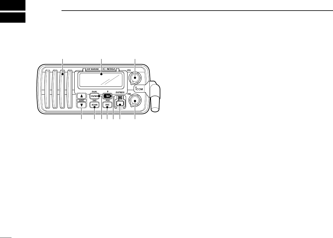
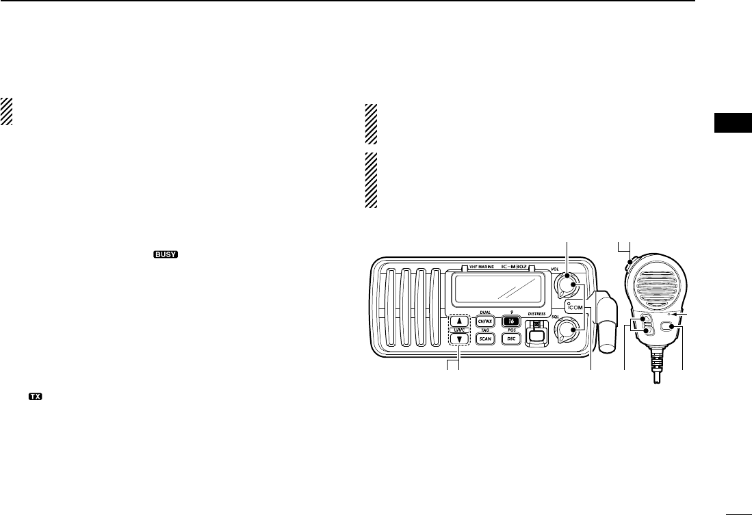
■Panel description
qPOWER/VOLUME CONTROL [VOL]
Turns power ON and OFF and adjusts the audio level. (p. 7)
wSQUELCH CONTROL [SQL]
Sets the squelch threshold level. (p. 7)
eDISTRESS SWITCH [DISTRESS]
Transmits distress call when pushed for 5 sec.
rCHANNEL 16/CALL CHANNEL SWITCH [16•9]
➥Selects channel 16 when pushed. (p. 5)
➥Selects call channel when pushed for 1 sec. (p. 5)
• “CALL” appears when call channel is selected.
➥Push for 3 sec. to enter call channel programming con-
dition when call channel is selected. (p. 8)
➥While pushing [CH/WX•DUAL], enters channel name
programming condition. (p. 8)
➥Enters set mode when pushed while turning power ON.
(p. 12)
tDSC/POSITION SWITCH [DSC/ENT•POS]
➥Selects the DSC menu when pushed.
➥Shows current position and time from a GPS receiver,
etc. when pushed for 1 sec.
yCHANNEL/WEATHER CHANNEL SWITCH
[CH/WX•DUAL]
➥Selects and toggles the regular channels and weather
channel when pushed momentarily. (p. 6)
➥Starts dualwatch or tri-watch when pushed for 1 sec.
(p.9)
➥Stops dualwatch or tri-watch when either is activated.
uSCAN SWITCH [SCAN•TAG]
➥Starts and stops normal or priority scan.
➥Sets or clears the displayed channel as a tag (scanned)
channel when pushed for 1 sec.
➥While pushing [HI/LO] on the microphone, clears all tag
channels in the selected channel group when pushed
for 3 sec.
iCHANNEL UP/DOWN SWITCHES [YY]/[ZZ]•[U/I/C]
➥Selects an operating channel. (p. 6)
➥Selects the SET mode condition of item. (p. 12)
➥While pushing [SCAN•TAG], push [Y]/[Z] to adjust the
brightness of the LCD and switch backlight.
➥Selects one of 3 regular channels in sequence when
both switch are pushed. (p. 6)
• International, U.S.A. and Canadian channels are available for
regular channels.
Speaker Function display q
wi u ytr e
!IC-M302_draft.qxd 03.9.1 6:02 PM Page 2 (1,1)
3
2
PANEL DESCRIPTION
New2001
2
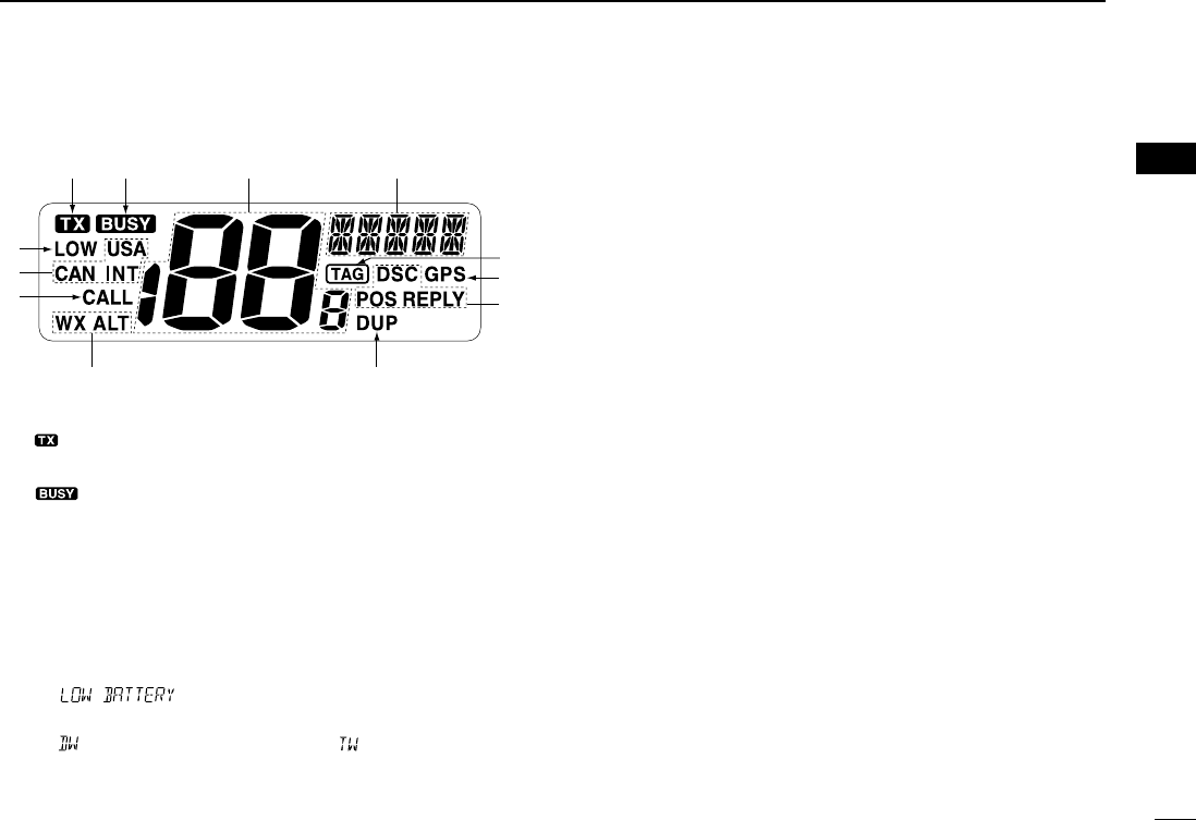
■Function display
qTRANSMIT INDICATOR (p. 7)
“” appears while transmitting.
wBUSY INDICATOR (p. 7)
“” appears when receiving a signal or when the
squelch opens.
eCHANNEL NUMBER READOUT
➥Indicates the selected operating channel number. “A”
appears when a simplex channel is selected. (p.6)
➥In set mode, indicates the selected condition. (p. 12)
rCHANNEL NAME INDICATOR
➥Channel name appears if programmed. (p. 8)
➥“” scrolls when the battery voltage drops
to approx. 10 V DC or below.
➥“” blinks during dualwatch; “” blinks during tri-
watch. (p. 9)
tTAG CHANNEL INDICATOR (p. 11)
Appears when a tag channel is selected.
yGPS INDICATOR
➥“GPS” appears while valid position data is received.
➥“GPS” blinks when invalid position data is received.
➥“GPS” disappears when no GPS receiver is connected.
uDSC INDICATOR
➥Indicates the DSC status.
iDUPLEX INDICATOR (p. 6)
Appears when a duplex channel is selected.
oWEATHER CHANNEL INDICATOR (p. 6)
➥“WX” appears when a weather channel is selected.
➥“WX ALT” appears when the weather alert function is in
use; blinks when an alert tone is received.
!0 CALL CHANNEL INDICATOR
“CALL” appears when the call channel is selected. (p. 5)
!1 CHANNEL GROUP INDICATOR
Indicates whether a U.S.A. (USA), International (INT), or
Canadian (CANADA) channel is in use.
!2 LOW POWER INDICATOR (p. 7)
“LOW” appears when low power is selected.
t
werq
u
y
io
!0
!2
!1
!IC-M302_draft.qxd 03.9.1 6:02 PM Page 3 (1,1)

4
2PANEL DESCRIPTION
New2001
■Microphone
qPTT SWITCH [PTT]
Push and hold to transmit; release to receive. (p. 7)
wCHANNEL UP/DOWN SWITCHES [YY]/[ZZ]
Push either switch to change the operating memory chan-
nel, set mode contents, etc. (pgs. 6, 12)
eTRANSMIT POWER SWITCH [HI/LO]
Toggles high and lower power when pushed. (p. 7)
•Some channels are set to low power only.
Microphone
w
q
e
!IC-M302_draft.qxd 03.9.1 6:02 PM Page 4 (1,1)
5
3
BASIC OPERATION
2
3
■Channel selection
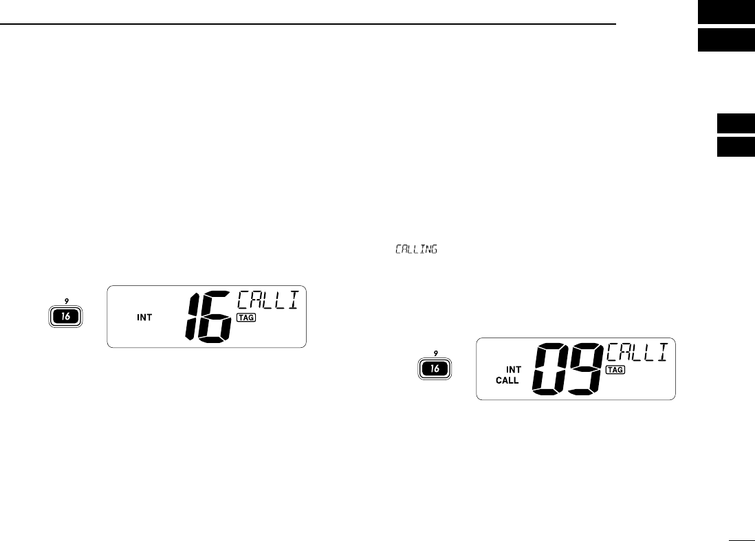
ïïChannel 16
Channel 16 is the distress and safety channel. It is used for
establishing initial contact with another station and for emer-
gency communications. Channel 16 is monitored during both
dualwatch and tri-watch. While standing by, you must monitor
Channel 16.
➥Push [16•9] momentarily to select channel 16.
➥Push [CH/WX•DUAL] to return to the condition before select-
ing Channel 16, or push [Y]/[Z] to select operating channel.
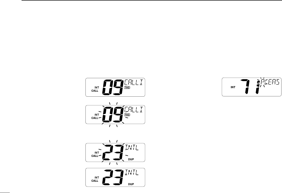
ïïChannel 9 (Call channel)
Each regular channel group has a separate leisure-use call
channel. The call channel is monitored during tri-watch. The
call channels can be programmed (p. 8) and are used to store
your most often used channels in each channel group for
quick recall.
➥Push [16•9] for 1 sec. to select the call channel of the se-
lected channel group.
•“ ” and call channel number appear.
•Each channel group may have an independent call channel after
programming a call channel.
➥Push [CH/WX•DUAL] to return to the condition before se-
lecting call channel, or push [Y]/[Z] to select an operating
channel.
for 1 sec.
Push
Push
!IC-M302_draft.qxd 03.9.1 6:02 PM Page 5 (1,1)
6
3BASIC OPERATION
New2001
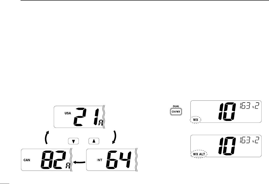
ïïU.S.A.,Canadian and international channels
There are 57 U.S.A., 61 Canadian and 57 international chan-
nels.These channel groups may be specified for the operating
area.
qPush [CH/WX•DUAL] to select a regular channel.
•If a weather channel appears, push [CH/WX•DUAL] again.
wPush both [Y] and [Z] to change the channel group, if
necessary.
•U.S.A., International (INT) and Canadian channels can be se-
lected in sequence.
ePush [Y] or [Z] to select a channel.
•“DUP” appears for duplex channels.
•“A” appears for simplex channels.
ïïWeather channels
There are 10 weather channels. Used for monitoring weather
channels from the NOAA (National Oceanographic and At-
mospheric Administration) broadcasts.
The transceiver can detect a weather alert tone on the se-
lected weather channel while receiving the channel, during
standby on a regular channel or while scanning. (p. 13)
qPush [CH/WX•DUAL] once or twice to select a weather
channel.
•“WX” appears when a weather channel is selected.
• “WX ALT” appears when the weather alert function is in use.
(p. 13)
wPush [Y] or [Z] to select a channel.
Push
once or twice
When weather alert is OFF.
When weather alert is ON.
U.S.A. channels
Canadian channels International channels
Push and
!IC-M302_draft.qxd 03.9.1 6:02 PM Page 6 (1,1)
7
3
BASIC OPERATION
New2001
3
■Receiving and transmitting
CAUTION: Transmitting without an antenna may dam-
age the transceiver.
qRotate [VOL] to turn power ON.
wSet the audio and squelch levels.
➥Rotate [SQL] fully counterclockwise in advance.
➥Rotate [VOL] to adjust the audio output level.
➥Rotate [SQL] clockwise until the noise disappears.
eTo change the channel group, push both [Y] and [Z]. (p. 6)
rPush [Y]/[Z] to select the desired channel. (p. 6)
•When receiving a signal, “” appears and audio is emitted
from the speaker.
•Further adjustment of [VOL] may be necessary at this point.
tPush [HI/LO] on the microphone to select the output power
if necessary.
•“LOW” appears when low power is selected.
•Choose high power for longer distance communications.
•Some channels are for low power only.
yPush and hold [PTT] to transmit, then speak into the mi-
crophone (M).
•“ ” appears.
•Channel 70 cannot be used for transmission (for GMDSS use).
uRelease [PTT] to receive.
Simplex channels, 3, 21, 23, 61, 64, 81, 82 and 83 CAN-
NOT be lawfully used by the general public in U.S.A. wa-
ters.
IMPORTANT: To maximize the readability of your trans-
mitted signal, pause a few sec. after pushing [PTT], hold
the microphone 2 to 4 inches (5 to 10 cm) from your mouth
and speak to Mat a normal voice level.
u
wr tre
M
qy
!IC-M302_draft.qxd 03.9.1 6:02 PM Page 7 (1,1)
8
3BASIC OPERATION
New2001
■Call channel programming
The call channel is used to select Channel 9, however, you
can program your most often-used channels in each channel
group for quick recall.
qPush both [Y] and [Z] one or more times to select the de-
sired channel group (U.S.A., International, Canada) to be
programmed.
wPush [16•9] for 1 sec. to se-
lect the call channel of the
selected channel group.
•“CALL” and call channel
number appear.
ePush [16•9] again for 3
sec. (until a long beep
changes to 2 short beeps)
to enter call channel pro-
gramming condition.
•Channel number starts
blinking.
rPush [Y]/[Z] to select the
desired channel.
tPush [16•9] to program
the displayed channel as
the call channel.
•Push [CH/WX•DUAL] to can-
cel.
•The channel number stops
blinking.
■Channel names
Memory channels can be tagged with alphanumeric names
of up to 10 characters each.
Capital letters, small letters (except f, j, p, s, y, x, z), 0 to 9,
some symbols (= ✱+ – . /) and space can be used.
qSelect the desired memory channel.
•Cancel dual watch, tri-watch or scan in advance.
wWhile pushing [CH/WX•
DUAL], push [16•9] to edit
the channel name.
•A cursor and the first char-
acter starts blinking alter-
nately.
eSelect the desired character by pushing [Y]/[Z].
rPush [CH/WX•DUAL] or [16•9] for cursor movement.
tRepeat steps eand rto input all characters.
yPush [DSC•POS] to set the channel name.
uRepeat steps qto yto program other memory channel
names, if desired.
■Microphone lock function
The microphone lock function electrically locks the [Y]/[Z]
and [HI/LO] switches on the supplied microphone. This pre-
vents accidental channel changes and function access.
➥While pushing [HI/LO] on the microphone, turn power ON
to toggle the lock function ON and OFF.
!IC-M302_draft.qxd 03.9.1 6:02 PM Page 8 (1,1)
9
4
DUAL WATCH/TRI-WATCH
3
4
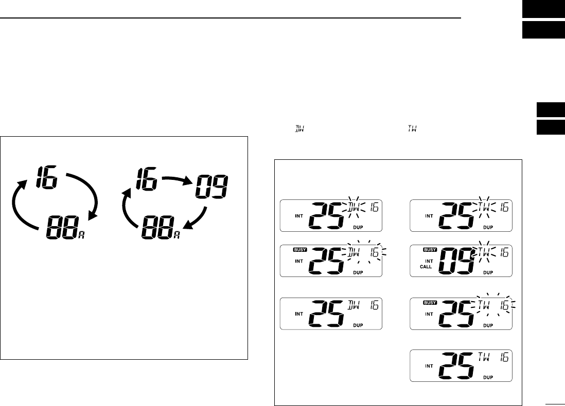
■Description
Dualwatch monitors Channel 16 while you are receiving
another channel; tri-watch monitors Channel 16 and the call
channel while receiving another channel.
■Operation
qSelect the desired operating channel.
wPush [SCN•DUAL] for 1 sec. to start dualwatch or tri-watch
(depending on SET mode setting).
•“ ” blinks during dualwatch; “” blinks during tri-watch.
•A beep tone sounds when a signal is received on Channel 16.
eTo cancel dualwatch/tri-watch, push [SCN•DUAL] again.
DUALWATCH/TRI-WATCH SIMULATION
•If a signal is received on Channel 16, dualwatch/tri-watch
pauses on Channel 16 until the signal disappears.
•If a signal is received on the call channel during tri-watch,
tri-watch becomes dualwatch until the signal disappears.
•To transmit on the selected channel during dualwatch/tri-
watch, push and hold [PTT].
Dualwatch Tri-watch
Call channel
[Example]:
Tri-watch starts. Tri-watch starts.
Signal is received on
Channel 16 takes priority.
Signal is received on call
channel.
Dualwatch resumes after
the signal disappears.
Signal is received on
Channel 16 takes priority.
Tri-watch resumes after
the signal disappears.
Operating dualwatch on
INT channel 25
Operating tri-watch on
INT channel 25
!IC-M302_draft.qxd 03.9.1 6:02 PM Page 9 (1,1)
10
SCAN OPERATION
New2001
5
■Scan types
Scanning is an efficient way to locate signals quickly over a
wide frequency range. The transceiver has priority scan and
normal scan.
When the weather alert function is in use, the selected
weather channel is checked while scanning. (p. 13)
Set the tag channels (scanned channel) before scanning.
Clear the tag channels which inconveniently stop scanning,
such as digital communication use.
Choose priority or normal scan in SET mode. (p. 13)
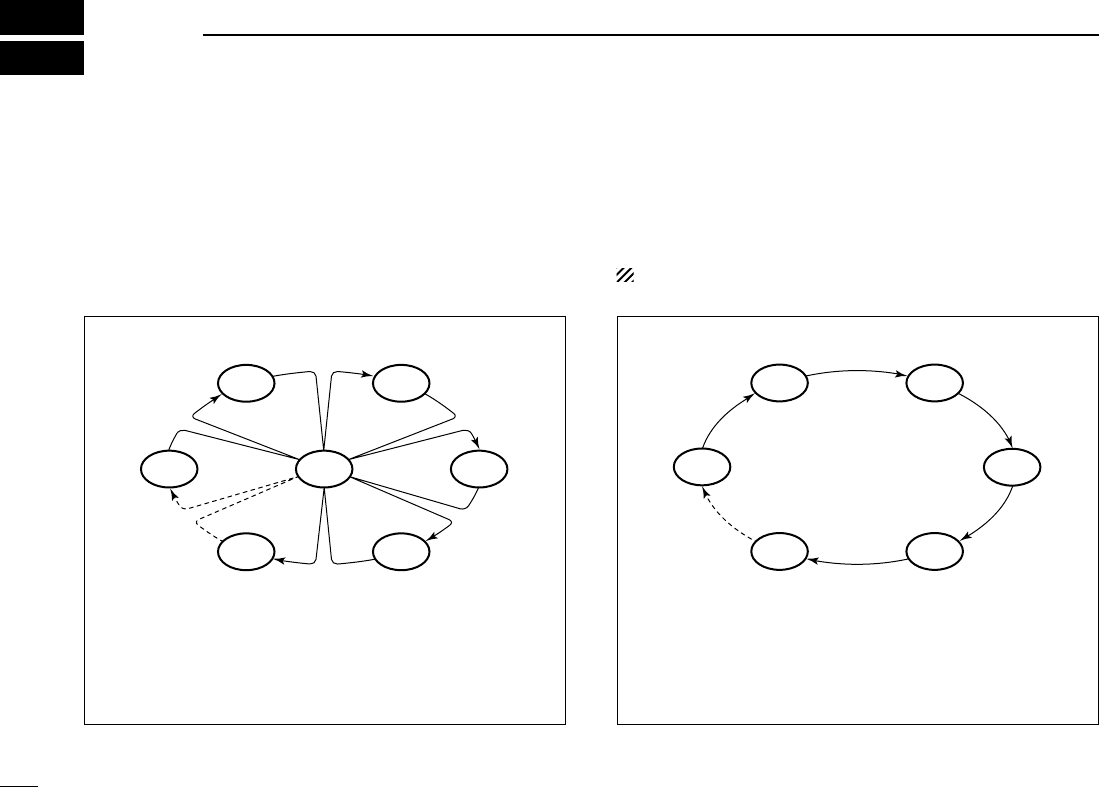
PRIORITY SCAN
Priority scan searches through all tag channels in sequence
while monitoring Channel 16. When a signal is detected on
Channel 16, scan pauses until the signal disappears; when
a signal is detected on a channel other than Channel 16,
scan becomes dualwatch until the signal disappears.
CH 06
CH 01
CH 16
CH 02
CH 05 CH 04
CH 03
NORMAL SCAN
Normal scan, like priority scan, searches through all tag
channels in sequence. However, unlike priority scan, Chan-
nel 16 is not checked unless Channel 16 is set as a tag
channel.
CH 01 CH 02
CH 06
CH 05 CH 04
CH 03
!IC-M302_draft.qxd 03.9.1 6:02 PM Page 10 (1,1)
11
5
SCAN OPERATION
New2001
5
■Setting tag channels
For more efficient scanning, add desired channels as tag
channels or clear the tag for unwanted channels.
Non-tag channels will be skipped during scanning. Tag chan-
nels can be assigned to each channel group (USA, INT, CAN)
independently.
qSelect the desired channel group (USA, INT, CAN) by
pushing both [Y] and [Z], if desired.
wSelect the desired channel to set as a tag channel.
ePush [SCAN•TAG] for 1 sec. to set the displayed channel
as a tag channel.
•“ ” appears in the function display.
rTo cancel the tag channel setting, push [SCAN•TAG] for 1
sec.
•“ ” disappears.
✔Clearing all tag channels in the selected channel group
While pushing [HI/LO] on the microphone, push [SCAN•TAG]
for 3 sec. to clear all tag channels in the selected channel
group.
■Starting a scan
Set scan type (priority or normal) and scan resume timer in
advance, using SET mode. (p. 13)
qSet tag channels as described at left.
wMake sure the squelch is closed to start a scan.
eSelect the desired channel group (USA, CAN, INT) by
pushing both [Y] and [Z], if desired.
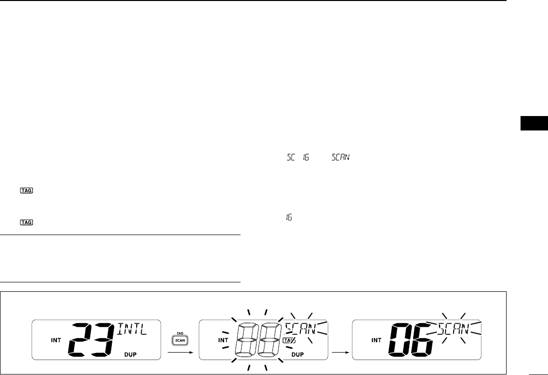
rPush [SCAN•TAG] to start priority or normal scan.
•“ ” or “” appears in the function display.
•When a signal is detected, scan pauses until the signal disap-
pears or resumes after pausing 5 sec. according to set mode
setting. (Channel 16 is still monitored during priority scan.)
•Push [Y] or [Z] to check the scanning tag channels, to change
the scanning direction or resume the scan manually.
•“ ” on channel name indicator blinks and a beep tone sounds
when a signal is received on Channel 16 during priority scan.
tTo stop the scan, push [SCAN•TAG].
Scan starts. When a signal is received.
Push
[Example]: Starting a normal scan.
!IC-M302_draft.qxd 03.9.1 6:02 PM Page 11 (1,1)
12
SET MODE
New2001
6
■Set mode programming
Set mode is used to change the conditions of the trans-
ceiver’s functions: scan type (normal or priority), scan resume
timer, weather alert, dual/tri-watch, DSC watch, transceiver’s
beep tone and Auto ACK.
Available functions may differ depending on dealer setting.
DSET mode operation
qTurn power OFF.
wWhile pushing [16•9], turn power ON to enter SET mode.
• “” appears on channel name indicator.
eAfter the display appears, release [16•9].
rPush [16•9] to select the desired item, if necessary.
tPush [Y]/[Z] to select the desired condition of the item.
yTurn power OFF, then ON again to exit set mode.
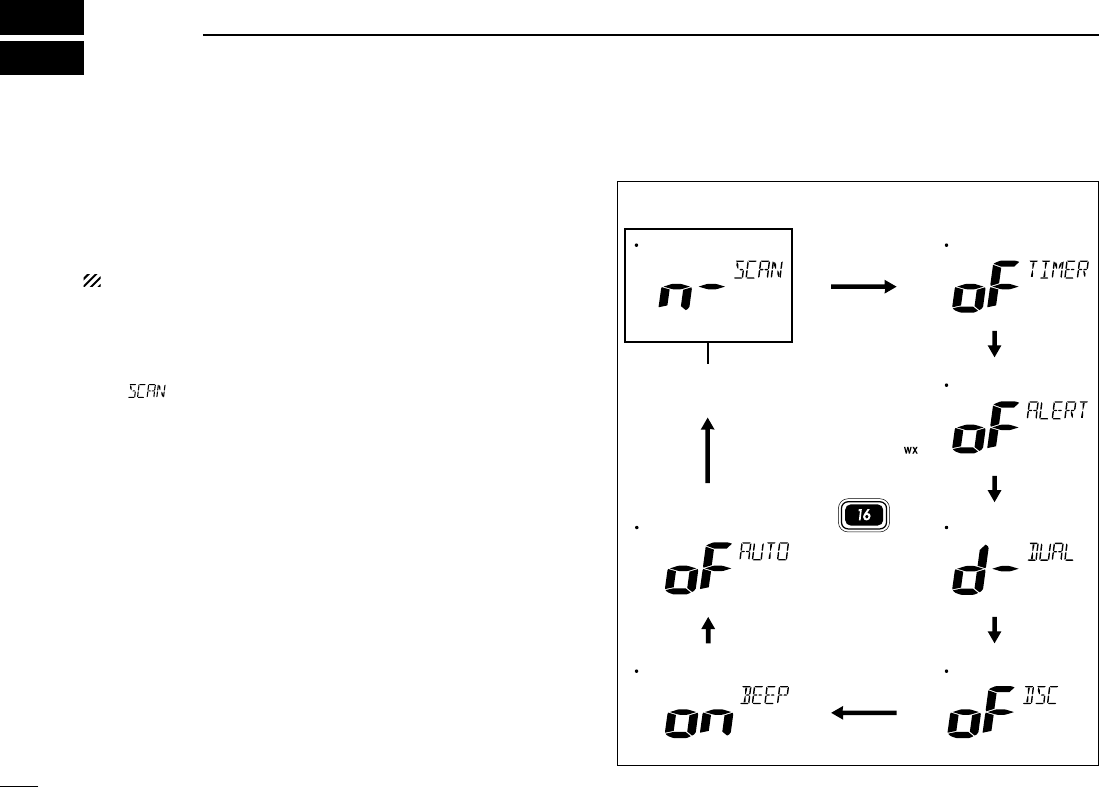
DSET MODE CONSTRUCTION
Starting item
Push
Scan mode
Auto acknowledgement
Beep tone DSC watch
Dual/tri watch
Weather alert
Scan resume timer
!IC-M302_draft.qxd 03.9.1 6:02 PM Page 12 (1,1)

13
6
SET MODE
New2001
6
■SET mode items
DScan type
The transceiver has 2 scan types: normal scan and priority
scan. Normal scan searches all tag channels in the selected
channel group. Priority scan searches all tag channels in se-
quence while monitoring Channel 16.
DDScan resume timer
The scan resume timer can be selected as a pause (OFF) or
timer scan (ON). When OFF is selected, the scan pauses
until the signal disappears. When ON is selected, the scan
pauses 5 sec. and resumes even if a signal has been re-
ceived on channels except for Channel 16.
DDWeather alert
An NOAA broadcast station transmits a weather alert tone be-
fore important weather information. When the weather alert
function is turned ON, the transceiver detects the alert, then
the “WX ALT” indicator blinks until the transceiver is operated.
The previously selected (used) weather channel is checked
any time during standby or while scanning.
•“WX ALT” appears instead of “WX” indication when the function is
set ON.
DDDual/Tri-watch
This item can be selected as dual watch or tri-watch. (p. 9)
Dual watch (default) Tri-watch
Weather alert OFF (default) Weather alert ON
Scan timer OFF (default) Scan timer ON
Normal scan (default) Priority scan
!IC-M302_draft.qxd 03.9.1 6:02 PM Page 13 (1,1)

14
6SET MODE
New2001
DDDSC watch
DSC watch monitors Channel 70 while you are receiving an-
other channel.
If a distress signal is received on Channel 70, the transceiver
monitors Channel 16 and 70 alternately until the distress sig-
nal disappears. If a signal is received on another channel,
DSC watch pauses until the signal disappears.
This function may not be available for some channel
groups depending on dealer setting.
DDBeep tone
You can select silent operation by turning beep tones OFF or
you can have confirmation beeps sound at the push of a
switch by turning beep tones ON.
DDAuto acknowledgement
The transceiver automatically transmits position reply or po-
sition report reply when a position request or position report
call is received, respectively when this function is turned ON.
Auto acknowledgement
OFF (default)
Auto acknowledgement
ON
Beep tone ON (default) Beep tone OFF
DSC watch OFF (default) DSC watch ON
!IC-M302_draft.qxd 03.9.1 6:02 PM Page 14 (1,1)

15
7
TROUBLESHOOTING
6
7
PROBLEM POSSIBLE CAUSE SOLUTION REF.
No sound from speaker. •Squelch level is too deep.
•Volume level is too low.
•Speaker has been exposed to water.
p. 7
p. 7
—
•Set squelch to the threshold point.
•Set [VOL] to a suitable level.
•Drain water from the speaker.
The transceiver does
not turn ON.
•Bad connection to the battery pack. p. ?•Check the connection to the transceiver.
Transmitting is impossi-
ble, or high power can
not be selected.
•Some channels are for low power or re-
ceive only.
•The output power is set to low.
pgs. 5,
6, 16
p. 7
•Change channels.
•Push [HI/LO] on the microphone to select
high power.
Scan does not start. •“TAG” channels are not programmed. •Set the desired channels as “TAG” channels. p. 11
No beeps. •Beep tones are turned OFF.
•The squelch is open.
•Turn the beep tone ON in SET mode.
•Set squelch to the threshold point.
p. 14
p. 7
Distress call cannot be
transmitted.
•MMSI (DSC self ID) code is not pro-
grammed.
•Program the MMSI (DSC self ID) code. p. ?
!IC-M302_draft.qxd 03.9.1 6:02 PM Page 15 (1,1)

16
CHANNEL LIST
New2001New2001
8
Channel number
USA CAN
Transmit
Receive
01 156.050 160.650
01A 156.050 156.050
02 156.100 160.700
03 156.150 160.750
03A 156.150 156.150
156.200 160.800
04A 156.200 156.200
156.250 160.850
05A 05A 156.250 156.250
06 06 156.300 156.300
156.350 160.950
07A 07A 156.350 156.350
08 08 156.400 156.400
09 09 156.450 156.450
10 10 156.500 156.500
11 11 156.550 156.550
12 12 156.600 156.600
13
*2
13
*1
156.650 156.650
14 14 156.700 156.700
15
*2
15
*1
156.750 156.750
16 16 156.800 156.800
17
*1
17
*1
156.850 156.850
156.900 161.500
18A 18A 156.900 156.900
Frequency (MHz)
INT
01
02
03
04
05
06
07
08
09
10
11
12
13
14
15
*1
16
17
18
Channel number Frequency (MHz)
USA CAN
Transmit
Receive
19A 19A 156.950 156.950
20 20
*1
157.000 161.600
21 157.050 161.650
21A 21A 157.050 157.050
157.100 161.700
22A 22A 157.100 157.100
23 157.150 161.750
23A 157.150 157.150
24 24 157.200 161.800
25 25 157.250 161.850
26 26 157.300 161.900
27 27 157.350 161.950
28 28 157.400 162.000
60 156.025 160.625
156.075 160.675
61A 61A 156.075 156.075
156.125 160.725
62A 156.125 156.125
156.175 160.775
63A 156.175 156.175
64 156.225 160.825
INT
20
21
22
23
24
25
26
27
28
60
61
62
63
64
20A 157.000 157.000
Channel number
66A
Frequency (MHz)
66A
*1
USA CAN
Transmit
Receive
64A 64A 156.225 160.825
65A 65A 156.275 156.275
156.325 160.925
67
*2
67 156.375 156.375
68 68 156.425 156.425
69 69 156.475 156.475
70
*3
70
*3
156.525 156.525
71 71 156.575 156.575
72 72 156.625 156.625
73 73 156.675 156.675
74 74 156.725 156.725
77
*1
77
*1
156.875 156.875
156.925 161.525
78A 78A 156.925 156.925
156.975 161.575
79A 79A 156.975 156.975
157.025 161.625
80A 80A 157.025 157.025
157.075 161.675
81A 81A 157.075 157.075
157.125 161.725
82A 82A 157.125 157.125
INT
65A
66
67
68
69
70
*3
71
72
73
74
77
78
79
80
81
82
156.325 156.32566A
Channel number
84A
Frequency (MHz)
USA CAN
Transmit
Receive
83A 83A 157.175 157.175
84 84 157.225 161.825
85 85 157.275 161.875
85A 157.275 157.275
86 86 157.325 161.925
86A 157.325 157.325
87 87 157.375 161.975
87A 157.375 157.375
88 88 157.425 162.025
88A 157.425 157.425
INT
84
85
86
87
88
157.225 157.225
WX channel
4
Frequency (MHz)
Transmit Receive
1 RX only 162.550
2 RX only 162.400
3 RX only 162.475
5 RX only 162.450
6 RX only 162.500
7 RX only 162.525
8 RX only 161.650
9 RX only 161.775
10 RX only 163.275
RX only 162.425
*1
Low power only.
*3
Receive only.
156.950 161.55019
21b Rx only 161.650
25b Rx only 161.850
156.275 160.87565
28b Rx only 162.000
83 157.175 161.77583
83b Rx only 161.775
*2
Momentary high power.
NOTE: Simplex channels, 3, 21, 23, 61, 64, 81, 82 and 83 CANNOT
be lawfully used by the general public in U.S.A. waters.
!IC-M302_draft.qxd 03.9.1 6:02 PM Page 16 (1,1)

17
9
SPECIFICATIONS AND OPTIONS
8
9
New2001
■Specifications
ïïGeneral
•Frequency coverage :
Transmit 156.025–157.425 MHz
Receive 156.050–163.275 MHz
•Mode : FM (16K0G3E)
DSC(16K0G2B)
•Channel spacing : 25 kHz
•Current drain (at 13.8 V) : TX high 5.5 A max.
Max. audio 1.5 A max.
•Power supply requirement : 13.8 V DC
•Frequency stability : ±10 ppm (–20°C to +60°C;–4°F to +140°F)
•Dimensions : 153(W) ×67(H) ×141.6(D) mm
(Projection not included) 6 1/32(W) ×2 5/8(H)×5 9/16(D) in
•Weight : 825 g ; 1.8 lb
ïïTransmitter
•Output power : 25 W and 1 W
•Modulation system : Variable reactance frequency modulation
•Max. frequency deviation : ±5.0 kHz
•Spurious emissions : Less than –70 dB
ïïReceiver
•Receive system : Double conversion superheterodyne
•Sensitivity (12 dB SINAD) : Less than 0.22µV (typical)
•Squelch sensitivity : Less than 0.22µV (typical)
•Intermodulation rejection ratio : More than 70 dB
•
Spurious response rejection ratio
: More than 70 dB
•Adjacent channel selectivity : More than 70 dB
•Audio output power : More than 4.5W at 10% distortion with a 4
Ωload
All stated specifications are subject to change without notice or
obligation.
■Options
•MB-69 FLUSH MOUNT
For mounting the transceiver to a panel.
•MB-92 DUST COVER
For mounting the transceiver to a front panel to avoid expo-
sure the keys and knobs to water when the transceiver is not
used.
!IC-M302_draft.qxd 03.9.1 6:02 PM Page 17 (1,1)

1-1-32 Kamiminami, Hirano-ku, Osaka 547-0003 Japan
A-6308D-1US
Printed in Japan
©2003 Icom Inc.
New2001
!IC-M302_draft.qxd 03.9.1 6:02 PM Page 18 (1,1)