ICOM orporated 269100 VHF Marine Transceiver User Manual IC M32 2
ICOM Incorporated VHF Marine Transceiver IC M32 2
UserManual.wiki
>
ICOM orporated
>
269100 User Manual
>
Manual revised in response to FCC correspondence 9722
Contents
1.
Manual
2.
Manual revised in response to FCC correspondence 9722
Manual revised in response to FCC correspondence 9722
Navigation menu
Upload a User Manual
Namespaces
Wiki Guide
HTML
PDF
Info
Views
User Manual
Discussion / Help
Navigation
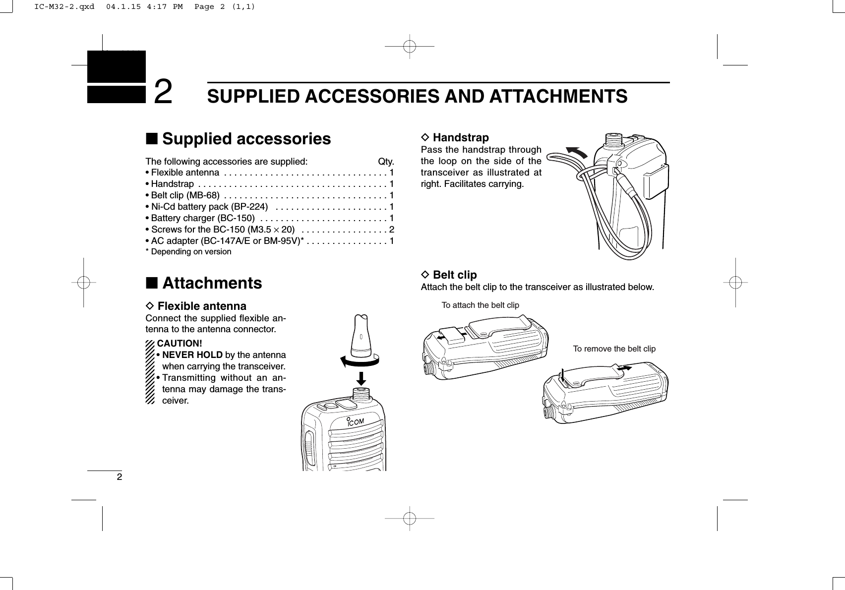
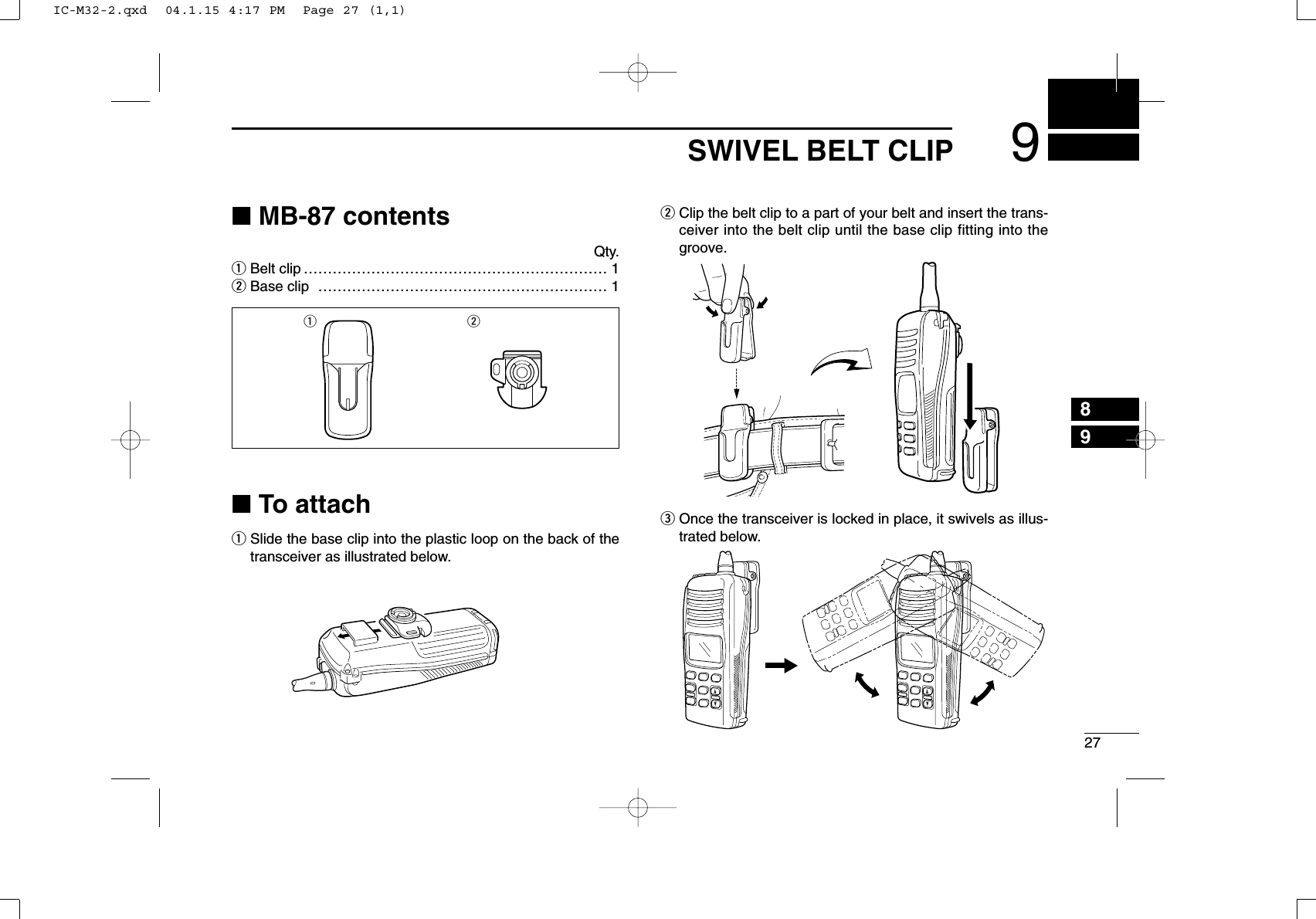
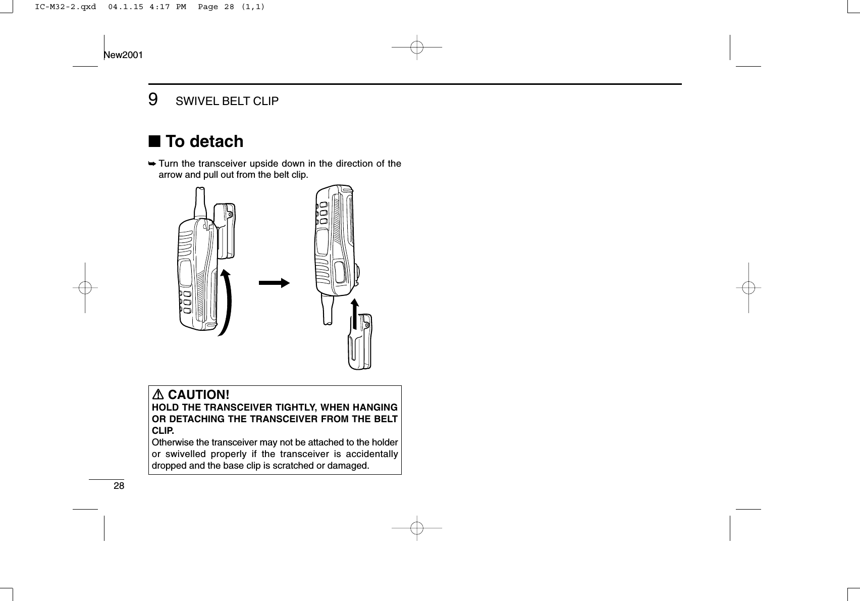
![4PANEL DESCRIPTIONNew20013■Front, top and side panelsqPOWER SWITCH [PWR]Push and hold to turn power ON and OFF.wANTENNA CONNECTOR (p. 2)Connects the supplied antenna.eSCAN/DUAL KEY [SCN•DUAL]•Starts and stops normal or priority scan. (p. 15)•Enters watch mode when pushed for 1 sec. (p. 16)• Exits watch mode when pushed during watch operation.(p. 16)rTRANSMIT POWER/LOCK KEY [H/L•LOCK]•Selects high or low power when pushed. (p. 11)•Toggles the lock function ON/OFF when pushed for 1sec. (p. 13)tVOLUME UP/DOWN KEYS [+]/[–]•[VOL]•Adjusts the volume level. (p. 10)• After pushing [SQL•MONI], push to adjust the squelchlevel. (p. 10)ySQUELCH KEY [SQL•MONI]•Push this key, then adjust the squelch level with [+]/[–].(p. 10)• Manually opens the squelch for monitoring the channelwhile pushed and held. (p. 13)•While pushing this key, turn power ON to enter the setmode. (p. 17)rqoui!0wyteMicrophoneFunction display (p. 6)SpeakerIC-M32-2.qxd 04.1.15 4:17 PM Page 4 (1,1)](https://usermanual.wiki/ICOM-orporated/269100.Manual-revised-in-response-to-FCC-correspondence-9722/User-Guide-389068-Page-10.png)
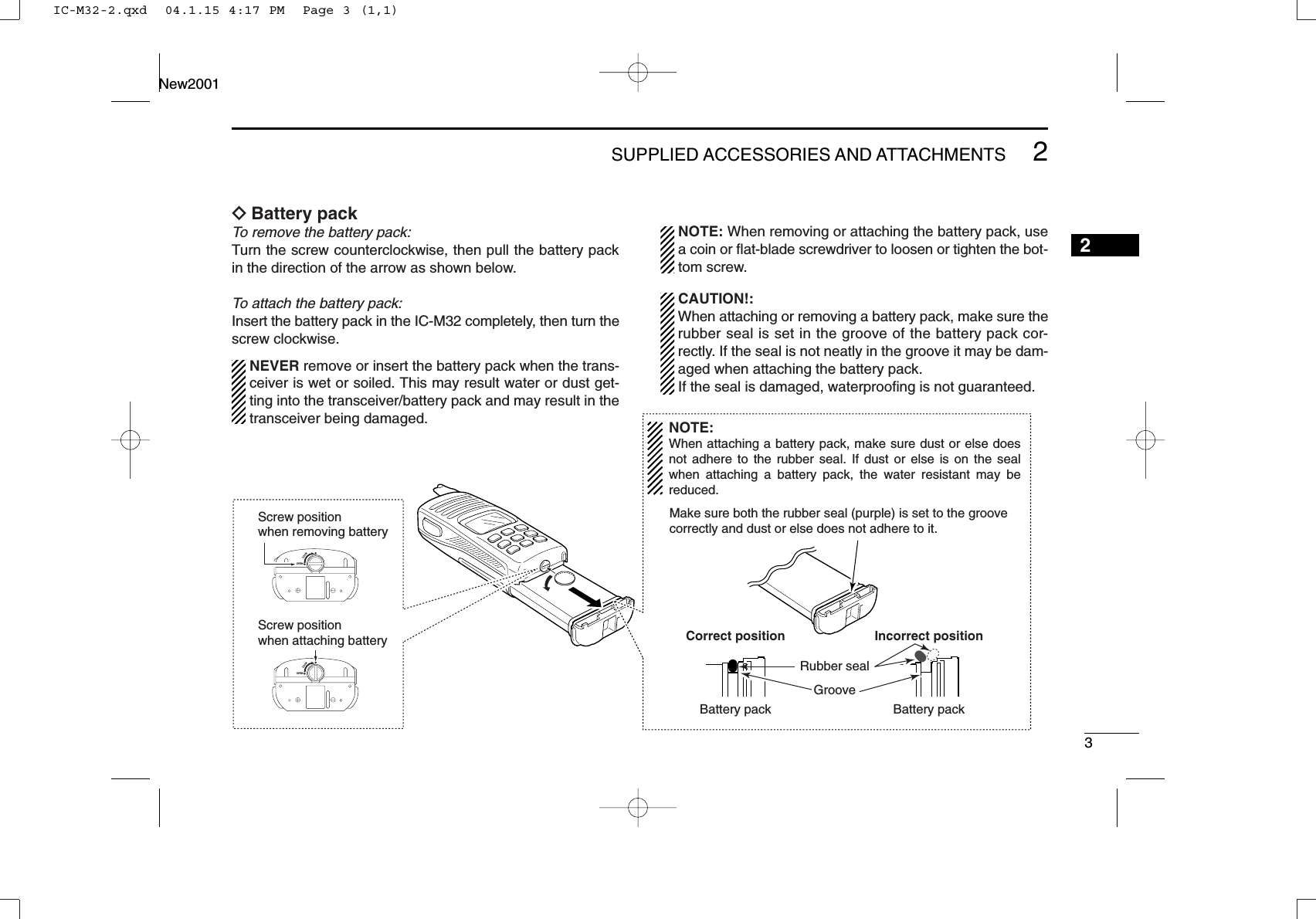
![53PANEL DESCRIPTIONNew20013uCHANNEL UP/DOWN KEYS [YY]/[ZZ]•[TAG]•Selects an operating channel. (pgs. 8, 9)•Selects the SET mode condition of the item. (p. 17)• Checks tag channels or changes scanning direction dur-ing scan. (p. 15)•Sets or clears the displayed channel as a tag (scanned)channel when pushed both keys for 1 sec. (p. 15)• While turning power ON, clears all tag channels in the se-lected channel group when both keys are pushed. (p. 15)iCHANNEL/WEATHER CHANNEL KEY [CH/WX•U/I/C]•Toggles the regular channels and weather channel whenpushed. (p. 9)•Selects one of 3 (or 2*) regular channel groups in se-quence when pushed for 1 sec. (p. 9)- U.S.A., International and Canadian* channels are available. *Canadian channels are available for the USA version only.•Push to return to the channel selection before selectingthe channel 16 or the call channel with [16•9].oCHANNEL 16 KEY [16•9]•Selects Channel 16 when pushed. (p. 8)•Selects the call channel when pushed for 1 sec. (p. 8)- Channel 9 is factory default.•Enters call channel programming condition when the callchannel is selected and this key is pushed for 3 sec. (p. 12)• Exits set mode when pushed during set mode operation.(p. 17)!0 PTT SWITCH [PTT]Push and hold to transmit; release to receive.IC-M32-2.qxd 04.1.15 4:17 PM Page 5 (1,1)](https://usermanual.wiki/ICOM-orporated/269100.Manual-revised-in-response-to-FCC-correspondence-9722/User-Guide-389068-Page-11.png)
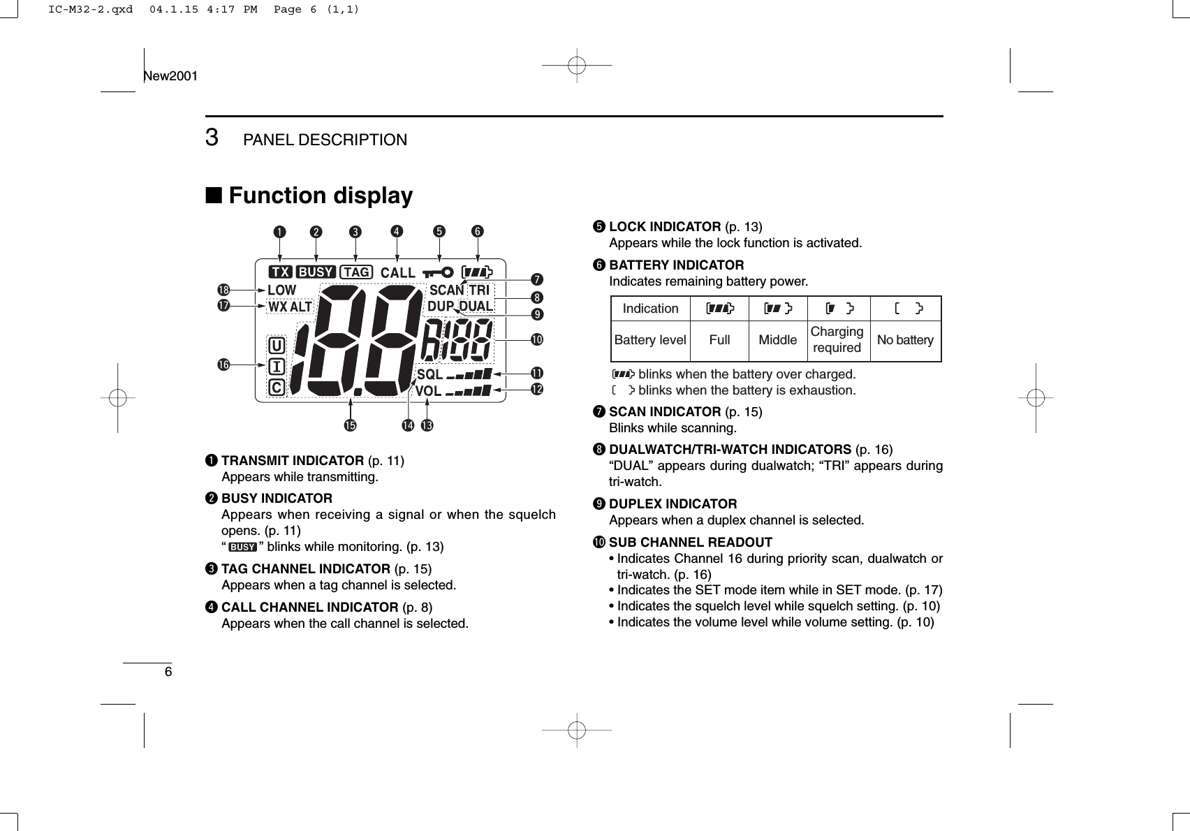
![8BASIC OPERATIONNew20014■Channel selectionIMPORTANT!: Prior to using the transceiver for the firsttime, the battery pack must be fully charged for optimumlife and operation. To avoid damage to the transceiver, turnthe power OFF while charging.DChannel 16Channel 16 (Distress channel) is used for establishing initialcontact with another station and for emergency communica-tions. Channel 16 is automatically monitored during both du-alwatch and tri-watch. While standing by, you must monitorChannel 16.qPush [16•9] to select Channel 16.wPush [CH/WX•U/I/C] to return to the condition before se-lecting Channel 16, or push [Y]/[Z] to select the operatingchannel.DChannel 9 (Call channel)Channel 9 is the leisure-use call channel. Each regular chan-nel group has separate call channels. In addition, the callchannel is monitored during tri-watch. The call channels canbe re-programmed (p. 12) and are used to store your mostoften used channels in each channel group for quick recall.qPush [16•9] for 1 sec. to select the call channel in the se-lected channel group.•“CALL” and the call channel number appear.•Each channel group may have its own call channel after pro-gramming a call channel. See the “Call channel programming”on p. 12 for details.wPush [CH/WX•U/I/C] to return to the condition before se-lecting Channel 9 (call channel), or push [Y]/[Z] to selectthe operating channel.9Pushfor 1 sec.9PushIC-M32-2.qxd 04.1.15 4:17 PM Page 8 (1,1)](https://usermanual.wiki/ICOM-orporated/269100.Manual-revised-in-response-to-FCC-correspondence-9722/User-Guide-389068-Page-14.png)
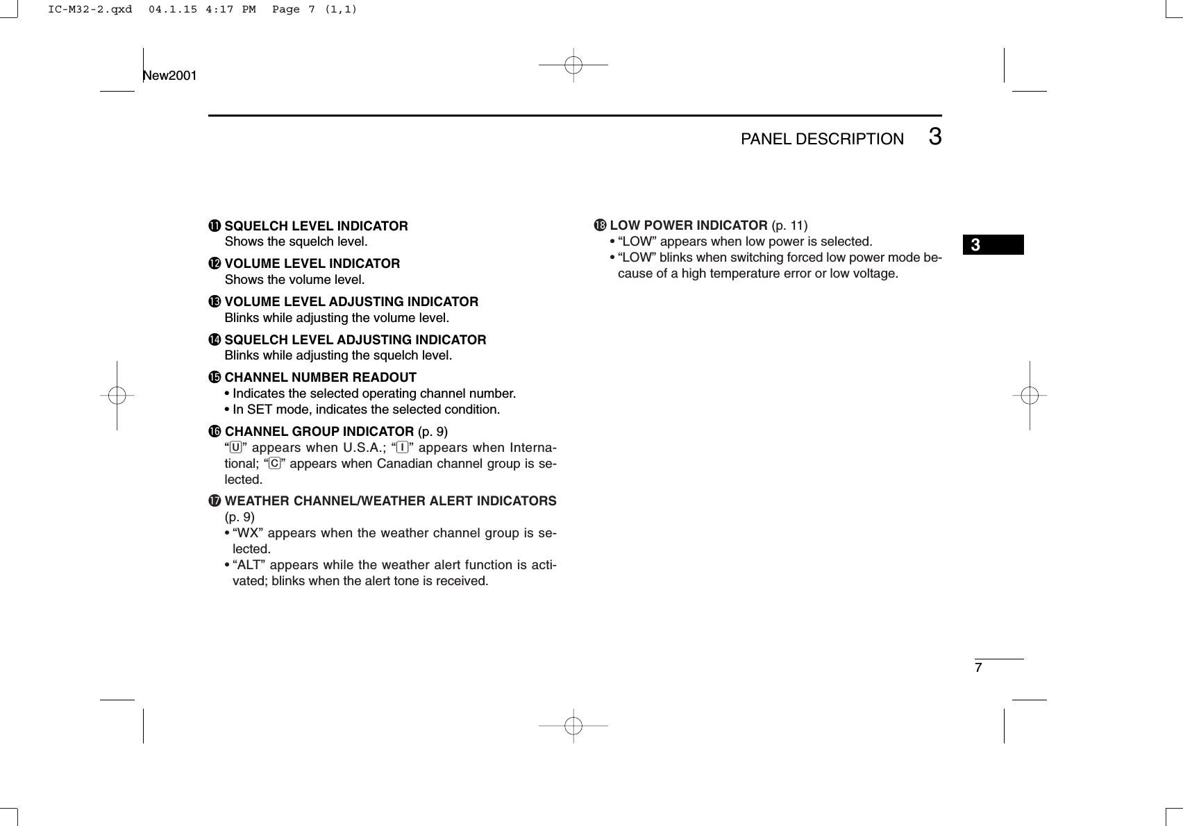
![94BASIC OPERATIONNew20014DU.S.A., International and Canadian channelsThere are 57 U.S.A., 57 International, and 61 Canadian chan-nels. These channel groups may be specified for the operat-ing area.qPush [CH/WX•U/I/C] to select a regular channel.•If a weather channel appears, push [CH/WX•U/I/C] again.wPush [Y]/[Z] to select a channel.•“DUP” appears for duplex channels.eTo change the channel group, push [CH/WX•U/I/C] for1 sec.•U.S.A., International and Canadian channels can be selected insequence.DWeather channelsThere are 10 weather channels. They are used for monitoringweather channels from the NOAA (National Oceanographicand Atmospheric Administration) broadcasts (reception ofweather channels possible in USA only).qPush [CH/WX•U/I/C] to select the weather channel group.wPush [Y]/[Z] to select a weather channel.ePush [CH/WX•U/I/C] to return to the condition before se-lecting the weather channel group.✔CONVENIENT!The IC-M32 can detect a weather alert tone on the selectedweather channel while in another channel (when the powersave function is turned ON) or during scanning. See the “SETmode items” on p. 18 for details.U/I/CPushU/I/CU/I/CU/I/CPush for 1 sec.U.S.A. channelsInternational channels Canadian channelsIC-M32-2.qxd 04.1.15 4:17 PM Page 9 (1,1)](https://usermanual.wiki/ICOM-orporated/269100.Manual-revised-in-response-to-FCC-correspondence-9722/User-Guide-389068-Page-15.png)
![104BASIC OPERATIONNew2001■Adjusting the volume levelThe volume level can be adjusted with [+]/[–].➥Push [+]/[–] to adjust the volume level.•“VOL” indicator starts blinking.• There are 32 volume levels to choose.• When no key is pushed for 5 sec., the transceiver returns to nor-mal condition.■Adjusting the squelch levelThe IC-M32 has a squelch level adjustment, even though thereis no control knob for it. In order to receive signals properly, aswell as for the scan to function effectively, the squelch must beadjusted to the proper level.qPush [SQL•MONI], then adjust the squelch level with [+]/[–].- “SQL” indicator starts blinking.- There are 11 squelch levels to choose from: OP is completelyopen; 10 is tight squelch; 1 is loose squelch level.- When no key is pushed for 5 sec., the transceiver returns to nor-mal condition.wPush [SQL•MONI] again to return to normal condition.✔CONVENIENT!The squelch level adjustment key can be selected from[Y]/[Z] and [+]/[–] with following operation.• While pushing both [SQL•MONI] and [Y], turn the power ONto set [Y]/[Z] to the squelch level adjustment key.• While pushing both [SQL•MONI] and [+], turn the power ONto set [+]/[–] to the squelch level adjustment key.Blinks during squelch level adjustment.Indicates the squelch level.Blinks during volume level adjustment.Indicates the volume level.IC-M32-2.qxd 04.1.15 4:17 PM Page 10 (1,1)](https://usermanual.wiki/ICOM-orporated/269100.Manual-revised-in-response-to-FCC-correspondence-9722/User-Guide-389068-Page-16.png)
![114BASIC OPERATIONNew20014■Receiving and transmittingqPush and hold [PWR] to turn power ON.wSet the volume and squelch levels.➥Push [SQL•MONI], and push [–] to open the squelch.➥Push [SQL•MONI] to stop “SQL” indicator blinking, thenpush [+]/[–] to set the volume level.➥Push [SQL•MONI], and push [+]/[–] to set the squelchlevel.ePush [Y]/[Z] to select the desired channel.- When receiving a signal, “” appears and audio is emittedfrom the speaker.- Further adjustment of the volume may be necessary at this point.rPush [H/L•LOCK] to select the output power if necessary.- “LOW” appears when low power is selected; no indication whenhigh power is selected.- Choose low power to conserve battery power, choose highpower for longer distance communications.- Some channels are for low power only.tPush and hold [PTT] to transmit, then speak into themicrophone.- “”appears.- Channel 70 cannot be used for transmission.yRelease [PTT] to receive.IMPORTANT: To maximize the readability of your trans-mitted signal, pause a few sec. after pushing [PTT], holdthe microphone 5 to 10 cm (2 to 4 inches) from your mouthand speak into the microphone at a normal voice level.NOTE: The transceiver has a power save function to con-serve the battery power. The power save function activatesautomatically when no signal is received for 5 sec.For U.S.A version: To prevent accidental prolonged trans-mission, etc., the IC-M32 has a time-out timer function.This timer cuts a transmission OFF after 5 min. of continu-ous transmission.q Power ONeSet channelt Push to transmity Release to receive r Set output powerw Set volumew Set the squelch levelw Set the squelch levelMicrophoneCAUTION: Transmitting without an antenna maydamage the transceiver.IC-M32-2.qxd 04.1.15 4:17 PM Page 11 (1,1)](https://usermanual.wiki/ICOM-orporated/269100.Manual-revised-in-response-to-FCC-correspondence-9722/User-Guide-389068-Page-17.png)
![124BASIC OPERATIONNew2001■Call channel programmingThe call channel key is used to select Channel 9 by default,however, you can program your most often-used channel ineach channel group for quick recall.qPush [CH/WX•U/I/C] for 1 sec.several times to select the desiredchannel group (USA, INT, CAN) tobe programmed.wPush [16•9] for 1 sec. to select thecall channel.•“CALL” and call channel number ap-pear.ePush [16•9] again for 3 sec. (untila long beep changes to 2 shortbeeps) to enter call channel pro-gramming condition.•Call channel number to be pro-grammed flashes.rPush [Y]/[Z] to select the desiredchannel.tPush [16•9] to program the dis-played channel as the call chan-nel.•The call channel number stop flash-ing.IC-M32-2.qxd 04.1.15 4:17 PM Page 12 (1,1)](https://usermanual.wiki/ICOM-orporated/269100.Manual-revised-in-response-to-FCC-correspondence-9722/User-Guide-389068-Page-18.png)
![134BASIC OPERATIONNew20014■Lock functionThis function electronically locks all keys (except for [+]/[–],[PTT], [SQL•MONI] and [H/L•LOCK]) to prevent accidentalchannel changes and function access.➥Push [H/L•LOCK] for 1 sec. to turn the lock function ON andOFF.■Automatic backlightingThis function is convenient for nighttime operation. The auto-matic backlighting can be activated in SET mode. (p. 20)➥Push any key except for [PTT] to turn the backlighting ON.•The backlighting is automatically turned OFF after 5 sec. of in-activity.■Monitor functionThe monitor function releases the noise squelch mute. Seep. 19 for details of the monitor switch action.➥Push [SQL•MONI] for 1 sec. to activate the monitor func-tion.•“ ” blinks and audio is emitted.MONIPushfor 1 sec.Blinks while the monitor function is used.LOCKPushfor 1 sec.Appears while the lock function is used.IC-M32-2.qxd 04.1.15 4:17 PM Page 13 (1,1)](https://usermanual.wiki/ICOM-orporated/269100.Manual-revised-in-response-to-FCC-correspondence-9722/User-Guide-389068-Page-19.png)
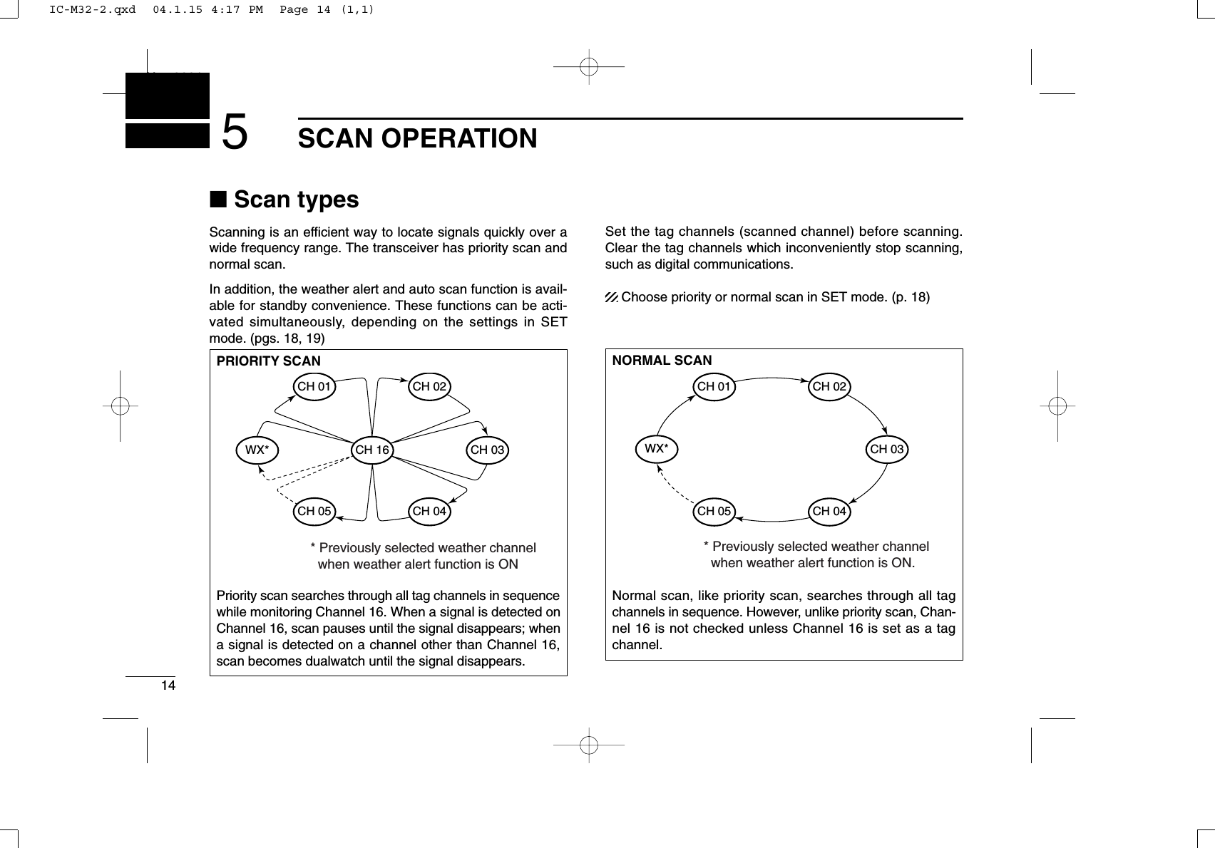
![155SCAN OPERATIONNew2001■Setting tag channelsFor more efficient scanning, add desired channels as tagchannels or clear the tag for unwanted channels. Non-tag channels will be skipped during scanning. Tag chan-nels can be assigned to each channel group (USA, INT, CAN)independently.qSelect the desired channel group (USA, INT, CAN) bypushing [CH/WX•U/I/C] for 1 sec., if desired.wSelect the desired channel to set as a tag channel.ePush both [Y] and [Z] for 1 sec. to set the displayed chan-nel as a tag channel.•“ ” appears in the function display.rTo cancel the tag channel setting, push both [Y] and [Z]for 1 sec.•“ ” disappears.✔Clearing all tag channels in the selected channel groupWhile pushing and holding both [Y] and [Z], turn power ONto clear all tag channels in the channel group.■Starting a scanSet the weather alert function, priority scan function, scan re-sume timer and auto scan function in advance, using SETmode. (pgs. 18, 19)qSelect the desired channel group (USA, CAN, INT) bypushing [CH/WX•U/I/C] for 1 sec., if desired.•When the weather alert function is in use, select the desiredweather channel with [CH/WX•U/I/C] and [Y]/[Z].wPush [SCN•DUAL] to start priority or normal scan.•“SCAN” blinks in the function display.•“16” appears on the sub channel readout during priority scan.•When a signal is received, scan pauses until the signal disap-pears or resumes after pausing 5 sec. according to scan resumetimer setting. (Channel 16 is still monitored during priority scan.)•Push [Y]/[Z] to check the scanning tag channels, change thescanning direction or resume the scan manually.eTo stop the scan, push [SCN•DUAL].•“SCAN” disappears.•Pushing [PTT], [16•9] or [CH/WX•U/I/C] also stops the scan.[Example]: Starting a normal scan.5Scan starts.DUAL DUALPush Pushto stop the scanReceiving a signal and audio is emitted.IC-M32-2.qxd 04.1.15 4:17 PM Page 15 (1,1)](https://usermanual.wiki/ICOM-orporated/269100.Manual-revised-in-response-to-FCC-correspondence-9722/User-Guide-389068-Page-21.png)
![16DUALWATCH/TRI-WATCHNew2001New20016■DescriptionDualwatch monitors Channel 16 while you are receiving another channel; tri-watch monitors Channel 16 and the callchannel while receiving another channel.■OperationqSelect the desired operating channel.wPush [SCN•DUAL] for 1 sec. to start dualwatch or tri-watch(depending on SET mode setting).•“DUAL” blinks during dualwatch; “TRI” blinks during tri-watch.•A beep tone sounds when a signal is received on Channel 16.•Tri-watch becomes dualwatch when receiving a signal on the callchannel.eTo cancel dualwatch/tri-watch, push [SCN•DUAL] again.DUALWATCH/TRI-WATCH SIMULATION•If a signal is received on Channel 16, dualwatch/tri-watchpauses on Channel 16 until the signal disappears.•If a signal is received on the call channel during tri-watch,tri-watch becomes dualwatch until the signal disappears.•To transmit on the selected channel during dualwatch/tri-watch, push and hold [PTT].Dualwatch Tri-watchCall channel[Example]: Operating tri-watch on INT channel 07.Tri-watch starts.Pushfor 1 sec.Signal is received on the call channel.Signal received on Channel 16 takes priority.Tri-watch resumes after the signal disappears.DUALIC-M32-2.qxd 04.1.15 4:17 PM Page 16 (1,1)](https://usermanual.wiki/ICOM-orporated/269100.Manual-revised-in-response-to-FCC-correspondence-9722/User-Guide-389068-Page-22.png)
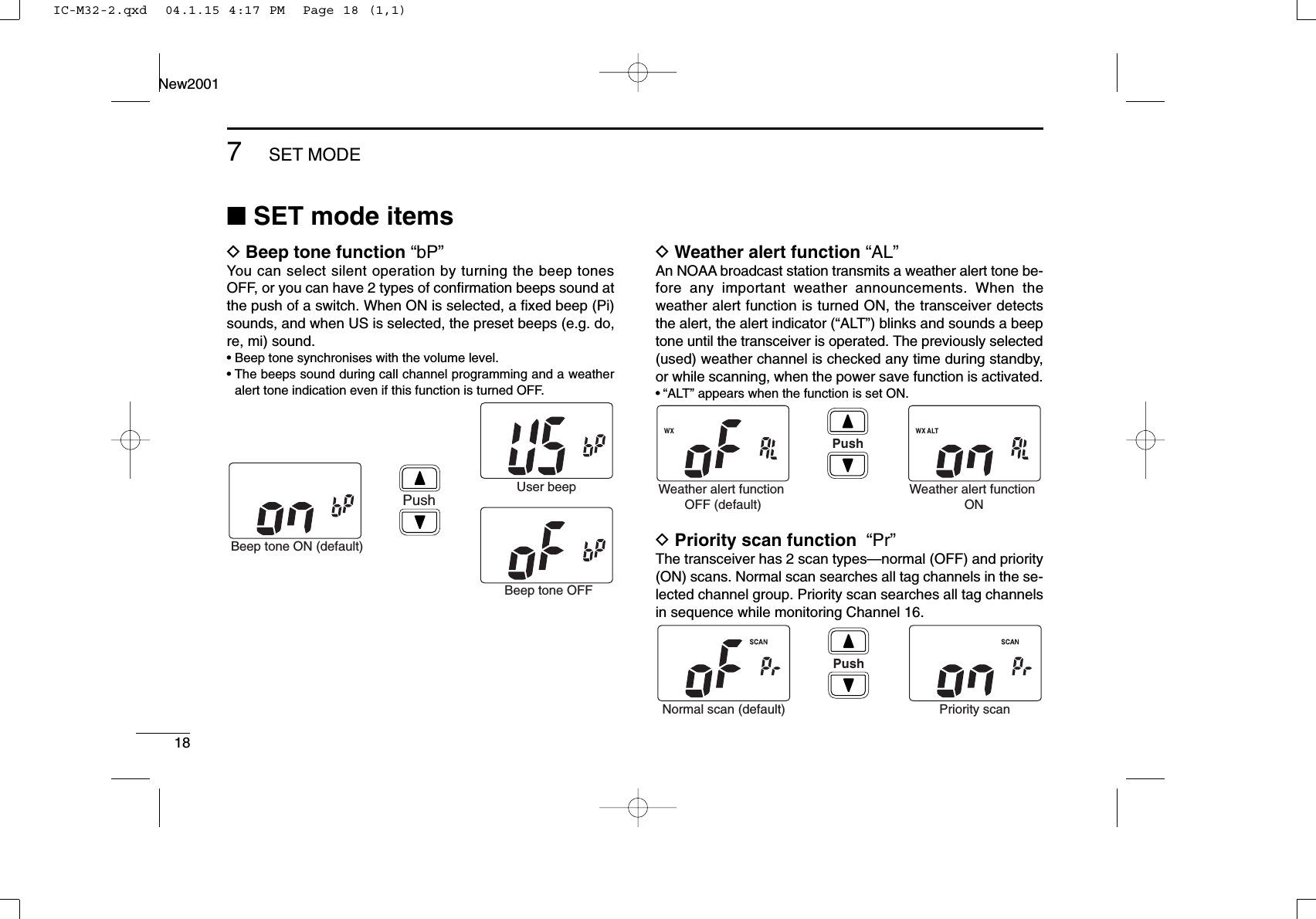
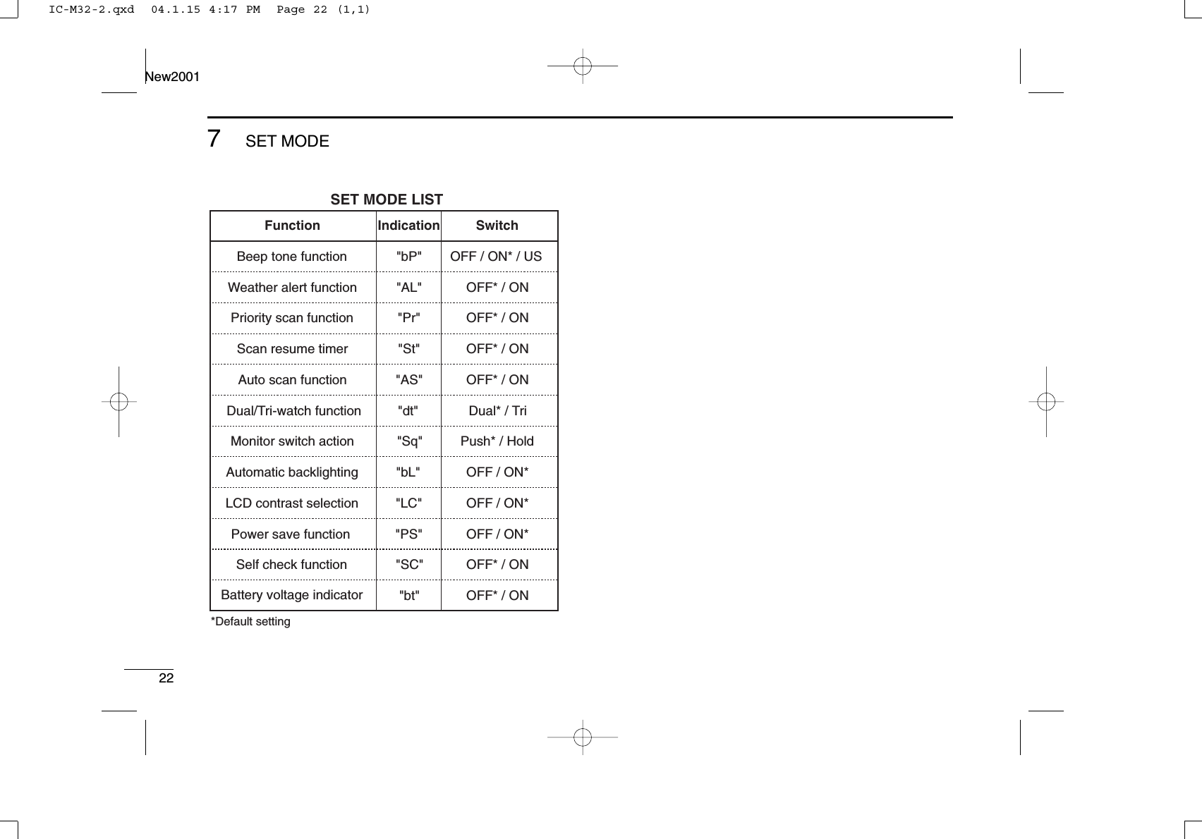
![177SET MODE67New2001■SET mode programmingSET mode is used to change the condition of 12 transceiverfunctions: beep tone function, weather alert function, priorityscan function, scan resume timer, auto scan function, dual/tri-watch function, monitor switch action, automatic backlighting,LCD contrast selection, auto power save function, self checkfunction and battery voltage indicator.DSET mode operationqTurn power OFF.wWhile pushing [SQL•MONI], turn power ON to enter SETmode.• “bp” appears.ePush [SQL•MONI] or [SQL•MONI] and [Y] to select the de-sired item, if necessary.rPush [Y]/[Z] to select the desired condition of the item.tTo exit SET mode, push [16•9].DSET MODE ITEMS The displays show the default settings, and the selected item is displayed in the dotted circle. Auto scanStarting item Beep tone Battery voltage Scan resume timer Dual/Tri-watch Automatic backlighting Power save LCD contrast Monitor switch Self check Priority scan Weather alertMONI: PushMONI: Push andIC-M32-2.qxd 04.1.15 4:17 PM Page 17 (1,1)](https://usermanual.wiki/ICOM-orporated/269100.Manual-revised-in-response-to-FCC-correspondence-9722/User-Guide-389068-Page-23.png)
![197SET MODENew20017DScan resume timer “St”The scan resume timer can be set as a pause (OFF) or timerscan (ON). When OFF is selected, the scan pauses until areceived signal disappears. When ON is selected, the scanpauses for 5 sec. after receiving a signal and then resumeseven if the signal has been received.DAuto scan function “AS”The Auto scan function starts the desired scan automaticallywhen no signal is received, and no operation is performed for30 sec.DDual/Tri-watch function “dt”This item selects dual or tri-watch as desired. See p. 16 fordetails.DMonitor switch action “Sq”The monitor switch action cuts off the squelch function tem-porarily. This switch action contains PUSH (Pu) or HOLD (Ho)settings as shown below.• Pu (PUSH): After pushing the [SQL•MONI] for 1 sec., the squelchopens and emits audio. The squelch is held open whilecontinuously pushing and holding [SQL•MONI]. (default)• Ho (HOLD): After pushing the [SQL•MONI] for 1 sec., the squelchopens and emits audio even [SQL•MONI] is released.To close the squelch, push any key.PushPush setting (default) Hold settingPushDualwatch function(default)Tri-watch functionPushAuto scan OFF (default) Auto scan ONPushScan resume timer OFF(default)Scan resume timer ONIC-M32-2.qxd 04.1.15 4:17 PM Page 19 (1,1)](https://usermanual.wiki/ICOM-orporated/269100.Manual-revised-in-response-to-FCC-correspondence-9722/User-Guide-389068-Page-25.png)
![207SET MODENew2001DAutomatic backlighting “bL”This function is convenient for nighttime operation. The auto-matic backlighting turns the backlighting ON when any keyexcept for [PTT] is pushed.• The backlighting is automatically turned OFF after 5 sec. of inactivity.DLCD contrast selection “LC”The contrast of the LCD can be turned ON (high contrast) andOFF (low contrast).DPower save function “PS”The power save function reduces current drain by deactivat-ing the receiver circuit for preset intervals. • ON : The power save function is turned ON. The power save func-tion will activate when no signal is received, and no operationis performed for 5 sec.• OFF: The power save function is turned OFF.PushPower save ON (default)Power save OFFPushLCD contrast ON (default)LCD contrast OFFPushAuto backlighting ON(default)Auto backlighting OFFIC-M32-2.qxd 04.1.15 4:17 PM Page 20 (1,1)](https://usermanual.wiki/ICOM-orporated/269100.Manual-revised-in-response-to-FCC-correspondence-9722/User-Guide-389068-Page-26.png)
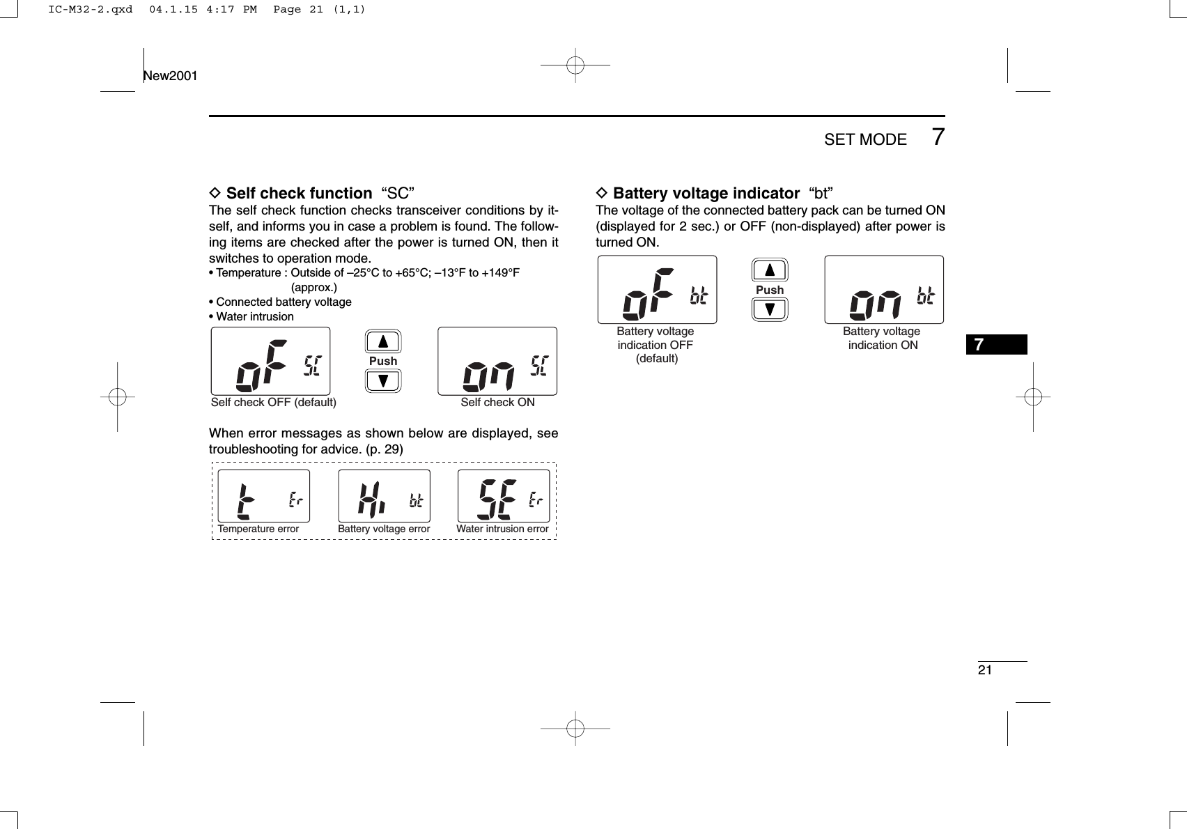
![2910TROUBLESHOOTING910PROBLEM POSSIBLE CAUSE SOLUTION REF.No sound from speaker. •Squelch level is too deep.•Volume level is too low.•Speaker has been exposed to water.p. 10p. 10—•Set squelch to the threshold point.•Push [+]/[–] to set a suitable level.•Drain water from the speaker.The transceiver doesnot turn ON.•The battery is exhausted.•Bad connection to the battery pack.p. 23p. 3•Recharge the battery pack.•Check the connection to the transceiver.Transmitting is impossi-ble, or high power cannot be selected.•Some channels are for low power or re-ceive only.•The battery is exhausted.•The battery over charged.•The output power is set to low.pgs. 8,9, 30p. 23—p. 11•Change channels.•Recharge the battery pack.•Verify the battery voltage is correct.•Push [H/L•LOCK] to select high power.The displayed channelcannot be changed.•Lock function is activated. •Push [H/L•LOCK] for 1 sec. to cancel thefunction.p. 13Scan does not start. •“TAG” channels are not programmed. •Set the desired channels as “TAG” channels. p. 15No beeps. •Beep tones are turned OFF. •Set the beep tones to ON (Fix Beep/UserBeep) in SET mode.p. 18Self check error.(Temperature)•The temperature is outside of –25°C to+65°C; –13°F to +149°F (approx)•Leave the transceiver at room temperaturefor a while. Turn the power ON to check if theinternal temperature has returned to normal.Self check error.(Battery voltage)•The connected battery pack’s voltage ismore than 11 V.•Verify the battery voltage is correct.——Self check error.(Water intrusion)•Water has entered the transceiver. •Have the transceiver checked at your localdistributor or dealer to see whether the trans-ceiver works properly or not.—IC-M32-2.qxd 04.1.15 4:17 PM Page 29 (1,1)](https://usermanual.wiki/ICOM-orporated/269100.Manual-revised-in-response-to-FCC-correspondence-9722/User-Guide-389068-Page-35.png)