ICOM orporated 270600 VHF Marine Transceiver User Manual IC M402A SA draft
ICOM Incorporated VHF Marine Transceiver IC M402A SA draft
UserManual.wiki
>
ICOM orporated
>
270600 User Manual
Manual
Navigation menu
Upload a User Manual
Namespaces
Wiki Guide
HTML
PDF
Info
Views
User Manual
Discussion / Help
Navigation
![iiIN CASE OF EMERGENCYIf your vessel requires assistance, contact other vessels andthe Coast Guard by sending a distress call on Channel 16.Or, transmit your distress call using digital selective calling onChannel 70.NOTEA WARNING STICKER is supplied with the transceiver.To comply with FCC regulations, this sticker must be affixed insuch a location as to be readily seen from the operating con-trols of the radio as in the diagram below. Make sure the cho-sen location is clean and dry before applying the sticker. (p. ?)EXAMPLEUSING DIGITAL SELECTIVE CALLING (Ch 70)DISTRESS CALL PROCEDURE1. While lifting up the key cover, push and hold[DISTRESS] for 5 sec. until you hear 5 short beepschange to one long beep.2. Wait for an acknowledgment on Channel 70 from acoast station.• After the acknowledgment is received, Channel 16 isautomatically selected.3. Push and hold [PTT], then transmit the appropriateinformation as listed above.USING CHANNEL 16DISTRESS CALL PROCEDURE1. “MAYDAY MAYDAY MAYDAY.”2. “THIS IS ...............” (name of vessel)3. Your call sign or other indication of the vessel (AND 9-digit DSC ID if you have one).4. “LOCATED AT ...............” (your position)5. The nature of the distress and assistance required.6. Any other information which might facilitate the rescue.New2001!IC-M402A_SA_draft.qxd 03.10.20 11:41 AM Page ii (1,1)](https://usermanual.wiki/ICOM-orporated/270600/User-Guide-376446-Page-3.png)
![2PANEL DESCRIPTIONNew20012■Front panelqDISTRESS KEY [DISTRESS]Transmits Distress call when pushed for 5 sec. (p. ?)wPOWER/VOLUME CONTROL [VOL]Turns power ON and OFF and adjusts the audio level. (p. 8)eSQUELCH CONTROL [SQL]Sets the squelch threshold level. (p. 8)rSCAN KEY [SCAN•TAG]➥Starts and stops Normal or Priority scan.➥Sets or clears the displayed channel as a tag (scanned)channel when pushed for 1 sec.➥While pushing [HI/LO] on the microphone, push for 3sec. to clear or set all tag channels in the selected chan-nel group.tCHANNEL/WEATHER CHANNEL KEY [CH/WX•DUAL]➥Toggles between regular channels and weather chan-nel when pushed momentarily. (p. 7)➥Starts Dualwatch or Tri-watch when pushed for 1 sec. (p. 11)➥Stops Dualwatch or Tri-watch when either is activated.yCHANNEL 16/CALL CHANNEL KEY [16•9]➥Selects Channel 16 when pushed. (p. 6)➥Selects call channel when pushed for 1 sec. (p. 6)•“CALL” appears when call channel is selected.➥Push for 3 sec. to enter call channel programming con-dition when call channel is selected. (p. 9)➥While pushing [CH/WX•DUAL], push to enter the chan-nel comments programming condition. (p. 10)➥Enters Set mode when pushed while turning power ON.(p. 14)Speaker Function display wqeiuytr IC-M402A!IC-M402A_SA_draft.qxd 03.10.20 11:41 AM Page 2 (1,1)](https://usermanual.wiki/ICOM-orporated/270600/User-Guide-376446-Page-8.png)
![32PANEL DESCRIPTIONNew2001uCHANNEL UP/DOWN KEYS [YY]/[ZZ]•[U/I/C]➥Selects the operating channels, Set mode settings, etc.(pgs. 6, 7, 14)➥While pushing [SCAN•TAG], push [Y]or [Z]to adjustthe brightness of the LCD and key backlight. (p. 10)➥Selects one of 3 regular channels in sequence whenboth keys are pushed. (p. 7)•International, U.S.A. and Canadian channels are available forregular channels.iDSC/INTERCOM KEY [DSC•IC]➥Selects the DSC menu when pushed. (p. ?)➥Activates an optional intercom function when pushed for1 sec. (p. ?, IC-M402A only)➥Shows current position and time from a GPS receiver,when pushed for 1 sec. (p. ?)2!IC-M402A_SA_draft.qxd 03.10.20 11:41 AM Page 3 (1,1)](https://usermanual.wiki/ICOM-orporated/270600/User-Guide-376446-Page-9.png)
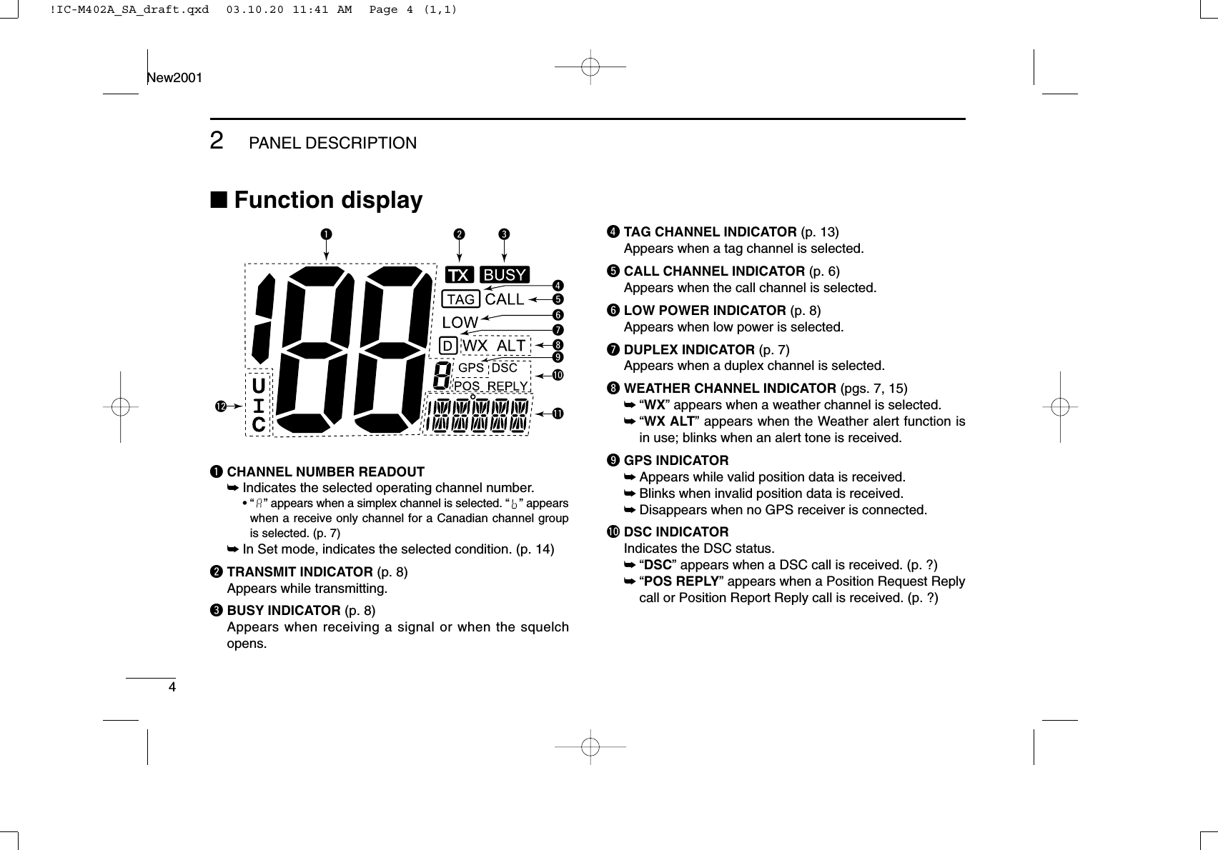
![52PANEL DESCRIPTIONNew2001!1 CHANNEL COMMENT INDICATOR➥Channel comment appears if programmed. (p. 10)➥“” scrolls when the battery voltage drops toapprox. 10 V DC or below.➥“” blinks during Dualwatch; “” blinks during Tri-watch. (p. 11)!2 CHANNEL GROUP INDICATOR (p. 7)Indicates whether a U.S.A. “U,” International “I” or Cana-dian “C” channel is in use.■MicrophoneqPTT SWITCH [PTT]Push and hold to transmit; release to receive. (p. 8)wCHANNEL UP/DOWN KEYS [YY]/[ZZ]Push either key to change the operating memory channel,Set mode settings, etc. (pgs. 6, 7, 14)eTRANSMIT POWER KEY [HI/LO]➥Toggles power high and lower when pushed. (p. 8)•Some channels are set to low power only.➥While pushing [HI/LO], turn power ON to toggle the mi-crophone lock function ON and OFF. (p. 10)Microphonewqe2!IC-M402A_SA_draft.qxd 03.10.20 11:41 AM Page 5 (1,1)](https://usermanual.wiki/ICOM-orporated/270600/User-Guide-376446-Page-11.png)
![6BASIC OPERATIONNew20013■Channel selectionïïChannel 16Channel 16 is the distress and safety channel. It is used forestablishing initial contact with another station and for emer-gency communications. Channel 16 is monitored during bothDualwatch and Tri-watch. While standing by, you must moni-tor Channel 16.➥Push [16•9]momentarily to select Channel 16.➥Push [CH/WX•DUAL]to return to the condition before select-ing Channel 16, or push [Y]or [Z]to select operating chan-nel.ïïChannel 9 (Call channel)Each regular channel group has a separate leisure-use callchannel. The call channel is monitored during Tri-watch. Thecall channels can be programmed (p. 9) and are used to storeyour most often used channels in each channel group forquick recall.➥Push [16•9]for 1 sec. to select the call channel of the se-lected channel group.•“CALL” and call channel number appear.•Each channel group may have an independent call channel afterprogramming a call channel. (p. 9)➥Push [CH/WX•DUAL]to return to the condition before se-lecting call channel, or push [Y]or [Z]to select an oper-ating channel.Pushfor 1 sec.Push!IC-M402A_SA_draft.qxd 03.10.20 11:41 AM Page 6 (1,1)](https://usermanual.wiki/ICOM-orporated/270600/User-Guide-376446-Page-12.png)
![73BASIC OPERATIONNew2001ïïU.S.A.,Canadian and international channelsThere are 57 U.S.A., 61 Canadian and 57 international chan-nels. These channel groups may be specified for the operat-ing area.qPush [CH/WX•DUAL]to select a regular channel.•If a weather channel appears, push [CH/WX•DUAL]again.wPush both [Y]and [Z]on the transceiver to change thechannel group, if necessary.•U.S.A., International and Canadian channels can be selected insequence.ePush [Y]or [Z]to select a channel.•“DUP” appears for duplex channels.•“ ” appears when a simplex channel is selected. “” appearswhen a receive only channel for a Canadian channel group isselected.ïïWeather channelsThere are 10 weather channels. These are used for monitor-ing broadcasts from NOAA (National Oceanographic and At-mospheric Administration.)The transceiver can detect a weather alert tone on the se-lected weather channel while receiving the channel, duringstandby on a regular channel or while scanning. (p. 15)qPush [CH/WX•DUAL]once or twice to select a weatherchannel.•“WX” appears when a weather channel is selected.• “WX ALT” appears when the Weather alert function is in use.(p. 15)wPush [Y]or [Z]to select a channel.Push once or twiceWhen Weather alert is OFF. When Weather alert is ON.Push and3!IC-M402A_SA_draft.qxd 03.10.20 11:41 AM Page 7 (1,1)](https://usermanual.wiki/ICOM-orporated/270600/User-Guide-376446-Page-13.png)
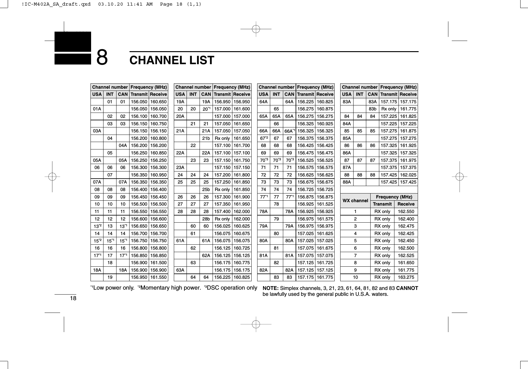
![83BASIC OPERATIONNew2001■Receiving and transmittingCAUTION: Transmitting without an antenna may dam-age the transceiver.qRotate [VOL] to turn power ON.wSet the audio and squelch levels.➥Rotate [SQL] fully counterclockwise in advance.➥Rotate [VOL] to adjust the audio output level.➥Rotate [SQL] clockwise until the noise disappears.eTo change the channel group, push both [Y]and [Z]onthe transceiver. (p. 7)rPush [Y]or [Z]to select the desired channel. (p. 6)•When receiving a signal, “” appears and audio is emittedfrom the speaker.•Further adjustment of [VOL] may be necessary.tPush [HI/LO] on the microphone to select the outputpower if necessary.•“LOW” appears when low power is selected.•Choose low power for short range communications, choose highpower for longer distance communications.•Some channels are for low power only.yPush and hold [PTT] to transmit, then speak into the mi-crophone (M).•“ ” appears.•Channel 70 cannot be used for transmission other than DSC.uRelease [PTT] to receive.Simplex channels, 3, 21, 23, 61, 64, 81, 82 and 83 CAN-NOT be lawfully used by the general public in U.S.A. wa-ters.IMPORTANT: To maximize the readability of your trans-mitted signal, pause a few sec. after pushing [PTT], holdthe microphone 2 to 4 inches (5 to 10 cm) from your mouthand speak into the microphone (M) at a normal voice level.urtMyqM: Microphonewre!IC-M402A_SA_draft.qxd 03.10.20 11:41 AM Page 8 (1,1)](https://usermanual.wiki/ICOM-orporated/270600/User-Guide-376446-Page-14.png)
![93BASIC OPERATIONNew2001■Call channel programmingCall channel is used to select Channel 9 (default), however,you can program the call channel with your most often-usedchannels in each channel group for quick recall.qPush both [Y]and [Z]on the transceiver one ormore times to select thedesired channel group(U.S.A., International orCanada) to be pro-grammed.wPush [16•9]for 1 sec. toselect the call channel ofthe selected channelgroup.•“CALL” and call channelnumber appear.ePush [16•9]again for 3sec. (until a long beepchanges to 2 short beeps)to enter call channel pro-gramming condition.•Channel number startsblinking.rPush [Y]or [Z]to selectthe desired channel.tPush [16•9]to programthe displayed channel asthe call channel.•Push [CH/WX•DUAL]tocancel.•The channel number stopsblinking.3!IC-M402A_SA_draft.qxd 03.10.20 11:41 AM Page 9 (1,1)](https://usermanual.wiki/ICOM-orporated/270600/User-Guide-376446-Page-15.png)
![103BASIC OPERATIONNew2001■Channel commentsMemory channels can be labeled with alphanumeric com-ments of up to 10 characters each.More than 6 characters comment scrolls automatically at thechannel comment indicator after the channel selection.Capital letters, small letters (except f, j, p, s, y, x, z), 0 to 9,some symbols (= ✱+ – . /) and space can be used.qSelect the desired channel.•Cancel Dualwatch, Tri-watch or Scan in advance.wWhile pushing [CH/WX•DUAL], push [16•9]to editthe channel comment.•A cursor and the first char-acter start blinking alter-nately.eSelect the desired charac-ter by pushing [Y]or [Z].• Push [SCAN•TAG]or [CH/WX•DUAL]to move the cursor forwardor backward, respectively.rRepeat step eto input all characters.tPush [16•9]to input and set the comment.•Push [DSC•IC]to cancel.•A cursor and the character stop blinking.yRepeat steps qto tto program other channel com-ments, if desired.■Microphone lock functionThe microphone lock function electrically locks [Y]/[Z]and[HI/LO] keys on the supplied microphone. This prevents ac-cidental channel changes and function access.➥While pushing [HI/LO] on the microphone, turn power ONto toggle the lock function ON and OFF.■Display backlightingThe function display and keys can be backlit for better visibil-ity under low light conditions.➥While pushing [SCAN•TAG], push [Y]or [Z]to adjust thebrightness of the LCD and key backlight.•The backlight is selectable in 3 levels and OFF.[HI/LO][Y]/[Z]!IC-M402A_SA_draft.qxd 03.10.20 11:41 AM Page 10 (1,1)](https://usermanual.wiki/ICOM-orporated/270600/User-Guide-376446-Page-16.png)
![114DUALWATCH/TRI-WATCH■DescriptionDualwatch monitors Channel 16 while you are receiving another channel; Tri-watch monitors Channel 16 and the callchannel while receiving another channel.■OperationqSelect Dualwatch or Tri-watch in Set mode. (p. 15)wSelect the desired operating channel.ePush [SCN•DUAL]for 1 sec. to start Dualwatch or Tri-watch.•“ ” blinks during Dualwatch; “” blinks during Tri-watch.•A beep tone sounds when a signal is received on Channel 16.rTo cancel Dualwatch/Tri-watch, push [SCN•DUAL]again.DUALWATCH/TRI-WATCH SIMULATION•If a signal is received on Channel 16, Dualwatch/Tri-watchpauses on Channel 16 until the signal disappears.•If a signal is received on the call channel during Tri-watch,Tri-watch becomes Dualwatch until the signal disappears.•To transmit on the selected channel during Dualwatch/Tri-watch, push and hold [PTT].Dualwatch Tri-watchCall channel[Example]: Operating Tri-watch on INT Channel 25Tri-watch starts.Signal is received on call channel.Signal is received on Channel 16 takes priority.Tri-watch resumes after the signal disappears.Pushfor 1 sec.34!IC-M402A_SA_draft.qxd 03.10.20 11:41 AM Page 11 (1,1)](https://usermanual.wiki/ICOM-orporated/270600/User-Guide-376446-Page-17.png)
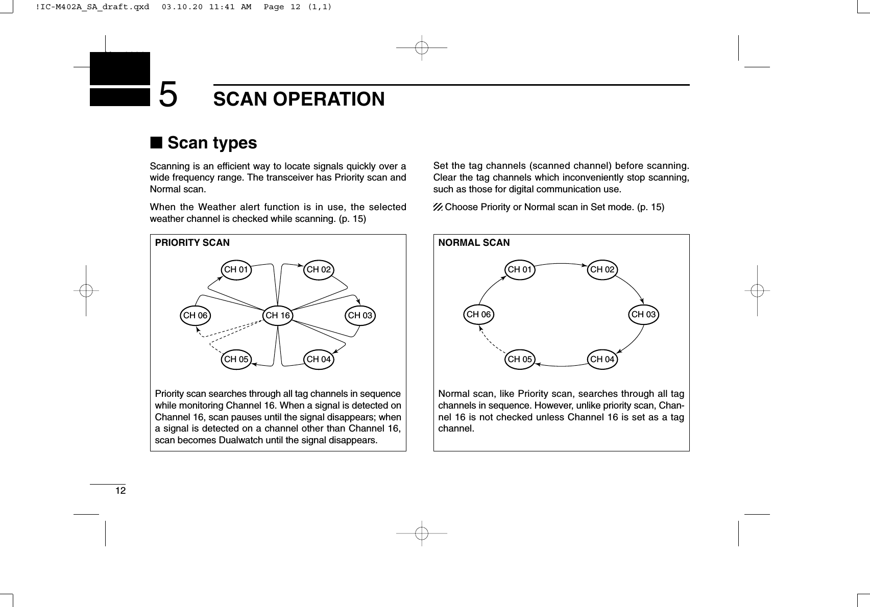
![135SCAN OPERATIONNew2001■Setting tag channelsFor more efficient scanning, add desired channels as tagchannels or clear the tag for unwanted channels. Channels are not tagged will be skipped during scanning. Tagchannels can be assigned to each channel group (USA, INT,CAN) independently.qSelect the desired channel group (USA, INT, CAN) bypushing both [Y]and [Z].wSelect the desired channel to set as a tag channel.ePush [SCAN•TAG]for 1 sec. to be set the displayed chan-nel as a tag channel.•“ ” appears in the display.rTo cancel the tag channel setting, push [SCAN•TAG]for 1sec.•“ ” disappears.✔Clearing (or setting) all tagged channelsWhile pushing [HI/LO] on the microphone, push [SCAN•TAG]for 3 sec. (until a long beep changes to 2 short beeps) to clearall tag channels in the channel group.• Repeat above procedure to set all tag channels.■Starting a scanSet scan type (Priority or Normal) and scan resume timer inadvance, using Set mode. (p. 15)qSet tag channels as described at left.wMake sure the squelch is closed to start a scan.eSelect the channel group (USA, CAN, INT) by pushingboth [Y]and [Z]on the transceiver, if desired.rPush [SCAN•TAG]to start Priority or Normal scan.•“ ” or “” appears at the channel comment indicator.•When a signal is detected, scan pauses until the signal disap-pears or resumes after pausing 5 sec. according to Set modesetting. (Channel 16 is still monitored during Priority scan.)•Push [Y]or [Z]to check the scanning tag channels, to changethe scanning direction or resume the scan manually.•“ ” blinks at the channel comment indicator and a beep tonesounds when a signal is received on Channel 16 during Priorityscan.tTo stop the scan, push [SCAN•TAG].Scan starts. When a signal is received.[Example]: Starting a normal scan.Push5!IC-M402A_SA_draft.qxd 03.10.20 11:41 AM Page 13 (1,1)](https://usermanual.wiki/ICOM-orporated/270600/User-Guide-376446-Page-19.png)
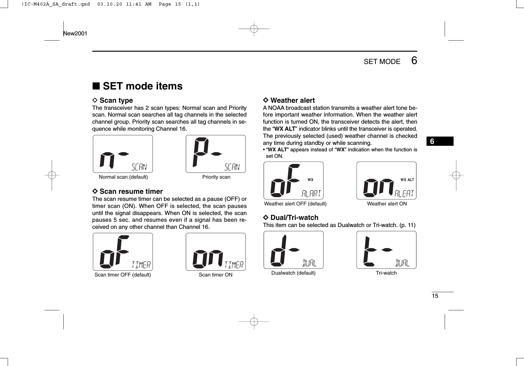
![14SET MODENew20016■Set mode programmingSet mode is used to change the conditions of the trans-ceiver’s functions: scan type (Normal or Priority,) scan re-sume timer, Weather alert, Dual/Tri-watch, DSC watch, trans-ceiver’s beep tone, LCD contrast and Auto ACK.Available functions may differ depending on dealer setting.DSet mode operationqTurn power OFF.wWhile pushing [16•9], turn power ON to enter Set mode.• “” appears on channel comment indicator.eAfter the display appears, release [16•9].rPush [16•9]to select the desired item, if necessary.tPush [Y]or [Z]to select the desired condition of the item.yTurn power OFF, then ON again to exit Set mode.DSET MODE CONSTRUCTION Beep tone LCD contrastStarting item Scan mode Scan resume timer Weather alert Dual/tri watch DSC watch Auto acknowledgementScrollsPushScrolls!IC-M402A_SA_draft.qxd 03.10.20 11:41 AM Page 14 (1,1)](https://usermanual.wiki/ICOM-orporated/270600/User-Guide-376446-Page-20.png)
![177TROUBLESHOOTING67PROBLEM POSSIBLE CAUSE SOLUTION REF.No sound from speaker. •Squelch level is too high.•Volume level is too low.•Speaker has been exposed to water.p. 8p. 8—•Set squelch to the threshold point.•Set [VOL] to a suitable level.•Drain water from the speaker.The transceiver doesnot turn ON.•Bad connection to the power supply. p. ?•Check the connection to the transceiver.Transmitting is impossi-ble, or high power cannot be selected.•Some channels are for low power or re-ceive only.•The output power is set to low.pgs. 6,7, 18p. 8•Change channels.•Push [HI/LO] on the microphone to selecthigh power.Scan does not start. •“TAG” channel is not programmed. •Set the desired channels as “TAG” channels. p. 13No beeps. •Beep tones are turned OFF.•The squelch is open.•Turn the beep tone ON in Set mode.•Set squelch to the threshold point.p. 16p. 8Distress call cannot betransmitted.•MMSI (DSC self ID) code is not pro-grammed.•Program the MMSI (DSC self ID) code. p. ?!IC-M402A_SA_draft.qxd 03.10.20 11:41 AM Page 17 (1,1)](https://usermanual.wiki/ICOM-orporated/270600/User-Guide-376446-Page-23.png)