ICOM orporated 271400 Marine Radar User Manual MR 1000T2 R2 Instruction Manual
ICOM Incorporated Marine Radar MR 1000T2 R2 Instruction Manual
UserManual.wiki
>
ICOM orporated
>
271400 User Manual
>
Manual
Contents
1.
Manual
2.
User Manual
Manual
Navigation menu
Upload a User Manual
Namespaces
Wiki Guide
HTML
PDF
Info
Views
User Manual
Discussion / Help
Navigation
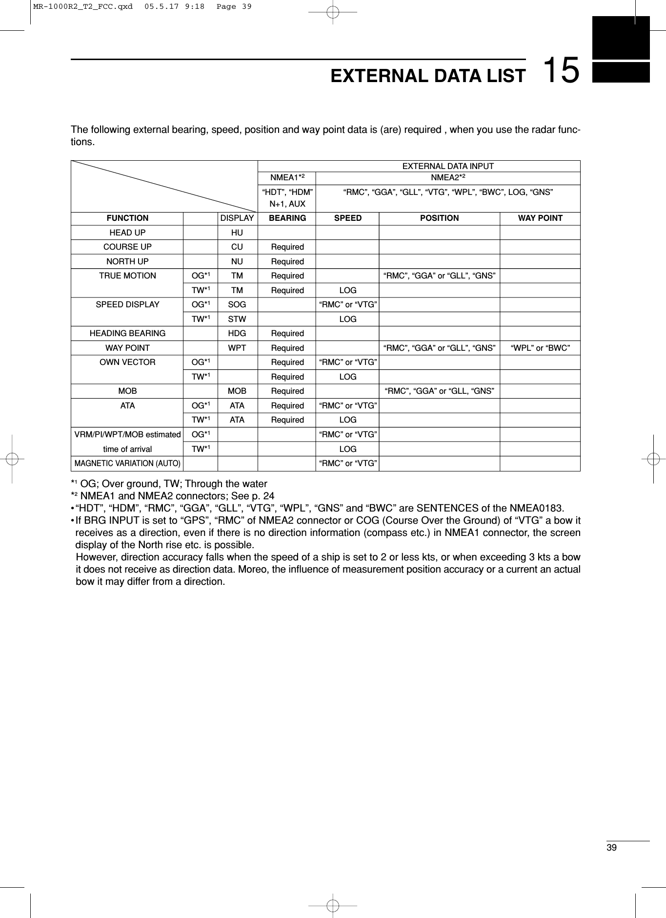
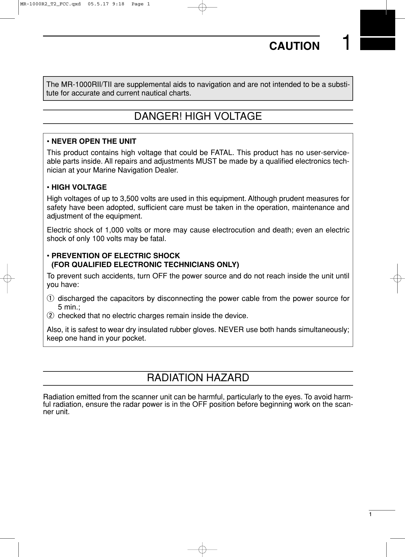
![iiFOREWORDThank you for purchasing Icom’s MR-1000RII/TII MA-RINE RADAR. The radar is designed especially for fishing boats. Ithas powerful transmission power, 10 inch CRT displayand many other advanced features. If you have any questions regarding the operation ofthe radar, contact your nearest authorized Icom Inc.dealer.IMPORTANTREAD ALL INSTRUCTIONS carefully and com-pletely before attempting to operate the marine radar.SAVE THIS INSTRUCTION MANUAL. Thismanual contains important safety and operating in-structions for the MR-1000RII/TII.EXPLICIT DEFINITIONSThe following explicit definitions apply to this instruc-tion manual. PRECAUTIONRNEVER let metal, wire or other objects touch anyinternal part of the radar.RNEVER place the radar within the reach of chil-dren.RNEVER expose the display unit to rain, salt wateror any other liquids.NEVER connect the radar to AC or more than 42 VDC. This will damage the radar.AVOID using the radar near any magnetic materials,such as a loudspeaker or a large power transformer,as this can cause distortion of the CRT display. AVOID placing the display unit in excessively dusty en-vironments.AVOID placing the display unit near heating equipmentor in direct sunlight or where hot or cold air blows di-rectly onto it.AVOID using the scanner unit in areas where the tem-perature is below –25˚C (–13˚F) or above +70˚C(+158˚F). AVOID using the display unit in areas wherethe temperature is below –15˚C (+5˚F) or above +55˚C(+131˚F).AVOID using strong solvents such as benzene or al-cohol for cleaning the radar, as they may damage thesurfaces. BE CAREFUL!SART signal may not be detected and maynot be displayed on the screen dependingon the SEA, RAIN or IR settings.Follow the settings as below to detect theSART signal on the screen.qSelect the screen range between 6 NMto 12 NM with [+/–]. (p. 2)wSet the [GAIN] as high as possible. (p. 3)eSet the [SEA] to minimum. (p. 3)rSet the [RAIN] to minimum. (p. 3)tTurn the [IR] OFF.yTurn the [STRETCH] OFF.WORDR WARNINGCAUTIONNOTEDEFINITIONPersonal injury, fire hazard or electric shock may occur.Equipment damage may occur.If disregarded, inconvenience only. No risk of personal injury, fire or electric shock.MR-1000R2_T2_FCC.qxd 05.5.17 9:18 Page 3](https://usermanual.wiki/ICOM-orporated/271400.Manual/User-Guide-581274-Page-3.png)
![2PANEL DESCRIPTION2■Front panelqPOWER SWITCH [POWER] (p. 8)Turns power ON and OFF.•The standby screen appears for 90 sec. while warmingup the magnetron. • The initial screen appears with a beep after the powerhas been turned ON.wTRANSMIT/SAVE SWITCH [TX (SAVE)]➥Push to toggle between the TX mode and thestandby mode. (p. 9)➥Push and hold for 1 sec. to turn the power savefunction ON. The radar for TX interval scan isfixed at 10 revolutions. (p. 12)•Select the save time in INT. SETTING menu.eRANGE UP/ DOWN SWITCHES [+]/[–] (p. 9)Push [+] to increase the screen range. Push [–] to decrease the screen range.rUP, DOWN, LEFT, RIGHT KEYS [ÙÙ ÚÚ ΩΩ≈≈]]Set the EBLs, VRMs, alarm area, ATA target, etc.according to the key pushed.Use the [ÙÙ] [ÚÚ] to select menu item and [ΩΩ] [≈≈] toset the item.Using the [ÙÙ ΩΩ]/[ÙÙ ≈≈] or [ÚÚ ΩΩ]/[ÚÚ ≈≈] combinationallows you to move the cross line cursor to theupper (or lower) left or right.tTRAILS SWITCH [TRAILS] (p. 12)Push to toggle the trail function ON and OFF. This isuseful for watching other ship’s tracks, approx. rela-tive speed etc.•Trail Time can be set in VIDEO menu.yZOOM FUNCTION [ZOOM] (p. 11)Push [TARGET] and [TRAILS] simultaneously totoggle the ZOOM function ON and OFF. ZOOMfunction expands the target to 2 times normal.•Move the cursor to the target, then turn the function ON.•The screen zooms around the middle of the cursor andown ship.•This function is not available on 1⁄8and 32 NM or aboveranges.uMODE SWITCH [MODE]Push to select one of Head-up (H UP), Course-up(C UP), North-up (N UP) or True motion (TM)screens. •The North-up and Course-up screens can be selectedonly when a bearing data format is connected. (p. 39)•TM screen requires bearing data and LOG or positiondata. (p. 39)•TM screen is not available at 32 NM or above range.iOFF CENTER FUNCTION [OFF CENT] (p. 10)Push [ALM] and [MODE] simultaneously to turn theOFF CENTER function ON or OFF. •This function is available for 24NM or shorter range se-lection.MOBGAINSEARAINPOWERTXSAVETARGETTRAILSZOOMALMMODEOFF CENTEBL1VRM1PIBRILL MENUHL OFFEBL2VRM2MARINE RADAR TXSAVETARGET TRAILSMODEALM+-MOBMENUEBL2VRM2EBL1VRM1BRILLZOOMOFF CENTPIHL OFFGAINSEARAINPOWERerqwtuo!1yi!2!3!4!5!6!7!8!9@0!0Control panelMR-1000R2_T2_FCC.qxd 05.5.17 9:18 Page 2](https://usermanual.wiki/ICOM-orporated/271400.Manual/User-Guide-581274-Page-6.png)
![32PANEL DESCRIPTIONoEBL2 (VRM2) SWITCH [EBL2 (VRM2)] (pgs. 15–16)Push to display the electronic bearing line 2 (EBL2)and the variable range marker 2 (VRM2), and acti-vate the [Ω≈]for the electronic bearing line selec-tor and [Ù Ú] for the range marker selector.•When the VRM1 and EBL1 ($9 %2) are displayed, thecenter of VRM2 appears at the intersection point of theVRM1 and EBL1. !0 PARALLEL INDEX LINE FUNCTION [PI]Push [EBL1] and [EBL2] simultaneously to togglethe parallel index line ON and OFF.•Push [Ω≈] keys to rotate the lines, and push [Ù Ú]keys to adjust the line spaces.!1 MENU SWITCH [MENU] (pgs. 6–7)Push [MENU] to toggle the VIDEO, FUNCTION,ATA, INT. SETTING and SERVICE MAN menu.Push [Ù Ú] keys to select the items and push [Ω≈] keys to change the setting.!2 HEADING LINE OFF FUNCTION [HL OFF] (p. 9)Push [BRILL] and [MENU] simultaneously to turnoff the heading line temporarily.!3 GAIN CONTROL [GAIN] (p. 9)Adjusts the receiver amplifier gain.•Clockwise rotation increases the gain•Increased gain may increase screen noise.!4 SEA CLUTTER CONTROL [SEA] (p. 10)This function serves to eliminate echoes from thewaves at close range.Reduces the receiver gain for close objects withina radius of 8 nautical miles (approx.) to eliminatesea clutter. Rotate the control fully clockwise to activate the au-tomatic SEA control function. SEA indicator (@6) ap-pears in the upper left of the screen.•Under normal conditions set the SEA to a minimum.•Use this control with caution when the sea is rough. !5 RAIN CLUTTER CONTROL [RAIN] (p. 10) This function eliminates reflection echoes from rain,snow, fog, etc.Rotate the control fully counter clockwise to deacti-vate the RAIN function. RAIN indicator (@8) disappears.!6 MAN OVERBOARD [MOB] Push to mark the man overboard point on thescreen. When a crew member falls overboard, push[MOB] for 1 sec. to display the MOB symbol ( ) onthe screen.•MOB readout shows the bearing, distance and esti-mated time to the MOB point with current speed.•Push [MOB] for 1 sec. to cancel the function.•Position and bearing data are necessary.!7 TARGET SWITCH [ATA] (pgs. 18–20)A setup of target caught by ATA (up to 10 targetscan be set).•Push [Ù Ú Ω ≈] to move the cross cursor on the echowhich you want to plot on the screen before turning thefunction ON.•Select “ATA” function ON in the “ATA” menu, set the ap-propriate No. DISP, VECT, OWN VECT, ALARM, CPALIMIT and TCPA LIMIT setting.!8 ALARM SWITCH [ALM] (p. 17)Push [ALM] to toggle the alarm function ON andOFF.Push and hold [ALM] for 1 sec. to enter the alarmarea setting condition.•Push [Ù Ú Ω ≈] to move the cross cursor to the zonestarting point, then push [ALM] for 1 sec. The startingring of the zone is created. Then push [Ù Ú Ω ≈] to fixthe finish point, the desired alarm zone will automaticallyform.!9EBL1 (VRM1) SWITCH [EBL1 (VRM1)] (pgs. 15–16)Push to display the electronic bearing line 1 (EBL1)and the variable range marker 1 (VRM1) and acti-vate the [Ω≈] for the electronic bearing line selec-tor, and [ÙÚ] for the range marker selector.•EBL1 bearing and VRM1 distance are displayed, in thebottom window.•When EBL1 and VRM1 are displayed, the beginning ofEBL2 appears at the intersection point of EBL1 andVRM1. @0 DISPLAY BRILLIANCE SWITCH [BRILL] (p. 9)➥Push to increase or decrease the brilliance of thepicture on the display.➥Push for 1 sec. to select the maximum brilliance.•The brightness of the symbol, character and illumi-nation can be adjusted in the “SYMBOL”, “CHAR-ACTER” and “KEY ILLUM” of the INT. SETTINGmenu independently.MR-1000R2_T2_FCC.qxd 05.5.17 9:18 Page 3](https://usermanual.wiki/ICOM-orporated/271400.Manual/User-Guide-581274-Page-7.png)
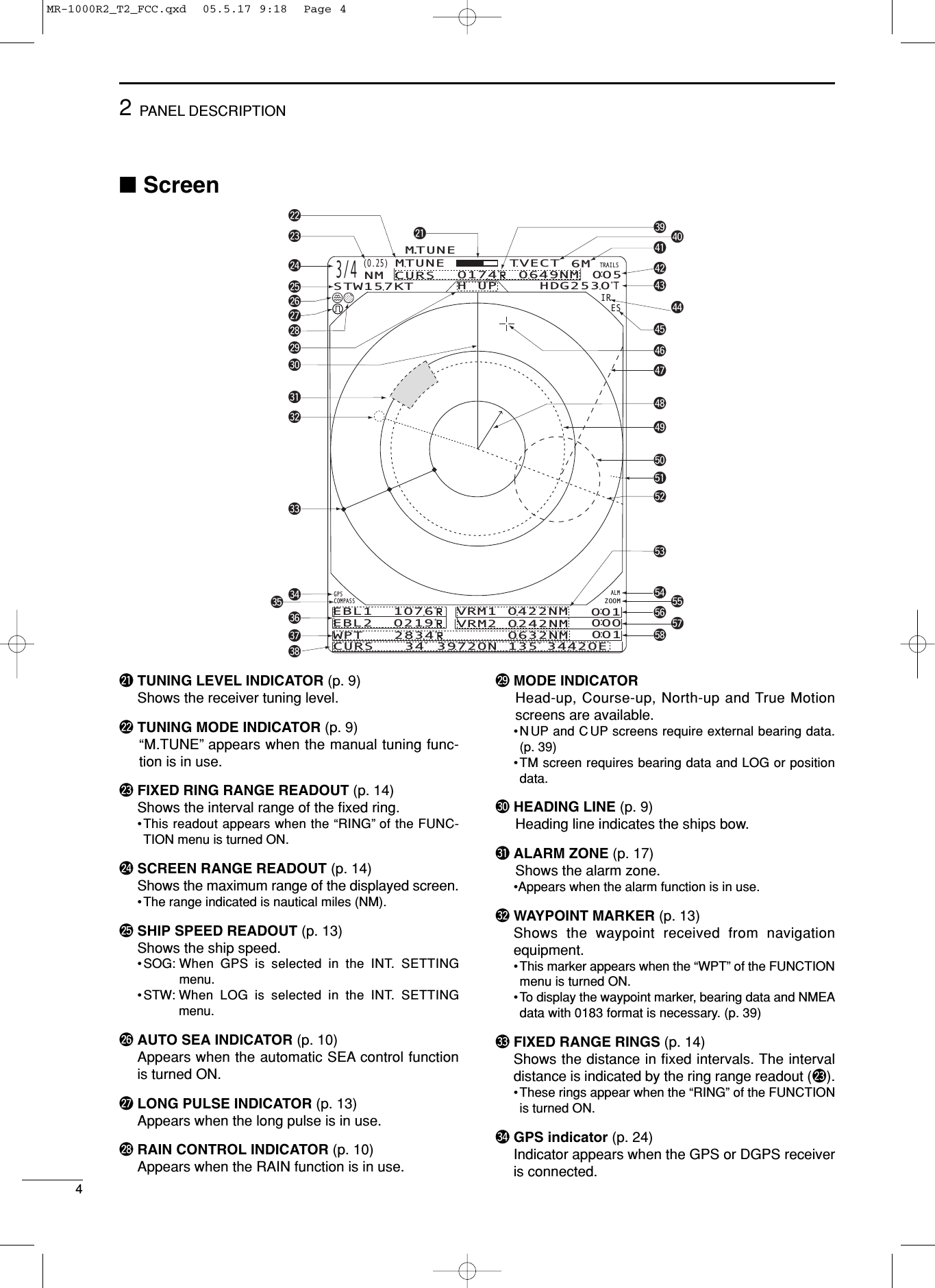
![52PANEL DESCRIPTION#5 COMPASS INDICATOR (pgs. 24, 39)•GYRO : NMEA (gyro) is connected.•COMPASS : NMEA (compass), N+1 or AUX data isconnected.#6 EBL1/ 2 READOUTS (pgs. 15–16)Shows the bearing of the displayed Electronic Bear-ing Lines (EBL1 and EBL2) when the EBL is in use.•EBL2 shows PI (!0) readout.#7 WAYPOINT/MOB READOUTS (p. 13)➥Shows the bearing and distance to the waypointreceived from navigation equipment.•This readout appears when the “WPT” of the FUNC-TION menu is turned ON. •To display the waypoint/MOB marker, bearing dataand NMEA data with 0183 format is necessary.(p. 39)➥Shows the bearing and distance to the MOB(Man Over Board) event marker.•Push [MOB] to cancel the readout and the symbol. #8 POSITION/CURSOR READOUT (p. 13)Shows your own ship or cursor latitude and longi-tude readout when external NMEA data with 0183format is connected.•Select ‘SHIP’or ‘CURS’in the “POSN DISP” of theFUNCTION menu.•To display the POSITION; NMEA 0183 is necessary.•To display the CURSOR; NMEA 0183 and bearing dataare necessary. #9 CURSOR INDICATOR Shows the bearing and distance to the cursor. $0 VECTOR INDICATOR (p. 18)Shows the ATA and OWN vector type. •T: True vector•R: Relative vector$1 VECTOR TIME INDICATOR (p. 18)Shows the vector interval time. Select vector timein the “TRAIL TIME” of the VIDEO menu.•30 min. is applied, when ‘∞’is selected for the vectortime.$2 TRAILS INDICATOR (p. 12) Shows the trail time.•Echo remains with gradation during the trail time periodon the screen. (Except for the trail time; ∞)•Progressing time counter starts to count the time untilthe timer reaches the trail time.$3 HEADING INDICATOR Shows the heading bearing readout.•The HDG readout indicates the bow of the ship’s bearingin a clockwise direction from north.$4 IR INDICATOR (p. 11)Eliminates or reduces interference caused by otherradar operating nearby.•This function is available when the “IR” in the VIDEOmenu is set to 1 or 2. $5 ECHO STRETCH INDICATOR (p. 6) Appears when the echo stretch function is in use.•This function is available when the “STRETCH” of theVIDEO menu is turned ON. $6 CROSS LINE CURSOR Used for measuring the bearing and distance, set-ting the alarm zone, selecting the ATA targets, etc. • Push [Ù Ú Ω ≈] several times to move the cursor.$7 EBL2 (pgs. 15–16)Used for bearing measurement. When a target isselected, the EBL readout (#6) shows the bearing.$8 OWN SHIP VECTOR INDICATORShows the vector of your own ship.$9 VRM 1 (pgs. 15–16)%0 VRM 2 (pgs. 15–16)Used for distance measurement. When a target isselected, the VRM1/2 readout (%3) shows the dis-tance.%1 NORTH MARK The north mark shows the true north direction.%2 EBL1 (pgs. 15–16)Used for bearing measurement. When a target isselected, the EBL readout (#6) shows the bearing.%3 VRM1/2 READOUTS (pgs. 15–16)Shows the distance of the displayed Variable RangeMarkers (VRM1 and VRM2) when the VRM is inuse.•Nautical miles (NM) and kilometers (KM) can be se-lected in the FUNCTION menu as the distance unit. %4 ALARM INDICATOR (p. 17)Appears when the alarm function is in use. %5 ZOOM INDICATOR (p. 11)Appears when the zoom function is in use.•Push [TARGET] and [TRAILS] simultaneously to turnthe function ON or OFF.%6 TIME INDICATOR%7 TIME INDICATORShows the estimated time to the marker edge fromcenter of the marker with current speed.%8 TIME INDICATOR Shows the estimated time to the waypoint with cur-rent speed.MR-1000R2_T2_FCC.qxd 05.5.17 9:18 Page 5](https://usermanual.wiki/ICOM-orporated/271400.Manual/User-Guide-581274-Page-9.png)
![36MENU■VIDEODTUNE•AUTO : Automatic tuning.•“A.TUNE” appears for approx. 2 sec. insteadof the screen display, when first transmittingafter turning the power ON. The unit also re-tunes in some cases. •MANUAL : Manual tuning.Push [≈] to select [MANUAL] then push[Ú] to activate the manual tuning slider.Push [Ω ≈] to adjust desired tuning level.DD.RANGESelect the dynamic range of the PPI (Plan Position In-dicator).•NAR. : Narrow dynamic range. Even weak re-flections are displayed as strong reflec-tions. •MID. : Mid dynamic range.•WIDE : Wide dynamic range. You can distinguishbetween weak reflections and strong re-flections easily.DIR•OFF : Turn the Interference Reduction functionOFF.•1 or 2 (ON): Turn the Interference Reduction function1 (Low) or 2 (High).DSTRETCH•OFF : Turn the echo stretch function OFF.•ON : Turn the echo stretch function ON.DPULSE•SP : Select the short pulse.•LP :Select the long pulse. LP indicator ap-pears on the screen.DSEA•The characteristic (curve) of a SEA knob can be cho-sen as the optimal characteristic out of four kinds withthe height of an antenna.DTRAIL TIME•6S,15S, 30S, 1M, 3M, 6M, 15M or ∞:Select the plot interval and vector time.■FUNCTIONDRING•OFF : Turn the fixed range ring display OFF.•ON : Turn the fixed range ring display ON.DWPT•OFF :Non display the way point on the screen.•ON : Display the way point on the screen.DPOSN DISP•SHIP: : Display your own ship’s position.*•CURS : Display the cursor position.*** External latitude/longitude data required.** External latitude/longitude data and bearing data required.DDIST UNIT•NM : Display the distance unit in Nautical Mile.•KM : Display the distance unit in Kilometer.DBRGSelect the displayed bearing type, no relation with thebearing data format (NMEA, N+1 or AUX).•TRUE : Select the true bearing.•MAG :Select the magnetic bearing.DEBL/PI (except HDG and CSE) (p. 15)•TRUE : True or magnetic direction.•360°R : Relative direction•PT/SB : Bow directionDZONE ALARM•IN : Alarm is emitted when the target comes intothe zone.•OUT : Alarm is emitted when the target goes outof the zone.DBEEP•OFF : Turn the beep tone OFF*.•ON : Turn the beep tone ON.* Except alarm function.FUNCTIONMENUPOSN DISPWPT ONDIST UNITBRGEBL/PIZONE ALARMBEEPMAGPT/SBKMOUTONOFFCURSNMTRUETRUEINRINGOFF ONOFFSHIP360˚RVIDEO MENUD.RANGEIRSTRETCHPULSESEATRAIL TIMEON12LPMANUALAUTOMID. WIDEOFFOFFSP6S3M15S6M30S15M1MTUNE1234NAR.MR-1000R2_T2_FCC.qxd 05.5.17 9:18 Page 6](https://usermanual.wiki/ICOM-orporated/271400.Manual/User-Guide-581274-Page-10.png)
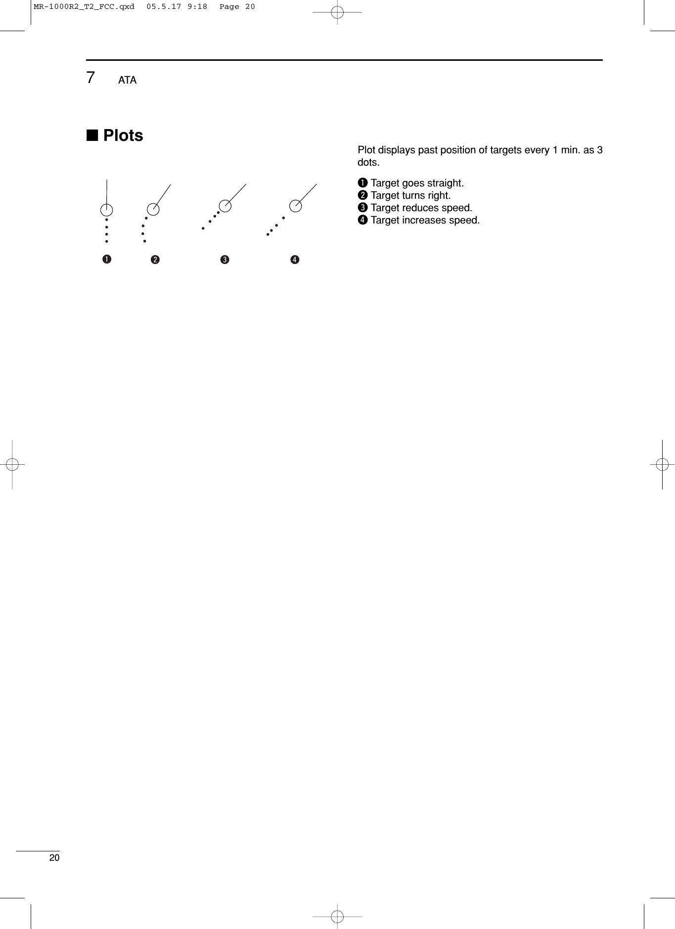
![73MENU■ATA (Automatic Tracking Aid)DATA•OFF : Turn the ATA function OFF.•ON : Turn the ATA function ON.DNo.DISP•OFF : Non display any mark number.•Sel :Display the selected mark numberonly.•ALL : Display all mark numbers.DVECT•TRUE : Select the true vector mode.•REL : Select the relative vector mode.DOWN VECT•OFF : Non display the own ship vector.•ON : Display your own ship’s vector.DALARM (CPA/TCPA)•OFF : Turn the alarm function OFF.•ON : Turn the alarm function ON.DCPA* LIMIT•0.1 to 10.0NM : Set the CPA (Closest Point of Ap-proach) limit with [Ω≈].DTCPA* LIMIT •1 to 60MIN : Set the TCPA (Time to CPA) limit timewith [Ω≈].*CPA/TCPA: Closest Point of Approach and Time to Clos-est Point of Approach limit is defined by the observer togiven warning when a target or targets are close towithin those limits from your own ship.■INT. SETTINGDMAG VAR•AUTO : Revise magnetic variation automatically.NOTE: NMEA data is required. NEVER select“AUTO” without NMEA data, incorrect varia-tion data may entered. (p. 39)•MANUAL : Revise magnetic variation manually. •Push [≈]to select [MANUAL], then push[Ú]. Set the revise value with [Ω≈].Push [Ú] or [MENU] to abort the menu.DBRG INPUT•NMEA : NMEA0183 bearing data format.•N+1 : N+1 data format.•AUX :Other format.•GPS : Reads NMEA0183 COG format data asHDG format.DSPD INPUT•GPS : Use the GPS NMEA speed data.•LOG : Use the speed sensor data.DTX INH START•0 to 359°:Push [Ω≈]to enter the start point of theTX inhibit area.DTX INH ANGLE•0 to 90°:Push [Ω≈]to enter the TX inhibit area.DSAVE TIME•1M, 6M, 15M or 30M : Select the stand by time during savemode.* The radar for TX interval scan is fixed at 10 revolutions.DSYMBOL•1/2/3 : Select the symbol brightness.DCHARACTER•1/2/3 : Select the character brightness.DKEY ILLUM•1/2/3/4 : Select the key illumination brightness.INT. SETTINGBRG INPUTSPD INPUTTX INH STARTTX INH ANGLESAVE TIMESYMBOLCHARACTER BRILLNMEA30MLOG6M 15MMANUALAUTON+1 AUX GPSGPS0˚ 0˚ KEY ILLUMMAG VAR12312312347.2˚ W1MATA MENUVECTNo.DISP OFF ALLOWN VECTALARMCPA LIMITTCPA LIMITTRUEONONONOFFRELOFFOFF1.0NM1 MINATASELMR-1000R2_T2_FCC.qxd 05.5.17 9:18 Page 7](https://usermanual.wiki/ICOM-orporated/271400.Manual/User-Guide-581274-Page-11.png)
![BASIC OPERATION48■Checking the installationBefore turning the power ON, be sure all the connec-tions are complete. The checklist at right may be help-ful for necessary confirmation. DChecklistqThe 4 bolts securing the scanner unit must be firmlytightened. wCabling must be securely attached to a mast ormounting material, and must not interfere with therigging. eBe sure waterproofing procedures are completedon the system cable. rThe power connections to the battery must be of thecorrect polarity.tBe sure that the plugs at the rear of the display unithave been connected correctly and securely. (See p. 24 for details.)CAUTION: Connect the scanner unit before turning thepower ON. Otherwise the magnetron inside the scannerunit might be damaged. ■Turning power ON/OFFqPush [POWER] to turn the power ON.•The initial screen appears and warming up time iscounted down on the screen. •The magnetron inside the scanner unit warms up for 90 sec.•[POWER] does not function for 2 sec. after the power isturned OFF.wWhen the countdown is completed, the Standbyscreen appears. ePush [TX] to start scanning and select the Plan Po-sition Indicator (PPI) screen. •Targets and heading marker appear. •The screen appears approx. 2 sec. after turning thepower on, when ‘AUTO’is selected in the “TUNE” of theVIDEO menu.rPush [POWER] to turn the power OFF. 1(0.25)T.VECT 6M0.000NMNM CURSSOG17.7KT H UP000.0˚THDG253.4˚TEBL1 EBL2 MOB VRM1VRM2CURS 34 ˚ 37.72N 13 5˚ 34.42ESTBYIR COMPASSGPS1(0.25)T.VECT 6M0.000NMNM CURSSOG17.7KT H UP000.0˚THDG253.4˚TEBL1 EBL2 MOB VRM1VRM2CURS 34 ˚ 37.72N 13 5˚ 34.42EIR COMPASSGPS0.45REV *.*ROM OKRAM OKMR-1000R2_T2_FCC.qxd 05.5.17 9:18 Page 8](https://usermanual.wiki/ICOM-orporated/271400.Manual/User-Guide-581274-Page-12.png)
![4BASIC OPERATION9■Basic operationqTurn the power ON.wPush [TX] after the countdown disappears from thescreen. •See “Turning power ON/OFF” on page at left.ePush [+] or [–] several times to select the displayrange. •The screen range readout shows the maximum range ofthe screen.rTurn [GAIN] to set 1 o’clock position.•Clockwise rotation increases the gain. •Increased gain may increase screen noise.tTurn [SEA] to set the sensitivity time control for min-imum.yTurn [RAIN] to set the rain clutter control for mini-mum.uPush [MODE] to select one of Head-up;H UP,Course-up;C UP, North-up;NUP or True Motion;TMscreens. C UP, N UP or TM can be selected only when bear-ing, position or speed data are connected.(See p. 39 for details) NOTE:Manual adjustment can be used. (See below.)TXSAVETARGET TRAILSMODEALM+-MOBMENUEBL2VRM2EBL1VRM1BRILLZOOMOFF CENTPIHL OFFGAINSEARAINPOWEReqwurtyCAUTION: When setting the [SEA] control to a fully clock-wise position, close targets are blanked.DHeading markerThe heading marker is a line that shows your ship’sbow direction. (This marker will appear in the center ofthe screen when the Head-up screen H UP is se-lected.) The heading marker can be hidden when thedesired target is located under the heading marker.•Push and hold [BRILL] and [MENU] simultaneously to hidethe heading marker.DFixed range ringsThe fixed range rings can be used for rough distancemeasurement. (p. 14)Push [MENU] to open the FUNCTION menu, thenpush [Ú] to select RING. Push [≈] to turn the ring ON. DManual tuning The receiver tuning can be manually adjusted. Push [MENU] to open the VIDEO menu, thenselect MANUAL. Push [Ú] to activate the manual tun-ing slider, then push [Ω ≈] to set the tuning level indi-cator to the maximum level. (p. 6)•“M.TUNE” appears on the top of the display.DBrilliance adjustment The intensity of the screen can be adjusted. When yourequire continuous operation, but not constant viewing,a lower setting can increase the life of the CRT display. • Key illumination The backlighting of the keys can be adjusted for con-venient operation. (p. 7)Push [MENU] four times to call up the INT. SETTINGmenu. Push [Ω ≈] to select the illumination level.•Key illumination corresponds with [BRILL] control.NOTE: High intensity will shorten the life of the CRTdisplay. MR-1000R2_T2_FCC.qxd 05.5.17 9:18 Page 9](https://usermanual.wiki/ICOM-orporated/271400.Manual/User-Guide-581274-Page-13.png)
![104BASIC OPERATIONThe following are typical basic operation examples, which may hinder radar reception (sea clutter, precipitation in-terference and echoes from other radar).■RAIN functionThis function eliminates reflection echoes from rain,snow, fog etc. •Rotate the control fully counterclockwise to deactivate thecontrol function. The RAIN indicator ( ) disappears.•NOTE: DO NOT reduce the reflection echoes too much,otherwise you may miss weaker targets. ■SEA functionThis function serves to eliminate echoes from wavesat close range. Reduce the receiver gain for close ob-jects within a radius of 8 miles to eliminate sea clutter.•Rotate the control fully clockwise to activate the automaticcontrol function. SEA indicator ( )appears in the upper leftof the screen.■OFF CENTER functionThe scanning area can be shifted in a desired direc-tion and can be enlarged partially. This is useful whenthe Head-up* is selected and you want to enlarge thebow direction display, or, the center of the screen shiftsin the direction of the intersection. •This function is available for 24NM or shorter range selec-tion.*This function is not available in the TM screen.qPush [Ù Ú Ω ≈] to move the cursor where youwant to shift the center of the screen.• Max. offsetting is up to 75% of the screen.wPush [ALM] and [MODE] simultaneously to shiftthe screen.ePush [ALM] and [MODE] simultaneously again toreturn to the normal screen.With OFF CENTER ONNormal screenAdjust SEA controlEchos from sea wavesAdjust RAIN controlSmall echosWARNING: The [SEA] control reduces the re-ceiver sensitivity of objects within 8 miles. Therefore,caution and careful adjustment are necessary whenusing the [SEA] control. Small objects may not be displayed on the screenwhen strong echoes from the rain or the island within1 NM while automatic SEA function is activating.MR-1000R2_T2_FCC.qxd 05.5.17 9:18 Page 10](https://usermanual.wiki/ICOM-orporated/271400.Manual/User-Guide-581274-Page-14.png)
![114BASIC OPERATION■IR functionRadar interference may appear when another ship’sradar is operating on the same frequency band inclose proximity. The IR function can eliminate this typeof interference. (p. 6)qPush [MENU] to call up VIDEO menu.wPush [Ú] until the “IR” section becomes highlighted.ePush [Ω ≈] to select IR function 1, 2 or OFF.•“IR” appears in the upper right of the screen, when thefunction is activated. ■STRETCH functionThe blips can be magnified electronically for easierviewing of small targets. (p. 6)qPush [MENU] to open the VIDEO menu.wPush [Ú] to select “STRETCH”, then push [≈]toturn the function ON.■ZOOM function The ZOOM function expands the target to two timesnormal size.•This function is available up to a 24 NM range or shorter ex-cept 1⁄8NM.qPush [Ù Ú Ω≈] to move the cursor to the desiredtarget.wPush [TARGET] and [TRAILS] simultaneously totoggle the ZOOM function ON and OFF. •“ZOOM” appears in the lower right of the screen.With ZOOM function ONNormal screenNOTE: Turn OFF this function during normal opera-tion. With STRETCH ONNormal screenWith IR function ONRadar interferenceMR-1000R2_T2_FCC.qxd 05.5.17 9:18 Page 11](https://usermanual.wiki/ICOM-orporated/271400.Manual/User-Guide-581274-Page-15.png)
![124BASIC OPERATION■TRAILS function The trails function memorizes echoes continuously orat constant intervals. This is useful for watching otherships’tracks, approx. relative speed, etc. • Setting the trail interval timeqPush [MENU] twice to call up the VIDEO menu. •Push [Ú] several times until the “TRAIL TIME” sectionbecomes highlighted. wPush [Ω ≈] to select trail interval time. •6 sec., 15 sec., 30 sec., 1 min., 3 min., 6 min., 15 min.and ∞(continuous) are available.ePush [MENU] several times to exit the menu.• Using the TRAILS functionqPush [TRAILS] to turn the trail function ON.•“TRAILS” and trail interval time appears in the upperright of the screen.•Trail interval counter starts to count up to the trail time. wAll displayed echoes at the plotted time are memo-rized and displayed with a graduated intensity to-gether with the current echoes. •Echoes are displayed with minimum intensity when “∞”is selected.ePush [TRAILS] to cancel the trail function and erasethe plotted echoes. •“TRAILS” and trail interval time disappears. Trail time3/4(0.25)M.TUNE 1:0 5NM CURSSTW 15.7KT H UP011.4˚RHDG 253.9˚T6MTRAILSIREST.VECT0.453NMTRAILindicatorTrail intervalcounterTrail time■Power save functionThe power save function conserves the boat’s batterypower by pausing the transmission. The standby(pausing) times are selectable (rotation number is fixedto 10).For example, when 1 min. is selected, the scanner ro-tates 10 revolutions; then stops for 1 min., and then re-peats this sequence while the power save function isactivated. DSetting the scanning standby timeqPush [MENU] four times to call up the INT. SET-TING menu. wPush [Ú] until the “SAVE TIME” section becomeshighlighted.ePush [Ω ≈] to select standby time. •1, 6, 15, and 30 min. are available. rPush [MENU] twice to exit the menu display.DUsing the power save functionqPush and hold [TX (SAVE)] for 1 sec. to turn thepower save function ON. •The save indicator appears in the top of the screen.wAfter the scanning rotations are finished, transmis-sion and rotation are suspended until the selectedstandby time elapses. •The display shows the last scanned echoes until thescanning restarts.•“SAVE” and standby time appear in the top of the screenand the standby time is counted down. eAfter the selected standby time elapses, transmis-sion and rotation restart. rPush [TX (SAVE)] to cancel the power save func-tion.•The save indicator turns OFF. NOTE: When you use the power save function to-gether with the alarm function, the CRT display isturned OFF until an object enters the programmedalarm zone, therefore, more power saving is possi-ble. (p. 17)CURS 34˚ 37.72N CURS 34˚ 37.72N 1(0.25)T.VECT 6M0.900NMNM CURSSOG17.7KT H UP014.6˚THDG273.9˚TIR ESEBL1 EBL2 MOB VRM1VRM213 5˚ 34.42E0:48SAVEPush and hold [TX] for 1 sec.to turn the SAVE function on.Scan and STBY alternatesCount down the standby time1(0.25)T.VECT 6M0.900NMNM CURSSOG17.7KT H UP014.6˚THDG273.9˚TIR ESEBL1 EBL2 MOB VRM1VRM213 5˚ 34.42E0:00SAVECOMPASSGPSCOMPASSGPSMR-1000R2_T2_FCC.qxd 05.5.17 9:18 Page 12](https://usermanual.wiki/ICOM-orporated/271400.Manual/User-Guide-581274-Page-16.png)
![134BASIC OPERATION■Ship speed indicationWhen the ship speed data with NMEA 0183 format isapplied, the radar can display the ship speed. Knots(KT) or kilometers/hour (KM/h) are automatically se-lected in the normal screen (p. 4) by selecting nauticalmiles (NM) or kilometers (KM) respectively. qPush [MENU] several times to call up the FUNC-TION menu.wPush [Ú] until the “DIST UNIT” section becomeshighlighted. ePush [Ω ≈] to turn the ship speed indication to NMor KM. rPush [MENU] several times to exit the menu displayor push [Ú] once to proceed to the position displaysetting.■Position indication When latitude/longitude data with NMEA 0183 formatis applied, the radar can display the latitude and longi-tude of your ship’s or cursor position in the bottom ofthe display. (To display the CURSOR position, bearingdata is necessary.) (p. 39)qPush [MENU] several times to call up the FUNC-TION menu.wPush [Ú] until “POSN DISP” section becomes high-lighted. ePush [Ω ≈] to select the ship position or cursor po-sition.rPush [MENU] several times to exit the menu.■Waypoint indicationWhen waypoint data received from navigation equip-ment with NMEA 0183 format is applied, the radar candisplay the waypoint. To display the waypoint marker,bearing data is necessary. (p. 39)qPush [MENU] several times to call up the FUNC-TION menu.wPush [Ú] until the “WPT” section becomes high-lighted.ePush [Ω ≈] to turn the waypoint indication ON orOFF.rPush [MENU] several times to exit the menu dis-play.■Long pulse function To magnify the blips for easier viewing of small targets,the long pulse and echo stretch (p. 11) functions areavailable. When the long pulse is used in the 3⁄4to 2 NM range, this function magnifies target echoes tothe backward direction of the target. •Pulse selectionqPush [MENU] several times to call up the VIDEOmenu. (p. 6)wPush [Ú] until the “PULSE” section becomes high-lighted. ePush [≈] to select the long pulse.rLong Pulse indication “” appears in the upper leftof the screen.tPush [MENU] several times to exit the menu.■Bearing settingThe radar bearing interface accepts NMEA, N+1 orAUX data format and the bearing can use a magneticor true north type. When a true north type bearing isused, the variation from magnetic north, etc., can beadjusted on 0.1˚ steps. DSetting the bearing typeqPush [MENU] several times to call up the FUNC-TION menu.wPush [Ú] until the “BRG” section becomes high-lighted.ePush [Ω ≈] to select magnetic or true north type. •All displayed bearing readouts show the selected bear-ing type. DSetting the magnetic variationqPush [MENU] several times to call up the INT. SET-TING menu.wPush [Ú] until the “MAG VAR” sections becomeshighlighted.ePush [Ω ≈] to select an AUTO* or MANUAL varia-tion. rWhen a MANUAL variation is selected, push [Ú],then push [Ω ≈] to set the bearing variation. tPush [MENU] to exit the menu display or push [Ú]once to proceed to the bearing input setting.*NOTE: NMEA data is required for auto variation. NEVERselect “AUTO” variation without NMEA data, incorrect varia-tion data may entered.NOTE: Turn SP (Short Pulse) this function duringnormal operation. This function reduces the targetdistance resolution. (p. 23)MR-1000R2_T2_FCC.qxd 05.5.17 9:18 Page 13](https://usermanual.wiki/ICOM-orporated/271400.Manual/User-Guide-581274-Page-17.png)
![5DISTANCE AND DIRECTION MEASUREMENTS14■Distance measurementTwo measurement procedures are available with thisradar. Operating them separately or jointly is possible. The distance unit, nautical miles (NM) or kilometers(KM) is selected in the FUNCTION menu (p. 6).DUsing the fixed ringsqPush [MENU] several times to call up the FUNC-TION menu.wPush [Ú] until the “RING” section becomes high-lighted.ePush [≈]to select RING function ON and displaythe fixed ring.•The interval range appears on the right of the screenrange readout. •The ring range is fixed depending on the screen range.(See below.)rPush [MENU] several times to exit the menu. tTo clear the fixed rings, push [Ω]to select OFF instep e above. DUsing the variable range markerqPush [EBL1 (VRM1)] to display the VRM1 andEBL1; then, push [Ù Ú] to set the marker.• The range between the ship and the target is indicatedin the VRM readouts.wPush [EBL2 (VRM2)] to display the VRM2 andEBL2; then, push [Ù Ú] to set the marker.• The range between the ship and the target is indicatedin the VRM readouts.•When the VRM1 and EBL1 are displayed, the center ofVRM2 appears at the intersection point of the VRM1 andEBL1.•The VRM2 disappears when [EBL1 (VRM1)] is pushed.ePush [EBL1 (VRM1)] to exit the menu display.Range (nm)Ring (nm)1 1.5 2 3 4 6 8 12 16 24 32 36 48*1⁄81⁄41⁄23⁄4255346464646464661122448 861⁄20 1⁄20 1⁄10 1⁄41⁄41⁄41⁄21⁄2NOTE: When the screen is shifted, the number of rings may differ.*Available for the MR-1000TII only.1(0.25)T.VECT0.900NMNM CURSSOG 0.0KT H UP014.6˚THDGIRESEBL1 EBL2 WPT VRM1VRM2CURS 34 ˚ 37.72N 13 5˚ 34.42EFixed ringRing range readoutTYPERINGVRM1VRM2DESCRIPTIONDisplays fixed rings.Suitable for rough estimations from yourown ship to any target.Displays a variable range marker and ac-tivated by the [Ù Ú] for the range markerselector. Suitable for accurate measurements fromyour own ship to a target. Normally functions the same as VRM1.When the VRM1 and EBL1 selects a tar-get, the center of VRM2 appears at theintersection point.Suitable for accurate measurements fromtarget to target. MR-1000R2_T2_FCC.qxd 05.5.17 9:18 Page 14](https://usermanual.wiki/ICOM-orporated/271400.Manual/User-Guide-581274-Page-18.png)
![155DISTANCE AND DIRECTION MEASUREMENTS■Bearing and Distance measurementThis radar has 2 Electronic Bearing Lines (EBL) to in-dicate the target direction from your ship or a target. DUsing the EBL and VRMqPush [Ù Ú Ω≈]to move the cursor on the desiredtarget.wPush [EBL1 (VRM1)] to display the EBL1 andVRM1.•Push [Ω ≈] to rotate the electronic bearing line.•Push [≈] to rotate clockwise and push [Ω] to rotatecounterclockwise.•Push [Ù Ú] to increase or decrease the variable rangemarker ring size.•The EBL1 and VRM1 readouts indicate the target bear-ing and distance. •The EBL readouts indicate the target bearing;0 to 360°R : Relative direction, when ‘360°R’is se-lected in the EBL/PI of the FUNCTIONmenu. (see p. 6)P/S 0 to 180°: Bow direction, when ‘PT/SB’is selectedin the EBL/PI of the FUNCTION menu.(see p. 6)0 to 360°T* : True or magnetic bearing, when select-ing ‘TRUE’in the EBL/PI of the FUNC-TION menu. (see p. 6)*Bearing data is required. (p. 39)ePush [EBL1 (VRM1)] to clear the EBL1 and VRM1.•Cursor remains on the display.rPush [Ù Ú Ω ≈] to move the cursor on the desiredtarget.tPush [EBL2 (VRM2)] to display the EBL2 andVRM2 on the display.•When the EBL1 and VRM1 are displayed, the beginningof EBL2 and VRM2 appears at the intersection point ofthe EBL1 and VRM1. •The EBL2 and VRM2 disappears when [EBL1 (VRM1)]is pushed. yTo clear the EBL1 and VRM1, push [EBL1 (VRM1)]. 3/4TVECT 3M1141NMNM CURS SOG 00km/hH UP3240RHDGIREBL1 3151˚TEBL2 2471˚T WPT 34VRM1 0503NMVRM2 0359NMPOSNEBL1VRM1EBL2EBL1readoutEBL2readoutVRM2VRM1 readoutVRM2 readoutMR-1000R2_T2_FCC.qxd 05.5.17 9:18 Page 15](https://usermanual.wiki/ICOM-orporated/271400.Manual/User-Guide-581274-Page-19.png)
![■Advanced measurementsUsing both Electronic Bearing Lines (EBL) and bothVariable Range Markers (VRM), the following ad-vanced measurements can be made:DMeasuring the distance and direction between 2 targetsqPush [Ù Ú Ω ≈] to move the cursor on the desiredtarget.wPush [EBL1 (VRM1)] to display the EBL1 andVRM1.•Push [Ω ≈] to rotate the electronic bearing line.•Push [Ù Ú] to increase or decrease the variable rangemarker ring size.ePush [EBL2 (VRM2)] to display the EBL2 andVRM2.•The intersection of the EBL1 and VRM1 becomes thecenter of the EBL2 and VRM2.rPush [Ù Ú Ω ≈] to move the cursor on the othertarget.•Push [Ω ≈] to rotate the electronic bearing line.•Push [Ù Ú] to increase or decrease the variable rangemarker ring size.tThe VRM2 readout shows the distance between thetwo targets. The EBL2 readout shows the directionfrom one target to the other. DMeasuring the relative speed and course of a targetqPush [TRAILS] (p. 12) ON; then wait until the trailtime count up reaches to the TRAIL TIME. wSet VRM1 and EBL1 to a previously plotted targetas described above. eSet VRM2 and EBL2 to the current plotted positionof the same target as described as above. rThe VRM2 readout is a measure of target move-ment which can be converted into relative targetspeed. •For example, when a 6 min. trail time is selected, multi-plying the distance by ten gives the relative averagespeed of the target. •If your ship is stationary during the plotting time, theconverted speed and direction become absolute. •The converted speed unit is knots or kilometers/hourwhen the selected unit in the FUNCTION menu is nauti-cal miles (NM) or kilometers (KM), respectively. tThe EBL2 readout shows the course direction of thetarget. • Measuring the distance and course from a waypointqDisplay a waypoint. (see p. 13)wSet VRM1 and EBL1 to the displayed waypoint tar-gets as described above. eSet VRM2 and EBL2 to a target (e.g. the next way-point) as described above. rThe VRM2 readout shows the distance to the targetfrom the waypoint.•The distance unit can be selected as nautical miles (NM)or kilometers (KM) in the FUNCTION menu. tThe EBL2 readout shows the direction to the targetfrom the waypoint. 3/4TVECT 6M1141NMNM CURS\SOG KT H UP3171˚MHDGIR ESEBL1 3211˚TEBL2 1714˚TWPT VRM1 0401NMVRM2 0184NMPOSN VRM2EBL2EBL1VRM13/4MTUNE TVECT 3M1141NMNM CURS\SOGkm/hH UP3171˚MHDGIR ESEBL1 3211˚MEBL2 0890˚TWPT VRM1 0852NMVRM20814NMPOSN ALMGYROGPSEBL2EBL1VRM2VRM15DISTANCE AND DIRECTION MEASUREMENTS16MR-1000R2_T2_FCC.qxd 05.5.17 9:18 Page 16](https://usermanual.wiki/ICOM-orporated/271400.Manual/User-Guide-581274-Page-20.png)
![The unit has an alarm function to protect your ship from collisions. If other ships or islands, etc. come into the pre-programmed alarm zone, the function alerts you with an alarm. You can set the desired range and bearing for analarm zone. While the alarm function is activated, the power save function turns the CRT OFF until an alarm isgiven, to conserve power. ■Alarm zone settingDSetting and using the alarm function qPush [+] or [–] to select the desired range. wPush [Ω ≈ Ù Ú] to set the cursor to the startingpoint of the alarm zone. ePush and hold [ALM] for 1 sec. to enter the alarmzone setting. •The starting zone appears on the screen. (Fig. 1)rPush [Ω≈]to adjust an angle and push [Ù Ú]toset the distance of the alarm zone.•The selected alarm zone appears.tPush [ALM] to fix the alarm zone and activate thealarm function. •“ALM” appears on the bottom of the screen.•The selected alarm zone remains. yIf a target comes into or goes out of the alarm zone,an alarm beep is emitted. •Push [ALM] to cancel the alarm signal and function .uTo deactivate the alarm function, push [ALM].•“ALM” and alarm zone disappear from the screen.iTo activate the alarm function again with the sameprogrammed zone, push [ALM].•“ALM” and pre-programmed alarm zone appears. (Fig. 2)• Using the function with power saverTo activate the power save function, push and hold [TX(SAVE)] for 1 sec. while the alarm function is turnedON. •The CRT display turns OFF.•When a target comes into the alarm zone, an alarm sig-nal is emitted, the CRT display turns ON and the powersave function is cancelled. ■Zone alarm settingZone alarm beep is emitted when the target comesinto the zone, or the target goes out of the zone. (p. 6)qPush [MENU] several times to call up the FUNC-TION menu.wPush [Ú] until the “ZONE ALARM” section becomeshighlighted. ePush [Ω ≈] to select IN or OUT•IN : Alarm sounds when the target comes into thezone. (see Fig. 3)•OUT: Alarm sounds when the target goes out of thezone.Alarm sounds when the targetcomes into the zone.Alarm zoneFig. 3Target (other ship, etc.)3/4(0.25)TVECT 3M0189NMNM CURS\SOG177KT H UP0525˚THDG2739˚TIR ESEBL1 EBL2 WPT VRM1 VRM2 CURS 34˚ 3772N 135˚ 3442EGYROGPSALM3/4(0.25)TVECT 3M0397NMNM CURS\SOG177KT H UP3143˚THDG2739˚TIR ESEBL1 EBL2 WPT VRM1 VRM2 CURS 34˚ 3772N 135˚ 3442EGYROGPSPush [Ω ≈ Ù Ú]“ALM” appearsFig. 1Fig. 2ALARM FUNCTION 617MR-1000R2_T2_FCC.qxd 05.5.17 9:18 Page 17](https://usermanual.wiki/ICOM-orporated/271400.Manual/User-Guide-581274-Page-21.png)
![■ATA (Automatic Tracking Aid)By tracking automatically the target chosen by the cursor key, the closest point of approach (CPA) and the time toclosest point of approach (TCPA) limit of a own ship and a target are calculated.ATA is the function to tell about to alarm sound, when both CPA and TCPA becomes below a setting value (the ap-proach watch area).The range of the target which can be registered is taken as a target with a highest luminosity level of 0.2–16 miles.•Max. 10 targets can be plotted on the screen.•Plot positions shall be identified by an approved symbol mark (p. 20) and associated plot number.•The vector origin will move across the screen at a rate and direction defined by the calculated true or relativecourse and speed.•The vector will be displayed on the target.•Display accuracy may increase by the self-ship and course change of target or acceleration, slowdown, etc.■ATA menu settingSet the ATA menu items before using the ATA function.qPush [MENU] several times to turn the ATA menuON.wPush [≈] to turn the ATA function ON.ePush [Ú] to select the “No. DISP” to select the tar-get identification number type which appears at theright side of the mark. Push [Ω ≈] to select the ap-propriate type.•OFF: No number appears.•SEL: Number appears by the selected mark only.•ALL: All numbers appear by the marks.rPush [Ú] to select “VECT”; push [Ω ≈] to select thevector type.•TRUE (True vector):The predicted true motion of a target as the result of yourown ship’s direction and speed input.•REL (Relative vector):The predicted movement of a target relative to your ownship.tPush [Ú] to select “OWN VECT”; push [Ω ≈] to turnthe own vect function ON or OFF.•OFF: For not displaying the own ship vector. •ON: To display your own ship’s vector. yPush [Ú] to select “ALARM”; push [Ω ≈] to turn thealarm function ON or OFF.•ATA alarm is emitted when both CPA and TCPA reachesthe limit. uPush [Ú] to select the “CPA* LIMIT”; push [Ω ≈] toset the CPA limit distance.iPush [Ú] to select the “TCPA* LIMIT”. Push [Ω ≈]to set the TCPA limit time.*CPA/TCPA: Closest Point of Approach and Time toClosest Point of Approach limit is defined by the ob-server to a given warning when a target or targets areclose to within those limits from your own ship.oPush [MENU] to exit the ATA menu.ATA MENUVECTNo.DISP OFF ALLOWN VECTALARMCPA LIMITTCPA LIMITTRUEONONONOFFRELOFFOFF1.0NM1 MINATASELATA (Automatic Tracking Aid)718MR-1000R2_T2_FCC.qxd 05.5.17 9:18 Page 18](https://usermanual.wiki/ICOM-orporated/271400.Manual/User-Guide-581274-Page-22.png)
![■ATA operationSelect the target which you want to track on the dis-play.qPush [Ù Ú Ω ≈] to move the “+” cursor on the de-sired target.wPush [TARGET] for 1 sec. to select the target fortracking. •Dotted square symbol appears on the cursor.•Target identification number, bearing, distance readout,course (CSE), speed (SPD), CPA and TCPA appear inthe information screen.• Timer starts to count the progressing time.• The vector appears on the target, after the progressingtime of 20 sec. has passed.• It changes to the circle display of a solid line and a vec-tor display, and tracking operation is decided, after theprogressing time of one min. has passed.• When the target which is following disappears, a markchanges to a lozenge and is blinked. A mark disappearsafter one min..• When a target advances within a setting value, a markchanges to a triangle, blinks and sounds alarm sound.Alarm sound will be cancelled if one of key is pushed.• To cancel the target setting, move the cursor on the tar-get, then push [TARGET] for 1 sec.• [TARGET] is pushed for changing the display ofEBL/VRM etc. to target information.• In order to choose target which displays information,cursor is united with target and [TARGET] is pushed.■Plotting marks There are 5 kinds of plotting marks.: Selected, uncalculated mark.: Selected, calculated mark.: Normal, calculated mark.: CPA/TCPA alarm mark. The target isclose to within a minimum range andtime. Alarm emit indicator. Push [TAR-GET] to cancel the alarm.: When the tracking of a target disap-pears.■Course and speed vectorThe vector indicates the target’s predicted, true or rel-ative course and speed. •Vector time may change depending on the TRAIL TIME set-ting. (see VIDEO menu, p. 6)•The tip of the vector shows the target’s predicted positionafter a certain time, which has been selected in the “TRAILTIME”.VectorCurrent positionVector timeTarget’s predicted positon NEW BRG CSE CPA DIST SPD TCPA No.10 BRG 305.7T0:20CSE 081.3TCPA 5.9NMDIST 11.43NMSPD 12.3KTTCPA 0:50Identification No.Bearing Course Distance SpeedPassage of timeClosest Point ofApproachTime to Closest Point ofApproachATA (Automatic Tracking Aid)197MR-1000R2_T2_FCC.qxd 05.5.17 9:18 Page 19](https://usermanual.wiki/ICOM-orporated/271400.Manual/User-Guide-581274-Page-23.png)
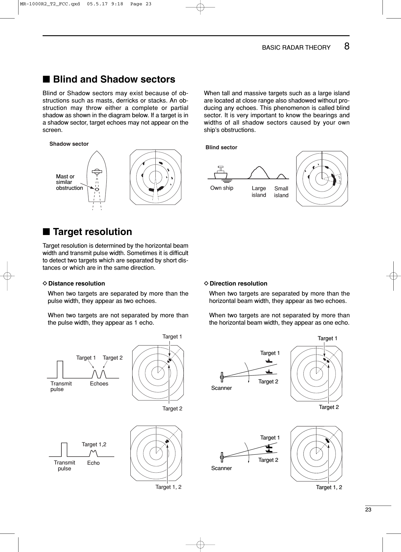
![■Indirect echoesIndirect echoes may be returned from either a passingship, or returned from a reflecting surface, such as amast on your own ship.An indirect echo from a reflecting surface will appearon a different bearing from the direct (true) echo, butthe distance will be approximately the same for both.Indirect echoTrue echoTrue echoFalse echoAn echo is reflected at this point.Own shipTargetBridgeTargetScannerMast orsimilar obstruction■Side-lobe echoesRadiation can escape on each side of the beam insidethe lobes. If a target reflects this radiation, it will be dis-played on the screen as an echo. Side-lobe echoes usually occur at short ranges and asa result of large (strongly reflective) targets. They canbe reduced with proper adjustment of the [SEA] con-trol. See p. 10 for the [SEA] control.FalseechoesTrueechoMain beamSide lobesRadar uses a form of electromagnetic radiation, which like light, can be reflected. Because of this property, someobjects may cause false echoes on the screen where in fact no targets actually exist. These echoes may appear if a large vessel, bridge, or tank is in proximity. Operators should be familiar with the ef-fects of these phenomena. In some cases, echoes can be reduced. 8BASIC RADAR THEORY21MR-1000R2_T2_FCC.qxd 05.5.17 9:18 Page 21](https://usermanual.wiki/ICOM-orporated/271400.Manual/User-Guide-581274-Page-25.png)
![8BASIC RADAR THEORY22■Multiple echoesMultiple echoes may appear when a short-range andstrong echo is received from a ship, bridge, or break-water. Multiple echoes will appear beyond the target’s trueecho point on the same bearing of a large target. Theycan be reduced with proper adjustment of the [SEA]control. See p. 10 for the [SEA] control.True echoFalse echoesOwn ship Another ship■Minimum rangeDetection at short range is very important. Minimumrange is determined primarily by transmitter pulselength, vertical beam width and height of the scannerunit. The shorter the transmission time, the quicker thereturn echoes can be received and their distance mea-sured. The ability to see targets very close to the ship is de-creased if the scanner is mounted too high off thewater, because the bottom of the vertical beam of thescanner cuts off nearby targets.This target can not be recognized with radar.The target in this area can not be recognized.Pulse lengthPulse starting pointVertical beam widthMR-1000R2_T2_FCC.qxd 05.5.17 9:18 Page 22](https://usermanual.wiki/ICOM-orporated/271400.Manual/User-Guide-581274-Page-26.png)
![■Connecting the unitsNMEA1 connection NMEA2 connection■Power source requirementDDC power sourceThe radar is designed for connection to any powersource if the voltage is 10.2–42 V DC, so that a 12, 24,or 32 V DC battery can be used without a DC-DC con-verter, or any internal modifications. • DC power cable connectionConnect the supplied DC power cable as shown in thediagram.■Ground connectionTo prevent electrical shocks and other problems, ground the display unit through the [GND] terminal on the unit’srear panel. For best results, connect a heavy gauge wire or strap to the nearest grounding point on the boat. Thedistance between the [GND] terminal and the ground point should be as short as possible.CAUTION:Incorrect cable connection may dam-age the radar.DC input Groundq N TXT (NMEA 2 output)w RXDi GND u N.Cy AUX input (–); CLOCK or N+1(–) data inputt AUX input (+); CLOCK or N+1(+); data inputr NMEA 1 input (–) or AUX input (–); DATAe NMEA 1 input (+) or AUX input(+); DATA NMEA1:Bearing data inputNMEA2:NMEA 0183 data inputSpeed sensor input+GroundPower supply10.2 to 42 V DCRed: Black: _PWRGNDNEVER connect any-thing other than the sup-plied scanner unit.Supplied scanner unit9INSTALLATION AND CONNECTIONS24q NMEA 2 output (+)w NMEA 2 output (–)e NMEA 2 input (+)u GND (Speed sensor)y Speed sensor inputt Regulated 12 V output. (20 mA Max.)r NMEA 2 input (–)MR-1000R2_T2_FCC.qxd 05.5.17 9:18 Page 24](https://usermanual.wiki/ICOM-orporated/271400.Manual/User-Guide-581274-Page-28.png)
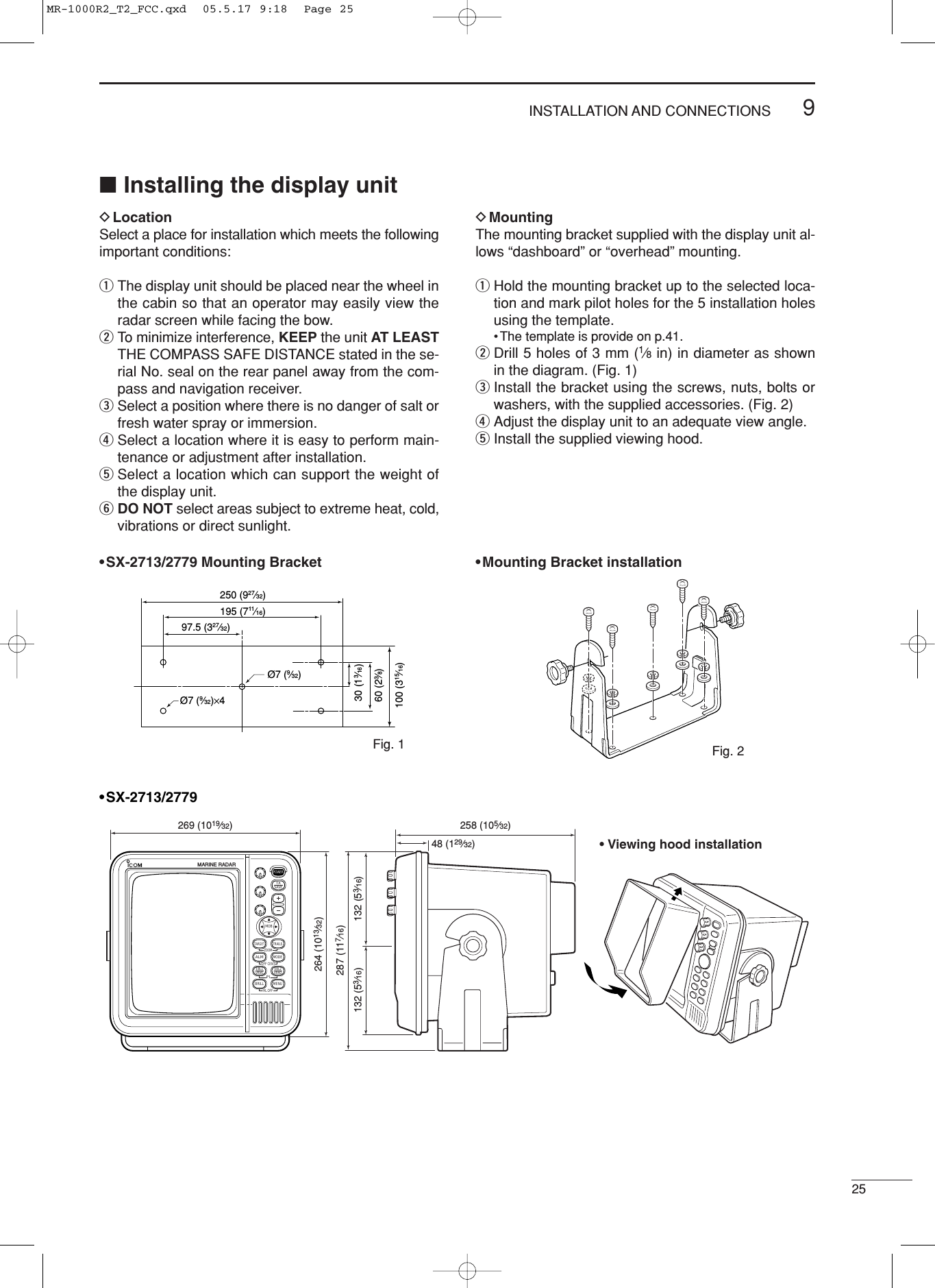
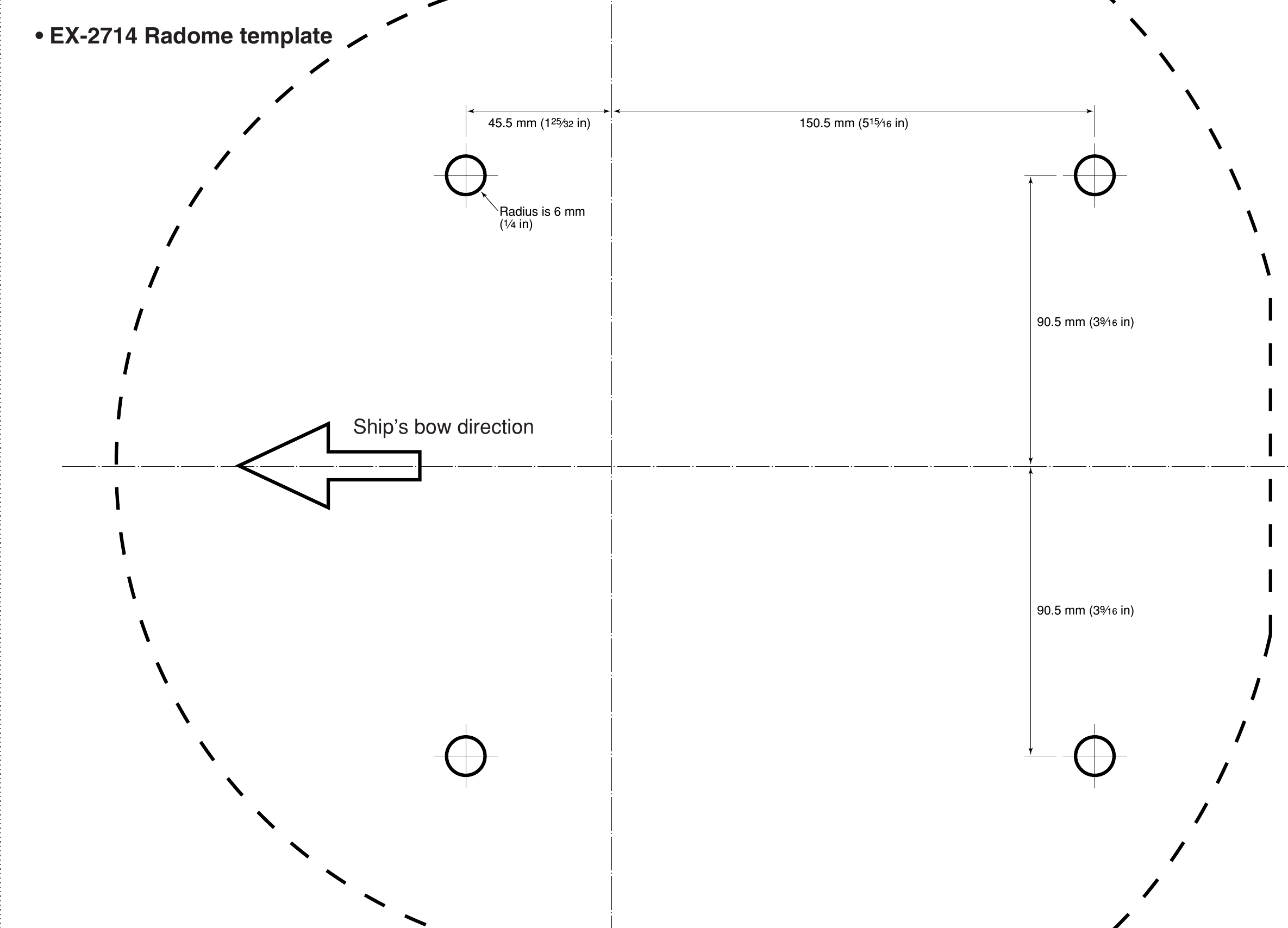
![926■Mounting the EX-2714 scanner unitDLocationThe scanner unit is designed to be weatherproof andcompletely watertight. Select a place for installationwhich meets the following important conditions.qThe scanner unit must be near the boat’s center lineand have a good view in every direction. Be surethere are no objects in the surrounding area whichwill intercept the scanning beam.wKEEP the scanner unit away from any smoke-stacks. Smoke can damage the unit. eWhen the boat is equipped with a radio directionalfinder (RDF) system, keep the scanner unit at least2 m (6.6 ft) away from any RDF antenna. • Radiation from the scanner unit can affect the measure-ment data of RDF equipment. rThe unit should be placed as high as possible (atleast 5.5 m; 18 ft vertically above the main deck and allpossible personnel) on the boat to obtain best perfor-mance with maximum range. (See p. 51 for details)tIf you install two or more radar in one boat, installone above, and one below. yThe mounting surface must be parallel with theboat’s waterline.uIf the height is insufficient to install the scanner unit,build a special frame for installation. DMounting qDrill four holes of 12 mm (1⁄2in) in diameter usingthe template. wIf the mounting surface or platform is metal, applysealing compound around the holes to prevent cor-rosion and to waterproof the unit. eFix the scanner unit to the selected position withbolts of 10 mm (3⁄8in) in diameter, with flat andspring washers. The supplied bolts are two lengths:25 mm (1 in) or 50 mm (2 in).CAUTION: SECURE the four bolts tightly. WARNING: BE SURE [POWER] is OFF when-ever you are working with the scanner unit.607 (2329⁄32)45.5 (113⁄16) 150.5 (515⁄16)243 (99⁄16)90.5 (39⁄16)90.5 (39⁄16)Ship’s bow direction Ship’s bow directionUnit: mm (in)INSTALLATION AND CONNECTIONSMR-1000R2_T2_FCC.qxd 05.9.5 16:38 Page 26](https://usermanual.wiki/ICOM-orporated/271400.Manual/User-Guide-581274-Page-30.png)
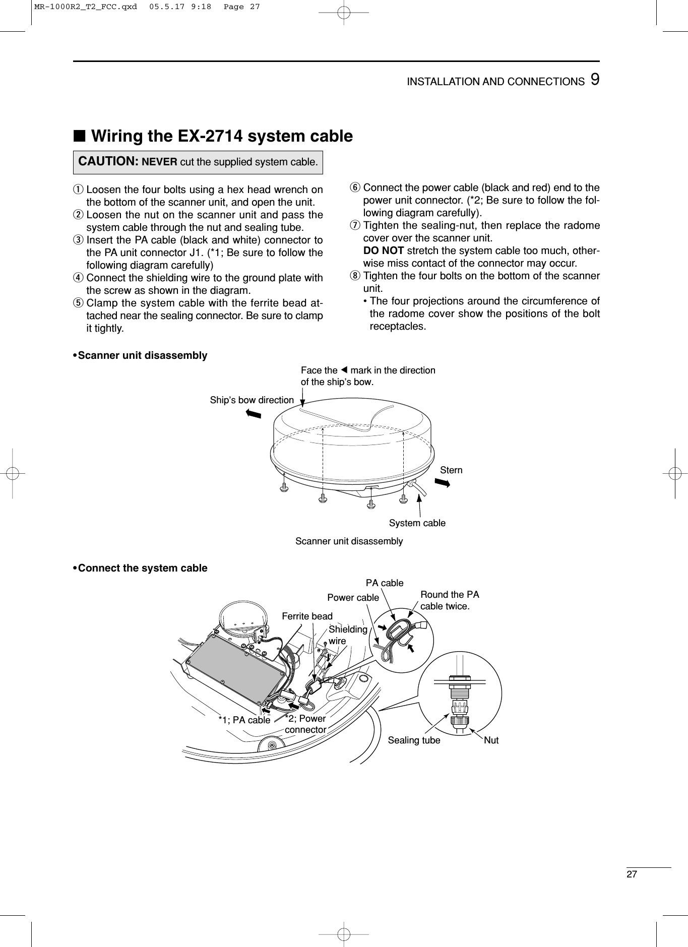
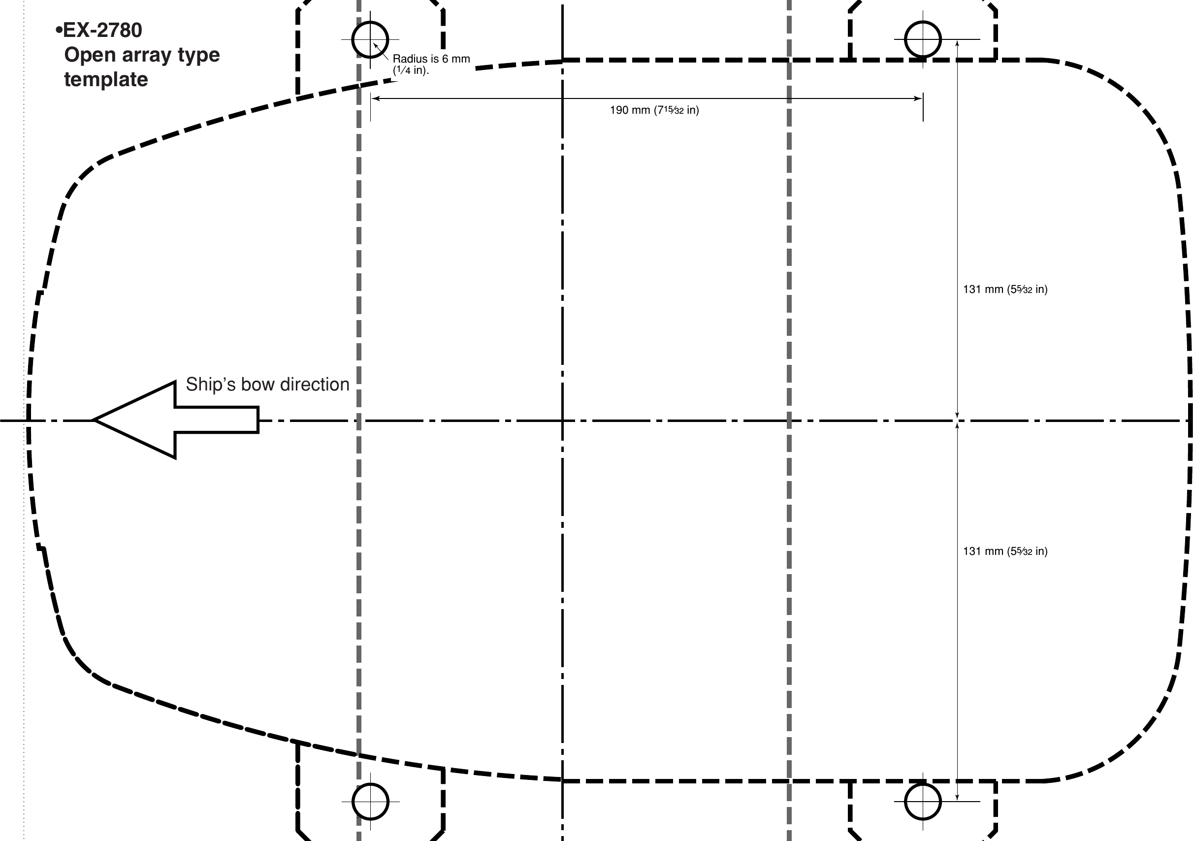
![■Mounting the EX-2780 scanner unit• LocationThe scanner unit is designed to be weatherproof andcompletely watertight. Select a place for installationwhich meets the following important conditions.qThe scanner unit must be near the boat’s center lineand have a good view in every direction. Be surethere are no objects in the surrounding area whichwill intercept the scanning beam.wKEEP the scanner unit away from any smoke-stacks. Smoke can damage the unit. eWhen the boat is equipped with a radio directionalfinder (RDF) system, keep the scanner unit at least2 m (6.6 ft) away from any RDF antenna. • Radiation from the scanner unit can affect the measure-ment data of RDF equipment. rThe unit should be placed as high as possible (atleast 5.5 m; 18 ft vertically above the main deck and allpossible personnel) on the boat to obtain best perfor-mance with maximum range. (See p. 51 for details)tIf you install two or more radar in one boat, installone above, and one below. yThe mounting surface must be parallel with theboat’s waterline.uIf the height is insufficient to install the scanner unit,build a special frame for installation. • Mounting qDrill four (4) holes of 12 mm (1⁄2in) in diameterusing the template. wIf the mounting surface or platform is metal, applysealing compound around the holes to prevent cor-rosion and to waterproof the unit. eFix the scanner unit to the selected position withbolts of 10 mm (3⁄8in) in diameter, with flat andspring washers. The supplied bolts are two lengths:25 mm (1 in) or 50 mm (2 in).CAUTION: SECURE the four bolts tightly. Ship’s bow direction190 (715⁄32)399 (1723⁄32)381 (15)289INSTALLATION AND CONNECTIONSShip’s bow direction302 (1129⁄32)248 (93⁄4)1200 (471⁄4)20.5 (13⁄16)R5.5 (7⁄32)11 (7⁄16)262 (105⁄16)281 (111⁄16) 98 (37⁄8)152 (531⁄32)190 (715⁄32)WARNING: BE SURE [POWER] is OFF when-ever you are working with the scanner unit.MR-1000R2_T2_FCC.qxd 05.9.5 16:38 Page 28](https://usermanual.wiki/ICOM-orporated/271400.Manual/User-Guide-581274-Page-32.png)
![1031OTHER FUNCTIONSDAntenna rotation speedThe antenna rotation speed can be selected from 48rpm and 36 rpm. (Default: 48 rpm)Pushing and holding [–] for 1 sec. to select 36 rpm ro-tation speed, pushing and holding [+] for 1 sec. to se-lect 48 rpm rotation speed. DTest pattern indicationTo check the CRT indication distortion, a test patterncan bee displayed.While pushing and holding [MENU], turn power ON todisplay the test pattern.To return to normal operating condition, turn powerOFF then ON again.DPara-simulation screenThe MR-1000RII/TII has para-simulation screen capa-bility.qWhile pushing and holding [BRILL], turn power ON.wAfter the count down indication, stand-by screen ap-pears.ePush [TX (SAVE)] to display the para-simulationscreen.rTo return to normal operating condition, turn powerOFF then ON again.DAll resetqWhile pushing and holding [TARGET], [EBL1(VRM1)] and [EBL2 (VRM2)], turn power ON.wFollow the guidance.MR-1000R2_T2_FCC.qxd 05.5.17 9:18 Page 31](https://usermanual.wiki/ICOM-orporated/271400.Manual/User-Guide-581274-Page-35.png)
![1132SERVICE MAN MENU■Service man menuTo open the “SERVICE MAN” menu.Push [MENU] several times to show the “SERVICEMAN” menu.■Select the languageMenu screens can be displayed in 2 differentlanguages.Selectable languages; ENGLISH, (Hangul)After opening the “SERVICE MAN” menu;qPush [Ù] to show the present language.wPush [Ω≈] to select desired language, then push[Ú] to continue the setting.ePush [MENU] to exit the “SERVICE MAN” menu.DTIMING ADJ.•Corrects the distance.DHDG ADJ.•Adjusts the electronic heading line adjustment.DSPD ADJ.•Enter the pulse rate of the speed sensor.DRANGE•1⁄8, 1⁄4, 1⁄2, 3⁄4, 1, 1.5, 2, 3, 4, 6, 8, 12, 16, 24, 32, 36,48* : Choose the selectable screen range.*MR-1000TII onlyDSETUP MEMORY•The present setting value is displayed by pushing [≈],then select the desired item from “RECALL” and“SAVE” using with [Ú].qPush [≈] to display “RECALL” and “SAVE”.wPush [ÙÚ] to select “RECALL” or “SAVE”.ePush [≈].•“SURE ?” is displayed.rPush [≈]to perform.tPush [Ω]to cancel.•When recall is performed without saving a setup, itwill become an initial value at the time of factoryshipments.DOther readouts•OUTPUT VOLTAGE: Shows the voltage level for thescanner unit from the display unit.•HV (High voltage) : Shows the voltage level in thehigh-voltage unit in the scannerunit.•MONITOR : Shows the voltage level forchecking the receiver unit opera-tion.•HEATER : Shows the heater current.•MG :Shows the current level for theMagnetron.•TX TIME :Shows the total transmitted time.SERVICE MANSPD ADJ.HDG ADJ. 0.0˚HVSETUP MEMORY RECALLRANGE24000 MONITORHEATER5731.0HTX TIME30.0OUTPUTENGLISHVOLTAGESAVE MG340753.00.55TIMING ADJ.1/8 3/4 2 61/4 1 3 81/2 1.5 4 121624323648CAUTION: The SERVICE MAN MENU is availablefor service purposes only. DO NOT change any set-ting on the menu, otherwise the equipment may notoperate at it’s original performance.MR-1000R2_T2_FCC.qxd 05.5.17 9:18 Page 32](https://usermanual.wiki/ICOM-orporated/271400.Manual/User-Guide-581274-Page-36.png)
![3311SERVICE MAN MENU■TIMING adjustmentThe system cable length affects the sweep timing.When the cable length adjustment is not correct, astraight target is shown as a curved echo. Thus, cablelength adjustment is necessary.qPosition your boat near a straight target such asbreakwater, wharf, etc. wPush [–] several times to select 1⁄8or 1⁄4NM range.ePush [TX (SAVE)] to display the target on thescreen. rPush [MENU], [Ú] and [≈] several times to displaythe “SERVICE MAN” menu.tPush [Ú] until the “TIMING ADJ.” section becomeshighlighted.yPush [Ω≈]to adjust the echo until it becomesstraight. (see below)uPush [MENU] to return to the normal screen.Proper adjustment Improper, pulling inward Improper, pushing outward■HDG adjustmentIf the heading marker line differs from the exact bowdirection, correct the heading marker line as follows.This function may be helpful when the scanner has notbeen mounted exactly in the direction of the bow.qLine up the bow of the boat with an identifiable tar-get.wPush [TX (SAVE)] to display the target on thescreen.ePush [MENU], [Ú] and [≈] several times to displaythe “SERVICE MAN” menu.rPush [Ú] until the “HDG ADJ.” section becomeshighlighted.tPush [Ω ≈] to adjust, until the target matches theheading marker. (the difference can be read out onthe menu screen)yPush [MENU] to return to the normal screen.1T.VECT0.000NMNM CURSSOG H UP000.0˚RHDG IR ESSERVICE MANSPD ADJ.0.0˚HVSETUP MEMORYRANGE24000 MONITORHEATER5731.0HTX TIME30.0OUTPUTENGLISHVOLTAGEMG340753.00.55TIMING ADJ.1/8 3/4 2 6 16 361/4 1 3 8 241/2 1.5 4 32HDG ADJ.1T.VECT0.000NMNM CURSSOG H UP000.0˚RHDG IR ESSERVICE MANSPD ADJ.10.0˚HVSETUP MEMORYRANGE24000 MONITORHEATER5731.0HTX TIME30.0OUTPUTENGLISHVOLTAGEMG340753.00.55TIMING ADJ.1/8 3/4 2 6 16 361/4 1 3 8 241/2 1.5 4 32HDG ADJ.48124812Push [Ω ≈]Angle of differenceMR-1000R2_T2_FCC.qxd 05.5.17 9:18 Page 33](https://usermanual.wiki/ICOM-orporated/271400.Manual/User-Guide-581274-Page-37.png)
![3411 SERVICE MAN MENU■SPD adjustmentqPush [MENU], [Ú] and [≈] several times to displaythe “SERVICE MAN” menu.wPush [Ú] until the “SPD ADJ.” section becomeshighlighted.ePush [Ω≈]to enter the pulse rate (pulse numbersper one nautical mile) of the speed sensor unit.rPush [MENU] to return to the normal screen.■RANGE selectionqPush [MENU], [Ú] and [≈] to display the “SERVICEMAN” menu.wPush [Ú] until the “RANGE” section becomes high-lighted.ePush [Ù Ú] to choose the selectable screen rangeswith [+] or [–] on the display.rPush [Ω]to skip from the range selection, or push[≈] to cancel skipping.tPush [MENU] to return to the normal screen.Selectable ranges: 1⁄8, 1⁄4, 1⁄2, 3⁄4, 1, 1.5, 2, 3, 4, 6, 8,12, 16, 24, 32, 36, 48* (NM)*48 NM range is available for the MR-1000TII only.SERVICE MANSPD ADJ.HDG ADJ. 0.0˚HVSETUP MEMORY24000 MONITORHEATER5731.0HTX TIME30.0OUTPUTENGLISHVOLTAGEMG340753.00.55TIMING ADJ.1/8 3/4 2 61/4 1 3 81/2 1.5 4 121624323648RANGE*1⁄4 NM range will be skipped.MR-1000R2_T2_FCC.qxd 05.5.17 9:18 Page 34](https://usermanual.wiki/ICOM-orporated/271400.Manual/User-Guide-581274-Page-38.png)