ICOM orporated 277500 VHF Transceivers User Manual FA SC61VC 2
ICOM Incorporated VHF Transceivers FA SC61VC 2
Contents
- 1. User Manual
- 2. Revised User Manual
- 3. Antenna Manual
- 4. Updated User Manual
Antenna Manual

Thank you for purchasing the
FA-SC61VC
VHF ANTENNA
.
Please read these instructions
thoroughly before using the
FA-SC61VC.
0
145 MHz
150 MHz
155 MHz
160 MHz
165 MHz
170 MHz
175 MHz
140 MHz
136 MHz
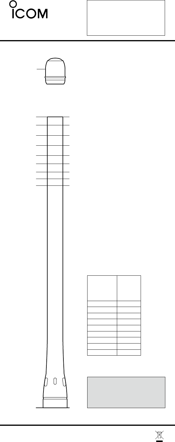
Antenna cap
FA-SC61VC
The optimum bandwidth is ±3%
of the tuned frequency.
For optimum performance
tune
to the center transmit
frequency
of the radio.
Cutting Instructions
qAlign the bottom of
the
anten-
na onto the 0 position of
the
cutting guide diagram at left.
wMark the antenna at the
length corresponding to
the
desired frequency to be
tuned.
FA-SC61VC
A-6532K-1EX-wPrinted in Japan
eCut the antenna to the
marked length.
• Use a wire cutter that
can
cut at least 1.2 mm (d)
of
piano wire.
rApply adhesive to the top
of
the antenna and attach
the
supplied antenna cap.
• Use of Cemedine
Co.
Super-X No. 8008
black
(Icom parts
number:
8950002910) or similar
is
recommended.
The ant enna can be used at its or
iginal length for this frequency.
No tuning (cutting) is necessary.
*
© 2006-2009 Icom Inc.
Antenna Cutting
Chart
Center
frequency
(MHz)
Length
(mm)
174*
169
163
157
151
146
141
137
133
136
140
145
150
155
160
165
170
175
NOTE:
Antenna cap must be inserted after
cutting the element otherwise water
immersion makes the element damaged.
CAUTION:
Making antenna cuts at other than
the prescribed lengths specified could
void the user's authority to operate
the equipment.