ICOM orporated 277601 UHF Transceivers User Manual IC F3011 F3013 F4011 F4013 Instruction Manual
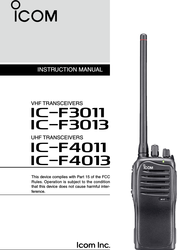
ICOM Incorporated UHF Transceivers IC F3011 F3013 F4011 F4013 Instruction Manual
Contents
- 1. Users Manual
- 2. Antenna Manual
- 3. User Manual
- 4. Revised User Manual
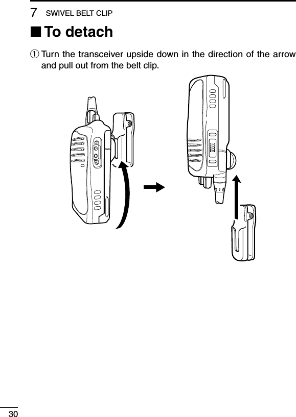
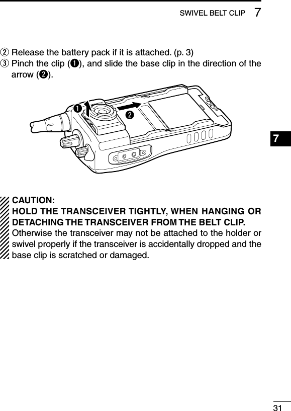
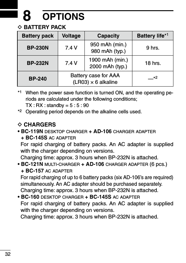
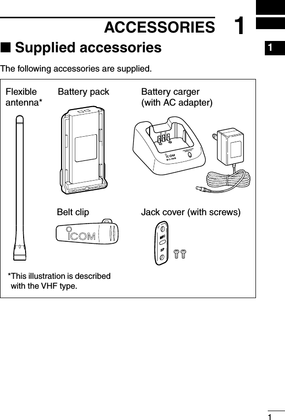
User Manual
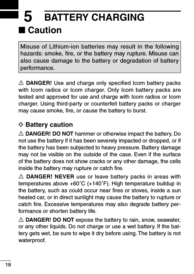
![ivR CAUTION! NEVER hold the transceiver so that the antenna is very close to, or touching exposed parts of the body, especially the face or eyes, while transmitting. The transceiver will perform best if the microphone is 5 to 10 cm (2 to 4 in.) away from the lips and the transceiver is vertical.R CAUTION! NEVER operate the transceiver with a headset or other audio accessories at high volume levels.R CAUTION! NEVER short the terminals of the battery pack.R CAUTION! NEVER use non-Icom battery packs/chargers to prevent the loss of the transceiver’s good performance and warranty.R CAUTION! NEVER expose the transceiver to rain, snow or any liquids. The transceiver may be damaged.DO NOT push [PTT] when not actually desiring to transmit.DO NOT use or place the transceiver in direct sunlight or in areas with temperatures below –30°C (+22°F) or above +60°C (+140°F).DO NOT modify the transceiver. The transceiver warranty does not cover any problems caused by unauthorized modification.MAKE SURE the flexible antenna and battery pack are securely attached to the transceiver, and that the antenna and battery pack are dry before attachment. Exposing the inside of the transceiver to water will result in serious damage to the transceiver.The use of non-Icom battery packs/chargers may impair trans-ceiver performance and invalidate the warranty.For U.S.A. onlyCAUTION! Changes or modifications to this device, not expressly approved by Icom Inc., could void your authority to operate this transceiver under FCC regulations.PRECAUTIONS](https://usermanual.wiki/ICOM-orporated/277601.User-Manual/User-Guide-1129865-Page-5.png)
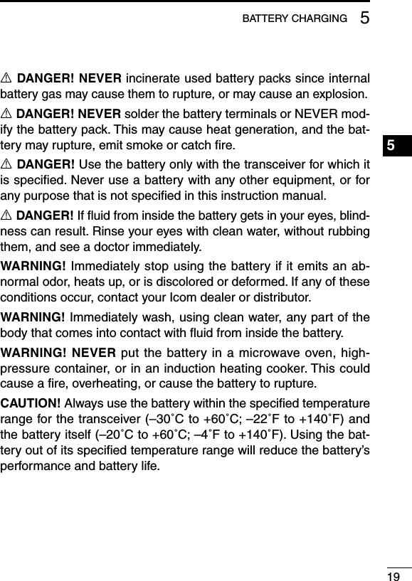
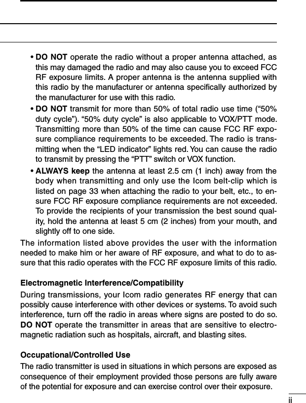
![41ACCESSORIESD Jack cover Attach the jack cover when the optional speaker-microphone is not used.To attach the jack cover:q Attach the jack cover to the [SP MIC] connector.w Tighten the screws.To detach the jack cover:e Unscrew the screws with a phillips screwdriver.r Detach the jack cover for the optional equipment connec-tion.eerwwq](https://usermanual.wiki/ICOM-orporated/277601.User-Manual/User-Guide-1129865-Page-10.png)
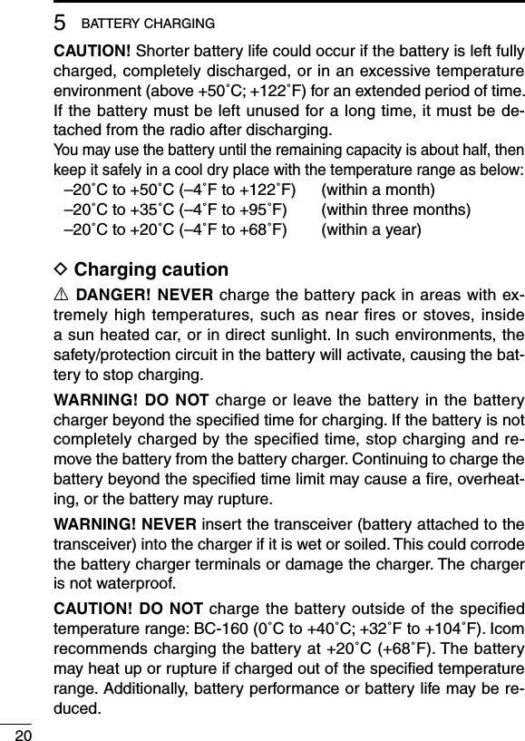
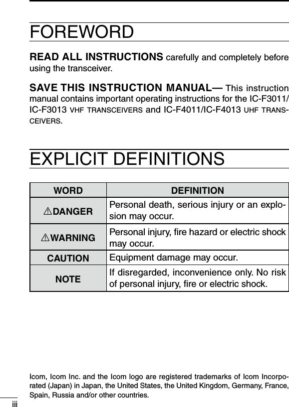
![62PANEL DESCRIPTION■ Front, top and side panelsMicrophoneSpeakerrweyuitqq CHANNEL SELECTOR Rotate the channel selector to select the pre-programmed mem-ory channels.w VOLUME CONTROL [VOL] Rotate to turn the power ON/OFF and adjust the audio level.](https://usermanual.wiki/ICOM-orporated/277601.User-Manual/User-Guide-1129865-Page-12.png)
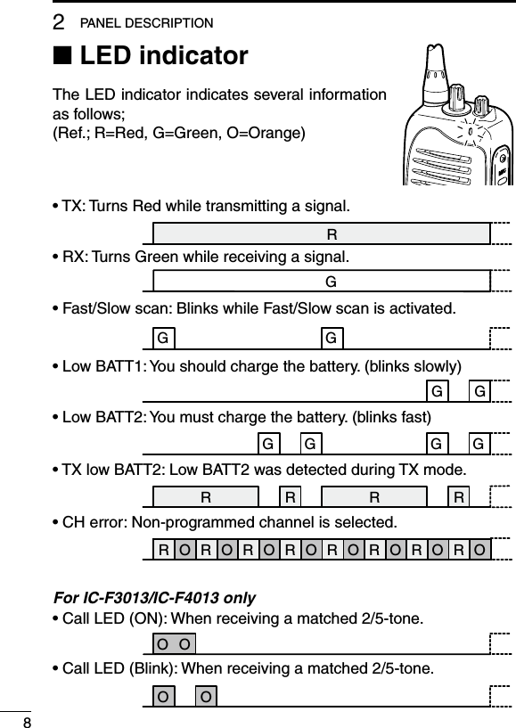
![72PANEL DESCRIPTIONe LED INDICATOR (p. 8) ➥ Lights red while transmitting. ➥ Lights green while receiving a signal, or when the squelch is open. ➥ Lights/blinks orange when the matched 2/5-tone code is re-ceived, according to the pre-programming. (For IC-F3013/F4013 only)r SPEAKER-MICROPHONE CONNECTOR [SP MIC] Connects the optional speaker-microphone, earphone, etc.[SP MIC] jack coverNOTE: Attach the [SP MIC] jack cover when the optional equip-ment is not used. (p. 4) t DEALER-PROGRAMMABLE KEY [Lower] The desired function can be assigned by your dealer. (p. 9)y PTT SWITCH [PTT]Push and hold to transmit; release to receive.u DEALER-PROGRAMMABLE KEY [Upper] The desired function can be assigned by your dealer. (p. 9)i ANTENNA CONNECTOR Connects the supplied antenna.1234567891011121314151617181920](https://usermanual.wiki/ICOM-orporated/277601.User-Manual/User-Guide-1129865-Page-13.png)
![92PANEL DESCRIPTION■ Programmable function keysThe following functions can be assigned to [Upper] and [Lower] programmable function keys.Consult your Icom dealer or system operator for details concerning your transceivers programming.D For All modelsSCAN A KEY➥ Push to start and cancel scanning operation.➥ When the Power ON scan function is turned ON, push to pause the scanning operation. The paused scan restarts after the spec-ified time period has passed.SCAN B KEYPush to start and cancel scanning operation. In case of transmis-sion during scan, pauses scanning. The paused scan restarts after the specified time period has passed.PRIORITY CHANNEL KEYS➥ Push to select the Priority A or Priority B channel.➥ Push and hold [Prio A (Rewrite)] to rewrite the Prio A channel.MR-CH 1/2/3/4 KEYSPush to select a memory channels 1 to 4 directly.1234567891011121314151617181920](https://usermanual.wiki/ICOM-orporated/277601.User-Manual/User-Guide-1129865-Page-15.png)
![102PANEL DESCRIPTIONOUTPUT POWER SELECTION KEYSelect the transmit output power temporarily or permanently, de-pending on the pre-setting.• Ask your dealer for the output power level for each selection.TALK AROUND KEY➥ Push to turn the talk around function OFF.➥ Push and hold to turn the talk around function ON. • The talk around function equalizes the transmit frequency to the receive frequency for transceiver-to-transceiver communication.WIDE/NARROW KEY➥ Push to select the IF bandwidth to wide. • The wide passband width can be selected from 25 or 20 kHz using the optional cloning software (PMR operation only). Ask your dealer for details.➥ Push and hold to select the IF bandwidth to narrow.SIREN KEYPush to emit a siren. This function can be used for situations other than an emergency alert such as a security alarm for example.LOCK KEYPush and hold to electronically lock all programmable keys except the followings: [Moni(Audi)], [Call] (incl. Call A and Call B)* and [Emergency Single]/[Emergency Repeat] (incl. Silent)*.* Available for IC-F3013/IC-F4013 only.](https://usermanual.wiki/ICOM-orporated/277601.User-Manual/User-Guide-1129865-Page-16.png)
![112PANEL DESCRIPTIONMONITOR KEY ➥ Push to mute and release the CTCSS (DTCS) or 2Tone* squelch mute. Open any squelches/deactivate any mutes while pushing this key. (LMR operation only) * Available for the IC-F3013/F4013 only.➥ Activates one of (or two of) the following functions on each chan-nel independently: (PMR operation only) • Push and hold to un-mute the channel (audio is emitted; ‘Audible’). • Push to mute the channel (audio is not emitted; ‘Inaudible’). • Push to send a ‘reset code’ after the communication is finished. NOTE: The un-mute condition (‘Audible’ condition) may auto-matically return to the mute condition (‘Inaudible’ condition) after a specified period.D For IC-F3013/IC-F4013 onlyDTMF AUTODIAL KEYPush to transmit the programmed DTMF code.CALL KEYSPush to transmit a 2/5-tone code.• Call transmission is necessary before you call another station depend-ing on your signalling system.• [Call A] and/or [Call B] keys may be available when your system em-ploys selective ‘Individual/Group’ calls. Ask your dealer which call is assigned to each key.EMERGENCY SINGLE/EMERGENCY REPEAT KEYS➥ Push and hold for the specified time period to transmit an emer-gency call once or repeatedly.➥ When [Emergency Single (Silent)] or [Emergency Repeat (Silent)] is pushed, an emergency call is transmitted with no beep emission. • If you want to cancel the emergency call, push (or push and hold) the key again before transmitting the call. • The emergency call is transmitted one time only or repeatedly until receiving a control code depending on the pre-setting.1234567891011121314151617181920](https://usermanual.wiki/ICOM-orporated/277601.User-Manual/User-Guide-1129865-Page-17.png)
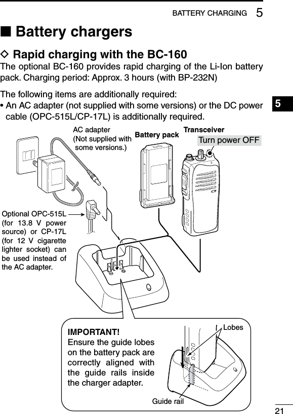
![123CONVENTIONAL OPERATION■ Turning power ONRotate [VOL] to turn power ON.■ Channel selectionRotate [CHANNEL SELECTOR] to se-lect the desired operating channel, in sequence; or, push one of [MR-CH 1] to [MR-CH 4] key to select a channel di-rectly.AUTOMATIC SCAN TYPE:Channel setting is not necessary for this type. When turning the power ON, the transceiver automatically starts scanning. Scanning stops when receiving a call.[VOL][CHANNEL SELECTOR]](https://usermanual.wiki/ICOM-orporated/277601.User-Manual/User-Guide-1129865-Page-18.png)
![133CONVENTIONAL OPERATION■ Receiving and transmittingNOTE: Transmitting without an antenna may damage the trans-ceiver. See p. 2 for antenna attachment.Receiving:q Rotate [VOL] to turn power ON.w Rotate [CHANNEL SELECTOR] or push one of [MR-CH 1] to [MR-CH 4] key to select a channel.e When receiving a call, adjust the audio output level to a comfort-able listening level.Transmitting:Wait for the channel to become clear to avoid interference.q While pushing and holding [PTT], speak into the microphone at a normal voice level.w Release [PTT] to return to receive.IMPORTANT: To maximize the readability of your signal;1. Pause briefly after pushing [PTT].2. Hold the microphone 5 to 10 cm (2 to 4 inches) from your mouth, then speak into the microphone at a normal voice level.1234567891011121314151617181920](https://usermanual.wiki/ICOM-orporated/277601.User-Manual/User-Guide-1129865-Page-19.png)
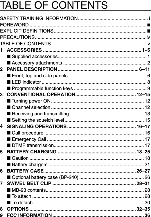
![153CONVENTIONAL OPERATION■ Setting the squelch levelThe squelch circuit mutes the received audio signal depending on the signal strength.q While pushing [PTT] and [Lower], rotate [VOL] to turn the power ON to enter the squelch level adjust-ment mode.w Push [Upper] to increase the squelch level (tight squelch) or [Lower] to decrease the squelch level (loose squelch).e Rotate [VOL] to turn the power OFF to fix the squelch level.1234567891011121314151617181920[VOL][Upper][Lower][PTT]](https://usermanual.wiki/ICOM-orporated/277601.User-Manual/User-Guide-1129865-Page-21.png)
![164SIGNALING OPERATIONSNOTE: The tone signalling operations are available for the IC-F3013/F4013 only.■ Call procedureWhen your system employs tone signalling (excluding CTCSS and DTCS), the call procedure may be necessary prior to voice trans-mission. The tone signalling employed may be a selective calling system which allows you to call specific station(s) only and prevent unwanted stations from contacting you.q Select the desired TX code channel or 2/5-tone code according to your System Operator’s instructions. • This may not be necessary depending on programming.w Push [Call]. (p. 11)e After transmitting a 2/5-tone code, the remainder of your com-munication can be carried out in the normal fashion.Selective calling Non-selective callingD Transmitting notes— PTTID callThe transceiver sends the ID code (5-tone, DTMF or digital ANI) automatically when [PTT] is pushed (beginning of transmission) and released (end of transmission) depends on the setting.](https://usermanual.wiki/ICOM-orporated/277601.User-Manual/User-Guide-1129865-Page-22.png)
![174SIGNALING OPERATIONS1234567891011121314151617181920■ Emergency CallWhen [Emergency Single] or [Emergency Repeat] (p. 11) is pushed and held for the specified time period, the emergency sig-nal (5-tone, DTMF or MDC 1200) is transmitted once or repeatedly on the emergency channel. A repeat emergency signal is auto-matically transmitted until it receives the acknowledgement signal. When no emergency channel is specified, the signal is transmitted on the previously selected channel.If you want to cancel the emergency call, push and hold the key again before transmitting the call.The emergency call can be transmitted without a beep emission, and the LCD indication if [Emergency Single (Silent)] or [Emer-gency Repeat (Silent)] (p. 11) is pushed.The transceiver can also be programmed to keep the microphone open during an emergency call, allowing monitoring of the situa-tion.IMPORTANT: It is recommended to set an emergency channel individually to provide the certain emergency call operation.■ DTMF transmissionIf the transceiver has [DTMF Autodial] assigned to it, the auto-matic DTMF transmission function is available.➥ Push [DTMF Autodial] to transmit the DTMF code.](https://usermanual.wiki/ICOM-orporated/277601.User-Manual/User-Guide-1129865-Page-23.png)