ICOM orporated 277601 UHF Transceiver User Manual IC F14 F24
ICOM Incorporated UHF Transceiver IC F14 F24
Contents
- 1. Users Manual
- 2. Antenna Manual
- 3. User Manual
- 4. Revised User Manual
Users Manual
INSTRUCTION MANUAL
This device complies with Part 15 of the FCC
rules. Operation is subject to the condition that
this device does not cause harmful interfer-
ence.
UHF TRANSCEIVER
iF24/S
VHF TRANSCEIVER
iF14/S
!IC-F14_F24.qxd 04.6.17 6:22 PM Page A (1,1)

iii
SAFETY TRAINING INFORMATION
Your Icom radio generates RF electromagnetic energy
during transmit mode. This radio is designed for and clas-
sified as “Occupational Use Only”, meaning it must be
used only during the course of employment by individuals
aware of the hazards, and the ways to minimize such haz-
ards. This radio is NOT intended for use by the “General
Population” in an uncontrolled environment.
This radio has been tested and complies with the FCC RF exposure lim-
its for “Occupational Use Only”. In addition, your Icom radio complies with
the following Standards and Guidelines with regard to RF energy and
electromagnetic energy levels and evaluation of such levels for exposure
to humans:
• FCC OET Bulletin 65 Edition 97-01 Supplement C, Evaluating Com-
pliance with FCC Guidelines for Human Exposure to Radio Fre-
quency Electromagnetic Fields.
• American National Standards Institute (C95.1-1992), IEEE Standard
for Safety Levels with Respect to Human Exposure to Radio Fre-
quency Electromagnetic Fields, 3 kHz to 300 GHz.
• American National Standards Institute (C95.3-1992), IEEE Recom-
mended Practice for the Measurement of Potentially Hazardous Elec-
tromagnetic Fields– RF and Microwave.
• The following accessories are authorized for use with this product.
Use of accessories other than those specified may result in RF ex-
posure levels exceeding the FCC requirements for wireless RF ex-
posure.; Belt Clip (MB-94), Rechargeable Li-Ion Battery Pack
(BP-231) and Speaker-microphone (HM-131L).
To ensure that your expose to RF electromagnetic
energy is within the FCC allowable limits for occupa-
tional use, always adhere to the following guidelines:
CAUTION
WARNING
• DO NOT operate the radio without a proper antenna attached, as this
may damaged the radio and may also cause you to exceed FCC RF
exposure limits. A proper antenna is the antenna supplied with this
radio by the manufacturer or antenna specifically authorized by the
manufacturer for use with this radio.
• DO NOT transmit for more than 50% of total radio use time (“50%
duty cycle”). Transmitting more than 50% of the time can cause FCC
RF exposure compliance requirements to be exceeded. The radio is
transmitting when the “Transmit indicator” lights red. You can cause
the radio to transmit by pressing the “PTT” switch.
• ALWAYS keep the antenna at least 2.5 cm (1 inch) away from the
body when transmitting and only use the Icom belt-clip which is listed
on page 33 when attaching the radio to your belt, etc., to ensure FCC
RF exposure compliance requirements are not exceeded. To provide
the recipients of your transmission the best sound quality, hold the
antenna at least 5 cm (2 inches) from your mouth, and slightly off to
one side.
The information listed above provides the user with the information
needed to make him or her aware of RF exposure, and what to do to as-
sure that this radio operates with the FCC RF exposure limits of this radio.
Electromagnetic Interference/Compatibility
During transmissions, your Icom radio generates RF energy that can pos-
sibly cause interference with other devices or systems. To avoid such in-
terference, turn off the radio in areas where signs are posted to do so.
DO NOT operate the transmitter in areas that are sensitive to electro-
magnetic radiation such as hospitals, aircraft, and blasting sites.
Occupational/Controlled Use
The radio transmitter is used in situations in which persons are exposed
as consequence of their employment provided those persons are fully
aware of the potential for exposure and can exercise control over their
exposure.
!IC-F14_F24.qxd 04.6.17 6:22 PM Page i (1,1)

iviii
FOREWORD
READ ALL INSTRUCTIONS carefully and completely before
using the transceiver.
SAVE THIS INSTRUCTION MANUAL— This instruction
manual contains important operating instructions for the IC-F14/
F14S
VHF TRANSCEIVER
and IC-F24/F24S
UHF TRANSCEIVER
.
EXPLICIT DEFINITIONS
OPERATING NOTES
• When transmitting with a portable radio, hold the radio in a vertical
position with its microphone 5 to 10 centimeters (2 to 4 inches)
away from your mouth. Keep the antenna at least 2.5 centimeters
(1 inch) from your head and body.
• If you wear a portable two-way radio on your body, ensure that the
antenna is at least 2.5 centimeters (1 inch) from your body when
transmitting.
WORD DEFINITION
RWARNING Personal injury, fire hazard or electric shock
may occur.
NOTE If disregarded, inconvenience only. No risk
of personal injury, fire or electric shock.
CAUTION Equipment damage may occur.
PRECAUTION
RWARNING! NEVER hold the transceiver so that the antenna
is very close to, or touching exposed parts of the body, especially
the face or eyes, while transmitting. The transceiver will perform
best if the microphone is 5 to 10 cm (2 to 4 inches) away from the
lips and the transceiver is vertical.
RWARNING! NEVER operate the transceiver with a headset
or other audio accessories at high volume levels.
CAUTION! NEVER short the terminals of the battery pack.
NEVER connect the transceiver to a power source other than the
BP-230, BP-231 or BP-232. Such a connection will ruin the trans-
ceiver.
DO NOT push the PTT when not actually desiring to transmit.
AVOID using or placing the transceiver in direct sunlight or in
areas with temperatures below –22°F (–30°C) or above +140°F
(+60°C).
DO NOT modify the transceiver for any reason.
MAKE SURE the flexible antenna and battery pack are securely
attached to the transceiver, and that the antenna and battery pack
are dry before attachment. Exposing the inside of the transceiver
to water will result in serious damage to the transceiver.
The use of non-Icom battery packs/chargers may impair transceiver
performance and invalidate the warranty.
FCC caution:
Changes or modifications to this device, not expressly approved by
Icom Inc., could void your authority to operate this transceiver under
FCC regulations.
Icom, Icom Inc. and the logo are registered trademarks of Icom Incorpo-
rated (Japan) in the United States, the United Kingdom, Germany, France, Spain,
Russia and/or other countries.
!IC-F14_F24.qxd 04.6.17 6:22 PM Page iii (1,1)
1
1
ACCESSORIES
1
v
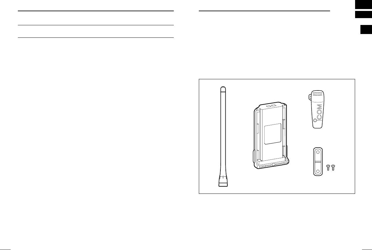
■Supplied accessories
The following accessories are supplied: Qty.
qFlexible antenna . . . . . . . . . . . . . . . . . . . . . . . . . . . . . . . . . . . .1
wBattery pack . . . . . . . . . . . . . . . . . . . . . . . . . . . . . . . . . . . . . . .1
eBelt clip . . . . . . . . . . . . . . . . . . . . . . . . . . . . . . . . . . . . . . . . . . .1
rJack cover (with screws) . . . . . . . . . . . . . . . . . . . . . . . . . . .1 set
qwe
r
TABLE OF CONTENTS
SAFETY TRAINING INFORMATION …………………………………… i
FOREWORD ……………………………………………………………… iii
EXPLICIT DEFINITIONS ………………………………………………… iii
OPERATING NOTES …………………………………………………… iii
PRECAUTION …………………………………………………………… iv
TABLE OF CONTENTS ………………………………………………… v
1 ACCESSORIES ……………………………………………………… 1–5
‘Supplied accessories………………………………………………… 1
‘Accessory attachments……………………………………………… 2
2 PANEL DESCRIPTION …………………………………………… 6–11
‘Front, top and side panels ………………………………………… 6
‘LED indicator ………………………………………………………… 8
‘Programmable function keys ……………………………………… 9
3 CONVENTIONAL OPERATION ………………………………… 12–18
‘Turning power ON ………………………………………………… 12
‘Channel selection ………………………………………………… 12
‘Call procedure ……………………………………………………… 13
‘ Receiving and transmitting ……………………………………… 14
‘ Scrambler function ………………………………………………… 16
‘ Setting the squelch level ………………………………………… 16
‘ Man Down Emergency Call ……………………………………… 17
4 OPTIONAL UNIT INSTALLATION……………………………… 18–19
‘Optional unit installation …………………………………………… 18
‘Scrambler unit installation ………………………………………… 19
5 BATTERY CHARGING ………………………………………… 20–25
‘Battery charging …………………………………………………… 20
‘Caution ……………………………………………………………… 21
‘Optional battery chargers ………………………………………… 22
6 SWIVEL BELT CLIP……………………………………………… 26–29
‘MB-93 contents …………………………………………………… 26
‘To attach …………………………………………………………… 26
‘To detach …………………………………………………………… 28
7 SPEAKER-MICROPHONE ……………………………………… 30–31
‘Optional HM-75A description ……………………………………… 30
‘To attach …………………………………………………………… 31
8 OPTIONS ………………………………………………………… 32–33
!IC-F14_F24.qxd 04.6.17 6:22 PM Page v (1,1)
3
1
ACCESSORIES
1
2
1ACCESSORIES
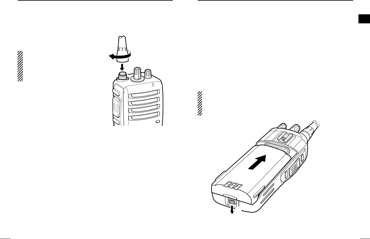
■Accessory attachments
DFlexible antenna
Connect the supplied flexible an-
tenna to the antenna connector.
CAUTION:
• NEVER HOLD by the antenna
when carrying the transceiver.
• Transmitting without an antenna
may damage the transceiver.
ïBattery pack
To attach the battery pack:
Slide the battery pack on the back of the transceiver in the direc-
tion of the arrow (q), then lock it with the battery release button.
• Slide the battery pack until the battery release button makes a ‘click’
sound.
To release the battery pack:
Push the battery release button in the direction of the arrow (w) as
shown below. The battery pack is then released.
NEVER release or attach the battery pack when the transceiver
is wet or soiled. This may result in water or dust getting into the
transceiver/battery pack and may result in the transceiver being
damaged.
q
w
!IC-F14_F24.qxd 04.6.17 6:22 PM Page 2 (1,1)
4
1ACCESSORIES
5
1
ACCESSORIES
1
ïJack cover
Attach the jack cover when the optional speaker-microphone is not
used.
w
w
q
q
q
w
To attach the jack cover:
qAttach the jack cover to the
[SP MIC] connector.
wTighten the screws.
To detach the jack cover:
qUnscrew the screws with a
phillips screwdriver.
wDetach the jack cover for the
speaker-microphone connec-
tion.
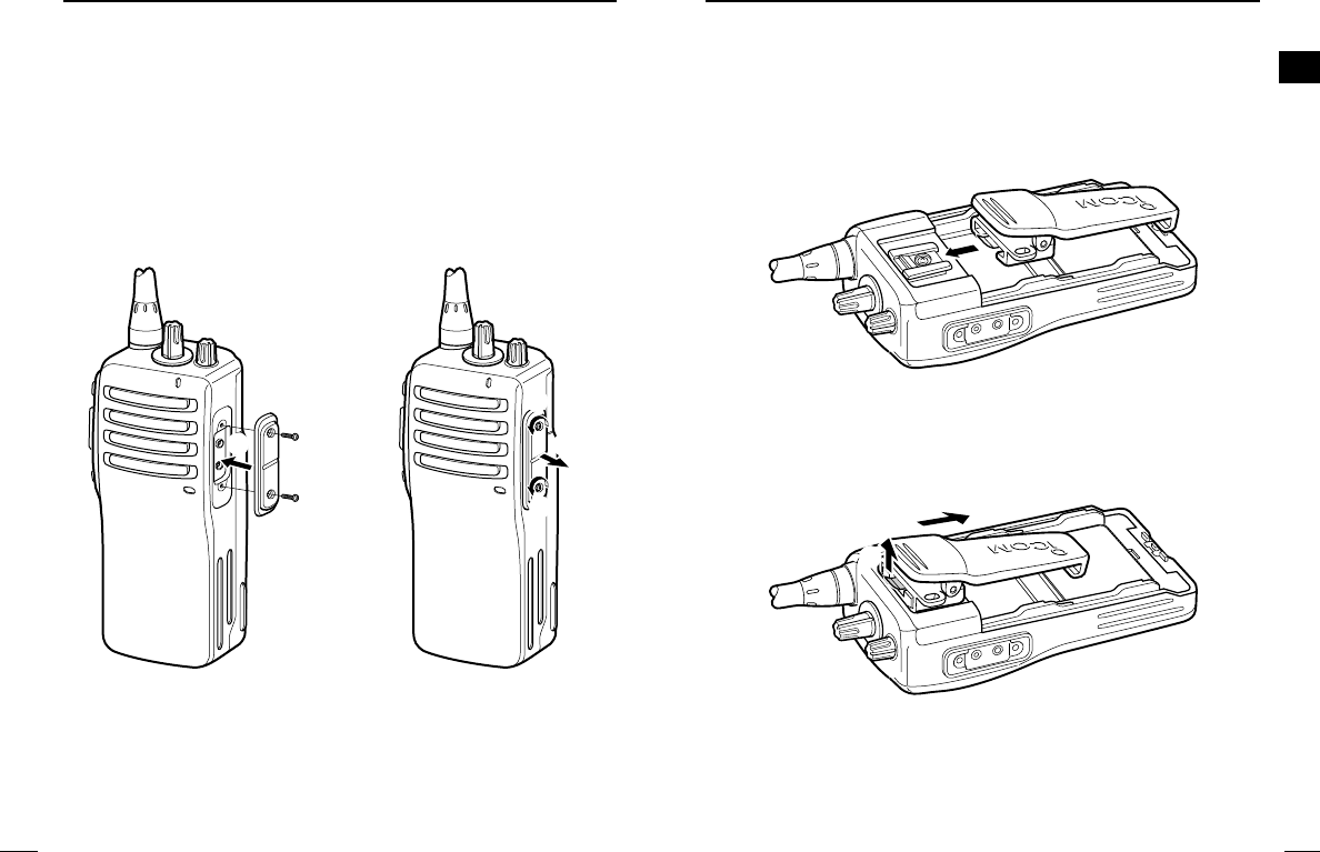
DBelt clip
To attach the belt clip:
qRelease the battery pack if it is attached.
wSlide the belt clip in the direction of the arrow until the belt clip is
locked and makes a ‘click’ sound.
To detach the belt clip:
qRelease the battery pack if it is attached.
wPinch the clip (q), and slide the belt clip in the direction of the
arrow (w).
q
w
!IC-F14_F24.qxd 04.6.17 6:22 PM Page 4 (1,1)
7
2
PANEL DESCRIPTION
2
6
2PANEL DESCRIPTION
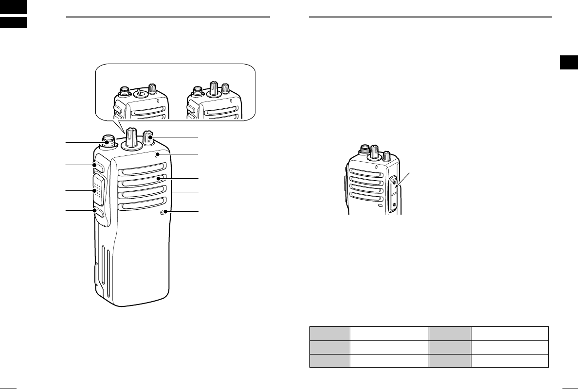
■Front, top and side panels
qCHANNEL SW/SELECTOR
• IC-F14S/F24S: Toggle the channel switch to select the pre-pro-
grammed channel 1 or 2.
• IC-F14/F24 : Rotate the channel selector to select the pre-
programmed memory channels.
wVOLUME CONTROL [VOL]
Rotate to turn the power ON/OFF and adjust the audio level.
r
q
w
y
u
i
e
Microphone
Speaker
t
IC-F14S/F24S IC-F14/F24
eLED INDICATOR (p. 8)
➥Lights red while transmitting.
➥Lights green while receiving a signal, or when the squelch is
open.
➥Lights/blinks orange when the matched 2/5-tone code is re-
ceived, according to the pre-programming.
rSPEAKER-MICROPHONE CONNECTOR [SP MIC]
Connects the optional speaker-microphone. (p. 31)
tDEALER-PROGRAMMABLE KEY [Lower]
The desired function can be assigned by your dealer. (p. 9)
yPTT SWITCH [PTT]
Push and hold to transmit; release to receive.
uDEALER-PROGRAMMABLE KEY [Upper]
The desired function can be assigned by your dealer. (p. 9)
iANTENNA CONNECTOR
Connects the supplied antenna.
DDProgrammable key reference
*These functions are available when the optional Speaker-Microphone
is connected. (p. 31)
Upper
Mic Up*
Mic A*
Lower
Mic Down*
Mic B*
[SP MIC] jack cover
NOTE: Attach the [SP MIC] jack
cover when the optional speak-
er-microphone is not used. (p. 4)
!IC-F14_F24.qxd 04.6.17 6:22 PM Page 6 (1,1)
9
2
PANEL DESCRIPTION
2
8
2PANEL DESCRIPTION
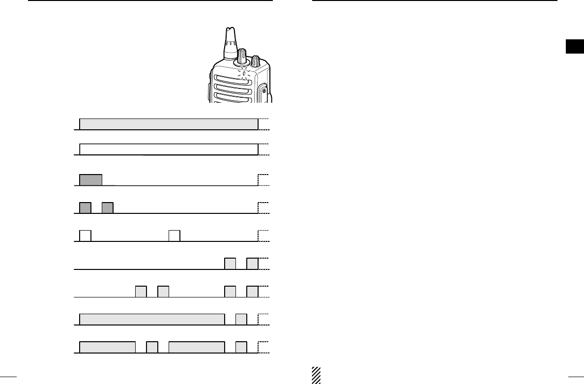
‘‘LED indicator
The LED indicator indicates several informa-
tion as follows;
(Ref.; R=Red, G=Green, O=Orange)
R R R R
R R
O O
O O
R R R R
R R
G
G G
R
•TX: Turns Red while transmitting a signal.
•RX: Turns Green while receiving a signal.
•Call LED (ON): When receiving a matched 2/5-tone.
•Call LED (Blink): When receiving a matched 2/5-tone.
•Fast/Slow scan: Blinks while Fast/Slow scan is activated.
•Low BATT1: You should charge the battery. (blinks slowly)
•Low BATT2: You must charge the battery. (blinks fast)
•TX low BATT1: Low BATT1 was detected during TX mode.
•TX low BATT2: Low BATT2 was detected during TX mode.
■Programmable function keys
The following functions can be assigned to [Upper], [Lower], [Mic
Up]*, [Mic Down]*, [Mic A]* and [Mic B]* programmable function
keys.
Consult your Icom dealer or system operator for details concerning
your transceivers programming.
If the programmable function names are bracketed in the following
explanations, the specific key used to activate the function depends
on programming.
*These keys are available when the optional Speaker-Microphone is
connected. (p. 31)
SCAN A KEY
➥This key’s operation depends on the Power ON Scan setting.
When the power ON scan function is turned OFF;
Push to start and cancel scanning operation. In case of trans-
mission during scan, cancels scanning.
When the power ON scan function is turned ON;
Push to pause scanning. Scanning resumes after passing a
specified time period. In case of transmission during scan,
pauses scanning. Scanning resumes after passing a specified
time period.
SCAN B KEY
Push to start and cancel scanning operation. In case of transmis-
sion during scan, pauses scanning. Scanning resumes after pass-
ing a specified time period.
PRIORITY CHANNEL KEYS
➥Push to select the Priority A or Priority B channel.
➥Push and hold [Prio A (Rewrite)] to rewrite the Prio A channel.
MR-CH 1/2/3/4 KEYS
Push to select a memory channels 1 to 4 directly.
NOTE: The memory channels 3 and 4 are available for IC-
F14S/F24S when [MR-CH 3] and [MR-CH 4] keys are assigned.
!IC-F14_F24.qxd 04.6.17 6:22 PM Page 8 (1,1)

10
2PANEL DESCRIPTION
11
2
PANEL DESCRIPTION
2
MONITOR KEY
➥Mute and release the CTCSS (DTCS) or 2-tone squelch mute.
Open any squelch/deactivate any mute while pushing this key.
(LMR operation only)
➥Activates one of (or two of) the following functions on each chan-
nel independently: (PMR operation only)
• Push and hold to un-mute the channel (audio is emitted; ‘Audible’
condition).
• Push to mute the channel (sets to ‘Inaudible’only).
• Push to un-mute the channel (sets to ‘Audible’only).
• Push after the communication is finished to send a ‘reset code’.
NOTE: The un-mute condition (‘Audible’condition) may auto-
matically return to the mute condition (‘Inaudible‘ condition)
after a specified period.
LOCK KEY
Push and hold to electronically lock all programmable keys except
the following:
[Call] (incl. Call A and Call B), [Moni(Audi)] and [Emergency] keys.
OUTPUT POWER SELECTION KEY
Select the transmit output power temporarily or permanently, de-
pending on the pre-setting.
•Ask your dealer for the output power level for each selection.
TALK AROUND KEY
Turn the talk around function ON and OFF.
•The talk around function equalizes the transmit frequency to the re-
ceive frequency for transceiver-to-transceiver communication.
WIDE/NARROW KEY
➥Push to select the IF bandwidth to wide.
➥Push and hold to select the IF bandwidth to narrow.
• The wide passband width can be selected from 25.0 or 20.0 kHz
using the CS-F14
CLONING SOFTWARE
. (PMR operation only) Ask
your dealer for details.
DTMF AUTODIAL KEY
Push to transmit the programmed DTMF code.
CALL KEYS
Push to transmit a 2/5-tone code.
•Call transmission is necessary before you call another station de-
pending on your signalling system.
•[Call A] and/or [Call B] keys may be available when your system em-
ploys selective ‘Individual/Group’calls. Ask your dealer which call is
assigned to each key.
EMERGENCY KEYS
➥Push and hold to transmit an emergency call.
➥When [Emergency Single (Silent)] or [Emergency Repeat
(Silent)] is pushed, an emergency call is transmitted without a
beep emission.
• If you want to cancel the emergency call, push (or push and hold)
the key again before transmitting the call.
• The emergency call is transmitted one time only or repeatedly until
receiving a control code depending on the pre-setting.
VOICE SCRAMBLER FUNCTION KEYS
➥Push to turn the voice scrambler function OFF.
➥Push and hold to turn the voice scrambler function ON.
OPT OUT KEYS
➥Push to inactivate the connected output signal level.
➥Push and hold to activate the connected output signal level.
SIREN KEY
Push to emit a siren. This function can be used for situations other
than an emergency alert such as a security alarm for example.
!IC-F14_F24.qxd 04.6.17 6:22 PM Page 10 (1,1)
13
3
CONVENTIONAL OPERATION
3
12
3CONVENTIONAL OPERATION
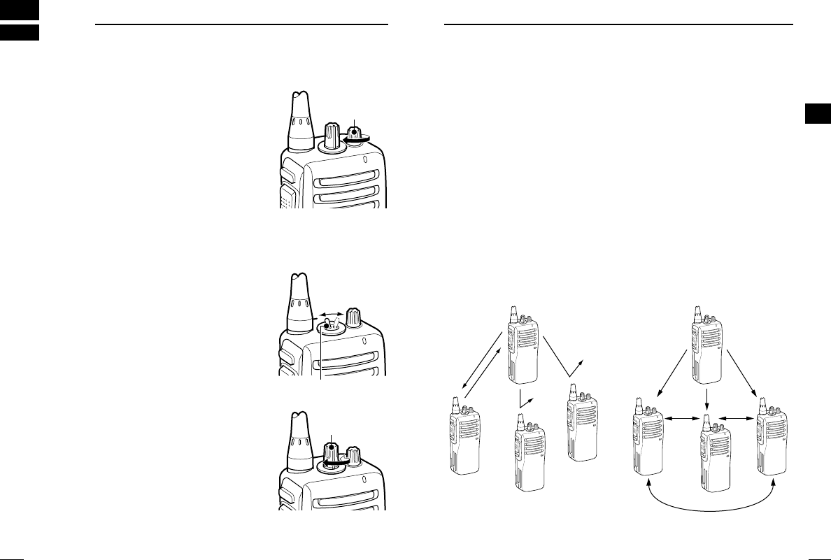
■Turning power ON
➥Rotate [VOL] to turn power ON.
■Channel selection
IC-F14S/F24S:
Toggle [CHANNEL SWITCH] to select
the channel 1 or 2, or, push one of [MR-
CH 1] to [MR-CH 4] key to select a chan-
nel directly.
• The memory channels 3 and 4 are avail-
able when [MR-CH 3] and [MR-CH 4]
keys are assigned.
IC-F14/F24:
Rotate [CHANNEL SELECTOR] to se-
lect the desired operating channel, in se-
quence; or, push one of [MR-CH 1] to
[MR-CH 4] key to select a channel di-
rectly.
AUTOMATIC SCAN TYPE:
Channel setting is not necessary for this type. When turning the
power ON, the transceiver automatically starts scanning. Scanning
stops when receiving a call.
[VOL]
[CHANNEL
SELECTOR]
[CHANNEL SWITCH]
■Call procedure
When your system employs tone signalling (excluding CTCSS and
DTCS), the call procedure may be necessary prior to voice trans-
mission. The tone signalling employed may be a selective calling
system which allows you to call specific station(s) only and prevent
unwanted stations from contacting you.
qSelect the desired TX code channel or 2/5-tone code according
to your System Operator’s instructions.
• This may not be necessary depending on programming.
wPush the call key (assigned to one of the dealer programmable
keys). (p. 9)
eAfter transmitting a 2/5-tone code, the remainder of your com-
munication can be carried out in the normal fashion.
Selective calling Non-selective calling
!IC-F14_F24.qxd 04.6.17 6:22 PM Page 12 (1,1)

15
3
CONVENTIONAL OPERATION
3
14
3CONVENTIONAL OPERATION
■Receiving and transmitting
NOTE: Transmitting without an antenna may damage the trans-
ceiver. See p. 2 for antenna attachment.
Receiving:
qRotate [VOL] to turn power ON.
wToggle [CHANNEL SWITCH] (IC-F14S/F24S), rotate [CHAN-
NEL SELECTOR] (IC-F14/F24) or push one of [MR-CH 1] to
[MR-CH 4] key to select a channel.
For IC-F14S/F24S:
The memory channels 3 and 4 are available when [MR-CH 3]
and [MR-CH 4] keys are assigned.
eWhen receiving a call, adjust the audio output level to a comfort-
able listening level.
Transmitting:
Wait for the channel to become clear to avoid interference.
qWhile pushing and holding [PTT], speak into the microphone at
a normal voice level.
• When a tone signalling system is used, the call procedure de-
scribed on p. 13 may be necessary.
wRelease [PTT] to return to receive.
IMPORTANT!: To maximize the readability of your signal;
1. Pause briefly after pushing [PTT].
2. Hold the microphone 5 to 10 cm (2 to 4 inches) from your
mouth, then speak into the microphone at a normal voice
level.
DTransmitting notes
• Transmit inhibit function
The transceiver has several inhibit functions which restrict trans-
mission under the following conditions:
- The channel is in mute condition.
- Channel is busy.
- Un-matched (or matched) CTCSS is received.
- The selected channel is a ‘receive only’channel.
• Time-out timer
After continuous transmission for the pre-programmed time period, the
time-out timer activates, and causes the transceiver to stop transmit-
ting.
• Penalty timer
Once the time-out timer activates, transmission is further inhibited
for a period determined by the penalty timer.
DDTMF transmission
If the transceiver has [DTMF Autodial] assigned to it, the automatic
DTMF transmission function is available.
➥Push [DTMF Autodial] to transmit the DTMF code.
!IC-F14_F24.qxd 04.6.17 6:22 PM Page 14 (1,1)
17
3
CONVENTIONAL OPERATION
3
16
3CONVENTIONAL OPERATION
■Scrambler function
The optional voice scrambler units UT-109 (#01) and UT-110 (#01)
provide high performance private communication between stations
with the same scrambler codes.
➥Push and hold [Scrambler] to turn the scrambler function ON.
➥Push [Scrambler] to turn the scrambler function OFF.
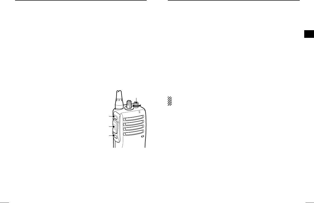
■Setting the squelch level
The squelch circuit mutes the received audio signal depending on
the signal strength.
qWhile pushing [PTT] and [Lower],
rotate [VOL] to turn the power ON
to enter the squelch level adjust-
ment mode.
wPush [Upper] to increase the
squelch level (tight squelch) or
[Lower] to decrease the squelch
level (loose squelch).
eRotate [VOL] to turn the power
OFF to fix the squelch level.
[VOL]
[Upper]
[Lower]
[PTT]
■Man Down Emergency Call
The man down emergency call function transmits an emergency
call automatically, after the transceiver laying down in a horizontal
position for a pre-set time period. (The optional UT-113
MAN DOWN
UNIT
is required.)
After the emergency call, the transceiver performs transmission and
reception alternately with the following conditions:
- Transmits the microphone signals.
- Receives the signal and emits audio.
When the emergency cancel code is received, the function is can-
celled.
IMPORTANT!: Set an emergency channel individually, to provide
certain emergency call operation is recommended.
!IC-F14_F24.qxd 04.6.17 6:22 PM Page 16 (1,1)
19
4
OPTIONAL UNIT INSTALLATION
4
18
4OPTIONAL UNIT INSTALLATION
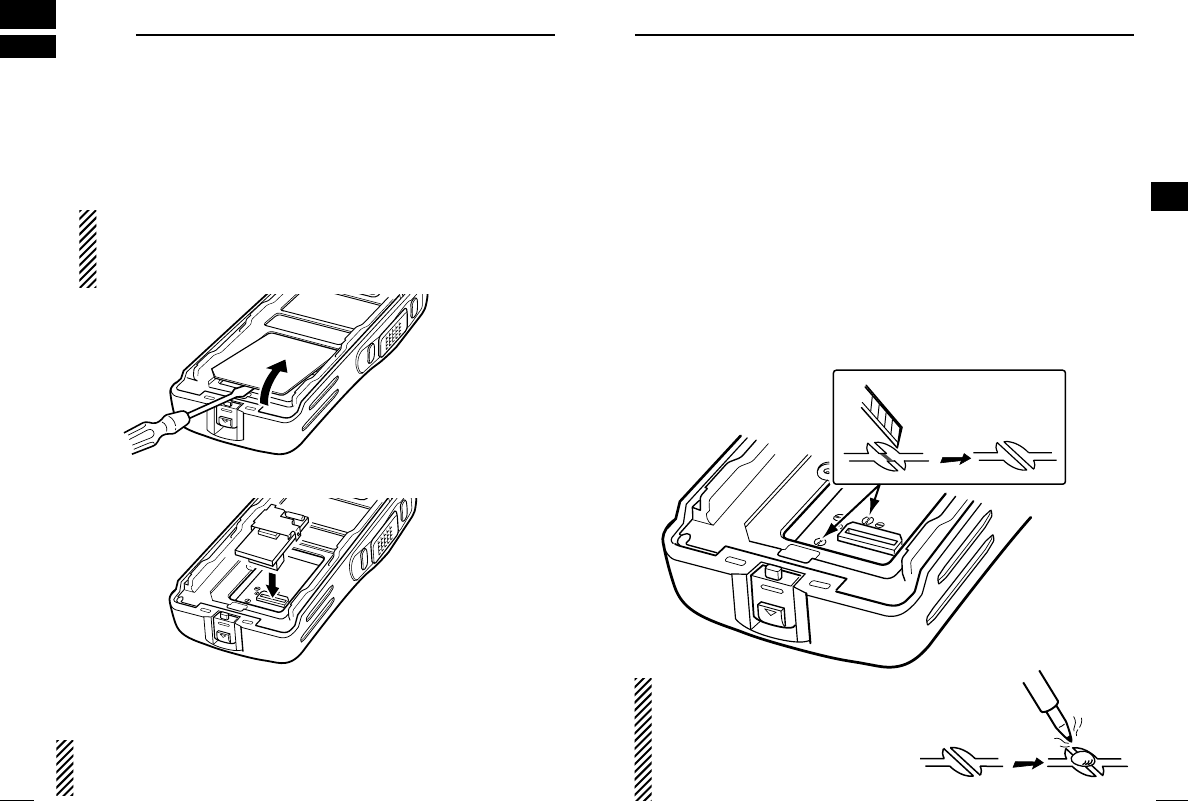
■Optional unit installation
Install the optional unit as follows:
qRotate [VOL] to turn the power OFF, and remove the battery
pack. (p. 3)
wRemove the unit cover.
NOTE: Use a flat head screw driver or a similar flat instru-
ment, and insert into the hollow of the chassis, then lift and
take away the unit cover. (The removed cover cannot be used
again.)
eInstall the unit as shown below.
rReplace the unit cover and the battery pack, then rotate [VOL] to
turn the power ON.
NOTE: The optional UT-109/UT-110
SCRAMBLER UNITS
requires
some PC board modifications. Please refer to the additional in-
stallation as at right.
*This illustration is
described with the
UT-110.
■Scrambler unit installation
The following PC board modification is required when installing the
optional UT-109 or UT-110.
qRotate [VOL] to turn the power OFF, and remove the battery
pack. (p. 3)
wRemove the unit cover as shown at left (Optional unit installation.)
eCut the pattern on the PCB at the TX mic circuit (MIC) and RX
AF circuit (DISC) as shown below.
rInstall the scrambler unit as shown at left (Optional unit installa-
tion.)
tReplace the unit cover and the battery pack, then rotate [VOL] to
turn the power ON.
NOTE: When uninstalling the
scrambler unit
Be sure to re-solder the discon-
nected points at left, otherwise no
TX modulation or AF output is
available.
!IC-F14_F24.qxd 04.6.17 6:22 PM Page 18 (1,1)

21
5
BATTERY CHARGING
5
20
5BATTERY CHARGING
■Battery charging
Prior to using the transceiver for the first time, the battery pack must
be fully charged for optimum life and operation.
CAUTION: To avoid damage to the transceiver, turn it OFF while
charging.
•Recommended temperature range for charging:
+10°C to +40°C (+50°F to +104°F)
- The Li-Ion battery functions within –20°C to +60°C (–4°F to
+140°F)
•Use the specified chargers (BC-119N, BC-121N and BC-160).
NEVER use another manufacturer’s charger.
•Use the optional AC adapter. NEVER use another manufacturer’s
AC adapter.
Recommendation:
Charge the supplied battery pack for a maximum of up to
10 hours. Li-Ion batteries are different from Ni-Cd batteries in
that it is not necessary to completely charge and discharge them
to prolong the battery life. Therefore, charging the battery in in-
tervals, and not for extended periods is recommended.
■Caution
RDANGER Charge the specified Icom batteries only.
Only tested and approved for use with genuine Icom batteries. Fire
and/or explosion may occur when a third party battery pack or
counterfeit product is charged.
CAUTION! NEVER insert battery pack/transceiver (with the bat-
tery pack attached) with wet or soiled into the charger. This may re-
sult in corrosion of the charger terminals or damage to the charger.
The charger is not waterproof and water can easily get into it.
NEVER incinerate used battery packs. Internal battery gas may
cause an explosion.
NEVER immerse the battery pack in water. If the battery pack be-
comes wet, be sure to wipe it dry immediately (particularly the bat-
tery terminals) BEFORE attaching it to the transceiver. Otherwise,
the terminals will become corroded, or cause connection failure,
etc.
NEVER short the terminals of the battery pack. Also, current may
flow into nearby metal objects, such as a necklace, etc. Therefore,
be careful when carrying with, or placing near metal objects, carry-
ing in handbags, etc.
AVOID leaving the battery pack in a fully charged, or completely
discharged condition for long time. It causes shorter battery life. In
case of leaving the battery pack unused for a long time, it must be
kept safely after discharge, or use the battery until the battery indi-
cator appears, then remove it from the transceiver.
If your battery pack seems to have no capacity even after being
charged, fully charge the battery pack again. If the battery pack still
does not retain a charge (or very little), a new battery pack must be
purchased.
!IC-F14_F24.qxd 04.6.17 6:22 PM Page 20 (1,1)
22
5BATTERY CHARGING
23
5
BATTERY CHARGING
5
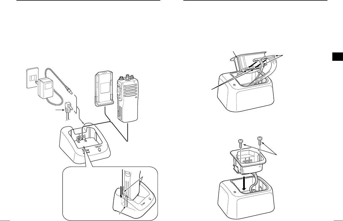
■Optional battery chargers
DRapid charging with the BC-160
The optional BC-160 provides rapid charging of optional Li-Ion bat-
tery packs.
• An AC adapter (may be supplied with BC-160 depending on ver-
sion) or the DC power cable (OPC-515L/CP-17L) is additionally
required.
AC adapter
(Not supplied with
some versions.)
Optional OPC-515L
(for 13.8 V power
source) or CP-17L
(for 12 V cigarette
lighter socket) can
be used instead of
the AC adapter.
BP-231 TRANSCEIVER
bc-160
IMPORTANT!:
Ensure the guide
lobs on the battery
pack are correctly
aligned with the
guide rails inside
the charger
adapter. Guide rail
Lobs
ïAD-106 installation
qInstall the AD-106 desktop charger adapter into the holder space
of the BC-119N/121N.
wConnect the plugs of the BC-119N/BC-121N to the AD-106 with
the connector, then install the adapter into the charger with the
supplied screws.
Desktop charger adapter
Connectors
Plugs
Screws supplied
with the charger
adapter
!IC-F14_F24.qxd 04.6.17 6:22 PM Page 22 (1,1)
25
5
BATTERY CHARGING
5
24
5BATTERY CHARGING
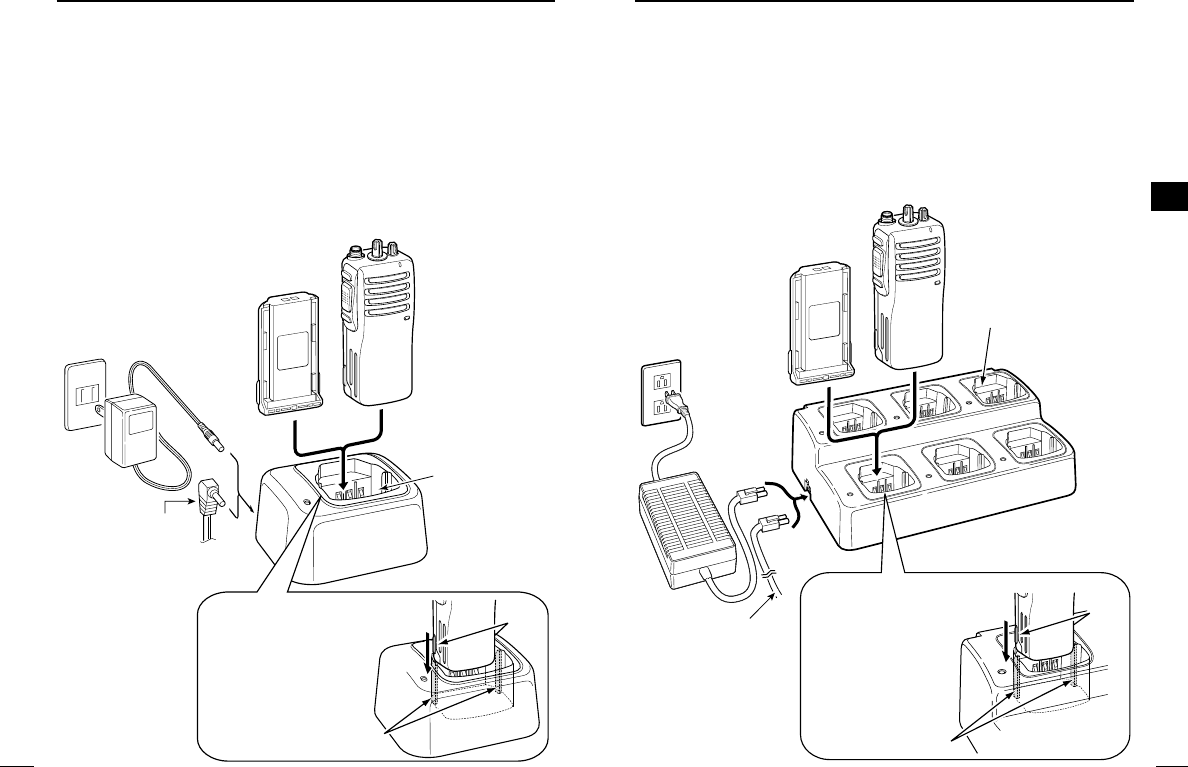
DRapid charging with the BC-119N+AD-106
The optional BC-119N provides rapid charging of optional Li-Ion
battery packs.
The following items are additionally required:
• One AD-106 (purchase separately).
• An AC adapter (may be supplied with BC-119N depending on ver-
sion) or the DC power cable (OPC-515L/CP-17L).
AD-106 charger
adapter is installed
in BC-119N.
AC adapter
(Not supplied with
some versions.)
Optional OPC-515L
(for 13.8 V power
source) or CP-17L
(for 12 V cigarette
lighter socket) can
be used instead of
the AC adapter.
BP-231
TRANSCEIVER
IMPORTANT!:
Ensure the guide
lobs on the battery
pack are correctly
aligned with the
guide rails inside
the charger
adapter.
Lobs
Guide rails
DRapid charging with the BC-121N+AD-106
The optional BC-121N allows up to 6 battery packs to be charged
simultaneously. The following items are additionally required.
• Six AD-106.
• An AC adapter (BC-124) or the DC power cable (OPC-656)
AC adapter
(Purchase
separately)
BP-231
AD-106 charger
adapters are installed
in each slot.
TRANSCEIVER
DC power cable
(OPC-656)
(Connect with the
DC power supply;
13.8 V/at least 7 A)
IMPORTANT!:
Ensure the guide
lobs on the
battery pack are
correctly aligned
with the guide
rails inside the
charger adapter.
Guide rails
Lobs
!IC-F14_F24.qxd 04.6.17 6:22 PM Page 24 (1,1)
27
6
SWIVEL BELT CLIP
6
26
6SWIVEL BELT CLIP
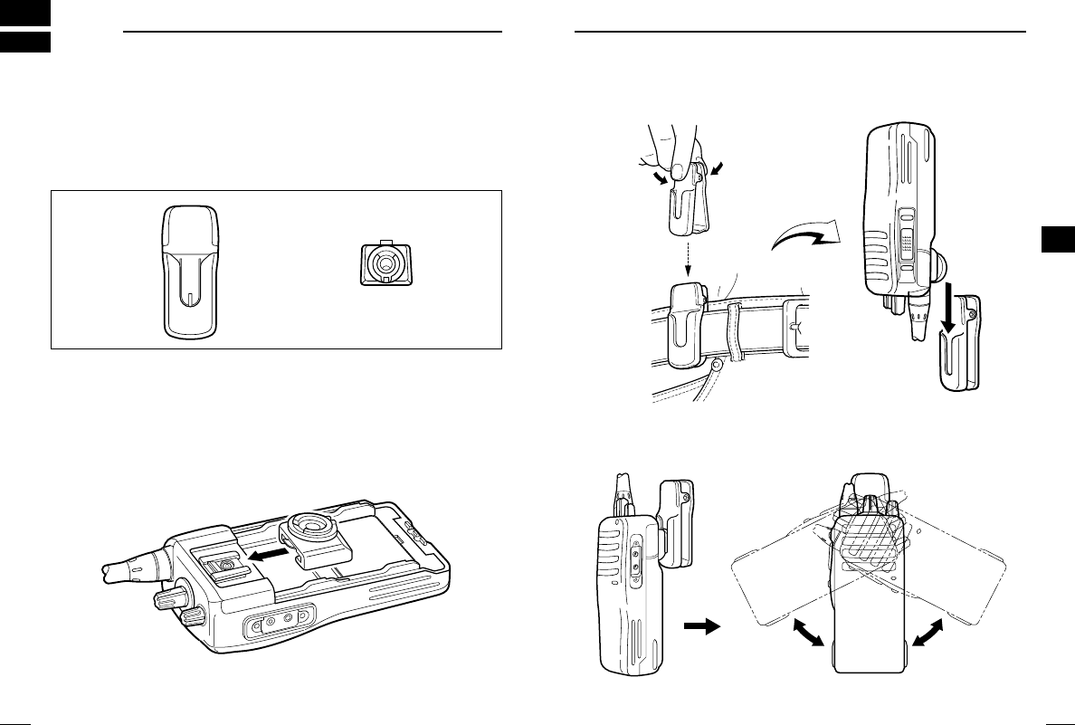
■MB-93 contents
Qty.
qBelt clip …………………………………………………………… 1
wBase clip …………………………………………………………… 1
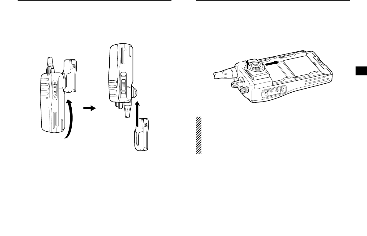
■To attach
qRelease the battery pack if it is attached. (p. 3)
wSlide the base clip in the direction of the arrow until the base clip
is locked and makes a ‘click’sound.
q w
eClip the belt clip to a part of your belt. And insert the transceiver
into the belt clip until the base clip inserted fully into the groove.
rOnce the transceiver is locked in place, it swivels as illustrated
below.
!IC-F14_F24.qxd 04.6.17 6:22 PM Page 26 (1,1)
29
6
SWIVEL BELT CLIP
6
28
6SWIVEL BELT CLIP
■To detach
qTurn the transceiver upside down in the direction of the arrow
and pull out from the belt clip.
wRelease the battery pack if it is attached. (p. 3)
ePinch the clip (q), and slide the base clip in the direction of the
arrow (w).
CAUTION:
HOLD THE TRANSCEIVER TIGHTLY, WHEN HANGING OR
DETACHING THE TRANSCEIVER FROM THE BELT CLIP.
Otherwise the transceiver may not be attached to the holder or
swivel properly if the transceiver is accidentally dropped and the
base clip is scratched or damaged.
qw
!IC-F14_F24.qxd 04.6.17 6:22 PM Page 28 (1,1)
31
7
SPEAKER-MICROPHONE
7
30
7SPEAKER-MICROPHONE
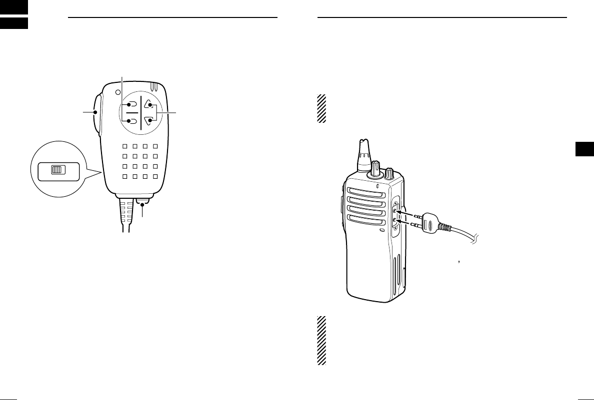
■Optional HM-75A description
A
B
OFF ON
LOCK
Earphone jack
PTT switch
Lock switch:
Locks all keys
except [PTT].
[Mic A]/[Mic B] keys*
[Mic Up]/[Mic Down] keys*
*The desired function
can be assigned
independently by
your dealer. (p. 9)
Rear
■To attach
Attach the connector of the speaker-microphone into the [SP MIC]
connector on the transceiver and tighten the screw.
CAUTION: When connecting the speaker-microphone to the
transceiver, make sure that power to the transceiver is turned
OFF, otherwise the CPU may malfunction.
IMPORTANT!: KEEP the [SP MIC] jack cover attached (trans-
ceiver) when the speaker-microphone is not in use (p. 4). Water
will not get into the transceiver even if the cover is not attached,
however, the terminals (pins) will become rusty, or the trans-
ceiver will function abnormally if the connector becomes wet.
To [SP MIC] connector
CAUTION: Attach the speaker-
microphone s connector securely
to prevent accidental dropping, or
water intrusion in the connector.
!IC-F14_F24.qxd 04.6.17 6:22 PM Page 30 (1,1)

33
8
OPTIONS
8
32
8OPTIONS
DBATTERY PACK
•BP-230 Li-Ion
BATTERY PACK
7.4 V/800 mAh Li-Ion battery pack, allows approx. 5.5 hours* op-
eration.
•BP-231 Li-Ion
BATTERY PACK
7.4 V/1150 mAh Li-Ion battery pack, allows approx. 8 hours* op-
eration. The same as supplied with the transceiver.
•BP-232 Li-Ion
BATTERY PACK
7.4 V/2000 mAh Li-Ion battery pack, allows approx. 14 hours* op-
eration.
*Typical operation; Tx:Rx:Stand-by duty cycle=5:5:90
DCHARGERS
•BC-119N
DESKTOP CHARGER
+ AD-106
CHARGER ADAPTER
+ BC-145
AC ADAPTER
For rapid charging of battery packs. An AC adapter is supplied
with the charger depending on versions. Charging time: approx. 2
hours when BP-231 is attached.
•BC-121N
MULTI
-
CHARGER
+ AD-106
CHARGER ADAPTER
(6 pcs.)
+ BC-124
AC ADAPTER
For rapid charging of up to 6 battery packs (six AD-106’s are re-
quired) simultaneously. An AC adapter should be purchased sep-
arately. Charging time: approx. 2 hours when BP-231 is attached.
•BC-160
DESKTOP CHARGER
+ BC-145
AC ADAPTER
For rapid charging of battery packs. An AC adapter is supplied
with the charger depending on versions. Charging time: approx. 2
hours when BP-231 is attached.
DOPTIONAL UNITS
•UT-108
DTMF DECODER UNIT
Provides pager and code squelch capabilities.
• UT-109 (#01)/UT-110 (#01)
SCRAMBLER UNITS
Non-rolling type (UT-109)/Rolling type (UT-110) voice scrambler
unit provides higher communication security.
• UT-113
MAN DOWN UNIT
Provides a measure of safety when working in a hazardous envi-
ronment, etc.
DBELT CLIPS
•MB-93
SWIVEL BELT CLIP
•MB-94
BELT CLIP
Exclusive alligator-type belt clip. The same as supplied with the
transceiver.
•MB-96*/96F
LEATHER BELT HANGER
*MB-93’s base clip is required.
DDC CABLES
•CP-17L
CIGARETTE LIGHTER CABLE
Allows charging of the battery pack through a 12 V cigarette
lighter socket. (For BC-119N)
•OPC-515L/OPC-656
DC POWER CABLES
Allows charging of the battery pack using a 13.8 V power source
instead of the AC adapter.
OPC-515L: For BC-119N
OPC-656 : For BC-121N
DOTHER OPTIONS
•SP-13
EARPHONE
Provides clear receive audio in noisy environment.
•HM-75A/HM-131L
SPEAKER
-
MICROPHONE
Combination speaker-microphone that provides convenient oper-
ation while hanging the transceiver from your belt.
HM-75A has the programmable function keys, Mic Up, Mic Down,
Mic A and Mic B.
HM-131L has a moisture proof construction.
•HS-94/HS-95/HS-97
HEADSET
+ VS-1L
VOX
/
PTT CASE
HS-94: Ear hook type HS-95: Neck-arm type
HS-97: Throat microphone
VS-1L: VOX/PTT switch box for hands-free operation, etc.
•FA-SC73US/FA-SC56VS/FA-SC57VS
STUBBY ANTENNAS
FA-SC73US: 450–490 MHz FA-SC56VS: 150–162 MHz
FA-SC57VS: 160–174 MHz
•FA-SC25U/FA-SC57U/FA-SC72U/FA-SC25V/FA-SC55V
ANTENNAS
FA-SC25U: 400–430 MHz FA-SC57U: 440–470 MHz
FA-SC72U: 470–520 MHz FA-SC25V: 136–155 MHz
FA-SC55V: 146–174 MHz (The same as supplied with the transceiver)
!IC-F14_F24.qxd 04.6.17 6:22 PM Page 32 (1,1)

1-1-32 Kamiminami, Hirano-ku, Osaka 547-0003, Japan
A-6369D-1EX
Printed in Japan
© 2004 Icom Inc.
!IC-F14_F24.qxd 04.6.17 6:22 PM Page 34 (1,1)