ICOM orporated 278000 Marine Radar User Manual MXR 5000R MXR 5000T Instruction Manual
ICOM Incorporated Marine Radar MXR 5000R MXR 5000T Instruction Manual
UserManual.wiki
>
ICOM orporated
>
278000 User Manual
>
Installation Manual
Contents
1.
Manual
2.
Installation Manual
Installation Manual
Navigation menu
Upload a User Manual
Namespaces
Wiki Guide
HTML
PDF
Info
Views
User Manual
Discussion / Help
Navigation
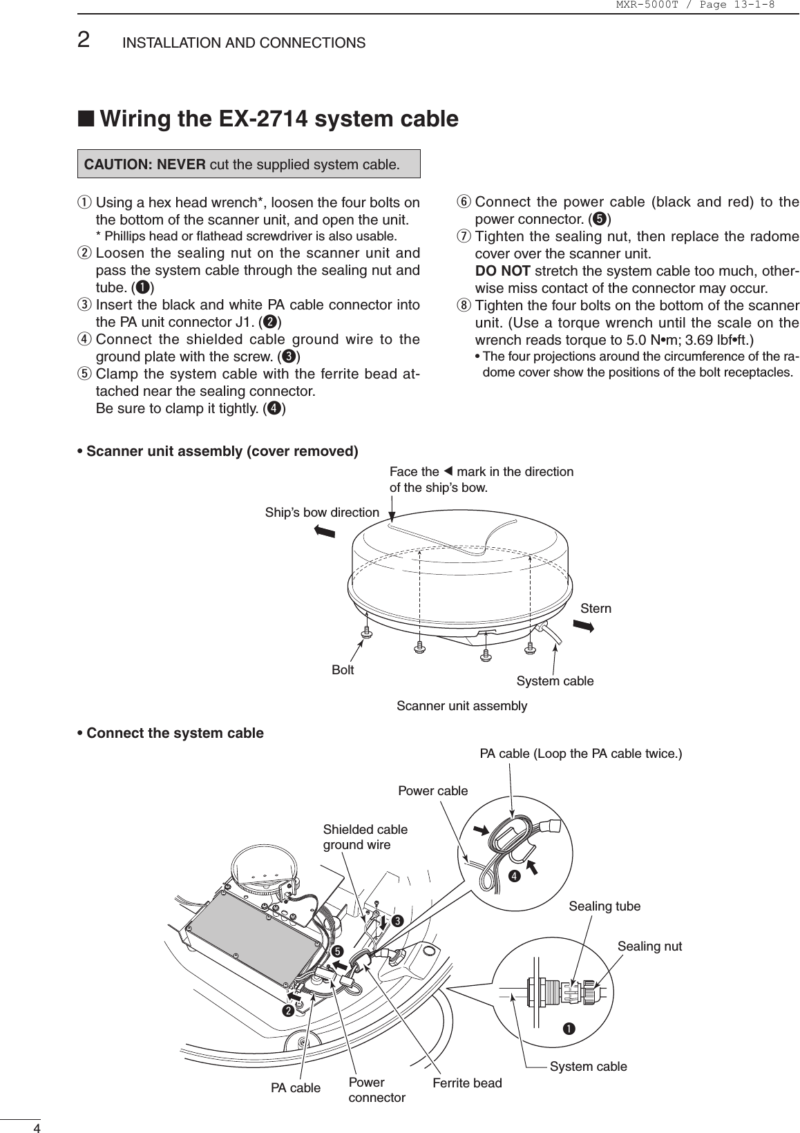
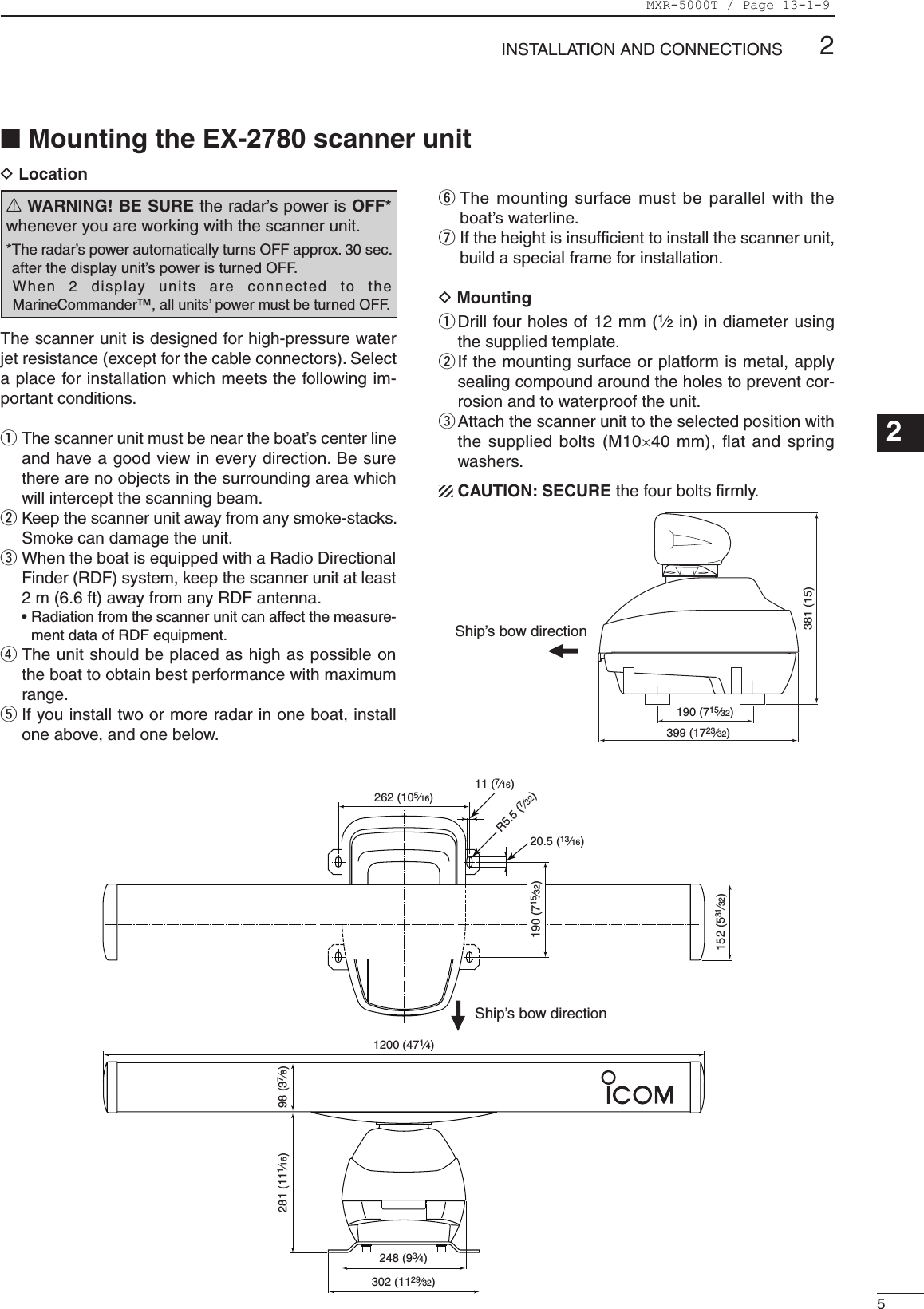
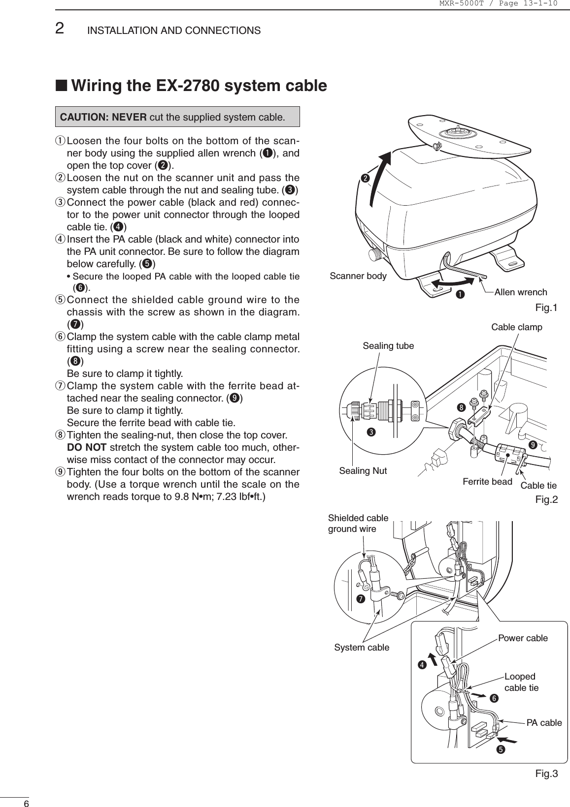
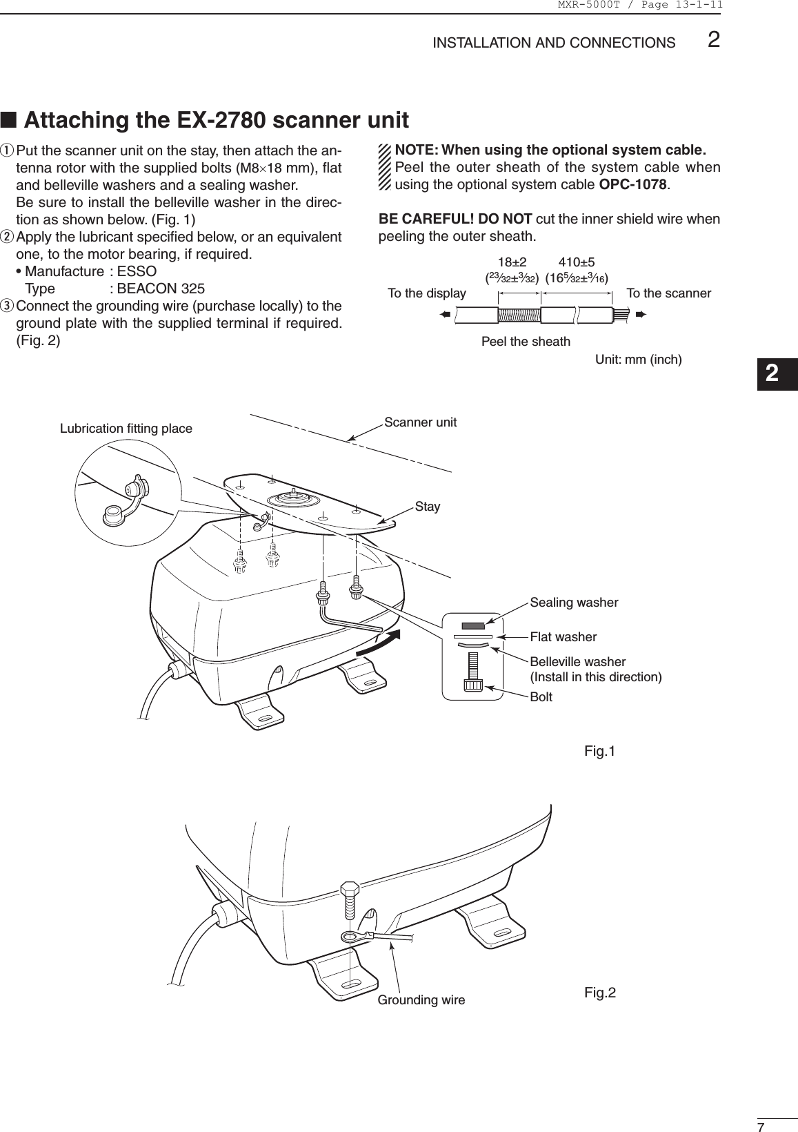
![22INSTALLATION AND CONNECTIONS■ ConnectionCAUTION: Before connecting, make sure discon-necting the radar unit’s DC power cable from the battery.12 V/24 VbatteryRadar unitKEEP the terminal guard attached after connecting cables. NOTE: Use the termi-nals as shown below for the cable connections.SolderCrimpTu rn the power OFF.GroundNEVER connect anything other than the supplied scanner unit.Supplied scanner unitMarineCommander™MXP-5000Te rminal guardGNDDC IN12V/24VNCDetach the terminal guard first.■ Power source requirementCAUTION: Before connecting the DC power cable, check the following important items. Make sure:• Output voltage of the power source is 12 V/24 V DC.• DC power cable polarity is correct. Red : Positive + terminal Black : Negative _ terminal• Fuse rating of the DC power cable is correct. (The 10 A fuse is pre-installed.) 5 A : For 24 V power source 10 A : For 12 V power source■ Ground connectionTo prevent electrical shocks and other problems, ground the radar unit through the [GND] terminal. For best results, connect a heavy gauge wire or strap to the nearest grounding point on the boat. The distance between the [GND] terminal and the ground point should be as short as possible.■ MountingFirst, drill four Ø5.5–6 mm (7⁄32–1⁄4") holes to mount the radar unit using the units base as a pattern.Mount the radar unit securely with the four supplied bolts (M5×30 mm) to a flat surface which supports more than approx. 5 kg (11 lb).CAUTION: KEEP the radar unit at least 1.8 meter (5.9 ft) away from your vessel’s magnetic naviga-tion compass.Flat washerFlat washerSpring washerSpring washerBoltNutMXR-5000T / Page 13-1-6](https://usermanual.wiki/ICOM-orporated/278000.Installation-Manual/User-Guide-1383047-Page-6.png)


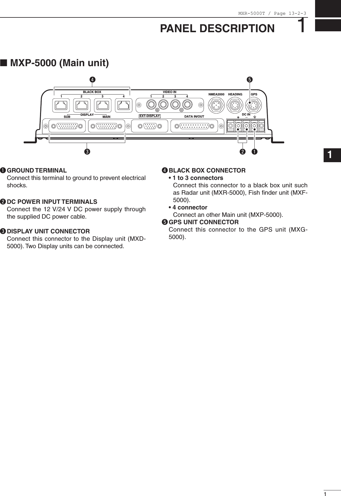
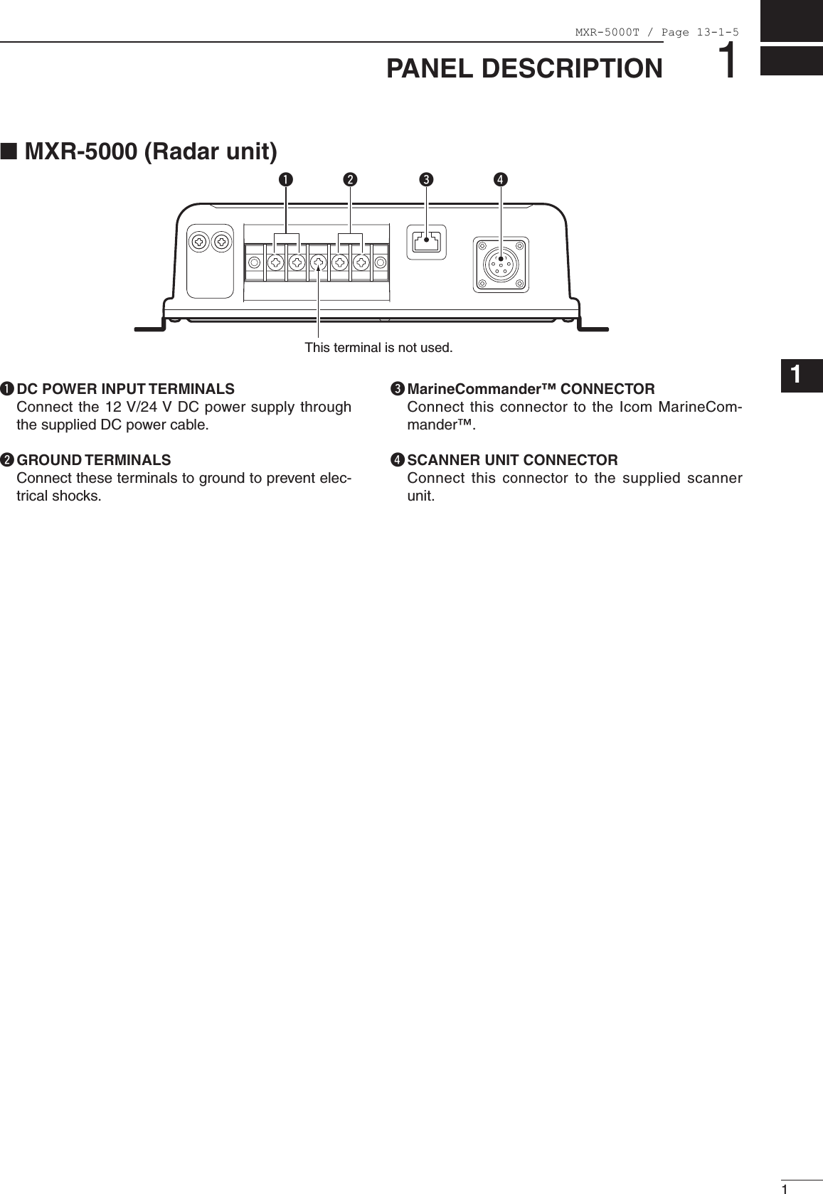
![21PANEL DESCRIPTIONq POWER/DISPLAY BLLIANCE SWITCH [ /BRILL]• While the MarineCommander’s power is OFF Push to turn ON the MarineCommander’s power.• While the MarineCommander’s power is ON ➥ Push to turn the Radar second menu. •DisplayBrilliance,RadarTXsetting,PanelBrilliantand Color Palette are available. •Pushtwoormoretimestoincreaseordecreasethe display brilliance. ➥ Hold down for 3 seconds to turn OFF the Mari-neCommander’s power.w WAYPOINT/MAN OVERBOARD SWITCH [WPT/MOB] ➥ Push to enter the Waypoint screen. •Waypointwindowappears. ➥ Hold down for 3 seconds to mark the man over-board point on the screen. When a crew mem-ber falls overboard. •MOBreadoutshowsthebearinganddistancetotheMOBpoint. •Push[MOB]for3secondstocancelthefunction. •Positionandbearingdataarenecessary.e RANGE UP/ DOWN SWITCHES [+]/[–] Push[+]or[–]tosetasuitablescreenrange.r FOCUS/DISPLAY LAYOUT SWITCH [FOCUS/LAYOUT] ➥ Push to change the selected screen. •Orangeboxindicatestheselectedscreen. ➥ Hold down for 3 seconds to enter the display se-lection screen.t UP, DOWN, LEFT, RIGHT KEYS [Ù Ú Ω ≈] Set the alarm area, ATA target, etc. according to the menu act. Usethe[Ù][Ú]toselectmenuitem. Pushingcenterofthe[Ù Ω]/[Ù ≈]or[Ú Ω]/[Ú ≈]allowsyoutomovethecrosslinecursortotheupper (or lower) left or right.y SUB MENU SWITCH [SUB] While entering the Menu screen, push to enter the Sub menu. u MENU SWITCH [MENU] Push to enter the Menu screen. i CLEAR SWITCH [CLEAR] Push to clear the current function. While entering the Menu screen, push to clear and return to the upper menu or clear the Menu screen. o SELECTION DIAL [DIAL] ➥ While entering Menu screen, rotate to select the Menu groups, items or options. ➥ Rotate to set the function level, such as Gain, SEA or Rain level. !0 ENTER SWITCH ➥ Push enter the Radar 1st menu. •Radar1stmenuincludestheGaincontrol,Sea,Rain, Radar TX menu and Heading line OFF func-tion. ➥ While entering Menu screen, push enter the se-lected menu or function.PUSH TO ENTERMENUWPTFOCUSLAYOUTMOBCLEARSUBBRILLRANGEqwertyuio!0■MXD-5000(Displayunit)MXR-5000T / Page 13-2-4](https://usermanual.wiki/ICOM-orporated/278000.Installation-Manual/User-Guide-1383047-Page-20.png)
![4BASIC OPERATION3■TurningpowerON/OFFq Push[ ]toturnthepowerON. •TheinitialscreenandWARNINGscreensappear.w Push[ENTER]tostartoperation. •Thewarmingupscreenappears. •The magnetron inside the scanner unit warms up for 90 seconds.e When the warming up is complete, the operating screen appears to start operation.r Push[BRILL],andthen[u],toselecttheRadarTXmenu. t Rotate[DIAL]toselect“TX,”thenpush[ENTER]tostart scanning. •Targetsandheadingmarkerappear. •Thescreenappearsapproximately2secondsafterpushing[ENTER],when“Auto”isselectedinthe“TUNE”ofthe“Gain”menu. Repeat step r and t,andselect“STBY,”thenpush[ENTER]toreturntothestand-bymodeofthe Scanner transmission.y Holddown[ ]for3secondstoturnthepowerOFF. q If any other than Radar screen appears, hold down[LAYOUT](FOCUS)for2secondstoenterthe screen selection mode.w Rotate [DIAL] to select Radar, then push[ENTER].MXR-5000T / Page 13-2-6](https://usermanual.wiki/ICOM-orporated/278000.Installation-Manual/User-Guide-1383047-Page-22.png)
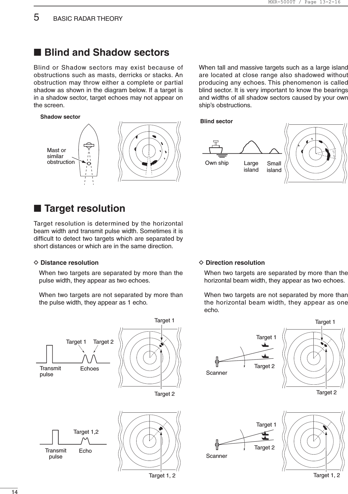
![53BASICOPERATION123456789101112131415161718192021q Turn the power ON.w Turn the Radar TX ON. •See“TurningpowerON/OFF”onpageatleft.e Push[+]or[–]oneormoretimestoselectthedisplay range. •Thescreenrangereadoutshowsthemaximumrangeof the screen.r Push[ENTER]toentertheRadarsettingmenu,thenrotate[DIAL]tosetthegainlevelontheGainmenu. •Clockwiserotationincreasesthegain. •Increasedgainmayincreasescreennoise.tPush[ENTER],andthen[u]oncetoselecttheSea menu, to set the sensitivity time control, rotate[DIAL]counterclockwisetosettheSEAtominimum.y Push[ENTER],andthen[u]twicetoselecttheRain menu, to set the rain clutter control, then rotate[DIAL]counterclockwisetosetRAINtominimum.u Select Radar Display mode. ➥ Push[MENU],thenrotate[DIAL]untilthe“RadarDisplayMode”menubecomeshighlighted. ➥ Push[ENTER],thenrotate[DIAL]toselectoneof Head-up; H-UP, North-up; N-UP, Course-up; C-UP or True Motion; TM screens. ➥Push[ENTER],andthen[CLEAR]twice,toexitthe menu screen.CAUTION: When setting of the SEA to a fully clockwise position, close targets are blanked.DHeadingmarkerThe heading marker is a line that shows your ship’s bow direction. (This marker will appear in the center of the screen when the Head-up screen H UP is selected.) The heading marker can be hidden when the desired target is located under the heading marker.•Push[ENTER]toentertheRadarmenu,thenpush[u]four times to select the Heading marker menu. Hold down [ENTER]tohidetheheadingmarker.Release[ENTER]toreturn.DFixedrangeringsThe fixed range rings can be used for rough distance measurement.➥ Push[MENU],thenrotate[DIAL]untilthe“Presentation”menubecomeshighlighted.➥ Push[ENTER],thenrotate[DIAL]untilthe“Ring”menu becomes highlighted. ➥ Push[ENTER],thenrotate[DIAL]toselectoneof Ring-OFF; OFF or any other three Ring levels; Low, Mid, High.➥Push[ENTER],andthen[CLEAR]twice,toexitthemenu screen.DManualtuningThe receiver tuning can be manually adjusted. ➥ Push[MENU],andthen[ENTER],toentertheGainmenu.Thenrotate[DIAL]untilthe“Tune”menu becomes highlighted. ➥ Push[ENTER],thenrotate[DIAL]toselectthe“Manual...”menuandpush[ENTER]toturnthemanualtuninglevelindicator,thenrotate[DIAL]tosetthe“TuneLevel”metertothemaximumlevel.➥Push[ENTER]toexitthemanualtuningscreen.DBrillianceadjustmentThe intensity of the screen can be adjusted. When you require continuous operation, but not constant viewing, a lower setting can increase the life of the LCD display. •KeyilluminationThe backlighting of the keys can be adjusted for convenient operation.Push[BRILL],andthen[u]threetimes,tocallupthe“PanelBrill”menu.Thenrotate[DIAL]toselecttheil-lumination level.NOTE: Manual adjustment can be used. (See below.)MENUWPTFOCUSLAYOUTMOBCLEARSUBBRILLRANGEu[ENTER][CLEAR][MENU][�][LAYOUT] [+] or [–](RANGE)[ ]■BasicoperationYou can automatically set SEA control. ➥ Push[MENU],thenrotate[DIAL]untilthe“Gain”menu becomes highlighted. ➥ Push[MENU],thenrotate[DIAL]untilthe“AutoSea”menubecomeshighlighted.➥ Push[ENTER],thenrotate[DIAL]toselect“ON.”➥Push[ENTER],andthen[CLEAR]twice,toexitthemenu screen.MXR-5000T / Page 13-2-7](https://usermanual.wiki/ICOM-orporated/278000.Installation-Manual/User-Guide-1383047-Page-23.png)
![63BASICOPERATION This function eliminates reflection echoes from rain, snow, fog etc. qPush[MENU],andthen[ENTER],toentertheGain menu.wRotate[DIAL]untilthe“Rain...”menubecomeshighlighted.ePush[ENTER]toturntheRainlevelindicator.rRotate[DIAL]toadjusttheRainlevel. •NOTE: DO NOT reduce the reflection echoes too much, otherwise you may miss weaker targets. tPush[ENTER]toexittheRainadjustmentscreen. This function serves to eliminate echoes from waves at close range. Reduce the receiver gain for close objects within a radius of 8 miles to eliminate sea clutter.qPush[MENU],andthen[ENTER],toentertheGain menu.wRotate[DIAL]untilthe“Sea...”menubecomeshighlighted.ePush[ENTER]toturntheSEAlevelindicator.rRotate[DIAL]toadjustSEAlevel.tPush[ENTER]toexittheSEAadjustmentscreen. The scanning area can be shifted in a desired direction and can be enlarged partially. This is useful when the Head-up* is selected and you want to enlarge the bow direction display, or, the center of the screen shifts in the direction of the intersection. qPush[MENU]toentertheMenuscreen.wRotate[DIAL]untilthe“CenterShift”menubecomes highlighted.ePush[ENTER]thenrotate[DIAL]toselectthe“ON...”option.rPush[ENTER]toactivatetheCenterShiftfunction. •TheCursorwindowappearsintheupperrightofthescreen. •Thisfunctionisavailablefor24NMorshorterrangeselection. *This function is not available in the TM screen.tPush[Ù Ú Ω ≈] to move the cursor where you want to shift the center of the screen. •Max.offsettingisupto75%ofthescreen.yPush[ENTER]toshiftthescreen.The following are typical basic operation examples, which may hinder radar reception (sea clutter, precipitation interference and echoes from other radar).■RAINfunction(MENU w Gain u Rain...)WARNING: The SEA function reduces the receiver sensitivity of objects within 8 miles. Therefore, caution and careful adjustment are necessary when using the SEA function. Small objects may not be displayed on the screen when strong echoes from the rain or the island within 1 NM while automatic SEA function is activating.Adjust RAIN controlSmall echosWith OFF CENTER ONNormal screen■SEAfunction (MENU w Gain u Sea...)Adjust SEA controlEchos from sea waves■CENTERSHIFTfunction MENU w CenterShiftMXR-5000T / Page 13-2-8](https://usermanual.wiki/ICOM-orporated/278000.Installation-Manual/User-Guide-1383047-Page-24.png)
![73BASICOPERATION123456789101112131415161718192021 The ZOOM function expands the target to two times normal size.qPush[MENU]toentertheMenuscreen.wRotate[DIAL]untilthe“Zoom”menubecomeshighlighted.ePush[ENTER]thenrotate[DIAL]toselectthe“ON...”option.rPush[ENTER]toactivatetheZoomfunction. •TheZoom window appearsinthelowerleftofthescreen. t Push[Ù Ú Ω ≈]tomovethedottedboxtothedesired target.yPush[ENTER]tosetthezoomposition.■IRfunction (MENU w Radar Setup u Signal Process u IR) Radar interference may appear when another ship’s radar is operating on the same frequency band in close proximity. The IR function can eliminate this type of interference. qPush[MENU]toentertheMenuscreen.wRotate[DIAL]untilthe“RadarSetup”menubecomes highlighted.ePush[ENTER]thenrotate[DIAL]untilthe“SignalProcess”menubecomeshighlighted.rPush[ENTER]thenrotate[DIAL]untilthe“IR”menu becomes highlighted.tPush[ENTER]thenrotate[DIAL]toselecttheIRfunction,1,2orOFF.Push[ENTER]. •“IR1”or“IR2”appearsintheupperleftofthescreen,when the function is activated. ■STRETCHfunction (MENU w Radar Setup u Signal Process u Stretch) The blips can be magnified electronically for easier viewing of small targets. qPush[MENU]toentertheMenuscreen.wRotate[DIAL]untilthe“RadarSetup”menubecomes highlighted.ePush[ENTER]thenrotate[DIAL]untilthe“SignalProcess”menubecomeshighlighted.rPush[ENTER]thenrotate[DIAL]untilthe“Stretch”menu becomes highlighted.tPush[ENTER]thenrotate[DIAL]toturnthefunctionON.Push[ENTER]. •“ES”appearsintheupperleftofthescreen,whenthefunction is activated. NOTE: Turn OFF this function during normal opera-tion. With STRETCH ONNormal screen■ZOOMfunction (MENU w Zoom)With IR function ONRadar interferenceMXR-5000T / Page 13-2-9](https://usermanual.wiki/ICOM-orporated/278000.Installation-Manual/User-Guide-1383047-Page-25.png)
![83BASICOPERATIONThe trails function memorizes echoes continuously or at constant intervals. This is useful for watching other ships’ tracks, approx. relative speed, etc. Trail time•Settingthetrailintervaltime (MENU w Trail u Trail Setup u Trail Time)qPush[MENU]toentertheMenuscreen.wRotate[DIAL]untilthe“Trail”menubecomeshighlighted.ePush[ENTER]thenrotate[DIAL]untilthe“TrailSetup”menubecomeshighlighted.rPush[ENTER]thenrotate[DIAL]untilthe“TrailTime”menubecomeshighlighted.tPush[ENTER]thenrotate[DIAL]toselectadesiredtrailintervaltime.Push[ENTER]. •6seconds,15seconds,30seconds,1minute,3min-utes, 6 minutes, 15 minutes, 30 minutes and ∞ (con-tinuous) are selectable.y Push[CLEAR]threetimestoexitthemenuscreen.•Settingthetrailcolor (MENU w Trail u Trail Setup u Trail Color)qPush[MENU]toentertheMenuscreen.wRotate[DIAL]untilthe“Trail”menubecomeshighlighted.ePush[ENTER]thenrotate[DIAL]untilthe“TrailSetup”menubecomeshighlighted.rPush[ENTER]thenrotate[DIAL]untilthe“TrailColor”menubecomeshighlighted.tPush[ENTER]thenrotate[DIAL]toselectadesiredtrailcolor.Push[ENTER]. •Blue,Yellow,Green,Red,Orange,WhiteandMulti(mixed color) are selectable.y Push[CLEAR]threetimestoexitthemenuscreen.•UsingtheTRAILSfunction(MENU w Trail u Trail)qPush[MENU]toentertheMenuscreen.wRotate[DIAL]untilthe“Trail”menubecomeshighlighted.ePush[ENTER]thenrotate[DIAL]untilthe“Trail”menu becomes highlighted.rPush[ENTER]thenrotate[DIAL]toselectthetrailfunctionON.Push[ENTER]. •“TRAILS”andtrailintervaltimeappearsintheupperleft of the screen. •Trailintervalcounterstartstocountuptothetrailtime.t All displayed echoes at the plotted time are memorized and displayed with a graduated intensity together with the current echoes. •Echoesaredisplayedwithminimumintensitywhen“∞”is selected.y To cancel the trail function, repeat steps q to r and select OFF. •“TRAILS”andtrailintervaltimedisappears.■TRAILSfunction (MENU w Trail)MXR-5000T / Page 13-2-10](https://usermanual.wiki/ICOM-orporated/278000.Installation-Manual/User-Guide-1383047-Page-26.png)
![93BASICOPERATION123456789101112131415161718192021To magnify the blips for easier viewing of small targets, the long pulse and echo stretch functions are available. When the long pulse is used in the 3⁄4 to 2 NM range, this function magnifies target echoes to the backward direction of the target. •PulseselectionqPush[MENU]toentertheMenuscreen.wRotate[DIAL]untilthe“RadarSetup”menubecomes highlighted.ePush[ENTER]thenrotate[DIAL]untilthe“SignalProcess”menubecomeshighlighted.rPush[ENTER]thenrotate[DIAL]untilthe“Pulse”menu becomes highlighted.tPush[ENTER]thenrotate[DIAL]toselectadesiredpulsetype,“Short”or“Long.”Push[ENTER].y Push[CLEAR]threetimestoexitthemenuscreen. •“SP”or“LP”appearsintheupperleftofthescreen.NOTE: Select“Short”thisfunctionduringnormaloperation. This function reduces the target distance resolution. ■Longpulsefunction (MENU w Radar Setup u Signal Process u Pulse)qPush[MENU]toentertheMenuscreen.wRotate[DIAL]untilthe“Presentation”menubecomes highlighted.ePush[ENTER]thenrotate[DIAL]untilthe“PPIArea”menubecomeshighlighted.rPush[ENTER]thenrotate[DIAL]toselectadesiredareasize,“Nar”or“Wide.”Push[ENTER].t Push[CLEAR]twicetoexitthemenuscreen.■PPIareaselection (MENU w Presentation u PPI Area)qPush[MENU]toentertheMenuscreen.wRotate[DIAL]untilthe“Presentation”menubecomes highlighted.ePush[ENTER]thenrotate[DIAL]untilthe“EchoColor”menubecomeshighlighted.rPush[ENTER]thenrotate[DIAL]toselectadesiredechocolor,“Yellow-Black,”“Green-Black,”“Red-Black,”“Multi-Black,”“Yellow-DarkBlue,”“Green-DarkBlue,”“Multi-DarkBlue,”“Green-White”or“Multi-White.”Push[ENTER].t Push[CLEAR]twicetimestoexitthemenuscreen.■EchoColorselection (MENU w Presentation u Echo Color)MXR-5000T / Page 13-2-11](https://usermanual.wiki/ICOM-orporated/278000.Installation-Manual/User-Guide-1383047-Page-27.png)
![410DISTANCE AND DIRECTION MEASUREMENTS■DistancemeasurementTYPE DESCRIPTIONRINGDisplays fixed rings.Suitable for rough estimations from your own ship to any target.VRM1Displays a variable range marker and activatedbythe[DIAL]fortherangemarker selector. Suitable for accurate measurements from your own ship to a target.VRM2Normally functions the same as VRM1. WhentheVRM1andEBL1selectsatarget, the center of VRM2 appears at the intersection point.Suitable for accurate measurements from target to target. Two measurement procedures are available with this radar. Operating them separately or jointly is possible. The Distance unit, nautical mile (nm), seemeile (sm) orkilometer(km)isselectedinthe“InitialSetting...”inthe“General”menuofthe“Systemsetup”menu.DUsingthexedringsqPush[MENU]toentertheMenuscreen.wRotate[DIAL]untilthe“Presentation”menubecomes highlighted.ePush[ENTER]thenrotate[DIAL]untilthe“Ring”menu becomes highlighted.rPush[ENTER]thenrotate[DIAL]toselecttheRINGfunctionON,either“Low,”“Mid”or“High.”Push[ENTER]todisplaythefixedring. •Theringrangeisxeddependingonthescreenrange.(See below.)t Push[CLEAR]twiceexitthemenuscreen.y Toclearthefixedrings,select“OFF”instepr above. Range (nm)Ring (nm)1 1.5 23468121624323648*1⁄81⁄41⁄23⁄4224343 434344444341122346812121⁄16 1⁄81⁄81⁄41⁄41⁄21⁄2NOTE: When the screen is shifted, the number of rings may differ.*Available for the MXR-5000T only.MXR-5000T / Page 13-2-12](https://usermanual.wiki/ICOM-orporated/278000.Installation-Manual/User-Guide-1383047-Page-28.png)
![114DISTANCE AND DIRECTION MEASUREMENTS123456789101112131415161718192021DUsingthevariablerangemarker qPush[MENU]toentertheMenuscreen.wRotate[DIAL]untilthe“EBL/VRM”menubecomeshighlighted.ePush[ENTER]thenrotate[DIAL]untilthe“VRM1...”menu(or“EBL1...”menu)becomeshighlighted.rPush[ENTER]thenrotate[DIAL]tosetthemarker. •Theyellowdottedcircleappears.(Oryellowdottedlineappears.) •Therangebetweentheshipandthetargetisdisplayedin the VRM1 readout. (Or the degree between the ship andtargetisdisplayedintheEBL1readout.)tPush[ENTER]. •Theyellowdottedcirclebecomesreddottedcircle.(Oryellow dotted line becomes red dotted line.)yRotate[DIAL]untilthe“VRM2...”menu(or“EBL2...”menu)becomeshighlighted.uPush[ENTER]thenrotate[DIAL]tosetthemarker. •Theyellowdottedcircleappears.(Oryellowdottedlineappears.) •Therangebetweentheshipandthetargetisdisplayedin the VRM2 readout. (Or the degree between the ship andtargetisdisplayedintheEBL2readout.)iPush[ENTER]. •Theyellowdottedcirclebecomesreddottedcircle.o Push[CLEAR]twiceexitthemenuscreen.MXR-5000T / Page 13-2-13](https://usermanual.wiki/ICOM-orporated/278000.Installation-Manual/User-Guide-1383047-Page-29.png)
![512BASIC RADAR THEORY■IndirectechoesIndirect echoes may be returned from either a passing ship, or returned from a reflecting surface, such as a mast on your own ship.An indirect echo from a reflecting surface will appear on a different bearing from the direct (true) echo, but the distance will be approximately the same for both.■Side-lobeechoesRadiation can escape on each side of the beam inside the lobes. If a target reflects this radiation, it will be displayed on the screen as an echo. Side-lobe echoes usually occur at short ranges and as a result of large (strongly reflective) targets. They canbereducedwithproperadjustmentofthe[SEA]control. Radarusesaformofelectromagneticradiation,whichlikelight,canbereected.Becauseofthisproperty,someobjects may cause false echoes on the screen where in fact no targets actually exist. These echoes may appear if a large vessel, bridge, or tank is in proximity. Operators should be familiar with the effects of these phenomena. In some cases, echoes can be reduced. Indirect echoTr ue echoTargetScannerMast orsimilar obstructionAn echo is reflected at this point.Own shipTargetBridgeMain beamSide lobesTr ue echoFalse echoFalseechoesTr ueechoMXR-5000T / Page 13-2-14](https://usermanual.wiki/ICOM-orporated/278000.Installation-Manual/User-Guide-1383047-Page-30.png)
![135BASICRADARTHEORY■MultipleechoesMultiple echoes may appear when a short-range and strong echo is received from a ship, bridge, or breakwater. Multiple echoes will appear beyond the target’s true echo point on the same bearing of a large target. They can be reduced with proper adjustment of the [SEA]control.■MinimumrangeDetection at short range is very important. Minimum range is determined primarily by transmitter pulse length, vertical beam width and height of the scanner unit. The shorter the transmission time, the quicker the return echoes can be received and their distance measured. The ability to see targets very close to the ship is decreased if the scanner is mounted too high off the water, because the bottom of the vertical beam of the scanner cuts off nearby targets.This target can not be recognized with radar.The target in this area can not be recognized.Pulse lengthPulse starting pointVertical beam widthOwn ship Another shipTr ue echoFalse echoes123456789101112131415161718192021MXR-5000T / Page 13-2-15](https://usermanual.wiki/ICOM-orporated/278000.Installation-Manual/User-Guide-1383047-Page-31.png)