ICOM orporated 280401 UHF Transceiver User Manual IC F70 F80
ICOM Incorporated UHF Transceiver IC F70 F80
Users Manual

INSTRUCTION MANUAL
This device complies with Part 15 of the FCC Rules. Operation is
subject to the condition that this device does not cause harmful
interference.
iF70DT/DS
VHF TRANSCEIVER
iF70T/S
iF80DT/DS
UHF TRANSCEIVER
iF80T/S
!IC-F70_F80.qxd 04.11.9 0:01 PM Page a (1,1)

i
EXPLICIT DEFINITIONS
WORD DEFINITION
RWARNING Personal injury, fire hazard or electric shock
may occur.
CAUTION Equipment damage may occur.
NOTE If disregarded, inconvenience only. No risk
of personal injury, fire or electric shock.
READ ALL INSTRUCTIONS carefully and com-
pletely before using the transceiver.
SAVE THIS INSTRUCTION MANUAL — This
instruction manual contains important operating instructions
for the IC-F70DT/F70DS/F70T/F70S VHF TRANSCEIVER
and IC-F80DT/F80DS/F80T/F80S UHF TRANSCEIVER.
IMPORTANT
Icom, Icom Inc. and the logo are registered trademarks of Icom
Incorporated (Japan) in the United states, the United Kingdom, Germany,
France, Spain, Russia and/or other countries.
All other products or brands are registered trademarks or trademarks of their
respective holders.
ABOUT APCO PROJECT 25
This device made under license under one or more of the fol-
lowing US patents: #4,590,473, #4,636,791, #5,148,482,
#5,185,796, #5,271,017, #5,377,229.
The IMBE™ voice coding Technology embodied in this prod-
uct is protected by intellectual property rights including patent
rights, copyrights and trade secrets of Digital Voice Systems,
Inc. This voice coding Technology is licensed solely for use
within this Communications Equipment. The user of this
Technology is explicitly prohibited from attempting to decom-
pile, reverse engineer, or disassemble the Object Code, or in
any other way convert the Object Code into a human-readable
form. U.S. Pat. Nos. #5,870,405, #5,826,222, #5,754,974,
#5,701,390, #5,715,365, #5,649,050, #5,630,011, #5,581,656,
#5,517,511, #5,491,772, #5,247,579, #5,226,084, #5,195,166.
!IC-F70_F80.qxd 04.11.9 0:01 PM Page i (1,1)

ii
RCAUTION! NEVER hold the transceiver so that the
antenna is very close to, or touching exposed parts of the
body, especially the face or eyes, while transmitting. The
transceiver will perform best if the microphone is 2 to 4 in. (5
to 10 cm) away from the lips and the transceiver is vertical.
RCAUTION! NEVER operate the transceiver with a
headset or other audio accessories at high volume levels.
RCAUTION! NEVER short the terminals of the bat-
tery pack.
DO NOT push PTT when not actually desiring to transmit.
AVOID using or placing the transceiver in direct sunlight or
in areas with temperatures below +22°F (–30°C) or above
+140°F (+60°C).
The basic operations, transmission and reception of the trans-
ceiver are guaranteed within the specified operating temper-
ature range. However, the LCD display may not be operate
correctly, or show an indication in the case of long hours of
operation, or after being placed in extremely cold areas.
DO NOT modify the transceiver for any reason.
KEEP the transceiver from the heavy rain, and Never
immerse it in the water. The transceiver construction is water
resistant, not waterproof.
The use of non-Icom battery packs/chargers may impair
transceiver performance and invalidate the warranty.
For U.S.A. only
CAUTION: Changes or modifications to this transceiver, not
expressly approved by Icom Inc., could void your authority to
operate this transceiver under FCC regulations.
PRECAUTION
!IC-F70_F80.qxd 04.11.9 0:01 PM Page ii (1,1)

iii
TABLE OF CONTENTS
IMPORTANT .................................................................................... i
EXPLICIT DEFINITIONS ................................................................. i
ABOUT APCO PROJECT 25 ........................................................... i
PRECAUTION ................................................................................. ii
TABLE OF CONTENTS .................................................................. iii
1 ACCESSORIES ..................................................................... 1–3
■Supplied accessories ............................................................. 1
■Accessory attachments .......................................................... 1
2 PANEL DESCRIPTION ......................................................... 4–7
■Front panel ............................................................................. 4
■Function display ..................................................................... 6
■Programmable function keys .................................................. 7
3 BASIC OPERATION .......................................................... 12–18
■Turning power ON ................................................................ 12
■Channel selection ................................................................. 12
■Call procedure ...................................................................... 13
■Receiving and transmitting ................................................... 13
■User set mode ...................................................................... 17
■Scrambler function ............................................................... 18
4 BIIS OPERATION .............................................................. 19–29
■Default setting ...................................................................... 19
■Receiving a call .................................................................... 19
■Transmitting a call ................................................................ 21
■Receiving a message ........................................................... 23
■Transmitting a status ............................................................ 25
■Transmitting an SDM (Short Data Message) ........................ 26
■Position data transmission ................................................... 27
■Printer connection ................................................................ 28
■Digital ANI ............................................................................ 28
■Auto emergency transmission .............................................. 28
■Stun function ........................................................................ 28
■BIIS indication ...................................................................... 29
■Priority A channel selection .................................................. 29
5 OPTIONAL UNIT INSTALLATION .................................... 30–31
■Optional unit installation ....................................................... 30
■UT-111 installation ................................................................ 31
6 BATTERY CHARGING ...................................................... 32–34
■Battery charging ................................................................... 32
■Battery caution ..................................................................... 32
■Optional battery chargers ..................................................... 33
7 OPTIONAL BATTERY CASE .................................................. 35
■Optional battery case ........................................................... 35
8 SWIVEL BELT CLIP .......................................................... 36–37
■MB-93 contents .................................................................... 36
■To attach ............................................................................... 36
■To detach .............................................................................. 37
9 SPEAKER-MICROPHONE ...................................................... 38
■Optional HM-138 description ................................................ 38
■Attachment ........................................................................... 38
10 OPTIONS ........................................................................... 39–40
11 SAFETY TRAINING INFORMATION ...................................... 41
!IC-F70_F80.qxd 04.11.9 0:01 PM Page iii (1,1)
1
1
ACCESSORIES
1
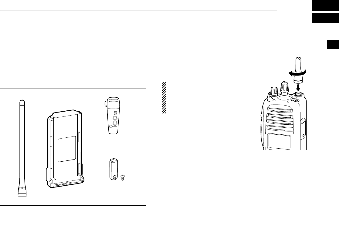
■Supplied accessories
The following accessories are supplied: Qty.
qFlexible antenna ……………………………………………1
wBattery pack …………………………………………………1
eBelt clip ………………………………………………………1
rJack cover (with screws) ………………………………1 set
■Accessory attachments
DFlexible antenna
Connect the supplied flexible anten-
na to the antenna connector.
CAUTION!
• NEVER HOLD by the antenna
when carrying the transceiver.
• Transmitting without an antenna
may damage the transceiver.
qwe
r
!IC-F70_F80.qxd 04.11.9 0:01 PM Page 1 (1,1)
2
1ACCESSORIES
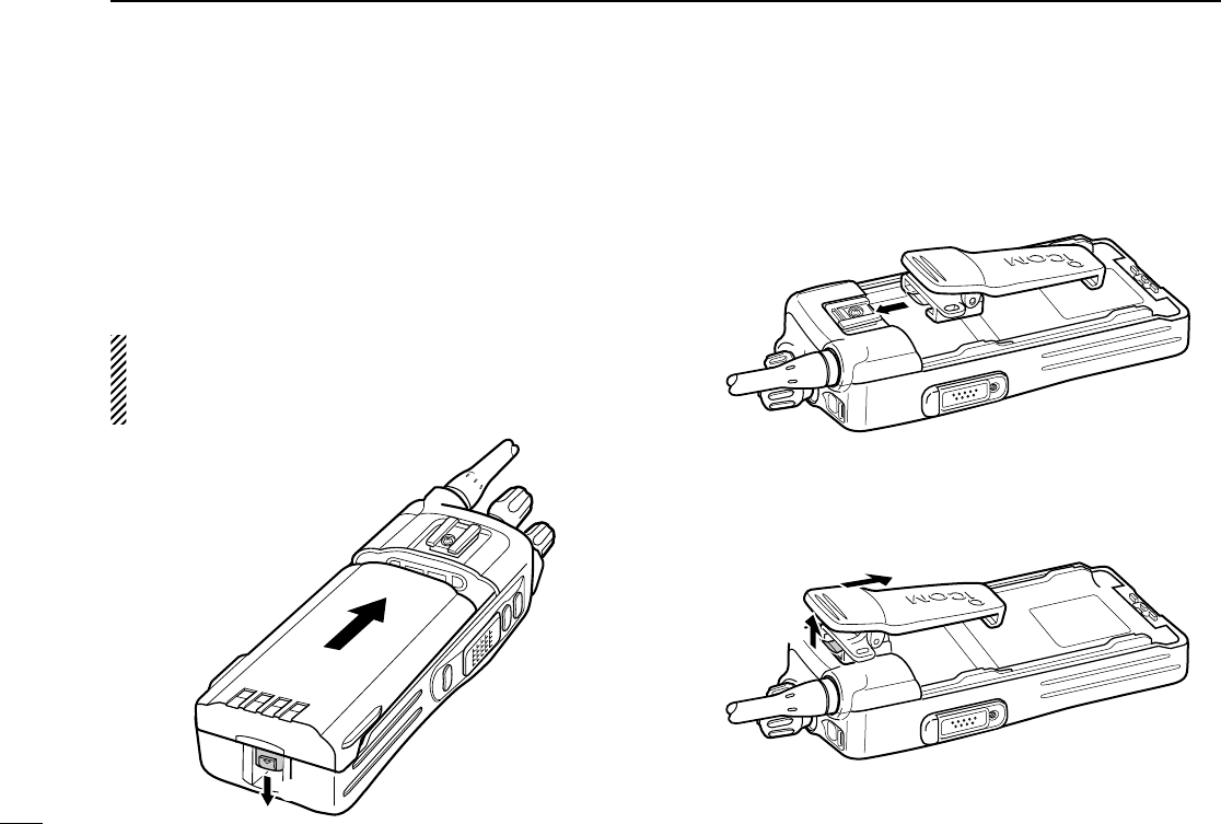
ïBattery pack
To attach the battery pack:
Slide the battery pack in the direction of the arrow (q), then
lock it with the battery release button.
• Slide the battery pack until the battery release button makes a ‘click’
sound.
To release the battery pack:
Push the battery release button in the direction of the arrow
(w) as shown below. The battery pack is then released.
NEVER release or attach the battery pack when the trans-
ceiver is wet or soiled. This may result water or dust get-
ting into the transceiver/battery pack and may result in the
transceiver being damaged.
DBelt clip
To attach the belt clip:
qRelease the battery pack if it is attached.
wSlide the belt clip in the direction of the arrow until the belt
clip is locked and makes a ‘click’ sound.
To detach the belt clip:
qRelease the battery pack if it is attached.
wPinch the clip (q), and slide the belt clip in the direction of
the arrow (w).
q
w
q
w
!IC-F70_F80.qxd 04.11.9 0:01 PM Page 2 (1,1)
3
1
ACCESSORIES
1
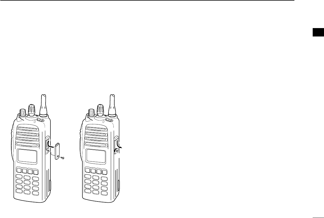
ïJack cover
Attach the jack cover when the optional speaker-microphone
is not used.
q
w
e
r
To attach the jack cover:
qInsert the jack cover into
the [SP MIC] connector.
wTighten the screw.
To detach the jack cover:
eUnscrew the screw with a
phillips screwdriver.
rDetach the jack cover for
the speaker-microphone
connection.
!IC-F70_F80.qxd 04.11.9 0:01 PM Page 3 (1,1)
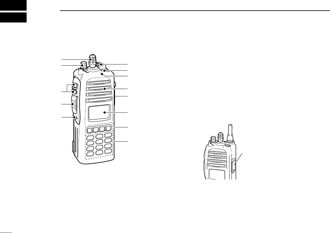
4
2PANEL DESCRIPTION
■Front panel
qVOLUME CONTROL [VOL]
Rotate to turn the power ON/OFF and adjusts the audio
level.
wROTARY SELECTOR
Rotate to select the pre-programmed memory channels or
the operating bank.
(Depending on the pre-setting)
eANTENNA CONNECTOR
Connects the supplied antenna.
rEMERGENCY SWITCH
Push and hold for a specified period to transmit an emer-
gency call.
*Desired function can be programmed by your dealer. (p. 7)
tBUSY/TRANSMIT INDICATOR
➥ Lights green while receiving a signal, or when the
squelch is open.
➥ Lights red while transmitting.
y[SP/MIC] JACK
Connect the optional speaker-microphone.
uFUNCTION DISPLAY (p. 6)
Displays a variety of information, such as an operating
channel number/name, 5-tone code, DTMF numbers and
audible condition, etc.
iDEALER-PROGRAMMABLE KEYS
Desired functions can be programmed independently by
your dealer. (p. 7)
[SP/MIC] jack cover
NOTE: Attach the [SP/MIC] jack
cover when the optional speaker-
microphone is not used.
(See p. 3 for details)
q
!2
!1
!0
w
e
r
t
Speaker
o
y
u
i
!IC-F70_F80.qxd 04.11.9 0:01 PM Page 4 (1,1)

5
2
PANEL DESCRIPTION
2
o10-KEYPAD (IC-F70DT/F70T or IC-F80DT/F80T only)
The keypad allows you to enter digits to:
• Select memory channels, tone channels and DTMF codes
(when in the DTMF code channel selection mode)
• Set TX codes and BIIS status number
• Input text message for SDM operation
• Start up with a password
• Input the Individual ID code for digital operation.
!0 MONITOR SWITCH
➥ Mute and release the CTCSS (DTCS) or 2-tone squelch
mute. Open any squelch/deactivate any mute while
pushing this key. (LMR operation only)
➥ Activates one of (or two of) the following functions on
each channel independently.
(PMR or BIIS PMR operation only)
• Push and hold the key to unmute the channel (audio is
emitted; ‘audible’condition).
• Push the key to toggle the mute and unmute conditions
(toggles ‘audible’and ‘inaudible’).
• Push the key to mute the channel (sets to ‘inaudible’only).
• Push the key to unmute the channel (sets to ‘audible’only).
• Push the key after communication is finished to send a ‘reset
code.’
• Push the key after communication is finished to send a ‘clear
down code’during BIIS operation on an MSK channel.
NOTE: The unmute condition (‘audible’conditions)
may automatically return to the mute condition
(‘inaudible’condition) after a specified period.
*Desired function can be programmed by your dealer. (p. 7)
!1 PTT SWITCH [PTT]
➥Push and hold to transmit; release to receive.
➥Push to transmit the call during MSK operation, depend-
ing on the setting.
!2 UP/DOWN SWITCHES
➥Push to select an operating channel.
➥Push to select a TX code channel after pushing
[TX CODE CH SELECT].
➥Push to select a DTMF channel after pushing [DTMF].
➥Push to select a scan group after pushing and holding
[SCAN].
➥Push to select a BIIS code, status number or SDM after
pushing [DIGITAL].
*Desired functions can be programmed independently by your
dealer. (p. 7)
!IC-F70_F80.qxd 04.11.9 0:01 PM Page 5 (1,1)
6
2PANEL DESCRIPTION
■Function display
qSIGNAL STRENGTH INDICATOR
Indicates relative signal strength level.
wLOW POWER INDICATOR
Appears when low output power is selected.
eAUDIBLE INDICATOR
➥Appears when the channel is in the ‘audible’(unmute)
condition.
➥Appears when the specified 2/5-tone/BIIS code is
received.
rCOMPANDER INDICATOR
Appears when the compander function is activated.
tSCRAMBLER INDICATOR
Appears when the voice scrambler function is activated.
yBELL INDICATOR
Appears/blinks when the specific 2/5-tone/BIIS code is
received, according to the pre-programming.
uCALL CODE MEMORY INDICATOR
Appears when the call code memory is selected.
iSCROLL INDICATOR
Appears when a received SDM including more than 12
characters is displayed.
oBATTERY INDICATOR
Appears or blinks when the battery power decreases to a
specified level.
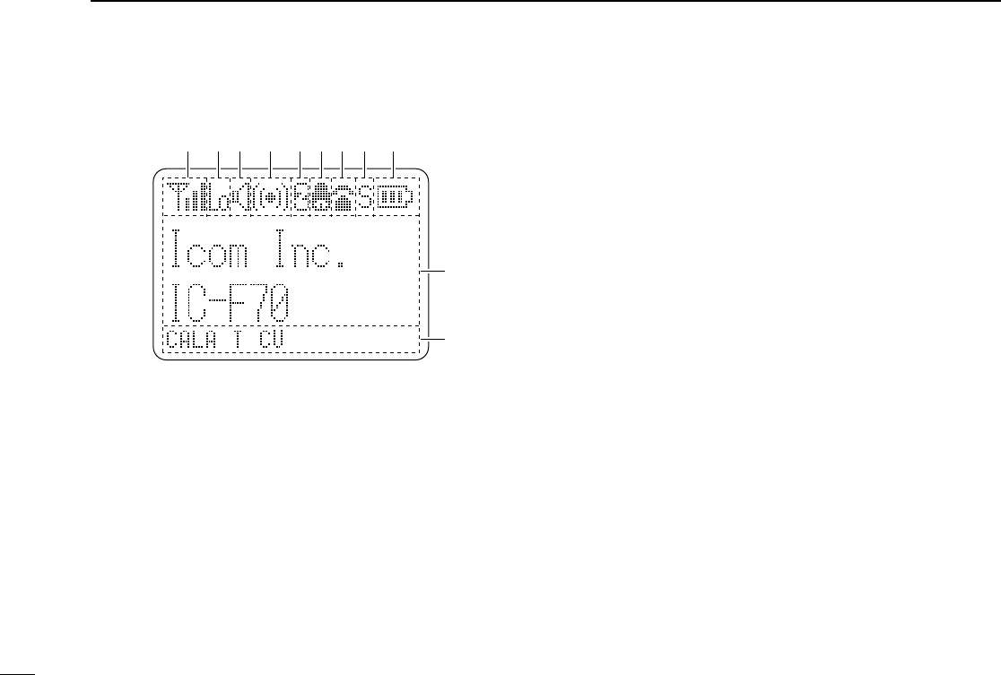
!0 ALPHANUMERIC DISPLAY
Displays an operating channel number, channel name, Set
mode contents, DTMF code, etc.
The indication mode can be selected from 1 line or 2 lines.
Ask your dealer for details.
In this instruction manual, the LCD illustration is described
using the 2 lines indication mode.
!1 KEY INDICATOR
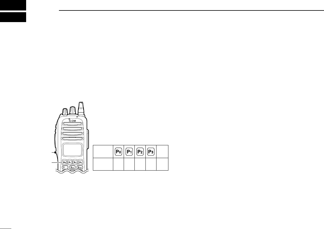
Indicate the programmed function of the front panel keys
([P0], [P1], [P2] and [P3]).
XTXC SET
q t oiuyrew
!0
!1
!IC-F70_F80.qxd 04.11.9 0:02 PM Page 6 (1,1)

7
2
PANEL DESCRIPTION
■Programmable function keys
The following functions can be assigned to [DIAL]*, [UP],
[DOWN], [P0], [P1], [P2] and [P3] programmable function
keys.
Consult your Icom dealer or system operator for details con-
cerning your transceivers programming.
If the programmable function names are bracketed in the fol-
lowing explanations, the specific key is used to activate the
function depends on the programming.
CH UP AND DOWN KEYS “UP” “DOWN”
➥Push to select an operating channel.
➥Push to select a transmit code channel after pushing [TX
Code CH Select].
➥Push to select a DTMF channel after pushing [DTMF
Autodial].
➥Push to select a scan group after pushing and holding
[Scan A Start/Stop]/[Scan B Start/Stop].
➥Push to select a BIIS code, status number or SDM after
pushing [Digital].
➥Push to select an Individual ID code or Talkgroup ID code
after pushing [Individual] or [Talkgroup].
ZONE SELECT KEY “ZONE”
Push this key, then select the desired zone using [CH Up]/
[CH Down].
What is “zone”?— The desired channels are assigned
into a zone according to the intended use. For example,
‘Staff A’and ‘Staff B’are assigned into a “Business” zone,
and ‘John’and ‘Cindy’are assigned into a “Private” zone.
SCAN A KEY “SCNA”
➥This key’s operation depends on the Power ON Scan setting.
When the power ON scan function is turned OFF;
Push to start and cancel scanning operation. In case of
transmission during scan, cancels scanning.
When the power ON scan function is turned ON;
Push to pause scanning. Scanning resumes after a speci-
fied time period has passed. In case of transmission during
scan, pauses scanning. Scanning resumes after a specified
time period has passed after the transmission is finished.
➥Push and hold this key for 1 sec. to indicate the scan group,
then select the desired group using [CH Up]/[CH Down].
SCAN B KEY “SCNB”
➥Push to start and cancel scanning operation. In case of
transmission during scan, pauses scanning. Scanning
resumes after a specified time period has passed after the
transmission is finished.
➥Push and hold this key for 1 sec. to indicate the scan
group, then select the desired group using [CH Up]/
[CH Down].
2
!IC-F70_F80.qxd 04.11.9 0:02 PM Page 7 (1,1)

8
2PANEL DESCRIPTION
SCAN TAG KEY “SCAD”
Push to add or delete the selected channel to/from the scan
group.
PRIORITY CHANNEL KEYS “PRA”/“PRAR”/“PRB”/“PRAR”
➥Push to select Priority A or Priority B channel.
➥Push and hold [Prio A (Rewrite)] to rewrite the Prio A chan-
nel.
MR-CH 1/2/3/4 KEYS “CH1”/“CH2”/“CH3”/“CH4”
Push to select an operating channel directly.
MONITOR KEY “MON”
➥Mute and release the CTCSS (DTCS) or 2-tone squelch
mute. Open any squelch/deactivate any mute while push-
ing this key. (LMR operation only)
➥Activates one of (or two of) the following functions on each
channel independently: (PMR or BIIS PMR operation only)
• Push and hold to un-mute the channel (audio is emitted; ‘Audible’
condition).
• Push to mute the channel (sets to ‘Inaudible’only).
• Push to un-mute the channel (sets to ‘Audible’only).
• Push after the communication is finished to send a ‘reset code’.
NOTE: The un-mute condition (‘Audible’condition) may
automatically return to the mute condition (‘Inaudible‘ con-
dition) after a specified period depending on programming.
LIGHT KEY “LAMP”
Push to turn the transceiver’s backlight ON temporarily when
the backlight function is turned OFF in user set mode.
LOCK KEY “LOCK”
Push and hold to electronically lock all programmable keys
except the following:
[Call] (incl. Call A and Call B), [Moni(Audi)] and [Emergency].
OUTPUT POWER SELECTION KEY “H/L”
Push to select the transmit output power temporarily or per-
manently, depending on the pre-setting.
•Ask your dealer for the output power level for each selection.
C.TONE CHANNEL ENTER KEY “TSEL”
Push to select the continuous tone channel using [CH Up]/
[CH Down] to change the tone frequency/code setting. The
selected channel remains set as the continuous tone chan-
nel until another channel is designated as such.
TALK AROUND KEY “TA”
Turn the talk around function ON and OFF.
•The talk around function equalizes the transmit frequency to the
receive frequency for transceiver-to-transceiver communication.
WIDE/NARROW KEY “W/N”
Push to toggle the IF bandwidth between wide and narrow.
• The wide passband width can be selected from 25.0 or 20.0 kHz
using the CS-F70/F1700
CLONING SOFTWARE
. (PMR or BIIS PMR
operation only) Ask your Dealer for details.
!IC-F70_F80.qxd 04.11.9 0:02 PM Page 8 (1,1)

9
2
PANEL DESCRIPTION
DTMF AUTODIAL KEY “DTMA”
➥Push to enter the DTMF channel selection mode. Then
select the desired DTMF channel using [CH Up]/[CH Down].
➥After selecting the desired DTMF channel, push this key to
transmit the DTMF code.
DTMF RE-DIAL KEY “DTMR”
Push to transmit the last-transmitted DTMF code.
CALL KEYS “CALL”/“CALA”/“CALB”
Push to transmit a 2/5-tone/BIIS ID code.
•Call transmission is necessary before calling another station
depending on your signalling system.
•[Call A] and/or [Call B] may be available when your system employs
selective ‘Individual/Group’calls. Ask your dealer which call is
assigned to each key.
EMERGENCY KEYS “EMGS”/“EMSS”/“EMGR”/“EMRS”
➥Push and hold for a specified period to transmit an emer-
gency call.
➥When [Emergency Single (Silent)] or [Emergency Repeat
(Silent)] is pushed, an emergency call is transmitted without
a beep emission and LCD indication change.
• If you want to cancel the emergency call, push (or push and
hold) the key again before transmitting the call.
• The emergency call is transmitted one time only or repeatedly
until receiving a control code depending on the pre-setting.
SURVEILLANCE KEY “SURV”
Push to turn the surveillance function ON or OFF.
When this function is turned ON, the beep is not emitted and
the LCD backlight does not light when a signal is received or
a key is pushed, etc.
TX CODE ENTER KEY “TXCE”
(PMR or BIIS PMR operation only)
Push to enter the ID code edit mode directly, for both 5-tone
and MSK. Then set the desired digit using [CH Up]/
[CH Down] or 10-keypad*. (p. 15)
*IC-F70DT/T or IC-F80DT/T only
TX CODE CHANNEL SELECT KEY “TXC”
➥Push to enter the ID code channel selection mode directly.
Then set the desired channel using [CH Up]/[CH Down].
(p. 14)
➥During ID code channel selection mode, push for 1 sec. to
enter the ID code edit mode for 5-tone and MSK. Then set
the desired digit using [CH Up]/[CH Down] or 10-keypad*.
(p. 15)
*IC-F70DT/T or IC-F80DT/T only
TX CODE CHANNEL UP/DOWN KEYS “TXCU”/“TXCD”
Push to select a TX code channel directly.
2
!IC-F70_F80.qxd 04.11.9 0:02 PM Page 9 (1,1)

10
2PANEL DESCRIPTION
ID MEMORY READ KEY “IDMS”
(PMR or BIIS PMR operation only)
➥Recalls detected ID codes.
•Push this key, then select the ID code using [CH Up]/[CH Down].
•Up to 5 ID’s are memorized.
➥Push and hold to erase the selected ID’s.
VOICE SCRAMBLER FUNCTION “SCR”
Push to toggle the voice scrambler function ON and OFF.
COMPANDER KEY “COMP”
Push to toggle the compander function ON and OFF.
The compander function reduces noise components from the
transmitted audio to provide clear communication.
USER SET MODE KEY “SET”
➥Push and hold to enter user set mode.
• During user set mode, push this key to select an item, and
change the value or condition using push [CH Up]/[CH Down].
➥Push and hold this key again to exit user set mode.
User set mode is also available via the ‘Power ON function.’
Refer to p. 17 also.
OPT OUT KEYS “OP1”/“OP2”/“OP3”
Push to control the output signal level from the optional unit
connector.
DIGITAL KEY “BIFN”(BIIS operation only)
➥Push to select the call ID list, transmit message and stand-
by condition. Toggles between queue channel and
received message record indication after queue channel is
selected.
➥Push and hold to select queue channel indication.
STATUS UP/DOWN KEYS “BIUP”/“BIDN”
(BIIS operation only)
➥While in the standby condition, push to display the trans-
mit status indication and select a status number.
➥When a received SDM is displayed, push to cancel the
automatic scroll and scroll the message manually.
➥When an SDM that contains more than 12 characters is
displayed, push to scroll the message manually.
TONE/NAC CH SELECT KEY “TSEL”
➥While in the analog mode operation, push to select the
continuous tone channel using [CH Up] or [CH Down] to
change the tone frequency/code setting.
➥While in the digital mode operation, push to select the NAC
channel using [CH Up] or [CH Down] to change the NAC
code setting.
➥While in the mixed (digital and analog) mode operation,
push to select the continuous tone channel using [CH Up]
or [CH Down] to change the tone frequency/code setting.
Then push this key to enter the setting. After that, the NAC
channel selection screen appears. Select the NAC chan-
nel using [CH Up] or [CH Down] to change the NAC code
setting. Then push this key to enter the setting.
!IC-F70_F80.qxd 04.11.9 0:02 PM Page 10 (1,1)

11
2
PANEL DESCRIPTION
2
DFor Digital mode operation only
INDIVIDUAL KEY “INDV”
➥Push to enter the individual ID code selection mode directly.
Then select the desired individual ID code using [CH Up]/
[CH Down]. (p. 16)
➥Push to stop the beep emission when receiving a matched
individual ID code.
TALKGROUP KEY “TGID”
➥Push to enter the talkgroup ID code selection mode directly.
Then select the desired talkgroup ID code using [CH Up]/
[CH Down]. (p. 16)
➥Push to stop the beep emission when receiving a matched
talkgroup ID code.
!IC-F70_F80.qxd 04.11.9 0:02 PM Page 11 (1,1)
12
3BASIC OPERATION
■Turning power ON
qRotate [VOL] to turn the power ON.
wIf the transceiver is programmed for a start up password,
input the digit codes as directed by your dealer.
• 10-keypad* can be used for password input.
*IC-F70DT/T or IC-F80DT/T only:
• The keys as below can be used for password input:
The transceiver detects numbers in the same block as identical.
Therefore “01234” and “56789” are the same.
eWhen the “PASSWORD” indication does not clear after
inputting 6 digits, the input code number may be incorrect.
Turn the power off and start over in this case.
■Channel selection
Several types of channel selections are available. Methods
may differ according to your system set up.
NON-ZONE TYPE:
Push [CH Up] or [CH Down], or rotate [ROTARY SELECTOR]*
to select the desired operating channel, in sequence; or, push
one of [MR-CH 1] to [MR-CH 4] keys to select a channel
directly.
• Up to 16 pre-programmed channels can be selected via [ROTARY
SELECTOR].
ZONE TYPE:
Push [Zone] then push [CH Up] or [CH Down] or rotate
[ROTARY SELECTOR]* to select the desired zone.
AUTOMATIC SCAN TYPE:
Channel setting is not necessary for this type. When turning
power ON, the transceiver automatically starts scanning.
Scanning stops when receiving a call.
*Depending on the pre-setting.
KEY
NUMBER 0
5
4
9
3
8
2
7
1
6
[MONI]
[P0]/[P1]/
[P2]/[P3]
MONI
!IC-F70_F80.qxd 04.11.9 0:02 PM Page 12 (1,1)
13
3
BASIC OPERATION
3
■Call procedure
When your system employs tone signaling (excluding CTCSS
and DTCS), the call procedure may be necessary prior to voice
transmission. The tone signalling employed may be a selec-
tive calling system which allows you to call specific station(s)
only and prevent unwanted stations from contacting you.
qSelect the desired TX code channel, 2/5-tone code,
Individual ID code* or Talkgroup ID code* according to
your System Operator’s instructions.
• This may not be necessary depending on programming.
• Refer to pgs. 14–16 for selection.
*Digital mode operation only.
wPush the call key (assigned to one of the dealer program-
mable keys; except for the Digital mode operation) or [PTT].
eAfter transmitting, the remainder of your communication
can be carried out in the normal fashion.
■Receiving and transmitting
Receiving:
qRotate [VOL] to turn the power ON.
wPush [CH Up] or [CH Down], or rotate [ROTARY SELEC-
TOR]* to select a channel in sequence.
*Depending on the pre-setting.
eWhen receiving a call, adjust the audio output level to a
comfortable listening level.
Transmitting:
Wait for the channel to become clear to avoid interference.
qPush [CALL] when initiating a call from your side.
• Coded audio may be heard from the transceiver, then “”
appears.
• This operation may not be necessary depending on your signal-
ing system. Ask your dealer for details.
wWhile pushing and holding [PTT], speak into the micro-
phone at your normal voice level.
eRelease [PTT] to return to receive.
IMPORTANT: To maximize the readability of your signal;
1. Pause briefly after pushing [PTT].
2. Hold the microphone 5 to 10 cm (2 to 4 inches) from
your mouth, then speak into the microphone at a normal
voice level.
Selective calling Non-selective calling
!IC-F70_F80.qxd 04.11.9 0:02 PM Page 13 (1,1)

14
3BASIC OPERATION
DTransmitting notes
• Transmit inhibit function
The transceiver has several inhibit functions which restrict
transmission under the following conditions:
- The channel is in mute condition (‘Inaudible’condition;
“”does not appear.)
- The channel is busy.
- Un-matched (or matched) CTCSS is received.
(Depending on the pre-setting.)
- Un-matched (or matched) NAC is received.*
(Depending on the pre-setting.)
- Un-matched (or matched) Individual ID or Talkgroup ID is
received.*
- The selected channel is a ‘receive only’channel.
*Digital mode operation only.
• Time-out timer
After continuous transmission for the pre-programmed time
period, the time-out timer is activated, causing the transceiv-
er to stop transmitting.
• Penalty timer
Once the time-out timer is activated, transmission is further
inhibited for a period determined by the penalty timer.
DTX code channel selection
If the transceiver has [TX Code CH Select] assigned to it, the
indication can be toggled between the operating channel
number (or name) and TX code channel number (or name).
When the TX code channel number (or name) is displayed,
[CH Up]or [CH Down] selects the TX code channel.
USING [TX CODE CH SELECT] KEY:
qPush [TX Code CH Select]—a TX code channel number
(or name) appears.
wPush [CH Up] or [CH Down] to select the desired TX code
channel.
ePush [Call] (or [PTT] during MSK operation) to transmit the
selected TX code.
USING [TX CODE CH UP]/[TX CODE CH DOWN] KEY:
If the transceiver has a [TX Code CH Up] or [TX Code CH
Down] key assignment, the programmed TX code channel
can be selected directly when pushed.
NOTE for PMR or BIIS PMR operation:
• The LCD indication does not change when the operating
channel number (or name) is displayed.
• To check the selected TX code, push [TX Code CH
Select].
!IC-F70_F80.qxd 04.11.9 0:02 PM Page 14 (1,1)

15
3
BASIC OPERATION
DTX code number edit
(PMR or BIIS PMR operation only)
If the transceiver has [TX Code CH Select] or [TX Code
Enter] assigned to it, TX code contents can be edited within
the allowable digits.
USING [TX CODE CH SELECT] KEY:
qPush [TX Code CH Select] to enter the TX code channel
selection mode.
• Select the desired channel before entering the TX code channel
selection mode if necessary.
wPush [TX Code CH Select] for 1 sec. to enter the TX code
edit mode.
ePush [TX Code CH Select] to select the desired digit to be
edited.
• The digit to be edited blinks.
rPush [CH Up], [CH Down] or 10-keypad* to set the desired
digit.
tPush [TX Code CH Select] to set the digit. The digit to the
right will blink automatically.
• When the 10-keypad* is used for setting, the digit to the right will
blink automatically without pushing [TX Code CH Select].
yRepeat rand tto input all allowable digits.
uPush [Call] or [PTT] to transmit the edited TX code.
*IC-F70DT/T or IC-F80DT/T only
USING [TX CODE ENTER] KEY:
qSelect the desired TX code channel via [TX Code CH
Select]+[CH Up] or [CH Down], [TX Code CH Up] or [TX
Code CH Down].
wPush [TX Code Enter] to enter the TX code edit mode.
ePush [TX Code Enter] to select the desired digit to be edit-
ed.
• The digit to be edited blinks.
rPush [CH Up], [CH Down] or 10-keypad* to set the desired
digit .
tPush [TX Code Enter] to set the digit. The digit to the right
will blink automatically.
• When the 10-keypad* is used for setting, the digit to the right will
blink automatically without pushing [TX Code CH Enter].
yRepeat rand tto input all allowable digits.
uPush [Call] or [PTT] to transmit the edited TX code.
*IC-F70DT/T or IC-F80DT/T only
3
!IC-F70_F80.qxd 04.11.9 0:02 PM Page 15 (1,1)

16
3BASIC OPERATION
DIndividual ID code selection
(Digital mode operation only)
If the transceiver has [Individual] assigned to it, the indication
can be toggled between the operating channel number (or
name) and Individual ID code (or name). When the Individual
ID code (or name) is displayed, [CH Up] or [CH Down] selects
the desired Individual ID code.
qPush [Individual]—an Individual ID code (or name)
appears.
wPush [CH Up] or [CH Down] to select the desired
Individual ID code.
ePush [PTT] to transmit the selected Individual ID code.
rPush [Individual]—cancels the selected Individual ID code
(return to the pre-set Talkgroup ID code in the channel.)
DTalkgroup ID code selection
(Digital mode operation only)
If the transceiver has [Talkgroup] assigned to it, the indication
can be toggled between the operating channel number (or
name) and Talkgroup ID code (or name). When the Talkgroup
ID code (or name) is displayed, [CH Up] or [CH Down] selects
the desired Talkgroup ID code.
qPush [Talkgroup]—a Talkgroup ID code (or name)
appears.
wPush [CH Up] or [CH Down] to select the desired
Talkgroup ID code.
ePush [PTT] to transmit the selected Talkgroup ID code.
rChange the channel—cancels the selected Talkgroup ID
code (return to the pre-set Talkgroup ID code in the chan-
nel.)
DDTMF transmission
If the transceiver has [DTMF Autodial] assigned to it, the
automatic DTMF transmission function is available. Up to 8
DTMF channels are available.
TO SELECT A TX CODE:
qPush [DTMF Autodial]—a DTMF channel appears.
wPush [CH Up] or [CH Down] to select the desired DTMF
channel.
ePush [DTMF Autodial] to transmit the DTMF code in the
selected DTMF channel.
!IC-F70_F80.qxd 04.11.9 0:02 PM Page 16 (1,1)
17
3
BASIC OPERATION
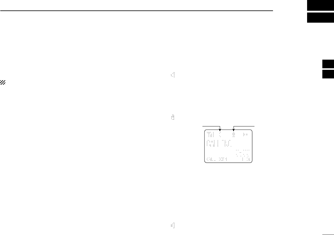
■User set mode
User set mode is accessed at power ON and allows you to
set seldom-changed settings. In this case you can “cus-
tomize” the transceiver operation to suit your preferences and
operating style.
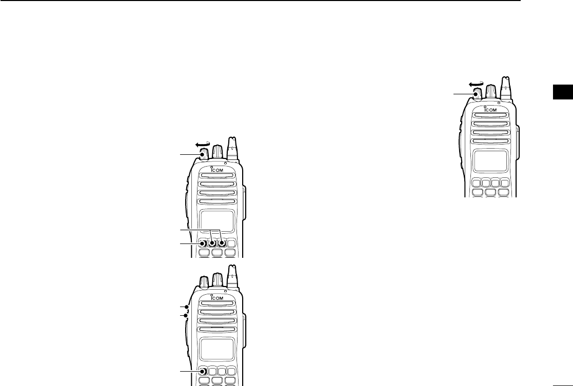
Entering the user set mode:
qWhile pushing and holding [P1]
and [P2], rotate [VOL] to turn
the power ON. Then, push and
hold [P0] to enter user set
mode.
wPush [P0] several times to
select the appropriate item.
Then, push [Up] or [Down] to
set the desired level/condition.
• Available set mode functions are
Backlight, LCD Contrast, Beep,
Beep Level, SQL Level, AF Min
Level, Mic Gain, Vox Gain, Vox
Delay and Battery Voltage.
eRotate [VOL] to turn the power
OFF to exit set mode.
User set mode is also available via
a programmable key. Please refer
to p. 10 [User Set Mode] section.
[P0]
[P1]/[P2]
[VOL]
[P0]
[Down]
[Up]
[VOL]
3
!IC-F70_F80.qxd 04.11.9 0:02 PM Page 17 (1,1)

18
3BASIC OPERATION
■Scrambler function
The voice scrambler function provides private communication
between stations. The frequency inversion type is equipped
to all versions, moreover, the optional Rolling or Non-rolling
type can be available.
qPush [Scrambler] to turn the scrambler function ON.
• “” appears.
wPush [Scrambler] again to turn the scrambler function
OFF.
• “” disappears.
!IC-F70_F80.qxd 04.11.9 0:02 PM Page 18 (1,1)
19
4
BIIS OPERATION
3
4
■Default setting
The following functions are assigned to each programmable
key as the default. However, the assigned function can be
changed by your dealer. Ask your dealer for details.
During digital mode operation, BIIS is not available.
NOTE: [TX Code Enter] must be assigned to a key.
[P0]; Call : Push to transmit a 5-tone/BIIS call
when the selected channel is a 5-tone
or MSK channel.
• “CALL” is displayed on the key indicator.
[P1]; Digital : Push to select the call list ID/transmit
message, or to display the receive
message record for selection.
• “BIFN” is displayed on the key indicator.
[P3]; TX Code Enter : Push to enter the ID code edit mode
directly for both 5-tone and MSK.
• “TXCE” is displayed on the key indicator.
[P2]; Null : No function is assigned.
[MONI]; Moni(Audi) : Push this key after the communica-
tion to send a ‘Clear down’signal dur-
ing MSK channel operation.
[Up]/[Down]; CH Up/Down
: While in the standby condition,
selects the operating channel.
After pushing [Digital] or [TX Code
CH Select], selects call list or TX code
channel, respectively.
■Receiving a call
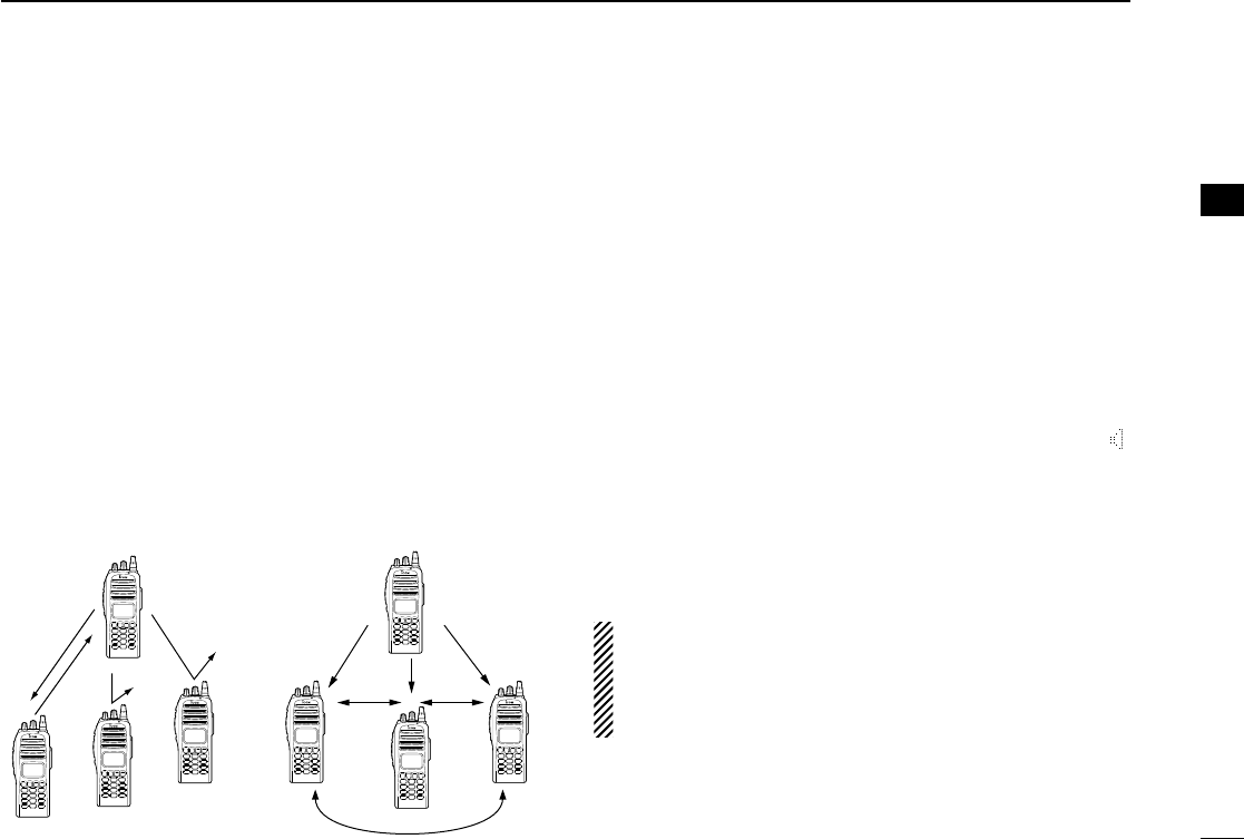
DDIndividual call
qWhen an individual call is received;
•Beeps sound.
•“ ” appears and the mute is released.
•The programmed text message (e.g.“CALLING”) and the calling
station ID (or text) is displayed when the indication mode is 2
lines.
•The programmed text message (e.g.“CALLING”) and the calling
station ID (or text) is displayed alternately when the indication
mode is 1 line, depending on the setting.
•“ ” appears or blinks depending on the setting.
wPush and hold [PTT], then speak into the microphone at a
normal voice level.
•TX indicator lights red.
eRelease [PTT] to return to receive.
•BUSY indicator lights green while receiving a signal.
rTo finish the conversation, push [P4] (Moni(Audi)) to send
the ‘Clear down’signal.
•Either station can send a ‘Clear down’signal.
•“CLR DOWN” is displayed for 2 sec. (approx.).
•“ ” disappears and the transceiver returns to the standby condi-
tion.
X
Appears Appears or
blinks
!IC-F70_F80.qxd 04.11.9 0:02 PM Page 19 (1,1)
20
4BIIS OPERATION
DDGroup call
qWhen a group call is received;
•Beeps sound.
•“ ” appears and the mute is released.
•The programmed text message (e.g.“GROUP”) and the calling sta-
tion ID (or text) is displayed when the indication mode is 2 lines.
•The programmed text message (e.g.“GROUP”) and the calling
station ID (or text) is displayed alternately when the indication
mode is 1 line, depending on the setting.
•“ ” appears or blinks depending on the setting.
wPush and hold [PTT], then speak into the microphone at a
normal voice level.
•TX indicator lights red.
NOTE: Only one station is permitted to speak.
eRelease [PTT] to return to receive.
•BUSY indicator lights green while receiving a signal.
rTo finish the conversation, push [MONITOR] (Moni(Audi))
to send the ‘Clear down’signal.
•Either station can send a ‘Clear down’signal.
•“CLR DOWN” is displayed for 2 sec. (approx.)
•“ ” disappears and the transceiver returns to the standby con-
dition.
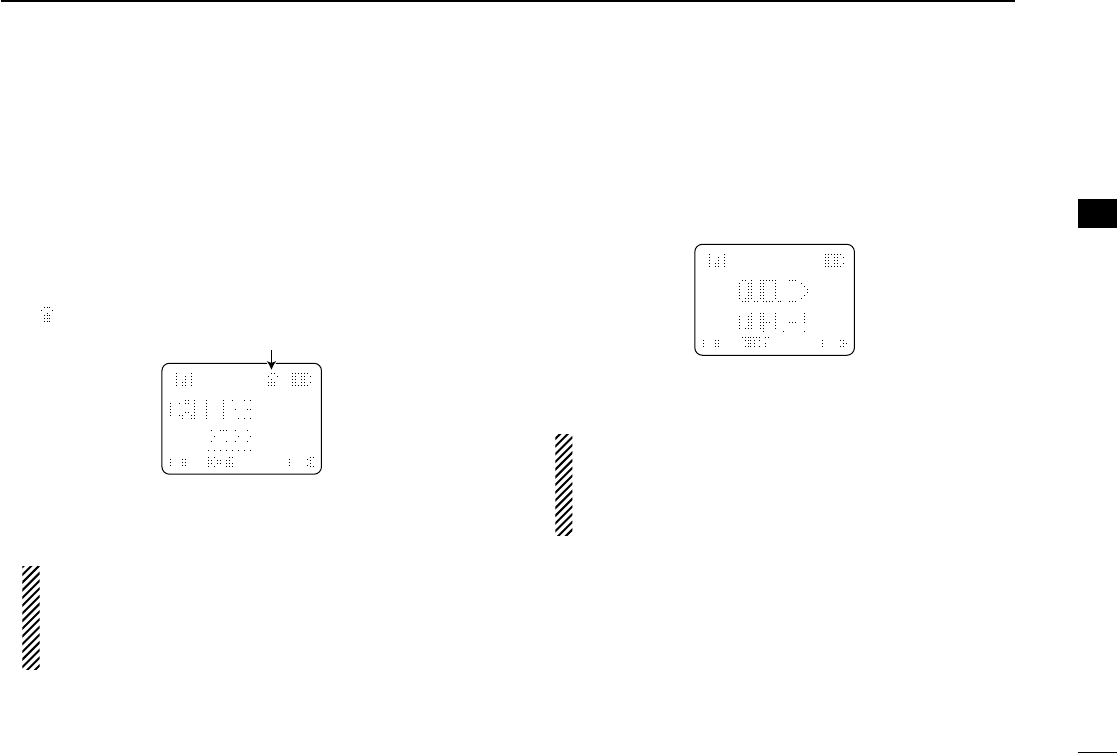
DDDisplaying the received call record
— Queue indication
The transceiver memorizes the calling station ID in the mem-
ory. Up to 3 calls can be memorized, and the oldest call
record is erased when a 4th call is received. However, once
the transceiver is powered OFF, the all records are cleared.
qPush [P1] (Digital) for 1 sec.
•Displays following indication.
When a record is available
When no record is available
wPush [Up] or [Down] to select the desired call.
ePush [P1] (Digital) for 1 sec. again to return to the standby
condition.
•When no operation is performed for 30 sec., the transceiver
returns to the standby condition automatically.
X
X
X
Appears Appears or blinks
!IC-F70_F80.qxd 04.11.9 0:02 PM Page 20 (1,1)
21
4
BIIS OPERATION
4
■Transmitting a call
A total of 3 ways for code selection are available—selecting
the call code from memory, entering the call code from the
keypad and calling back from the queue channel record.
DDUsing call memory
qWhile in the standby condition, push [P1] (Digital) to enter
the call code memory channel selection mode.
•“ ” appears.
wPush [Up] or [Down] to select the desired call code.
ePush [P0] (Call) or [PTT]* to call.
*PTT call can be made only when PTT call capability is permitted.
NOTE: When no answer back is received, the trans-
ceiver repeats the call 3 times (default) automatically,
and “WAIT”is displayed during each call. However, an
error beep sounds and “FAILED”is displayed when no
answer back is received after the calls.
rPush [PTT] to transmit; release to receive.
tPush [P4] (Moni(Audi)) to send the ‘Clear down’signal.
DDCalling back from the queue channel
qWhile in the standby condition, push [P1] (Digital) for
1 sec. to enter the queue memory channel selection mode.
wPush [Up] or [Down] to select the desired record.
ePush [P0] (Call) or [PTT]* to call.
*PTT call can be made only when PTT call capability is permitted.
NOTE: When no answer back is received, the trans-
ceiver repeats the call 3 times (default) automatically,
and “WAIT”is displayed during each call. However, an
error beep sounds and “FAILED”is displayed when no
answer back is received after the calls.
rPush [PTT] to transmit; release to receive.
tPush [P4] (Moni(Audi)) to send the ‘Clear down’signal.
X
X
Appears
!IC-F70_F80.qxd 04.11.9 0:02 PM Page 21 (1,1)

22
4BIIS OPERATION
DDDirect code entry
qWhile in the standby condition, push [P3] (TX Code Enter)
to enter the TX code edit mode.
•Code digit for editing blinks.
wPush [P3] (TX Code Enter) to select the desired digit to be
edited.
•Digit for editing differs according to the setting.
eSet the desired digit using [CH Up]/[CH Down] or 10-key-
pad*.
*IC-F70DT/T or IC-F80DT/T only
rPush [P3] (TX Code Enter) to set the digit, then the digit
to the right will blink automatically.
• When the 10-keypad is used for setting, the digit to the right will
blink automatically without pushing [P3] (TX Code Enter).
tRepeat eand rto input all allowable digits.
yPush [P0] (Call) or [PTT]* to call.
*PTT call can be made only when PTT call capability is permitted.
NOTE: When no answer back is received, the trans-
ceiver repeats the call 3 times (default) automatically,
and “WAIT”is displayed during each call. However, an
error beep sounds and “FAILED”is displayed when no
answer back is received after the calls.
uPush [PTT] to transmit; release to receive.
iPush [P4] (Moni(Audi)) to send the ‘Clear down’signal.
For your information
When the “UpDate” setting for the call code is enabled, the
set code is overwritten into the call code memory.
X
!IC-F70_F80.qxd 04.11.9 0:02 PM Page 22 (1,1)
23
4
BIIS OPERATION
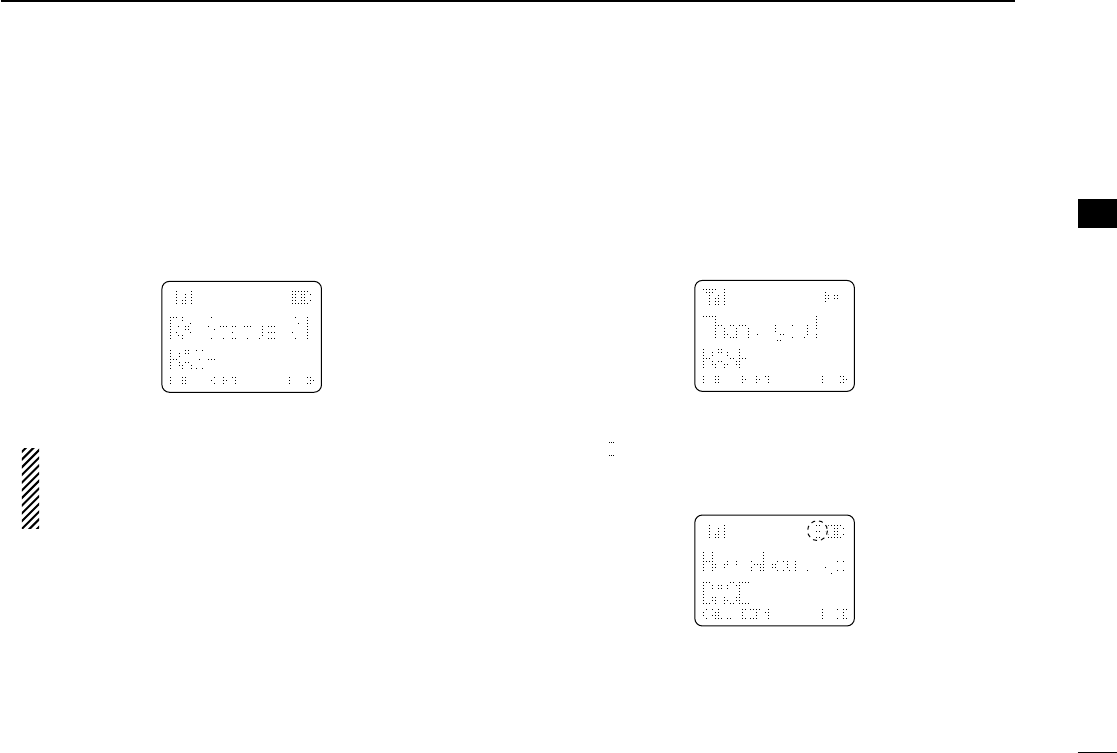
■Receiving a message
DDReceiving a status message
qWhen a status message is received;
• Beeps sound.
• The calling station ID (or text) and the status message is dis-
played alternately when the indication mode is 1 line, depending
on the setting.
wPush [P4] (Moni(Audi)) to return to the standby condition.
NOTE: Only the calling station ID (or text) is displayed (no
message is displayed alternately) when the scroll timer is
set to ‘OFF.’In this case, push [Status Up]/[Status Down]
to display the status message manually.
DDReceiving an SDM (Short Data Message)
qWhen an SDM is received;
• Beeps sound.
• The calling station ID (or text) and the SDM is displayed alter-
nately when the indication mode is 1 line, depending on the set-
ting.
wWhen the received SDM includes more than 12 charac-
ters, “” appears and the message scrolls automatically,
when the automatic scroll function is activated.
• Push [Status Up]/[Status Down] to scroll the message manually.
ePush [P4] (Moni(Audi)) to return to the standby condition.
X
X
X
4
!IC-F70_F80.qxd 04.11.9 0:02 PM Page 23 (1,1)

24
4BIIS OPERATION
DDReceived message selection
The transceiver memorizes the received message in the
memory. Up to 6 messages for status and SDM, or 95 char-
acter SDM’s can be memorized. The oldest message is
erased when the 7th message is received. However, once the
transceiver is powered OFF, all messages are cleared.
qPush [P1] (Digital) for 1 sec.
•Displays queue memory.
wPush [P1] (Digital) momentarily.
•Displays message memory.
When a message is available
When no message is available
ePush [Up] or [Down] to select the desired message.
•When selecting the SDM that includes more than 12 characters,
“” appears and the message scrolls automatically when the
automatic scroll function is activated.
• Push [Status Up]/[Status Down] to scroll the message manually.
rPush [P1] (Digital) for 1 sec. again to return to the standby
condition.
•When no operation is performed for 30 sec., the transceiver
returns to the standby condition automatically.
X
X
!IC-F70_F80.qxd 04.11.9 0:02 PM Page 24 (1,1)

25
4
BIIS OPERATION
■Transmitting a status
DDGeneral
The status message can be selected with the programmed
text, and the message text is also displayed on the function
display of the called station.
Up to 24 status types (1 to 24) are available, and the status
messages 22 and 24 have designated meanings.
Status 22: Emergency*
Status 24: GPS request
*The status 22 can also be used as a normal status message by
disabling the designated meaning. However, the status 24 is fixed.
The status call can be sent with both individual and group
calls.
DDTransmitting a status
qWhile in the standby condition, push [P1] (Digital), then
push [Up] or [Down] to select the desired station/group
code.
wPush [P1] (Digital) again, then push [UP] or [DOWN] to
select the desired status message.
Or, you can select the desired status message using
[Status Up]/[Status Down] key directly.
ePush [P0] (Call) or [PTT]* to transmit the status message
to the selected station/group.
*PTT call can be made only when PTT call capability is permitted.
•2 beeps will sound and the transceiver returns to the standby
condition automatically when the transmission is successful.
X
Status message is displayed.
4
!IC-F70_F80.qxd 04.11.9 0:02 PM Page 25 (1,1)

26
4BIIS OPERATION
DDGeneral
The short data message, SDM, can be sent to an individual
station or group stations. Also, 8 SDM memory channels are
available and the messages can be edited via PC program-
ming.
DDTransmitting an SDM
qWhile in the standby condition, push [P1] (Digital), then
push [Up] or [Down] or rotate [DIAL] to select the desired
station/group code.
wPush [P1] (Digital) again, then push [Up] or [Down] to
select the desired SDM.
Or, you can select the desired SDM using [Status Up]/
[Status Down] key directly.
ePush [P0] (Call) or [PTT]* to transmit the SDM to the
selected station/group.
*PTT call can be made only when PTT call capability is permitted.
•2 beeps will sound and the transceiver returns to the standby
condition automatically when the transmission is successful.
DDProgramming an SDM memory
(IC-F70DT/T or IC-F80DT/D only)
qDuring standby condition, push [P1] (Digital) twice, then
push [Up] or [Down] to select the desired SDM to be edit-
ed.
wPush [M] or [#] to enter the message editing condition.
•The first character blinks when [#] is pushed, the last character
blinks when [M] is pushed.
ePush the appropriate digit key, [0] to [9], to enter the
desired character.
•See the table at right for the available characters.
•Pushing [UP] also enters space, pushing [DOWN] deletes the
selected character.
rPush [#] to move the cursor to the right, push [M] to move
the cursor to the left.
tRepeat steps eand rto set the desired text message.
yPush [P1] (Digital) for 1 sec. to overwrite the set content
into the memory.
•Push [P1] (Digital) momentarily to cancel the editing and return to
the original message indication.
X
Blinks
When [#] is pushed.
X
SDM is displayed.
■Transmitting an SDM (Short Data Message)
!IC-F70_F80.qxd 04.11.9 0:02 PM Page 26 (1,1)

27
4
BIIS OPERATION
•Available characters
NOTE: A decimal point can only be written with the CS-
F70/F1700
CLONING SOFTWARE
. Pre-programmed charac-
ters can be rewritten with the 10-keypad, except for the
decimal point, as it is not included in the transceiver char-
acter list, and cannot be displayed again.
■Position data transmission
When the optional cable (OPC-966) and a GPS receiver is
connected to the transceiver, the position (longitude and lati-
tude) data can be transmitted automatically.
Ask your dealer or system operator for connection details.
The position data is transmitted when;
•Status 24 message is received
*When the status 24 message, GPS request, is received.
•Fully automatic
When automatic position transmission is enabled, send
the position data according to ‘Time Marker’and ‘Interval
Timer’settings.
•PTT is released
When ‘Send with Logoff’is enabled.
-Set the ‘Log-In/Off’item as ‘L-OFF.’
•After sending a status message
When ‘Send with Status’is enabled.
•After sending an SDM
When ‘Send with SDM’is enabled.
•After sending status 22 (Emergency)
When ‘Send with Emergency’is enabled.
Key Characters
[0]
[1]
[2]
[3]
[4]
[5]
[6]
[7]
[8]
[9]
4
!IC-F70_F80.qxd 04.11.9 0:02 PM Page 27 (1,1)

28
4BIIS OPERATION
■Printer connection
When the optional cable is connected to the transceiver, a
printer can be connected to print out the received SDM con-
tent and the ID of the station who sent the message.
Ask your dealer or system operator for connection details.
■Digital ANI
The own ID can be transmitted each time the PTT is pushed
(log-in) or released (log-off) during individual or group call
communications.
By receiving the ANI, the communication log can be recorded
when using a PC dispatch application.
In addition, when using the ANI with log-in, the PTT side tone
function can be used to inform you that the ID is sent and
voice communication can be performed.
■Auto emergency transmission
When [Emergency Single (Silent)] or [Emergency Repeat
(Silent)] is pushed, an emergency signal is automatically
transmitted for the specified time period.
The status 22 (Emergency) is sent to the selected ID station,
and the position data is transmitted after the emergency sig-
nal when a GPS receiver is connected to the transceiver.
The emergency transmission is performed on the emergency
channel, however, when no emergency channel is specified,
the signal is transmitted on the previously selected channel.
There is no change in the function display or beep emission
during automatic emergency transmission.
■Stun function
When the specified ID, set as a killer ID, is received, the stun
function is activated.
When the killer ID is received, the transceiver switches to the
password required condition. Entering of the password via the
keypad is necessary to operate the transceiver again in this
case.
!IC-F70_F80.qxd 04.11.9 0:02 PM Page 28 (1,1)

29
4
BIIS OPERATION
■BIIS indication
The following indications are available for the BIIS operation
on an MSK channel.
CONNECT : Individual/group call is successful.
OK : Message (status or SDM) transmission is suc-
cessful.
FAILED : No answer back is received.
WAIT : Appears during retry of the call (2nd call).
CLR DOWN : End the communication.
BUSY : Operating channel is in the busy condition.
■Priority A channel selection
When one of the following operations is performed, the trans-
ceiver selects the Priority A channel automatically.
Priority A is selected when;
•Clear down signal is received/transmitted
- Set the ‘Move to PrioA CH’item as ‘Clear down.’
•Turning the power ON
The Priority A channel is selected each time the transceiv-
er power is turned ON.
•Status call
The Priority A channel is selected when transmitting a sta-
tus call.
- Enable the ‘Send Status on PrioA CH’item in the MSK
configuration.
4
!IC-F70_F80.qxd 04.11.9 0:02 PM Page 29 (1,1)
30
5OPTIONAL UNIT INSTALLATION
■Optional unit installation
Install the optional unit as follows:
qRotate [VOL] to turn the power OFF, and remove the bat-
tery pack. (p. 2)
wUnscrew a screw, then remove the rear panel.
eUnscrew the 6 screws, then take off the chassis from the
front panel in the direction of the arrow.
BE CAREFUL! Flat cable is connected between the MAIN unit on
the chassis and front panel.
rInstall the optional unit as shown below.
tReplace the chassis and the rear panel, and attach the
battery pack. Then rotate [VOL] to turn the power ON.
NOTE: The optional UT-111
LTR TRUNKING BOARD
requires
some PC board modifications. Please refer to the addi-
tional installation as shown on the next page.
UT-109
!IC-F70_F80.qxd 04.11.9 0:02 PM Page 30 (1,1)
31
5
OPTIONAL UNIT INSTALLATION
5
■UT-111 installation
The following PC board modification is required when
installing the optional UT-111
LTR TRUNKING BOARD
:
qRotate [VOL] to turn the power OFF, and remove the bat-
tery pack. (p. 2)
wRemove the rear panel and take off the chassis as shown
on p. 30 (Optional unit installation).
eCut the pattern on the PCB at the CP18, then solder CP19
on the chassis as shown below.
rInstall the UT-111
LTR TRUNKING BOARD
as described in the
Optional unit installation (p. 30).
tReplace the chassis and the rear panel, and attach the
battery pack. Then rotate [VOL] to turn the power ON.
NOTE: When uninstalling the unit
Be sure to re-solder the disconnected points and un-sol-
der the connected points as above when you remove the
unit. Otherwise no TX modulation or AF output is available.
Un-solderRe-solder
Remove
CP-19
CP-18
!IC-F70_F80.qxd 04.11.9 0:02 PM Page 31 (1,1)

32
6BATTERY CHARGING
■Battery charging
Prior to using the transceiver for the first time, the battery
pack must be fully charged for optimum life and operation.
CAUTION: To avoid damage to the transceiver, turn the
power OFF while charging.
• Recommended temperature range for charging:
+10°C to +40°C (+50°F to +104°F)
• Use the specified chargers (BC-119N and BC-121N).
NEVER use another manufacture’s charger.
• Use the specified AC adapter. NEVER use another manu-
facture’s adapter.
■Battery caution
RDANGER Charge the specified Icom batteries only.
Only tested and approved for use with genuine Icom batter-
ies. Fire and/or explosion may occur when a third party bat-
tery pack or counterfeit product is charged.
CAUTION! NEVER insert battery pack/transceiver (with the
battery pack attached) in a wet or soiled condition into the
charger. This may result in corrosion of the charger terminals
or damage to the charger. The charger is not waterproof and
water can easily get into it.
NEVER incinerate used battery packs. Internal battery gas
may cause an explosion.
NEVER immerse the battery pack in water. If the battery
pack becomes wet, be sure to wipe it dry BEFORE attaching
it to the transceiver.
NEVER short the terminals of the battery pack. Also, current
may flow into nearby metal objects, such as a necklace, etc.
Therefore, be careful when carrying with, or placing near
metal objects, carrying in handbags, etc.
AVOID leaving the battery pack in a fully charged, or completely
discharged condition for long time. It causes shorter battery life.
In case of leaving the battery pack unused for a long time, it
must be kept safely after discharge, or use the battery until the
battery indicator appears, then remove it from the transceiver.
If your battery pack seems to have no capacity even after
being charged, fully charge the battery pack again. If the bat-
teries still do not retain a charge (or very little), new battery
pack must be purchased.
Recommendation:
Charge the supplied battery pack for a maximum of
up to 10 hours. Li-Ion batteries are different from Ni-
Cd batteries in that it is not necessary to completely
charge and discharge them to prolong the battery life.
Therefore, charging the battery in intervals, and not
for extended periods is recommended.
!IC-F70_F80.qxd 04.11.9 0:02 PM Page 32 (1,1)
33
6
BATTERY CHARGING
6
■Optional battery chargers
ïAD-110 installation
qInstall the AD-110 desktop charger adapter into the holder
space of the BC-119N/BC-121N.
wConnect the plugs of the BC-119N/BC-121N to the AD-110
desktop charger adapter with the connector, then install
the adapter into the charger with the supplied screws.
ïRapid charging with the BC-119N+AD-110
The optional BC-119N provides rapid charging of battery
packs. The following items are additionally required.
• AD-110 charger adapter
• An AC adapter (may be supplied with BC-119N depending
on version) or the DC power cable (OPC-515L/CP-17L).
AD-110 charger
adapter is installed
in BC-119N.
AC adapter
(Not supplied with
some versions.)
Optional OPC-515L (for 13.8 V
power source) or CP-17L (for 12
V cigarette lighter socket) can be
used instead of the AC adapter.
BP-235
TRANSCEIVER
AD-110
Connectors
q
Screws supplied
with the charger
adapter
Plugs
w
!IC-F70_F80.qxd 04.11.9 0:02 PM Page 33 (1,1)
34
6BATTERY CHARGING
ïRapid charging with the BC-121N+AD-100
The optional BC-121N allows up to 6 battery packs to be
charged simultaneously. The following items are additionally
required.
• Six AD-100 charger adapters
• An AC adapter (BC-124) or the DC power cable (OPC-656)
IMPORTANT!: Battery charging
Ensure the guide lobs on the battery pack are correctly
aligned with the guide rails inside the charger adapter.
(This illustration is described with the BC-119N.)
Lobs
Guide rails
MULTI-CHARGER
AD-110 charger
adapters are installed
in each slot.
DC power cable (OPC-656)
(Connect with the DC power supply;
13.8 V/at least 7 A
)
AC adapter
(Purchased
separately)
TRANSCEIVER
BP-235
!IC-F70_F80.qxd 04.11.9 0:02 PM Page 34 (1,1)
35
7
OPTIONAL BATTERY CASE
6
7
■Optional battery case
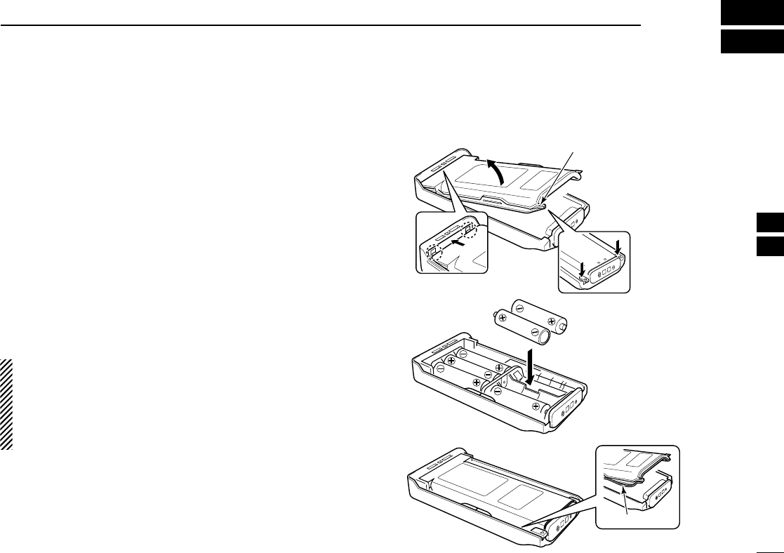
When using the optional battery case attached to the trans-
ceiver, install 6 ×AA (LR6) size alkaline batteries as illustrated
at right. The BP-237 meets JIS waterproof specification grade
4.
qHook your finger under the latch, and open the cover in the
direction of the arrow (q). (Fig.1)
wThen, install 6 ×AA (LR6) size alkaline batteries. (Fig.2)
• Install the alkaline batteries only.
• Be sure to observe the correct polarity.
• Do not pin the ribbon under the batteries.
eClose the cover by fitting in the direction of the arrow (w)
first, then check the latch is in place (e). (Fig.1)
• Be sure the gasket and the ribbon are set correctly, and do not
protrude from the battery case. (Fig.3)
CAUTION:
•When installing batteries, make sure they are all the same
brand, type and capacity. Also, do not mix new and old
batteries together.
•Keep battery contacts clean. It’s a good idea to clean bat-
tery terminals once a week.
q
BP-237
Fig.1
Fig.2
Fig.3
e
Gasket
Latch
w
!IC-F70_F80.qxd 04.11.9 0:02 PM Page 35 (1,1)
36
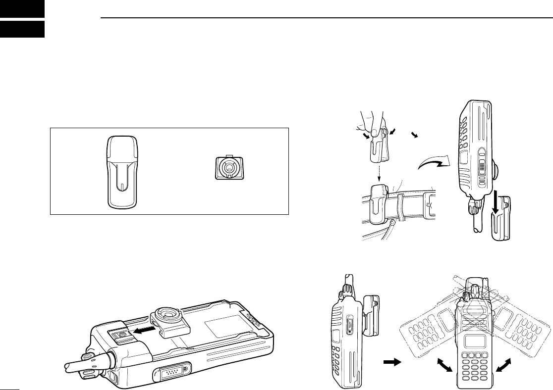
8SWIVEL BELT CLIP
■MB-93 contents
Qty.
qBelt clip ……………………………………………………… 1
wBase clip …………………………………………………… 1
■To attach
qRelease the battery pack if it is attached. (p. 2)
wSlide the base clip in the direction of the arrow until the
base clip is locked and makes a ‘click’sound.
eClip the belt clip to a part of your belt. And insert the trans-
ceiver into the belt clip until the base clip inserted fully into
the groove.
rOnce the transceiver is locked in place, it swivels as illus-
trated below.
q w
!IC-F70_F80.qxd 04.11.9 0:02 PM Page 36 (1,1)
37
8
SWIVEL BELT CLIP
8
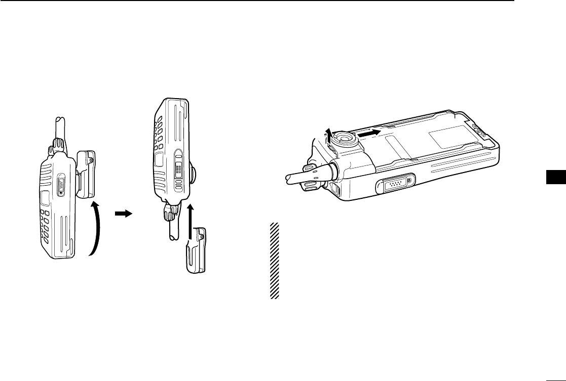
■To detach
qTurn the transceiver upside down in the direction of the
arrow and pull out from the belt clip.
wRelease the battery pack if it is attached. (p. 2)
ePinch the clip (q), and slide the base clip in the direction
of the arrow (w).
CAUTION!
HOLD THE TRANSCEIVER TIGHTLY, WHEN HANGING
OR DETACHING THE TRANSCEIVER FROM THE BELT
CLIP.
Otherwise the transceiver may not be attached to the hold-
er or swivel properly if the transceiver is accidentally
dropped and the base clip is scratched or damaged.
qw
!IC-F70_F80.qxd 04.11.9 0:02 PM Page 37 (1,1)
38
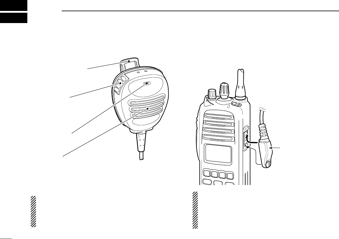
9SPEAKER-MICROPHONE
■Optional HM-138 description
NEVER immerse the connector in water. If the connector
becomes wet, be sure to dry it BEFORE attaching it to the
transceiver.
NOTE: The microphone is located at the top of the
speaker-microphone, as shown in the diagram above. To
maximize the readability of your transmitted signal (voice),
hold the microphone approx. 5 to 10 cm (2 to 4 inches)
from your mouth, and speak in a normal voice level.
■Attachment
Attach the connector of the speaker-microphone into the
[SP/MIC] connector on the transceiver and tighten the screw.
IMPORTANT: KEEP the [SP/MIC] jack cover attached
(transceiver) when the speaker-microphone is not in use.
Water will not get into the transceiver even if the cover is
not attached, however, the terminals (pins) will become
rusty, or the transceiver will function abnormally if the con-
nector becomes wet.
CAUTION: Attach the
speaker-microphone s
connector securely to
prevent accidental
dropping, or water intru-
sion in the connector.
Alligator type clip
To attach the speaker-mic.
to your shirt or collar, etc.
PTT switch
Transmits while pushed
Receives while released
Microphone
Speaker
!IC-F70_F80.qxd 04.11.9 0:02 PM Page 38 (1,1)

39
10
OPTIONS
9
10
DBATTERY PACK
•BP-235 Li-Ion
BATTERY PACK
7.4 V/1600 mAh Li-Ion battery pack, allows more than 8
hours operation. The same as supplied with the transceiver.
•BP-236 Li-Ion
BATTERY PACK
7.4 V/2400 mAh Li-Ion battery pack, allows more than 12
hours operation.
•BP-237
BATTERY CASE
Battery case for 6 ×AA (LR6) alkaline cells.
DCHARGERS
•BC-119N
DESKTOP CHARGER
+ AD-110
CHARGER ADAPTER
+ BC-145
AC ADAPTER
For rapid charging of battery packs. An AC adapter is sup-
plied with the charger depending on versions. Charging
time: approx. 2 hours when BP-235 is attached.
•BC-121N
MULTI
-
CHARGER
+ AD-110
CHARGER ADAPTER
(6
pcs.)
+ BC-124
AC ADAPTER
For rapid charging of up to 6 battery packs (six AD-100’s are
required) simultaneously. An AC adapter should be pur-
chased separately. Charging time: approx. 2 hours when
BP-235 is attached.
DBELT CLIPS
•MB-93
SWIVEL BELT CLIP
•MB-94
BELT CLIP
Exclusive alligator-type belt clip. The same as supplied with
the transceiver.
•MB-96N/96F
LEATHER BELT HANGER
DOPTIONAL UNITS
• UT-109 (#02)/UT-110 (#02)
SCRAMBLER UNITS
Non-rolling type (UT-109)/Rolling type (UT-110) voice
scrambler unit provides higher communication security.
• UT-111
LTR TRUNKING BOARD
Provides trunking operation.
DDC CABLES
•CP-17L
CIGARETTE LIGHTER CABLE
Allows charging of the battery pack through a 12 V cigarette
lighter socket. (For BC-119N)
•OPC-515L/OPC-656
DC POWER CABLES
Allows charging of the battery pack using a 13.8 V power
source instead of the AC adapter.
OPC-515L: For BC-119N
OPC-656 : For BC-121N
•OPC-966
INTERFACE CABLE
Provides advanced operation, such as printer, GPS con-
nection for position data transmission capabilities during
BIIS operation.
!IC-F70_F80.qxd 04.11.9 0:02 PM Page 39 (1,1)

40
10OPTIONS
DOTHER OPTIONS
•HM-138
SPEAKER
-
MICROPHONE
Full-sized waterproof (JIS grade 7; 1m/30 min.) speaker-
microphone including alligator type clip to attach to your shirt
or collar, etc.
•HS-94/HS-95/HS-97
HEADSET
+ VS-1SC
VOX
/
PTT CASE
HS-94: Ear-hook type
HS-95: Neck-arm type
HS-97: Throat microphone
VS-1SC: VOX/PTT switch box for hands-free operation, etc.
•FA-SC25V/FA-SC55V/FA-SC25U/FA-SC57U/FA-SC72U
FLEXIBLE ANTENNAS
FA-SC25V: 136–155 MHz FA-SC55V: 146–174 MHz
FA-SC25U: 400–430 MHz FA-SC57U: 440–470 MHz
FA-SC72U: 470–520 MHz
•FA-SC56VS/FA-SC57VS/FA-SC73US
STUBBY ANTENNAS
FA-SC56VS: 150–162 MHz FA-SC57VS: 160–174 MHz
FA-SC73US: 450–490 MHz
Some options may not available in some countries. Please ask your
dealer for details.
ïAbout VS-1SC
VOX
/
PTT CASE
The VS-1SC is a VOX/PTT unit for Icom handheld trans-
ceivers, and allows you hands-free operation.
An optional headset (HS-94, etc.) is additionally required for
operation.
• The VOX (voice operated transmission) function starts transmission
without pushing PTT switch when you speak into the microphone;
then, automatically returns to receive when you stop speaking.
Features
➥9-pin Spring-plug type head SP/MIC plug is equipped
➥Water resistant construction
➥Durable construction
➥Equipped with a PTT switch and revolving clip
VS-1SC
VOX
PTT
Adjusting pot
Water protection cover
PTT switch
!IC-F70_F80.qxd 04.11.9 0:02 PM Page 40 (1,1)

41
10
OPTIONS
10
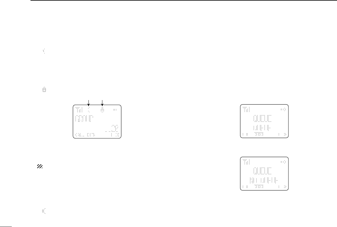
VOX gain and delay adjustment
qAttach the connector of the VS-1SC into the [SP/MIC] con-
nector on the transceiver and tighten the screw.
• Toggle the toggle switch to [VOX].
wEnter user set mode. (p. 17)
ePush [P0] several times to select the “VOX Gain” or “VOX
Delay” items. Then, push [Up] or [Down] to set the desired
level/condition.
rRotate [VOL] to turn the power OFF to exit set mode.
• VOX Gain
The VOX sensitivity level can be adjusted from OFF or 1 to 6.
• VOX Delay
The VOX delay time can be set from 0.5 to 3.0 sec. (0.5 sec.
step) for a convenient interval before returning to receive.
NOTE: MIC/VOX gain can be adjusted via the Adjusting
pot using a thin screw driver.
0.5 sec (min.)
XTXC
SET
3.0 sec (max.)
XTXC
SET
[Up]
Push
[Down]
VOX function is OFF
XTXC
SET
VOX gain level 3
XTXC
SET
[Up]
Push
[Down]
!IC-F70_F80.qxd 04.11.9 0:02 PM Page 41 (1,1)

42
11 SAFETY TRAINING INFORMATION
Your Icom radio generates RF electromagnetic
energy during transmit mode. This radio is
designed for and classified as “Occupational
Use Only”, meaning it must be used only during
the course of employment by individuals aware
of the hazards, and the ways to minimize such
hazards. This radio is NOT intended for use by the “General
Population” in an uncontrolled environment.
This radio has been tested and complies with the FCC RF
exposure limits for “Occupational Use Only”. In addition, your
Icom radio complies with the following Standards and
Guidelines with regard to RF energy and electromagnetic
energy levels and evaluation of such levels for exposure to
humans:
• FCC OET Bulletin 65 Edition 97-01 Supplement C,
Evaluating Compliance with FCC Guidelines for Human
Exposure to Radio Frequency Electromagnetic Fields.
• American National Standards Institute (C95.1-1992),
IEEE Standard for Safety Levels with Respect to Human
Exposure to Radio Frequency Electromagnetic Fields, 3
kHz to 300 GHz.
• American National Standards Institute (C95.3-1992),
IEEE Recommended Practice for the Measurement of
Potentially Hazardous Electromagnetic Fields– RF and
Microwave.
• The accessories (antennas, batteries, belt clips, speaker-
microphone, etc. that is listed on Pages 39–40) are
authorized for use with this product. Use of accessories
other than those specified may result in RF exposure lev-
els exceeding the FCC requirements for wireless RF
exposure.
To ensure that your expose to RF electro-
magnetic energy is within the FCC allow-
able limits for occupational use, always
adhere to the following guidelines:
• DO NOT operate the radio without a proper antenna
attached, as this may damaged the radio and may also
cause you to exceed FCC RF exposure limits. A proper
antenna is the antenna supplied with this radio by the
manufacturer or antenna specifically authorized by the
manufacturer for use with this radio.
• DO NOT transmit for more than 50% of total radio use
time (“50% duty cycle”). Transmitting more than 50% of
the time can cause FCC RF exposure compliance
requirements to be exceeded. The radio is transmitting
when the TX indicator lights red. You can cause the radio
to transmit by pressing the “PTT” switch or VOX function.
• ALWAYS keep the antenna at least 2.5 cm (1 inch) away
from the body when transmitting and only use the Icom
belt-clips listed on page 39 when attaching the radio to
your belt, etc., to ensure FCC RF exposure compliance
requirements are not exceeded. To provide the recipients
of your transmission the best sound quality, hold the
antenna at least 5 cm (2 inches) from your mouth, and
slightly off to one side.
The information listed above provides the user with the infor-
mation needed to make him or her aware of RF exposure,
and what to do to assure that this radio operates with the
FCC RF exposure limits of this radio.
CAUTION
WARNING
!IC-F70_F80.qxd 04.11.9 0:02 PM Page 42 (1,1)

43
11
SAFETY TRAINING INFORMATION
11
Electromagnetic Interference/Compatibility
During transmissions, your Icom radio generates RF energy
that can possibly cause interference with other devices or
systems. To avoid such interference, turn off the radio in
areas where signs are posted to do so. DO NOT operate the
transmitter in areas that are sensitive to electromagnetic radi-
ation such as hospitals, aircraft, and blasting sites.
Occupational/Controlled Use
The radio transmitter is used in situations in which persons
are exposed as consequence of their employment provided
those persons are fully aware of the potential for exposure
and can exercise control over their exposure.
!IC-F70_F80.qxd 04.11.9 0:02 PM Page 43 (1,1)

1-1-32 Kamiminami, Hirano-ku, Osaka 547-0003, Japan
A-6418D-1US
Printed in Japan
© 2004 Icom Inc.
!IC-F70_F80.qxd 04.11.9 0:02 PM Page Z (1,1)