ICOM orporated 280402 UHF-FM Hand Held Transceiver User Manual IC F70 F80
ICOM Incorporated UHF-FM Hand Held Transceiver IC F70 F80
UserManual.wiki
>
ICOM orporated
>
280402 User Manual
Manual
Navigation menu
Upload a User Manual
Namespaces
Wiki Guide
HTML
PDF
Info
Views
User Manual
Discussion / Help
Navigation
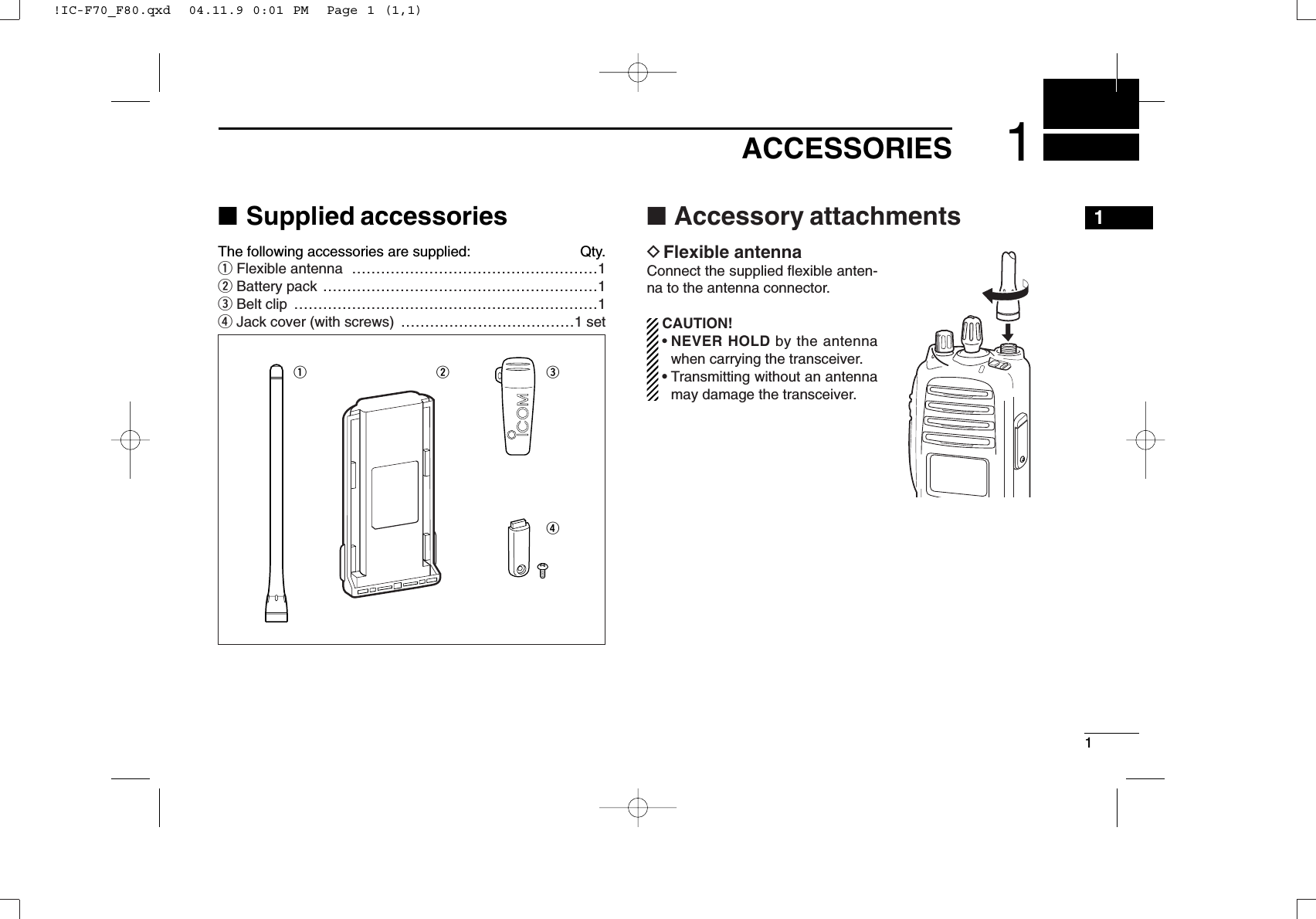
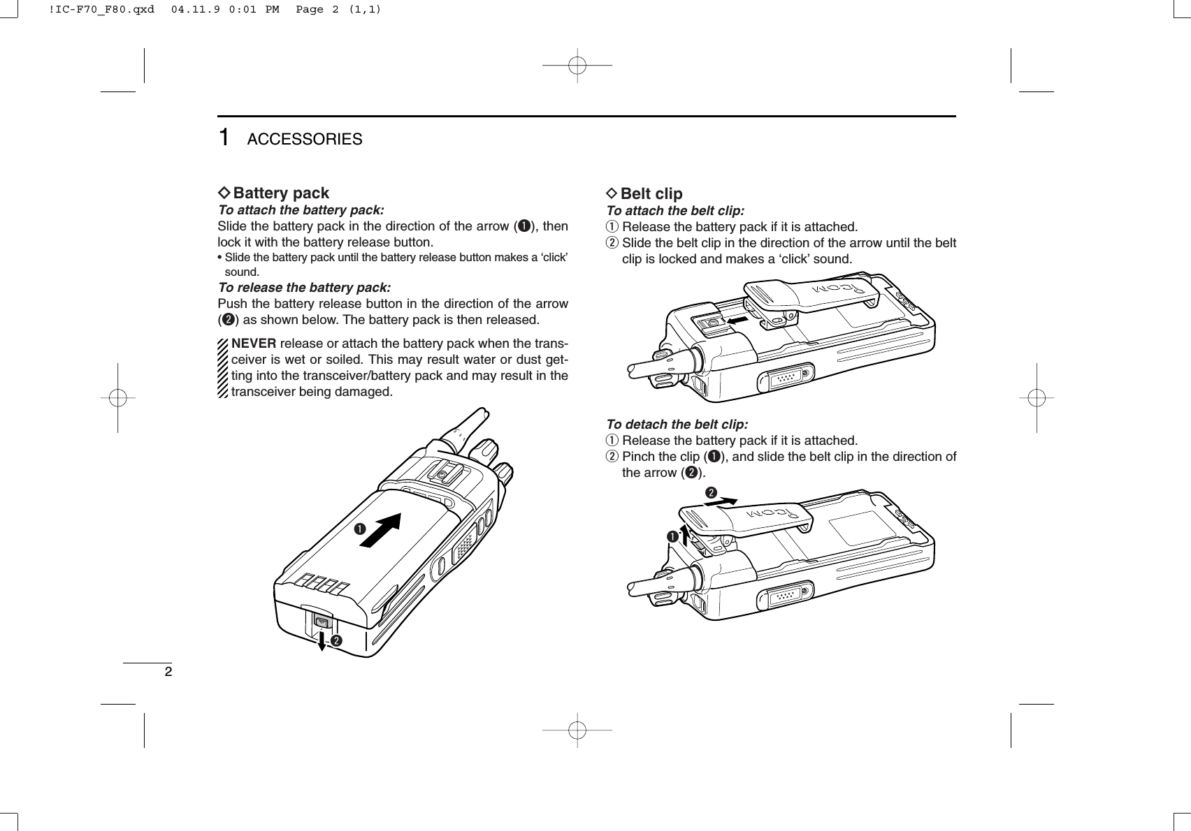
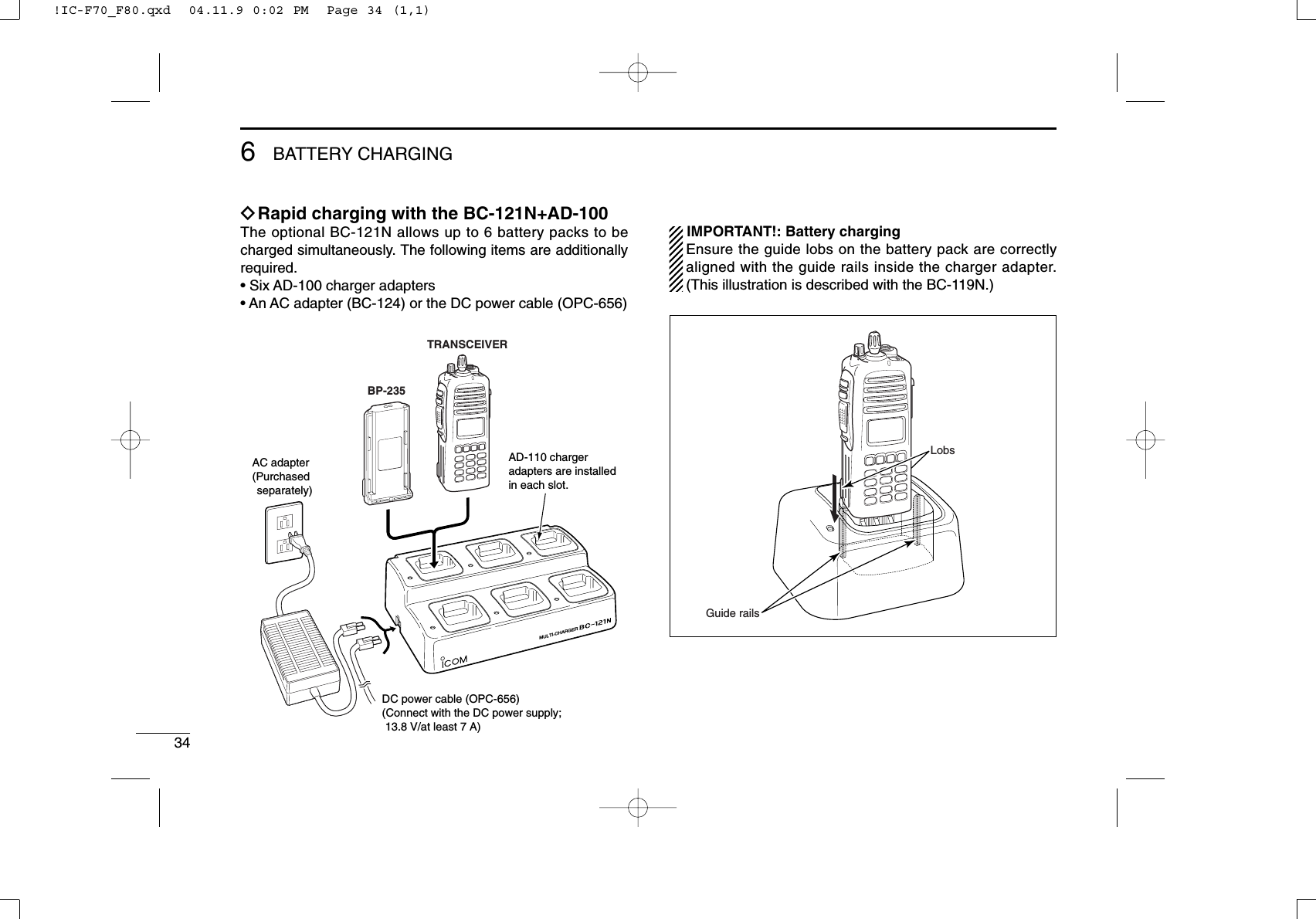
![31ACCESSORIES1ïJack coverAttach the jack cover when the optional speaker-microphoneis not used.qwerTo attach the jack cover:qInsert the jack cover intothe [SP MIC] connector.wTighten the screw.To detach the jack cover:eUnscrew the screw with aphillips screwdriver.rDetach the jack cover forthe speaker-microphoneconnection.!IC-F70_F80.qxd 04.11.9 0:01 PM Page 3 (1,1)](https://usermanual.wiki/ICOM-orporated/280402/User-Guide-500789-Page-7.png)
![42PANEL DESCRIPTION■Front panelqVOLUME CONTROL [VOL]Rotate to turn the power ON/OFF and adjusts the audiolevel.wROTARY SELECTORRotate to select the pre-programmed memory channels orthe operating bank.(Depending on the pre-setting)eANTENNA CONNECTORConnects the supplied antenna.rEMERGENCY SWITCHPush and hold for a specified period to transmit an emer-gency call.*Desired function can be programmed by your dealer. (p. 7)tBUSY/TRANSMIT INDICATOR➥ Lights green while receiving a signal, or when thesquelch is open.➥ Lights red while transmitting.y[SP/MIC] JACKConnect the optional speaker-microphone.uFUNCTION DISPLAY (p. 6)Displays a variety of information, such as an operatingchannel number/name, 5-tone code, DTMF numbers andaudible condition, etc.iDEALER-PROGRAMMABLE KEYSDesired functions can be programmed independently byyour dealer. (p. 7)[SP/MIC] jack coverNOTE: Attach the [SP/MIC] jack cover when the optional speaker-microphone is not used. (See p. 3 for details)q!2!1!0wertSpeakeroyui!IC-F70_F80.qxd 04.11.9 0:01 PM Page 4 (1,1)](https://usermanual.wiki/ICOM-orporated/280402/User-Guide-500789-Page-8.png)
![52PANEL DESCRIPTION2o10-KEYPAD (IC-F70DT/F70T or IC-F80DT/F80T only)The keypad allows you to enter digits to:• Select memory channels, tone channels and DTMF codes(when in the DTMF code channel selection mode)• Set TX codes and BIIS status number• Input text message for SDM operation• Start up with a password• Input the Individual ID code for digital operation.!0 MONITOR SWITCH➥ Mute and release the CTCSS (DTCS) or 2-tone squelchmute. Open any squelch/deactivate any mute whilepushing this key. (LMR operation only)➥ Activates one of (or two of) the following functions oneach channel independently.(PMR or BIIS PMR operation only)• Push and hold the key to unmute the channel (audio isemitted; ‘audible’condition).• Push the key to toggle the mute and unmute conditions(toggles ‘audible’and ‘inaudible’).• Push the key to mute the channel (sets to ‘inaudible’only).• Push the key to unmute the channel (sets to ‘audible’only).• Push the key after communication is finished to send a ‘resetcode.’• Push the key after communication is finished to send a ‘cleardown code’during BIIS operation on an MSK channel.NOTE: The unmute condition (‘audible’conditions)may automatically return to the mute condition(‘inaudible’condition) after a specified period.*Desired function can be programmed by your dealer. (p. 7)!1 PTT SWITCH [PTT]➥Push and hold to transmit; release to receive.➥Push to transmit the call during MSK operation, depend-ing on the setting.!2 UP/DOWN SWITCHES➥Push to select an operating channel.➥Push to select a TX code channel after pushing [TX CODE CH SELECT].➥Push to select a DTMF channel after pushing [DTMF].➥Push to select a scan group after pushing and holding[SCAN].➥Push to select a BIIS code, status number or SDM afterpushing [DIGITAL].*Desired functions can be programmed independently by yourdealer. (p. 7)!IC-F70_F80.qxd 04.11.9 0:01 PM Page 5 (1,1)](https://usermanual.wiki/ICOM-orporated/280402/User-Guide-500789-Page-9.png)
![62PANEL DESCRIPTION■Function displayqSIGNAL STRENGTH INDICATORIndicates relative signal strength level.wLOW POWER INDICATORAppears when low output power is selected.eAUDIBLE INDICATOR➥Appears when the channel is in the ‘audible’(unmute)condition.➥Appears when the specified 2/5-tone/BIIS code isreceived.rCOMPANDER INDICATORAppears when the compander function is activated.tSCRAMBLER INDICATORAppears when the voice scrambler function is activated.yBELL INDICATORAppears/blinks when the specific 2/5-tone/BIIS code isreceived, according to the pre-programming.uCALL CODE MEMORY INDICATORAppears when the call code memory is selected.iSCROLL INDICATORAppears when a received SDM including more than 12characters is displayed.oBATTERY INDICATORAppears or blinks when the battery power decreases to aspecified level.!0 ALPHANUMERIC DISPLAYDisplays an operating channel number, channel name, Setmode contents, DTMF code, etc. The indication mode can be selected from 1 line or 2 lines.Ask your dealer for details.In this instruction manual, the LCD illustration is describedusing the 2 lines indication mode.!1 KEY INDICATORIndicate the programmed function of the front panel keys([P0], [P1], [P2] and [P3]).XTXC SETq t oiuyrew!0!1!IC-F70_F80.qxd 04.11.9 0:02 PM Page 6 (1,1)](https://usermanual.wiki/ICOM-orporated/280402/User-Guide-500789-Page-10.png)
![72PANEL DESCRIPTION■Programmable function keysThe following functions can be assigned to [DIAL]*, [UP],[DOWN], [P0], [P1], [P2] and [P3] programmable functionkeys.Consult your Icom dealer or system operator for details con-cerning your transceivers programming.If the programmable function names are bracketed in the fol-lowing explanations, the specific key is used to activate thefunction depends on the programming.CH UP AND DOWN KEYS “UP” “DOWN”➥Push to select an operating channel.➥Push to select a transmit code channel after pushing [TXCode CH Select].➥Push to select a DTMF channel after pushing [DTMFAutodial].➥Push to select a scan group after pushing and holding[Scan A Start/Stop]/[Scan B Start/Stop].➥Push to select a BIIS code, status number or SDM afterpushing [Digital].➥Push to select an Individual ID code or Talkgroup ID codeafter pushing [Individual] or [Talkgroup].ZONE SELECT KEY “ZONE”Push this key, then select the desired zone using [CH Up]/[CH Down].What is “zone”?— The desired channels are assignedinto a zone according to the intended use. For example,‘Staff A’and ‘Staff B’are assigned into a “Business” zone,and ‘John’and ‘Cindy’are assigned into a “Private” zone.SCAN A KEY “SCNA”➥This key’s operation depends on the Power ON Scan setting.When the power ON scan function is turned OFF;Push to start and cancel scanning operation. In case oftransmission during scan, cancels scanning.When the power ON scan function is turned ON;Push to pause scanning. Scanning resumes after a speci-fied time period has passed. In case of transmission duringscan, pauses scanning. Scanning resumes after a specifiedtime period has passed after the transmission is finished.➥Push and hold this key for 1 sec. to indicate the scan group,then select the desired group using [CH Up]/[CH Down].SCAN B KEY “SCNB”➥Push to start and cancel scanning operation. In case oftransmission during scan, pauses scanning. Scanningresumes after a specified time period has passed after thetransmission is finished.➥Push and hold this key for 1 sec. to indicate the scangroup, then select the desired group using [CH Up]/[CH Down].2!IC-F70_F80.qxd 04.11.9 0:02 PM Page 7 (1,1)](https://usermanual.wiki/ICOM-orporated/280402/User-Guide-500789-Page-11.png)
![82PANEL DESCRIPTIONSCAN TAG KEY “SCAD”Push to add or delete the selected channel to/from the scangroup.PRIORITY CHANNEL KEYS “PRA”/“PRAR”/“PRB”/“PRAR”➥Push to select Priority A or Priority B channel.➥Push and hold [Prio A (Rewrite)] to rewrite the Prio A chan-nel.MR-CH 1/2/3/4 KEYS “CH1”/“CH2”/“CH3”/“CH4”Push to select an operating channel directly.MONITOR KEY “MON”➥Mute and release the CTCSS (DTCS) or 2-tone squelchmute. Open any squelch/deactivate any mute while push-ing this key. (LMR operation only)➥Activates one of (or two of) the following functions on eachchannel independently: (PMR or BIIS PMR operation only)• Push and hold to un-mute the channel (audio is emitted; ‘Audible’condition).• Push to mute the channel (sets to ‘Inaudible’only).• Push to un-mute the channel (sets to ‘Audible’only).• Push after the communication is finished to send a ‘reset code’.NOTE: The un-mute condition (‘Audible’condition) mayautomatically return to the mute condition (‘Inaudible‘ con-dition) after a specified period depending on programming.LIGHT KEY “LAMP”Push to turn the transceiver’s backlight ON temporarily whenthe backlight function is turned OFF in user set mode.LOCK KEY “LOCK”Push and hold to electronically lock all programmable keysexcept the following:[Call] (incl. Call A and Call B), [Moni(Audi)] and [Emergency].OUTPUT POWER SELECTION KEY “H/L”Push to select the transmit output power temporarily or per-manently, depending on the pre-setting.•Ask your dealer for the output power level for each selection.C.TONE CHANNEL ENTER KEY “TSEL”Push to select the continuous tone channel using [CH Up]/[CH Down] to change the tone frequency/code setting. Theselected channel remains set as the continuous tone chan-nel until another channel is designated as such.TALK AROUND KEY “TA”Turn the talk around function ON and OFF.•The talk around function equalizes the transmit frequency to thereceive frequency for transceiver-to-transceiver communication.WIDE/NARROW KEY “W/N”Push to toggle the IF bandwidth between wide and narrow.• The wide passband width can be selected from 25.0 or 20.0 kHzusing the CS-F70/F1700 CLONING SOFTWARE. (PMR or BIIS PMRoperation only) Ask your Dealer for details.!IC-F70_F80.qxd 04.11.9 0:02 PM Page 8 (1,1)](https://usermanual.wiki/ICOM-orporated/280402/User-Guide-500789-Page-12.png)
![92PANEL DESCRIPTIONDTMF AUTODIAL KEY “DTMA”➥Push to enter the DTMF channel selection mode. Thenselect the desired DTMF channel using [CH Up]/[CH Down].➥After selecting the desired DTMF channel, push this key totransmit the DTMF code.DTMF RE-DIAL KEY “DTMR”Push to transmit the last-transmitted DTMF code.CALL KEYS “CALL”/“CALA”/“CALB”Push to transmit a 2/5-tone/BIIS ID code.•Call transmission is necessary before calling another stationdepending on your signalling system.•[Call A] and/or [Call B] may be available when your system employsselective ‘Individual/Group’calls. Ask your dealer which call isassigned to each key.EMERGENCY KEYS “EMGS”/“EMSS”/“EMGR”/“EMRS”➥Push and hold for a specified period to transmit an emer-gency call.➥When [Emergency Single (Silent)] or [Emergency Repeat(Silent)] is pushed, an emergency call is transmitted withouta beep emission and LCD indication change.• If you want to cancel the emergency call, push (or push andhold) the key again before transmitting the call.• The emergency call is transmitted one time only or repeatedlyuntil receiving a control code depending on the pre-setting.SURVEILLANCE KEY “SURV”Push to turn the surveillance function ON or OFF.When this function is turned ON, the beep is not emitted andthe LCD backlight does not light when a signal is received ora key is pushed, etc.TX CODE ENTER KEY “TXCE”(PMR or BIIS PMR operation only)Push to enter the ID code edit mode directly, for both 5-toneand MSK. Then set the desired digit using [CH Up]/[CH Down] or 10-keypad*. (p. 15)*IC-F70DT/T or IC-F80DT/T onlyTX CODE CHANNEL SELECT KEY “TXC”➥Push to enter the ID code channel selection mode directly.Then set the desired channel using [CH Up]/[CH Down]. (p. 14)➥During ID code channel selection mode, push for 1 sec. toenter the ID code edit mode for 5-tone and MSK. Then setthe desired digit using [CH Up]/[CH Down] or 10-keypad*.(p. 15)*IC-F70DT/T or IC-F80DT/T onlyTX CODE CHANNEL UP/DOWN KEYS “TXCU”/“TXCD”Push to select a TX code channel directly.2!IC-F70_F80.qxd 04.11.9 0:02 PM Page 9 (1,1)](https://usermanual.wiki/ICOM-orporated/280402/User-Guide-500789-Page-13.png)
![102PANEL DESCRIPTIONID MEMORY READ KEY “IDMS”(PMR or BIIS PMR operation only)➥Recalls detected ID codes.•Push this key, then select the ID code using [CH Up]/[CH Down].•Up to 5 ID’s are memorized.➥Push and hold to erase the selected ID’s.VOICE SCRAMBLER FUNCTION “SCR”Push to toggle the voice scrambler function ON and OFF.COMPANDER KEY “COMP”Push to toggle the compander function ON and OFF. The compander function reduces noise components from thetransmitted audio to provide clear communication.USER SET MODE KEY “SET”➥Push and hold to enter user set mode.• During user set mode, push this key to select an item, andchange the value or condition using push [CH Up]/[CH Down].➥Push and hold this key again to exit user set mode.User set mode is also available via the ‘Power ON function.’Refer to p. 17 also.OPT OUT KEYS “OP1”/“OP2”/“OP3”Push to control the output signal level from the optional unitconnector.DIGITAL KEY “BIFN”(BIIS operation only)➥Push to select the call ID list, transmit message and stand-by condition. Toggles between queue channel andreceived message record indication after queue channel isselected.➥Push and hold to select queue channel indication.STATUS UP/DOWN KEYS “BIUP”/“BIDN”(BIIS operation only)➥While in the standby condition, push to display the trans-mit status indication and select a status number.➥When a received SDM is displayed, push to cancel theautomatic scroll and scroll the message manually.➥When an SDM that contains more than 12 characters isdisplayed, push to scroll the message manually.TONE/NAC CH SELECT KEY “TSEL”➥While in the analog mode operation, push to select thecontinuous tone channel using [CH Up] or [CH Down] tochange the tone frequency/code setting.➥While in the digital mode operation, push to select the NACchannel using [CH Up] or [CH Down] to change the NACcode setting.➥While in the mixed (digital and analog) mode operation,push to select the continuous tone channel using [CH Up]or [CH Down] to change the tone frequency/code setting.Then push this key to enter the setting. After that, the NACchannel selection screen appears. Select the NAC chan-nel using [CH Up] or [CH Down] to change the NAC codesetting. Then push this key to enter the setting.!IC-F70_F80.qxd 04.11.9 0:02 PM Page 10 (1,1)](https://usermanual.wiki/ICOM-orporated/280402/User-Guide-500789-Page-14.png)
![112PANEL DESCRIPTION2DFor Digital mode operation onlyINDIVIDUAL KEY “INDV”➥Push to enter the individual ID code selection mode directly.Then select the desired individual ID code using [CH Up]/[CH Down]. (p. 16)➥Push to stop the beep emission when receiving a matchedindividual ID code.TALKGROUP KEY “TGID”➥Push to enter the talkgroup ID code selection mode directly.Then select the desired talkgroup ID code using [CH Up]/[CH Down]. (p. 16)➥Push to stop the beep emission when receiving a matchedtalkgroup ID code.!IC-F70_F80.qxd 04.11.9 0:02 PM Page 11 (1,1)](https://usermanual.wiki/ICOM-orporated/280402/User-Guide-500789-Page-15.png)
![123BASIC OPERATION■Turning power ONqRotate [VOL] to turn the power ON.wIf the transceiver is programmed for a start up password,input the digit codes as directed by your dealer.• 10-keypad* can be used for password input.*IC-F70DT/T or IC-F80DT/T only:• The keys as below can be used for password input:The transceiver detects numbers in the same block as identical.Therefore “01234” and “56789” are the same.eWhen the “PASSWORD” indication does not clear afterinputting 6 digits, the input code number may be incorrect.Turn the power off and start over in this case.■Channel selectionSeveral types of channel selections are available. Methodsmay differ according to your system set up.NON-ZONE TYPE:Push [CH Up] or [CH Down], or rotate [ROTARY SELECTOR]*to select the desired operating channel, in sequence; or, pushone of [MR-CH 1] to [MR-CH 4] keys to select a channeldirectly.• Up to 16 pre-programmed channels can be selected via [ROTARYSELECTOR].ZONE TYPE:Push [Zone] then push [CH Up] or [CH Down] or rotate[ROTARY SELECTOR]* to select the desired zone.AUTOMATIC SCAN TYPE:Channel setting is not necessary for this type. When turningpower ON, the transceiver automatically starts scanning.Scanning stops when receiving a call.*Depending on the pre-setting.KEYNUMBER 0549382716[MONI][P0]/[P1]/[P2]/[P3]MONI!IC-F70_F80.qxd 04.11.9 0:02 PM Page 12 (1,1)](https://usermanual.wiki/ICOM-orporated/280402/User-Guide-500789-Page-16.png)
![133BASIC OPERATION3■Call procedureWhen your system employs tone signaling (excluding CTCSSand DTCS), the call procedure may be necessary prior to voicetransmission. The tone signalling employed may be a selec-tive calling system which allows you to call specific station(s)only and prevent unwanted stations from contacting you.qSelect the desired TX code channel, 2/5-tone code,Individual ID code* or Talkgroup ID code* according toyour System Operator’s instructions.• This may not be necessary depending on programming.• Refer to pgs. 14–16 for selection.*Digital mode operation only.wPush the call key (assigned to one of the dealer program-mable keys; except for the Digital mode operation) or [PTT].eAfter transmitting, the remainder of your communicationcan be carried out in the normal fashion.■Receiving and transmittingReceiving:qRotate [VOL] to turn the power ON.wPush [CH Up] or [CH Down], or rotate [ROTARY SELEC-TOR]* to select a channel in sequence.*Depending on the pre-setting.eWhen receiving a call, adjust the audio output level to acomfortable listening level.Transmitting:Wait for the channel to become clear to avoid interference.qPush [CALL] when initiating a call from your side.• Coded audio may be heard from the transceiver, then “”appears.• This operation may not be necessary depending on your signal-ing system. Ask your dealer for details.wWhile pushing and holding [PTT], speak into the micro-phone at your normal voice level.eRelease [PTT] to return to receive.IMPORTANT: To maximize the readability of your signal;1. Pause briefly after pushing [PTT].2. Hold the microphone 5 to 10 cm (2 to 4 inches) fromyour mouth, then speak into the microphone at a normalvoice level.Selective calling Non-selective calling!IC-F70_F80.qxd 04.11.9 0:02 PM Page 13 (1,1)](https://usermanual.wiki/ICOM-orporated/280402/User-Guide-500789-Page-17.png)
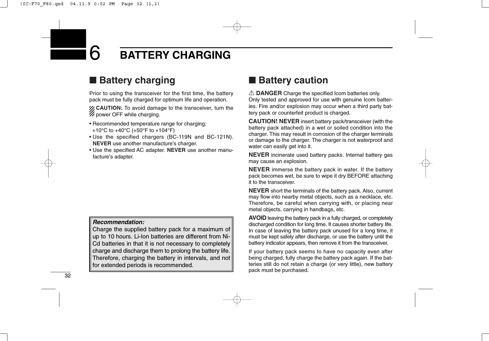
![143BASIC OPERATIONDTransmitting notes• Transmit inhibit functionThe transceiver has several inhibit functions which restricttransmission under the following conditions:- The channel is in mute condition (‘Inaudible’condition; “”does not appear.)- The channel is busy.- Un-matched (or matched) CTCSS is received.(Depending on the pre-setting.)- Un-matched (or matched) NAC is received.*(Depending on the pre-setting.)- Un-matched (or matched) Individual ID or Talkgroup ID isreceived.*- The selected channel is a ‘receive only’channel.*Digital mode operation only.• Time-out timerAfter continuous transmission for the pre-programmed timeperiod, the time-out timer is activated, causing the transceiv-er to stop transmitting.• Penalty timerOnce the time-out timer is activated, transmission is furtherinhibited for a period determined by the penalty timer.DTX code channel selectionIf the transceiver has [TX Code CH Select] assigned to it, theindication can be toggled between the operating channelnumber (or name) and TX code channel number (or name).When the TX code channel number (or name) is displayed,[CH Up]or [CH Down] selects the TX code channel.USING [TX CODE CH SELECT] KEY:qPush [TX Code CH Select]—a TX code channel number(or name) appears.wPush [CH Up] or [CH Down] to select the desired TX codechannel.ePush [Call] (or [PTT] during MSK operation) to transmit theselected TX code.USING [TX CODE CH UP]/[TX CODE CH DOWN] KEY:If the transceiver has a [TX Code CH Up] or [TX Code CHDown] key assignment, the programmed TX code channelcan be selected directly when pushed.NOTE for PMR or BIIS PMR operation:• The LCD indication does not change when the operatingchannel number (or name) is displayed.• To check the selected TX code, push [TX Code CHSelect].!IC-F70_F80.qxd 04.11.9 0:02 PM Page 14 (1,1)](https://usermanual.wiki/ICOM-orporated/280402/User-Guide-500789-Page-18.png)
![153BASIC OPERATIONDTX code number edit(PMR or BIIS PMR operation only)If the transceiver has [TX Code CH Select] or [TX CodeEnter] assigned to it, TX code contents can be edited withinthe allowable digits.USING [TX CODE CH SELECT] KEY:qPush [TX Code CH Select] to enter the TX code channelselection mode.• Select the desired channel before entering the TX code channelselection mode if necessary.wPush [TX Code CH Select] for 1 sec. to enter the TX codeedit mode.ePush [TX Code CH Select] to select the desired digit to beedited.• The digit to be edited blinks.rPush [CH Up], [CH Down] or 10-keypad* to set the desireddigit.tPush [TX Code CH Select] to set the digit. The digit to theright will blink automatically.• When the 10-keypad* is used for setting, the digit to the right willblink automatically without pushing [TX Code CH Select].yRepeat rand tto input all allowable digits.uPush [Call] or [PTT] to transmit the edited TX code.*IC-F70DT/T or IC-F80DT/T onlyUSING [TX CODE ENTER] KEY:qSelect the desired TX code channel via [TX Code CHSelect]+[CH Up] or [CH Down], [TX Code CH Up] or [TXCode CH Down].wPush [TX Code Enter] to enter the TX code edit mode.ePush [TX Code Enter] to select the desired digit to be edit-ed.• The digit to be edited blinks.rPush [CH Up], [CH Down] or 10-keypad* to set the desireddigit .tPush [TX Code Enter] to set the digit. The digit to the rightwill blink automatically.• When the 10-keypad* is used for setting, the digit to the right willblink automatically without pushing [TX Code CH Enter].yRepeat rand tto input all allowable digits.uPush [Call] or [PTT] to transmit the edited TX code.*IC-F70DT/T or IC-F80DT/T only3!IC-F70_F80.qxd 04.11.9 0:02 PM Page 15 (1,1)](https://usermanual.wiki/ICOM-orporated/280402/User-Guide-500789-Page-19.png)
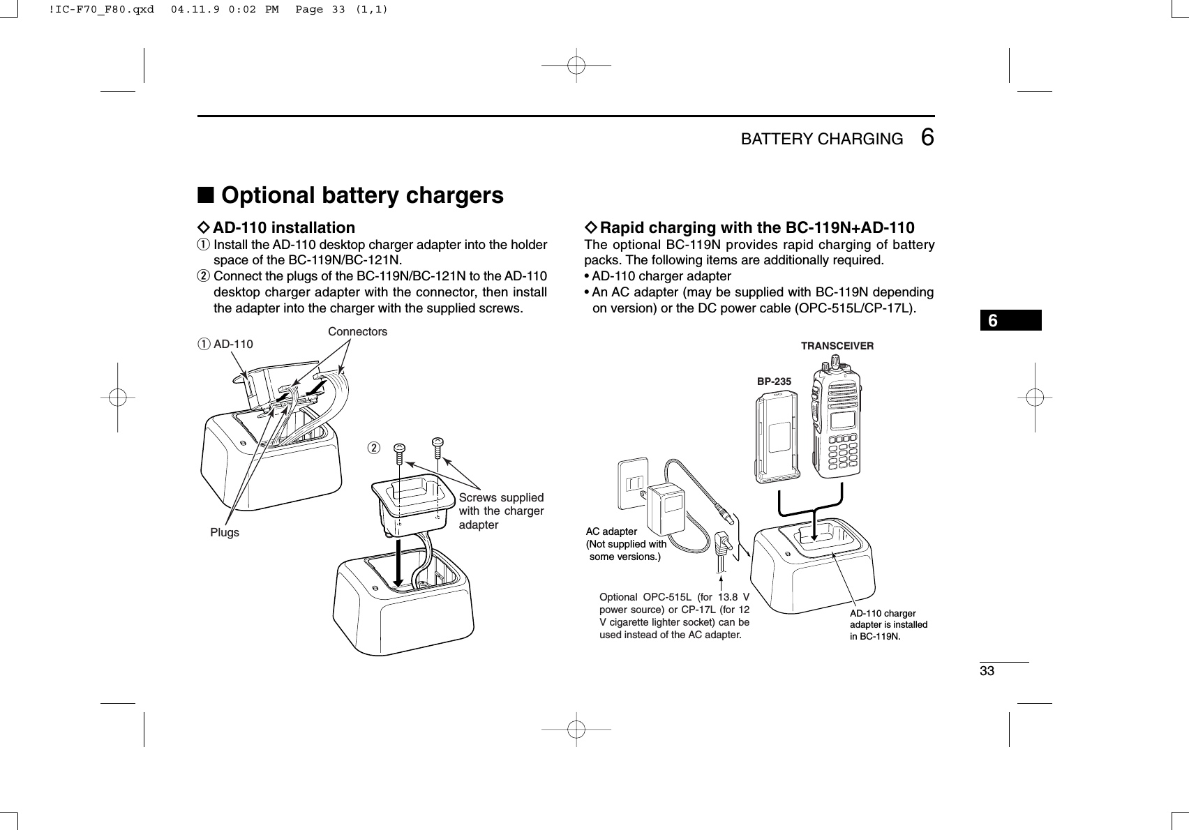
![163BASIC OPERATIONDIndividual ID code selection(Digital mode operation only)If the transceiver has [Individual] assigned to it, the indicationcan be toggled between the operating channel number (orname) and Individual ID code (or name). When the IndividualID code (or name) is displayed, [CH Up] or [CH Down] selectsthe desired Individual ID code.qPush [Individual]—an Individual ID code (or name)appears.wPush [CH Up] or [CH Down] to select the desiredIndividual ID code.ePush [PTT] to transmit the selected Individual ID code.rPush [Individual]—cancels the selected Individual ID code(return to the pre-set Talkgroup ID code in the channel.)DTalkgroup ID code selection(Digital mode operation only)If the transceiver has [Talkgroup] assigned to it, the indicationcan be toggled between the operating channel number (orname) and Talkgroup ID code (or name). When the TalkgroupID code (or name) is displayed, [CH Up] or [CH Down] selectsthe desired Talkgroup ID code.qPush [Talkgroup]—a Talkgroup ID code (or name)appears.wPush [CH Up] or [CH Down] to select the desiredTalkgroup ID code.ePush [PTT] to transmit the selected Talkgroup ID code.rChange the channel—cancels the selected Talkgroup IDcode (return to the pre-set Talkgroup ID code in the chan-nel.)DDTMF transmissionIf the transceiver has [DTMF Autodial] assigned to it, theautomatic DTMF transmission function is available. Up to 8DTMF channels are available.TO SELECT A TX CODE:qPush [DTMF Autodial]—a DTMF channel appears.wPush [CH Up] or [CH Down] to select the desired DTMFchannel.ePush [DTMF Autodial] to transmit the DTMF code in theselected DTMF channel.!IC-F70_F80.qxd 04.11.9 0:02 PM Page 16 (1,1)](https://usermanual.wiki/ICOM-orporated/280402/User-Guide-500789-Page-20.png)
![173BASIC OPERATION■User set modeUser set mode is accessed at power ON and allows you toset seldom-changed settings. In this case you can “cus-tomize” the transceiver operation to suit your preferences andoperating style.Entering the user set mode:qWhile pushing and holding [P1]and [P2], rotate [VOL] to turnthe power ON. Then, push andhold [P0] to enter user setmode.wPush [P0] several times toselect the appropriate item.Then, push [Up] or [Down] toset the desired level/condition.• Available set mode functions areBacklight, LCD Contrast, Beep,Beep Level, SQL Level, AF MinLevel, Mic Gain, Vox Gain, VoxDelay and Battery Voltage.eRotate [VOL] to turn the powerOFF to exit set mode.User set mode is also available viaa programmable key. Please referto p. 10 [User Set Mode] section.[P0][P1]/[P2][VOL][P0][Down][Up][VOL]3!IC-F70_F80.qxd 04.11.9 0:02 PM Page 17 (1,1)](https://usermanual.wiki/ICOM-orporated/280402/User-Guide-500789-Page-21.png)
![183BASIC OPERATION■Scrambler functionThe voice scrambler function provides private communicationbetween stations. The frequency inversion type is equippedto all versions, moreover, the optional Rolling or Non-rollingtype can be available.qPush [Scrambler] to turn the scrambler function ON.• “” appears.wPush [Scrambler] again to turn the scrambler functionOFF.• “” disappears.!IC-F70_F80.qxd 04.11.9 0:02 PM Page 18 (1,1)](https://usermanual.wiki/ICOM-orporated/280402/User-Guide-500789-Page-22.png)
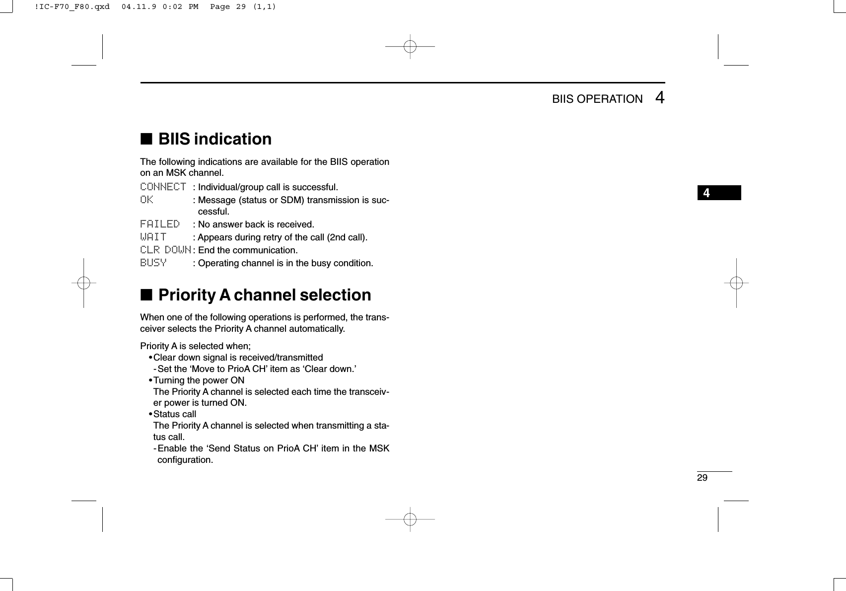
![194BIIS OPERATION34■Default settingThe following functions are assigned to each programmablekey as the default. However, the assigned function can bechanged by your dealer. Ask your dealer for details.During digital mode operation, BIIS is not available.NOTE: [TX Code Enter] must be assigned to a key.[P0]; Call : Push to transmit a 5-tone/BIIS callwhen the selected channel is a 5-toneor MSK channel.• “CALL” is displayed on the key indicator.[P1]; Digital : Push to select the call list ID/transmitmessage, or to display the receivemessage record for selection.• “BIFN” is displayed on the key indicator.[P3]; TX Code Enter : Push to enter the ID code edit modedirectly for both 5-tone and MSK.• “TXCE” is displayed on the key indicator.[P2]; Null : No function is assigned.[MONI]; Moni(Audi) : Push this key after the communica-tion to send a ‘Clear down’signal dur-ing MSK channel operation.[Up]/[Down]; CH Up/Down: While in the standby condition,selects the operating channel.After pushing [Digital] or [TX CodeCH Select], selects call list or TX codechannel, respectively.■Receiving a callDDIndividual callqWhen an individual call is received;•Beeps sound.•“ ” appears and the mute is released.•The programmed text message (e.g.“CALLING”) and the callingstation ID (or text) is displayed when the indication mode is 2lines.•The programmed text message (e.g.“CALLING”) and the callingstation ID (or text) is displayed alternately when the indicationmode is 1 line, depending on the setting.•“ ” appears or blinks depending on the setting.wPush and hold [PTT], then speak into the microphone at anormal voice level.•TX indicator lights red.eRelease [PTT] to return to receive.•BUSY indicator lights green while receiving a signal.rTo finish the conversation, push [P4] (Moni(Audi)) to sendthe ‘Clear down’signal.•Either station can send a ‘Clear down’signal.•“CLR DOWN” is displayed for 2 sec. (approx.).•“ ” disappears and the transceiver returns to the standby condi-tion.XAppears Appears or blinks!IC-F70_F80.qxd 04.11.9 0:02 PM Page 19 (1,1)](https://usermanual.wiki/ICOM-orporated/280402/User-Guide-500789-Page-23.png)
![204BIIS OPERATIONDDGroup callqWhen a group call is received;•Beeps sound.•“ ” appears and the mute is released.•The programmed text message (e.g.“GROUP”) and the calling sta-tion ID (or text) is displayed when the indication mode is 2 lines.•The programmed text message (e.g.“GROUP”) and the callingstation ID (or text) is displayed alternately when the indicationmode is 1 line, depending on the setting.•“ ” appears or blinks depending on the setting.wPush and hold [PTT], then speak into the microphone at anormal voice level.•TX indicator lights red.NOTE: Only one station is permitted to speak.eRelease [PTT] to return to receive.•BUSY indicator lights green while receiving a signal.rTo finish the conversation, push [MONITOR] (Moni(Audi))to send the ‘Clear down’signal.•Either station can send a ‘Clear down’signal.•“CLR DOWN” is displayed for 2 sec. (approx.)•“ ” disappears and the transceiver returns to the standby con-dition.DDDisplaying the received call record— Queue indicationThe transceiver memorizes the calling station ID in the mem-ory. Up to 3 calls can be memorized, and the oldest callrecord is erased when a 4th call is received. However, oncethe transceiver is powered OFF, the all records are cleared.qPush [P1] (Digital) for 1 sec.•Displays following indication.When a record is availableWhen no record is availablewPush [Up] or [Down] to select the desired call.ePush [P1] (Digital) for 1 sec. again to return to the standbycondition.•When no operation is performed for 30 sec., the transceiverreturns to the standby condition automatically.XXXAppears Appears or blinks!IC-F70_F80.qxd 04.11.9 0:02 PM Page 20 (1,1)](https://usermanual.wiki/ICOM-orporated/280402/User-Guide-500789-Page-24.png)
![214BIIS OPERATION4■Transmitting a callA total of 3 ways for code selection are available—selectingthe call code from memory, entering the call code from thekeypad and calling back from the queue channel record.DDUsing call memoryqWhile in the standby condition, push [P1] (Digital) to enterthe call code memory channel selection mode.•“ ” appears.wPush [Up] or [Down] to select the desired call code.ePush [P0] (Call) or [PTT]* to call.*PTT call can be made only when PTT call capability is permitted.NOTE: When no answer back is received, the trans-ceiver repeats the call 3 times (default) automatically,and “WAIT”is displayed during each call. However, anerror beep sounds and “FAILED”is displayed when noanswer back is received after the calls.rPush [PTT] to transmit; release to receive.tPush [P4] (Moni(Audi)) to send the ‘Clear down’signal.DDCalling back from the queue channelqWhile in the standby condition, push [P1] (Digital) for1 sec. to enter the queue memory channel selection mode.wPush [Up] or [Down] to select the desired record.ePush [P0] (Call) or [PTT]* to call.*PTT call can be made only when PTT call capability is permitted.NOTE: When no answer back is received, the trans-ceiver repeats the call 3 times (default) automatically,and “WAIT”is displayed during each call. However, anerror beep sounds and “FAILED”is displayed when noanswer back is received after the calls.rPush [PTT] to transmit; release to receive.tPush [P4] (Moni(Audi)) to send the ‘Clear down’signal.XXAppears!IC-F70_F80.qxd 04.11.9 0:02 PM Page 21 (1,1)](https://usermanual.wiki/ICOM-orporated/280402/User-Guide-500789-Page-25.png)
![224BIIS OPERATIONDDDirect code entryqWhile in the standby condition, push [P3] (TX Code Enter)to enter the TX code edit mode.•Code digit for editing blinks.wPush [P3] (TX Code Enter) to select the desired digit to beedited.•Digit for editing differs according to the setting.eSet the desired digit using [CH Up]/[CH Down] or 10-key-pad*.*IC-F70DT/T or IC-F80DT/T onlyrPush [P3] (TX Code Enter) to set the digit, then the digitto the right will blink automatically.• When the 10-keypad is used for setting, the digit to the right willblink automatically without pushing [P3] (TX Code Enter).tRepeat eand rto input all allowable digits.yPush [P0] (Call) or [PTT]* to call.*PTT call can be made only when PTT call capability is permitted.NOTE: When no answer back is received, the trans-ceiver repeats the call 3 times (default) automatically,and “WAIT”is displayed during each call. However, anerror beep sounds and “FAILED”is displayed when noanswer back is received after the calls.uPush [PTT] to transmit; release to receive.iPush [P4] (Moni(Audi)) to send the ‘Clear down’signal.For your informationWhen the “UpDate” setting for the call code is enabled, theset code is overwritten into the call code memory.X!IC-F70_F80.qxd 04.11.9 0:02 PM Page 22 (1,1)](https://usermanual.wiki/ICOM-orporated/280402/User-Guide-500789-Page-26.png)
![234BIIS OPERATION■Receiving a messageDDReceiving a status messageqWhen a status message is received;• Beeps sound.• The calling station ID (or text) and the status message is dis-played alternately when the indication mode is 1 line, dependingon the setting.wPush [P4] (Moni(Audi)) to return to the standby condition.NOTE: Only the calling station ID (or text) is displayed (nomessage is displayed alternately) when the scroll timer isset to ‘OFF.’In this case, push [Status Up]/[Status Down]to display the status message manually.DDReceiving an SDM (Short Data Message)qWhen an SDM is received;• Beeps sound.• The calling station ID (or text) and the SDM is displayed alter-nately when the indication mode is 1 line, depending on the set-ting.wWhen the received SDM includes more than 12 charac-ters, “” appears and the message scrolls automatically,when the automatic scroll function is activated.• Push [Status Up]/[Status Down] to scroll the message manually.ePush [P4] (Moni(Audi)) to return to the standby condition.XXX4!IC-F70_F80.qxd 04.11.9 0:02 PM Page 23 (1,1)](https://usermanual.wiki/ICOM-orporated/280402/User-Guide-500789-Page-27.png)
![244BIIS OPERATIONDDReceived message selectionThe transceiver memorizes the received message in thememory. Up to 6 messages for status and SDM, or 95 char-acter SDM’s can be memorized. The oldest message iserased when the 7th message is received. However, once thetransceiver is powered OFF, all messages are cleared.qPush [P1] (Digital) for 1 sec.•Displays queue memory.wPush [P1] (Digital) momentarily.•Displays message memory.When a message is availableWhen no message is availableePush [Up] or [Down] to select the desired message.•When selecting the SDM that includes more than 12 characters,“” appears and the message scrolls automatically when theautomatic scroll function is activated.• Push [Status Up]/[Status Down] to scroll the message manually.rPush [P1] (Digital) for 1 sec. again to return to the standbycondition.•When no operation is performed for 30 sec., the transceiverreturns to the standby condition automatically.XX!IC-F70_F80.qxd 04.11.9 0:02 PM Page 24 (1,1)](https://usermanual.wiki/ICOM-orporated/280402/User-Guide-500789-Page-28.png)
![254BIIS OPERATION■Transmitting a statusDDGeneralThe status message can be selected with the programmedtext, and the message text is also displayed on the functiondisplay of the called station.Up to 24 status types (1 to 24) are available, and the statusmessages 22 and 24 have designated meanings.Status 22: Emergency*Status 24: GPS request*The status 22 can also be used as a normal status message bydisabling the designated meaning. However, the status 24 is fixed.The status call can be sent with both individual and groupcalls.DDTransmitting a statusqWhile in the standby condition, push [P1] (Digital), thenpush [Up] or [Down] to select the desired station/groupcode.wPush [P1] (Digital) again, then push [UP] or [DOWN] toselect the desired status message.Or, you can select the desired status message using[Status Up]/[Status Down] key directly.ePush [P0] (Call) or [PTT]* to transmit the status messageto the selected station/group.*PTT call can be made only when PTT call capability is permitted.•2 beeps will sound and the transceiver returns to the standbycondition automatically when the transmission is successful.XStatus message is displayed.4!IC-F70_F80.qxd 04.11.9 0:02 PM Page 25 (1,1)](https://usermanual.wiki/ICOM-orporated/280402/User-Guide-500789-Page-29.png)
![264BIIS OPERATIONDDGeneralThe short data message, SDM, can be sent to an individualstation or group stations. Also, 8 SDM memory channels areavailable and the messages can be edited via PC program-ming.DDTransmitting an SDMqWhile in the standby condition, push [P1] (Digital), thenpush [Up] or [Down] or rotate [DIAL] to select the desiredstation/group code.wPush [P1] (Digital) again, then push [Up] or [Down] toselect the desired SDM.Or, you can select the desired SDM using [Status Up]/[Status Down] key directly.ePush [P0] (Call) or [PTT]* to transmit the SDM to theselected station/group.*PTT call can be made only when PTT call capability is permitted.•2 beeps will sound and the transceiver returns to the standbycondition automatically when the transmission is successful.DDProgramming an SDM memory(IC-F70DT/T or IC-F80DT/D only)qDuring standby condition, push [P1] (Digital) twice, thenpush [Up] or [Down] to select the desired SDM to be edit-ed.wPush [M] or [#] to enter the message editing condition.•The first character blinks when [#] is pushed, the last characterblinks when [M] is pushed.ePush the appropriate digit key, [0] to [9], to enter thedesired character.•See the table at right for the available characters.•Pushing [UP] also enters space, pushing [DOWN] deletes theselected character.rPush [#] to move the cursor to the right, push [M] to movethe cursor to the left.tRepeat steps eand rto set the desired text message.yPush [P1] (Digital) for 1 sec. to overwrite the set contentinto the memory.•Push [P1] (Digital) momentarily to cancel the editing and return tothe original message indication.XBlinksWhen [#] is pushed.XSDM is displayed.■Transmitting an SDM (Short Data Message)!IC-F70_F80.qxd 04.11.9 0:02 PM Page 26 (1,1)](https://usermanual.wiki/ICOM-orporated/280402/User-Guide-500789-Page-30.png)
![274BIIS OPERATION•Available charactersNOTE: A decimal point can only be written with the CS-F70/F1700 CLONING SOFTWARE. Pre-programmed charac-ters can be rewritten with the 10-keypad, except for thedecimal point, as it is not included in the transceiver char-acter list, and cannot be displayed again.■Position data transmissionWhen the optional cable (OPC-966) and a GPS receiver isconnected to the transceiver, the position (longitude and lati-tude) data can be transmitted automatically.Ask your dealer or system operator for connection details.The position data is transmitted when;•Status 24 message is received*When the status 24 message, GPS request, is received.•Fully automaticWhen automatic position transmission is enabled, sendthe position data according to ‘Time Marker’and ‘IntervalTimer’settings.•PTT is releasedWhen ‘Send with Logoff’is enabled.-Set the ‘Log-In/Off’item as ‘L-OFF.’•After sending a status messageWhen ‘Send with Status’is enabled.•After sending an SDMWhen ‘Send with SDM’is enabled.•After sending status 22 (Emergency)When ‘Send with Emergency’is enabled.Key Characters[0][1][2][3][4][5][6][7][8][9]4!IC-F70_F80.qxd 04.11.9 0:02 PM Page 27 (1,1)](https://usermanual.wiki/ICOM-orporated/280402/User-Guide-500789-Page-31.png)
![284BIIS OPERATION■Printer connectionWhen the optional cable is connected to the transceiver, aprinter can be connected to print out the received SDM con-tent and the ID of the station who sent the message.Ask your dealer or system operator for connection details.■Digital ANIThe own ID can be transmitted each time the PTT is pushed(log-in) or released (log-off) during individual or group callcommunications.By receiving the ANI, the communication log can be recordedwhen using a PC dispatch application.In addition, when using the ANI with log-in, the PTT side tonefunction can be used to inform you that the ID is sent andvoice communication can be performed.■Auto emergency transmissionWhen [Emergency Single (Silent)] or [Emergency Repeat(Silent)] is pushed, an emergency signal is automaticallytransmitted for the specified time period.The status 22 (Emergency) is sent to the selected ID station,and the position data is transmitted after the emergency sig-nal when a GPS receiver is connected to the transceiver.The emergency transmission is performed on the emergencychannel, however, when no emergency channel is specified,the signal is transmitted on the previously selected channel.There is no change in the function display or beep emissionduring automatic emergency transmission.■Stun functionWhen the specified ID, set as a killer ID, is received, the stunfunction is activated.When the killer ID is received, the transceiver switches to thepassword required condition. Entering of the password via thekeypad is necessary to operate the transceiver again in thiscase.!IC-F70_F80.qxd 04.11.9 0:02 PM Page 28 (1,1)](https://usermanual.wiki/ICOM-orporated/280402/User-Guide-500789-Page-32.png)
![305OPTIONAL UNIT INSTALLATION■Optional unit installationInstall the optional unit as follows:qRotate [VOL] to turn the power OFF, and remove the bat-tery pack. (p. 2)wUnscrew a screw, then remove the rear panel.eUnscrew the 6 screws, then take off the chassis from thefront panel in the direction of the arrow.BE CAREFUL! Flat cable is connected between the MAIN unit onthe chassis and front panel.rInstall the optional unit as shown below.tReplace the chassis and the rear panel, and attach thebattery pack. Then rotate [VOL] to turn the power ON.NOTE: The optional UT-111 LTR TRUNKING BOARDrequiressome PC board modifications. Please refer to the addi-tional installation as shown on the next page.UT-109!IC-F70_F80.qxd 04.11.9 0:02 PM Page 30 (1,1)](https://usermanual.wiki/ICOM-orporated/280402/User-Guide-500789-Page-34.png)
![315OPTIONAL UNIT INSTALLATION5■UT-111 installationThe following PC board modification is required wheninstalling the optional UT-111 LTR TRUNKING BOARD:qRotate [VOL] to turn the power OFF, and remove the bat-tery pack. (p. 2)wRemove the rear panel and take off the chassis as shownon p. 30 (Optional unit installation).eCut the pattern on the PCB at the CP18, then solder CP19on the chassis as shown below.rInstall the UT-111 LTR TRUNKING BOARDas described in theOptional unit installation (p. 30).tReplace the chassis and the rear panel, and attach thebattery pack. Then rotate [VOL] to turn the power ON.NOTE: When uninstalling the unitBe sure to re-solder the disconnected points and un-sol-der the connected points as above when you remove theunit. Otherwise no TX modulation or AF output is available.Un-solderRe-solderRemoveCP-19CP-18!IC-F70_F80.qxd 04.11.9 0:02 PM Page 31 (1,1)](https://usermanual.wiki/ICOM-orporated/280402/User-Guide-500789-Page-35.png)
![389SPEAKER-MICROPHONE■Optional HM-138 descriptionNEVER immerse the connector in water. If the connectorbecomes wet, be sure to dry it BEFORE attaching it to thetransceiver.NOTE: The microphone is located at the top of thespeaker-microphone, as shown in the diagram above. Tomaximize the readability of your transmitted signal (voice),hold the microphone approx. 5 to 10 cm (2 to 4 inches)from your mouth, and speak in a normal voice level.■AttachmentAttach the connector of the speaker-microphone into the[SP/MIC] connector on the transceiver and tighten the screw.IMPORTANT: KEEP the [SP/MIC] jack cover attached(transceiver) when the speaker-microphone is not in use.Water will not get into the transceiver even if the cover isnot attached, however, the terminals (pins) will becomerusty, or the transceiver will function abnormally if the con-nector becomes wet.CAUTION: Attach the speaker-microphone s connector securely to prevent accidental dropping, or water intru-sion in the connector.Alligator type clipTo attach the speaker-mic.to your shirt or collar, etc.PTT switchTransmits while pushedReceives while releasedMicrophoneSpeaker!IC-F70_F80.qxd 04.11.9 0:02 PM Page 38 (1,1)](https://usermanual.wiki/ICOM-orporated/280402/User-Guide-500789-Page-42.png)
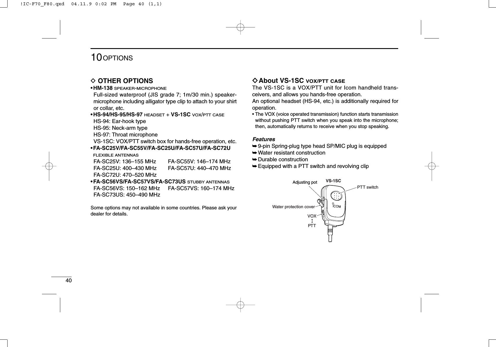
![4110OPTIONS10VOX gain and delay adjustmentqAttach the connector of the VS-1SC into the [SP/MIC] con-nector on the transceiver and tighten the screw.• Toggle the toggle switch to [VOX].wEnter user set mode. (p. 17)ePush [P0] several times to select the “VOX Gain” or “VOXDelay” items. Then, push [Up] or [Down] to set the desiredlevel/condition.rRotate [VOL] to turn the power OFF to exit set mode.• VOX GainThe VOX sensitivity level can be adjusted from OFF or 1 to 6.• VOX DelayThe VOX delay time can be set from 0.5 to 3.0 sec. (0.5 sec.step) for a convenient interval before returning to receive.NOTE: MIC/VOX gain can be adjusted via the Adjustingpot using a thin screw driver.0.5 sec (min.)XTXCSET3.0 sec (max.)XTXCSET[Up]Push[Down]VOX function is OFFXTXCSETVOX gain level 3XTXCSET[Up]Push[Down]!IC-F70_F80.qxd 04.11.9 0:02 PM Page 41 (1,1)](https://usermanual.wiki/ICOM-orporated/280402/User-Guide-500789-Page-45.png)