ICOM orporated 281600 VHF Transceiver User Manual Updated
ICOM Incorporated VHF Transceiver Updated
UserManual.wiki
>
ICOM orporated
>
281600 User Manual
>
Updated User Manual
Contents
1.
RF Training Manual Info
2.
Users Manual
3.
Updated User Manual
Updated User Manual
Navigation menu
Upload a User Manual
Namespaces
Wiki Guide
HTML
PDF
Info
Views
User Manual
Discussion / Help
Navigation
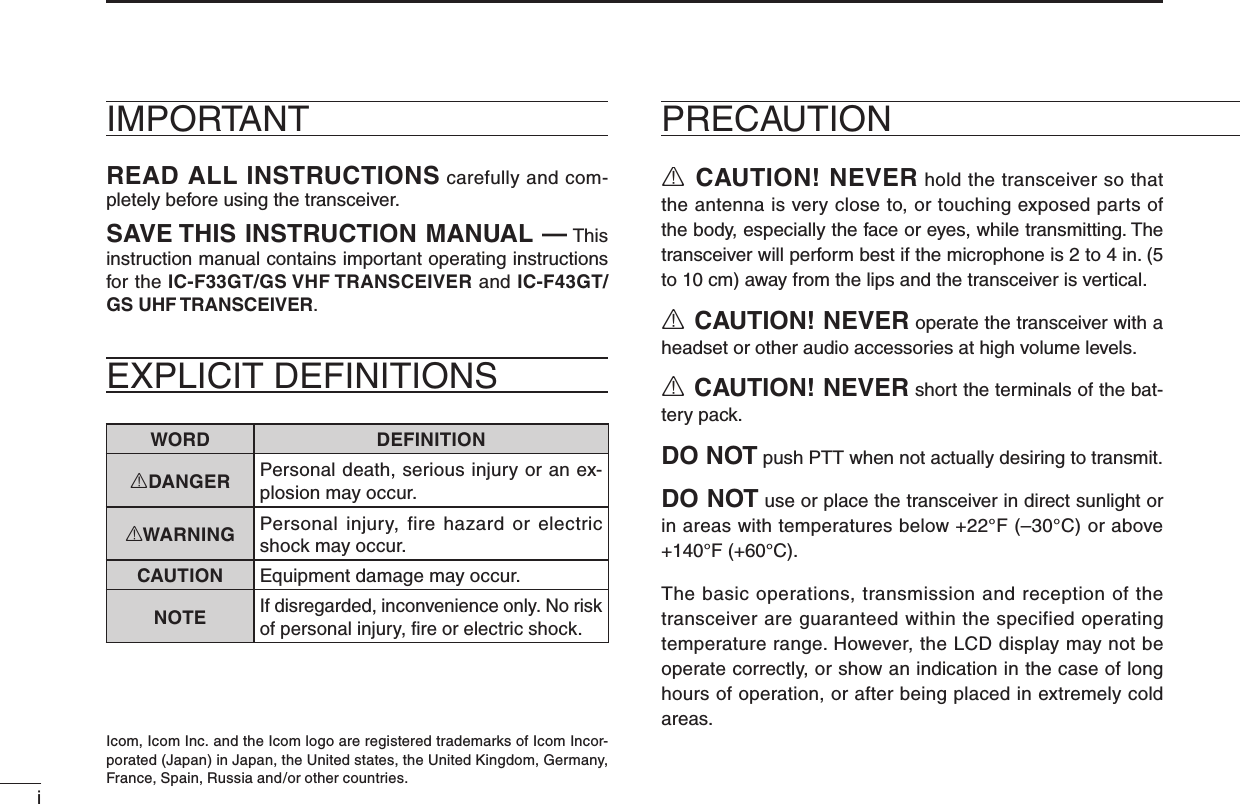
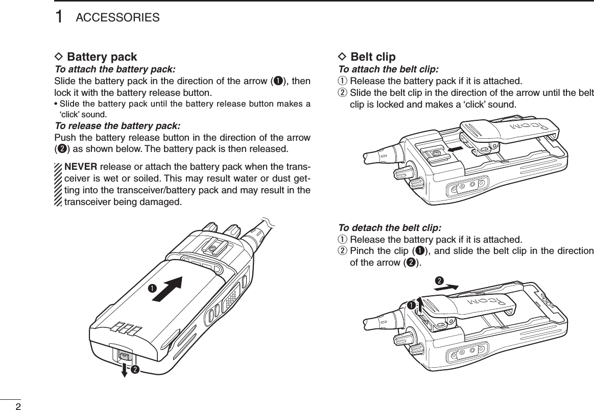
![31ACCESSORIESD Jack cover Attach the jack cover when the optional speaker-microphone is not used.To attach the jack cover:q Attach the jack cover on the [SP]/[MIC] jack.w Tighten the screws.To detach the jack cover:q Unscrew the screws with a Phillips screwdriver.w Detach the jack cover for the speaker-microphone connection.qwqw](https://usermanual.wiki/ICOM-orporated/281600.Updated-User-Manual/User-Guide-1870911-Page-7.png)
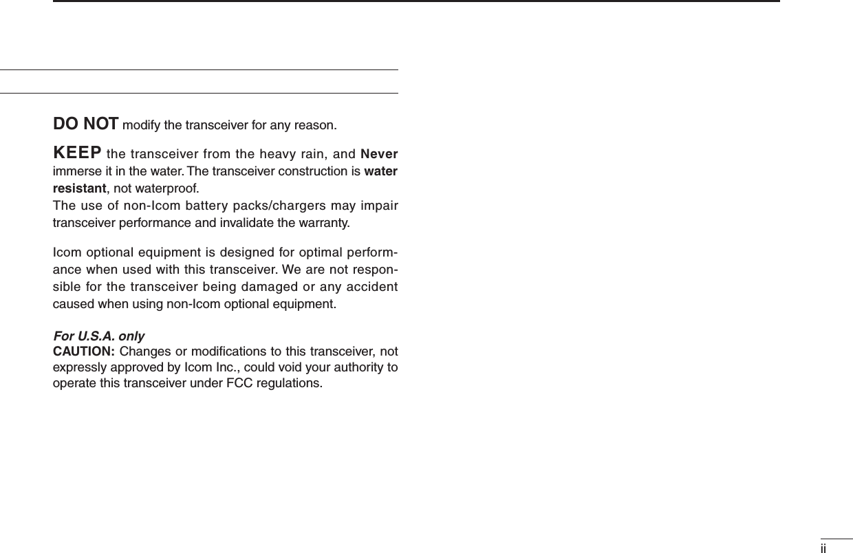
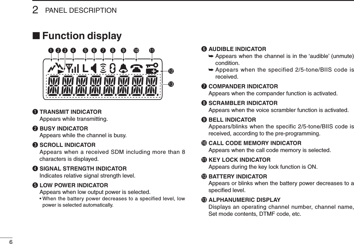
![42PANEL DESCRIPTION■ Front panelq ROTARY SELECTORRotate to select the pre-programmed memory channels or the operating bank. (Depending on the pre-setting)w VOLUME CONTROL [VOL]Rotate to turn the power ON/OFF and adjusts the audio level.e DEALER-PROGRAMMABLE KEY [RED]Desired function can be programmed by your dealer. (p. 7)r [SP]/[MIC] JACKConnect the optional speaker-microphone.t FUNCTION DISPLAYDisplays a variety of information such as an operating channel number/name, 2/5-tone code, DTMF numbers, selected function, etc.y DEALER-PROGRAMMABLE KEYS [P0] to [P3]Desired functions can be programmed independently by your dealer. (p. 7)[SP]/[MIC] jack coverNOTE: Attach the [SP]/[MIC] jack cover when the optional speaker-microphone is not used. (See p. 3 for details)itrqeuywo!0!110-keypad version](https://usermanual.wiki/ICOM-orporated/281600.Updated-User-Manual/User-Guide-1870911-Page-8.png)
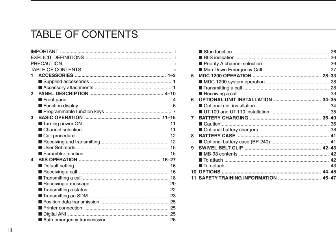
![52PANEL DESCRIPTIONu 10-KEYPAD (Depending on version)The keypad allows you to enter digits to: • Select memory channels • Select tone channels • Select DTMF codes (during transmit) • Set TX codes • Set BIIS status number • Input text message for SDM operation • Start up with the passwordi UP/DOWN KEYS➥ Push to select an operating channel.➥ Push to select a TX code channel after pushing [TX CODE CH SELECT].➥ Push to select a DTMF channel after pushing [DTMF].➥ Push to select a scan group after pushing and holding [SCAN].➥ Push to select a BIIS code, status number or SDM after pushing [DIGITAL]. * Desired functions can be programmed independently by your dealer. (p. 7)o PTT SWITCH [PTT]➥ Push and hold to transmit; release to receive.➥ Push to transmit the call during MSK operation, depending on the setting.!0 MONITOR KEY ➥Mute and release the CTCSS (DTCS) or 2-tone squelch mute. Open any squelch/deactivate any mute while pushing this key. (LMR operation only) ➥ Activates one of (or two of) the following functions on each channel independently. (PMR or BIIS PMR operation only) • Push and hold the key to unmute the channel (audio is emitted; ‘audible’ condition). • Push the key to toggle the mute and unmute conditions (toggles ‘audible’ and ‘inaudible’). • Push the key to mute the channel (sets to ‘inaudible’ only). • Push the key to unmute the channel (sets to ‘audible’ only). • Push the key after communication is nished to send a ‘reset code.’ • Push the key after communication is nished to send a ‘clear down code’ during BIIS operation on an MSK channel. NOTE: The unmute condition (‘audible’ conditions) may automatically return to the mute condition (‘inaudible’ condition) after a specified period. * Desired function can be programmed by your dealer. (p. 7)!1 ANTENNA CONNECTORConnects the supplied antenna.](https://usermanual.wiki/ICOM-orporated/281600.Updated-User-Manual/User-Guide-1870911-Page-9.png)
![72PANEL DESCRIPTION■ Programmable function keysThe following functions can be assigned to [UP], [DOWN], [P0], [P1], [P2], [P3], [RED] and [MONITOR] programmable function keys. Consult your Icom dealer or system operator for details con-cerning your transceivers programming.If the programmable function names are bracketed in the fol-lowing explanations, the specific key is used to activate the function depends on the programming.CH UP AND DOWN KEYS➥ Push to select an operating channel.➥ Push to select a transmit code channel after pushing [TX Code CH Select].➥ Push to select a DTMF channel after pushing [DTMF Autodial].➥ Push to select a scan group after pushing and holding [Scan A Start/Stop]/[Scan B Start/Stop].➥ Push to select a BIIS code, status number or SDM after pushing [Digital].➥ Push to select the MDC menu after pushing [MDC CALL].➥ Push to select the desired transceiver alias or message channel while in the transceiver alias or message channel selection mode.BANK SELECT KEYPush this key, then push [CH Up] or [CH Down] to select the desired bank.SCAN A KEY➥ This key’s operation depends on the Power ON Scan set-ting. When the power ON scan function is turned OFF; Push to start and cancel scanning operation. In case of transmission during scan, cancels scanning. When the power ON scan function is turned ON; Push to pause scanning. Scanning resumes after pass-ing a specified time period. In case of transmission during scan, pauses scanning. Scanning resumes after passing a specified time period specified. ➥ Push and hold this key for 1 sec. to indicate the scan group, then push [CH Up] or [CH Down] to select the desired group.SCAN B KEY➥ Push to start and cancel scanning operation. In case of transmission during scan, pauses scanning. Scanning resumes after passing a specified time period. ➥ Push and hold this key for 1 sec. to indicate the scan group, then push [CH Up] or [CH Down] to select the desired group.SCAN TAG KEYPush to add or delete the selected channel to the scan group.PRIORITY CHANNEL KEYS➥ Push to select Priority A or Priority B channel.➥ Push and hold [Prio A (Rewrite)] to rewrite the Prio A channel.](https://usermanual.wiki/ICOM-orporated/281600.Updated-User-Manual/User-Guide-1870911-Page-11.png)
![82PANEL DESCRIPTIONMR-CH 1/2/3/4 KEYSPush to select an operating channel directly.MONITOR KEY ➥ Mute and release the CTCSS (DTCS) or 2-tone squelch mute. Open any squelch/deactivate any mute while push-ing this key. (LMR operation only)➥ Activates one of (or two of) the following functions on each channel independently: (PMR or BIIS PMR opera-tion only) • Push and hold to un-mute the channel (audio is emitted; ‘Audible’ condition). • Push to mute the channel (sets to ‘Inaudible’ only). • Push to un-mute the channel (sets to ‘Audible’ only). • Push after the communication is nished to send a ‘reset code’. NOTE: The un-mute condition (‘Audible’ condition) may automatically return to the mute condition (‘Inaudible‘ condition) after a specified period.LOCK KEYPush and hold to electronically lock all programmable keys except the following:[Call] (incl. Call A and Call B), [Moni(Audi)] and [Emergency].OUTPUT POWER SELECTION KEYPush to select the transmit output power temporarily or per-manently, depending on the pre-setting.• Ask your dealer for the output power level for each selection.C.TONE CHANNEL ENTER KEYPush to select the continuous tone channel using [CH Up]/[CH Down] to change the tone frequency/code set-ting after pushing this key for permanent operation.TALK AROUND KEYTurn the talk around function ON and OFF.• The talk around function equalizes the transmit frequency to the receive frequency for transceiver-to-transceiver communication.WIDE/NARROW KEYPush to toggle the IF bandwidth between wide and narrow.• The wide passband width can be selected from 25.0 or 20.0 kHz using the CS-F33G c l o n i n g s o f t w a r e . (PMR or BIIS PMR opera-tion only) Ask your Dealer for details.DTMF AUTODIAL KEY➥ Push to enter the DTMF channel selection mode. Then select the desired DTMF channel using [CH Up]/[CH Down] keys.➥ After selecting the desired DTMF channel, push this key to transmit the DTMF code.DTMF RE-DIAL KEYPush to transmit the last-transmitted DTMF code.CALL KEYSPush to transmit a 2/5-tone/BIIS ID code.• Call transmission is necessary before you call another station depending on your signalling system.• [Call A] and/or [Call B] may be available when your system employs selective ‘Individual/Group’ calls. Ask your dealer which call is assigned to each key.](https://usermanual.wiki/ICOM-orporated/281600.Updated-User-Manual/User-Guide-1870911-Page-12.png)
![92PANEL DESCRIPTIONEMERGENCY KEYS➥ Push and hold to transmit an emergency call. ➥ When [Emergency Single (Silent)] or [Emergency Repeat (Silent)] is pushed, an emergency call is transmitted with-out a beep emission and LCD indication change. • If you want to cancel the emergency call, push (or push and hold) the key again before transmitting the call. • The emergency call is transmitted one time only or repeatedly until receiving a control code depending on the pre-setting.TX CODE ENTER KEY (PMR or BIIS PMR operation only)Push to enter the direct ID code edit mode, for both 5-tone and MSK. Then set the desired digit using [CH Up]/[CH Down]/[TX Code CH Up]/[TX Code CH Down] or 10-key-pad.* (p. 14)*Depending on versionTX CODE CHANNEL SELECT KEY➥ Push to enter the direct ID code channel selection mode. Then set the desired channel using [CH Up]/[CH Down]/[TX Code CH Up] or [TX Code CH Down]. (p. 13)➥ While in ID code channel selection mode, push for 1 sec. to enter the ID code edit mode for 5-tone and MSK. Then set the desired digit using [CH Up]/[CH Down]/[TX Code CH Up]/[TX Code CH Down] or 10-keypad.* (p. 14) *Depending on versionTX CODE CHANNEL UP/DOWN KEYSPush to select a TX code channel directly.ID MEMORY READ KEY (PMR or BIIS PMR operation only)➥ Recalls detected ID codes. • Push this key, then push [CH Up]/[CH Down] for selection. • Up to 5 ID’s are memorized.➥ Push and hold to erase the selected memorized ID’s.VOICE SCRAMBLER FUNCTIONPush to toggle the voice scrambler function ON and OFF.COMPANDER KEYPush to toggle the compander function ON and OFF. The compander function reduces noise components from the transmitting audio to provide clear communication.USER SET MODE KEY➥ Push and hold to enter user set mode. • During user set mode, push this key to select an item, and push [CH Up]/[CH Down] to change the value or condition.➥ Push and hold this key again to exit user set mode.OPT OUT KEYSPush to control the optional unit connector output signal level.DIGITAL KEY (BIIS operation only)➥ Push to select the call ID list, transmit message and standby condition. Toggles between queue channel and received message record indication after queue channel is selected.➥ Push and hold to select queue channel indication.](https://usermanual.wiki/ICOM-orporated/281600.Updated-User-Manual/User-Guide-1870911-Page-13.png)
![102PANEL DESCRIPTIONSTATUS UP/DOWN KEYS (BIIS operation only)➥ While in the standby condition, push to display the trans-mit status indication and select a status number.➥ When a received SDM is displayed, push to cancel the automatic scroll and scroll the message manually.➥ When an SDM that contains more than 8 characters is displayed, push to scroll the message manually.MDC CALL KEY (MDC operation only)➥ Push to enter the MDC menu selection mode. Then select the desired MDC menu from “SELCALL,” “MSG,” “STATUS,” “RADIOCHK” and “CALALERT” using [CH Up]/[CH Down]/[MDC Up]/[MDC Down]. After selection, push this key again to enter the transceiv-er alias or message channel selection mode.➥ While in the transceiver alias or message channel selec-tion mode, push to return to the MDC menu selection mode.MDC UP AND DOWN KEYS (MDC operation only)➥ Push to select the MDC menu after pushing [MDC CALL].➥ Push to select the desired transceiver alias or message channel while in the transceiver alias or message channel selection mode.MDC SELCALL KEY (MDC operation only)Push to enter the transceiver alias selection mode.• After the desired alias selection, push [PTT] to transmit a selective call.MDC CALLALERT KEY (MDC operation only)Push to enter the transceiver alias selection mode.• After the desired alias selection, push [PTT] to transmit a call alert.MDC EMG KEY (MDC operation only)Push and hold for a speified period to transmit an MDC emergency call.• If you want to cancel the emergency call, push (or push and hold) the key again before transmitting the call.](https://usermanual.wiki/ICOM-orporated/281600.Updated-User-Manual/User-Guide-1870911-Page-14.png)
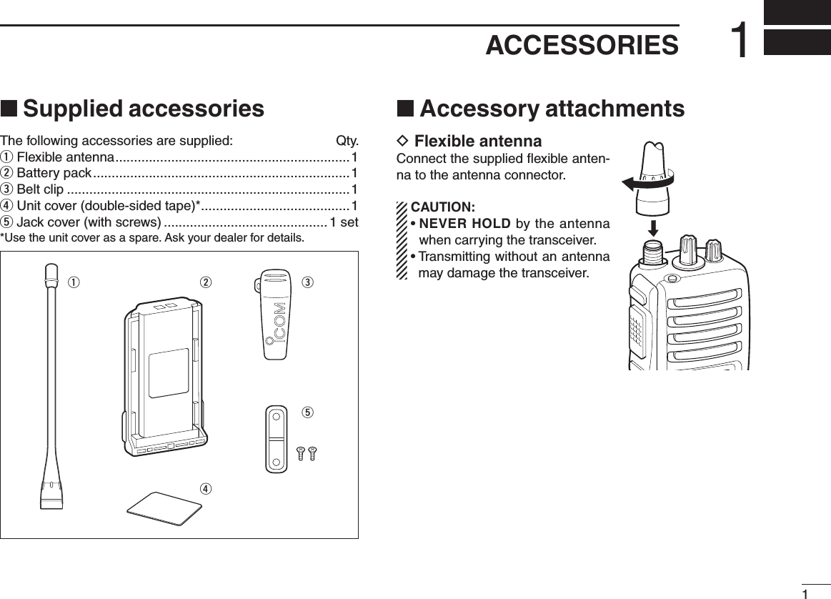
![113BASIC OPERATION■ Turning power ONq Rotate [VOL] to turn the power ON.w If the transceiver is programmed for a start up password, input the digit codes as directed by your dealer. • 10-keypad can be used for password input depending on ver-sion: • The keys in the table below can be used for password input: • The transceiver detects numbers in the same block as identical. Therefore “01234” and “56789” are the same.e When the “PASSWORD” indication does not clear after inputting 4 digits, the input code number may be incorrect. Turn the power off and start over in this case.■ Channel selectionSeveral types of channel selections are available. Methods may differ according to your system set up.NON-BANK TYPE:Push [UP] or [DOWN], or rotate [ROTARY SELECTOR]* to select the desired operating channel, in sequence; or, push one of [MR-CH 1] to [MR-CH 4] keys to select a channel directly.• Up to 16 pre-programmed channels can be selected via [ROTARY SELECTOR].*BANK TYPE:Push [BANK], then push [UP] or [DOWN] or rotate [ROTARY SELECTOR]* to select the desired bank.AUTOMATIC SCAN TYPE:Channel setting is not necessary for this type. When turning power ON, the transceiver automatically starts scanning. Scanning stops when receiving a call.*Depending on the pre-setting.KEYNUMBER 0549382716DOWN](https://usermanual.wiki/ICOM-orporated/281600.Updated-User-Manual/User-Guide-1870911-Page-15.png)
![123BASIC OPERATION■ Call procedureWhen your system employs tone signaling (excluding CTCSS and DTCS), the call procedure may be necessary prior to voice transmission. The tone signalling employed may be a selec-tive calling system which allows you to call specific station(s) only and prevent unwanted stations from contacting you.q Select the desired TX code channel or 2/5-tone code according to your System Operator’s instructions. • This may not be necessary depending on programming. • Refer to pgs. 13 or 14 for selection.w Push the call key (assigned to one of the dealer pro-grammable keys: [Up], [Down], [P0], [P1], [P2], [P3], [Emergency] and [Monitor]) or [PTT].e After transmitting a 2/5-tone code, the remainder of your communication can be carried out in the normal fashion.■ Receiving and transmitting NOTE: Transmitting without an antenna may damage the transceiver. See p. 1 for antenna attachment.Receiving:q Rotate [VOL] to turn the power ON.w Push [UP] or [DOWN], or rotate [ROTARY SELECTOR]* to select a channel, in sequence. *Depending on the pre-setting.e When receiving a call, adjust the audio output level to a comfortable listening level.Transmitting:Wait for the channel to become clear to avoid interference.q While pushing and holding [PTT], speak into the micro-phone at a normal voice level.w Release [PTT] to return to receive. IMPORTANT: To maximize the readability of your signal; 1. Pause briefly after pushing [PTT]. 2. Hold the microphone 5 to 10 cm (2 to 4 inches) from your mouth, then speak into the microphone at a nor-mal voice level.Selective calling Non-selective calling](https://usermanual.wiki/ICOM-orporated/281600.Updated-User-Manual/User-Guide-1870911-Page-16.png)
![133BASIC OPERATIOND Transmitting notes• Transmit inhibit functionThe transceiver has several inhibit functions which restrict transmission under the following conditions:- The channel is in mute condition (‘Inaudible’ condition; “” does not appear.)- The channel is busy.- Un-matched (or matched) CTCSS is received. (Depending on the pre-setting.)- The selected channel is a ‘receive only’ channel.• Time-out timerAfter continuous transmission for the pre-programmed time period, the time-out timer is activated, causing the transceiv-er to stop transmitting.• Penalty timerOnce the time-out timer is activated, transmission is further inhibited for a period determined by the penalty timer.D TX code channel selectionIf the transceiver has [TX Code CH Select] assigned to it, indication can be toggled between the operating channel number (or name) and TX code channel number (or name). When the TX code channel number (or name) is displayed, [UP]/[DOWN] selects the TX code channel.TO SELECT A TX CHANNEL:q Push [TX Code CH Select]— a TX code channel appears.w Push [UP] or [DOWN] to select the desired TX code chan-nel.e Push [Call] (or [PTT] during MSK operation) to transmit the selected TX code.r Push [TX Code CH Select] again to return to the operat-ing channel number indication.FOR TX CODE CHANNEL TYPE:If the transceiver has a [TX Code CH Up] or [TX Code CH Down] key assignment, the programmed TX code channel can be selected directly.](https://usermanual.wiki/ICOM-orporated/281600.Updated-User-Manual/User-Guide-1870911-Page-17.png)
![143BASIC OPERATIOND TX code number edit (PMR or BIIS PMR operation only)If the transceiver has [TX Code CH Select] or [TX Code Enter] assigned to it, TX code contents can be edited within the allowable digits.TO EDIT A TX CODE VIA [TX CODE CH SELECT] KEY:q Push [TX Code CH Select] to enter the TX code channel selection mode. • Select the desired channel using [UP] or [DOWN] if necessary.w Push [TX Code CH Select] for 1 sec. to enter the TX code edit mode.e Push [TX Code CH Select] to select the desired digit to be edited.r Set the desired digit using [UP], [DOWN], [TX Code CH Up], [TX Code CH Down] or 10-keypad.* *Depending on version.t Push [TX Code CH Select] to set the digit. The editable digit will move to the right automatically. • When the 10-keypad is used to set, the editable digit will move to the right automatically without pushing [TX Code CH Select].y Repeat r and t to input all allowable digits.u Push [Call] or [PTT] to transmit the edited TX code.TO EDIT A TX CODE VIA [TX CODE ENTER] KEY:q Select the desired TX code channel via [TX Code CH Up] or [TX Code CH Down].w Push [TX Code Enter] to enter the TX code edit mode.e Push [TX Code Enter] to select the desired digit to be edited.r Set the desired digit using [UP], [DOWN], [TX Code CH Up] or [TX Code CH Down] or 10-keypad*. *Depending on version.t Push [TX Code Enter] to set the digit. The editable digit will move to the right automatically. • When the 10-keypad is used to set, the editable digit will move to the right automatically without pushing [TX Code CH Select].y Repeat r and t to input all allowable digits.u Push [Call] or [PTT] to transmit the edited TX code.](https://usermanual.wiki/ICOM-orporated/281600.Updated-User-Manual/User-Guide-1870911-Page-18.png)
![153BASIC OPERATIOND DTMF transmissionIf the transceiver has [DTMF Autodial] assigned to it, the automatic DTMF transmission function is available. Up to 8 DTMF channels are available.TO SELECT A TX CODE:q Push [DTMF Autodial]— a DTMF channel appears.w Push [UP] or [DOWN] to select the desired DTMF chan-nel.e Push [DTMF Autodial] to transmit the DTMF code in the selected DTMF channel.■ User set modeUser set mode is accessed with [User Set Mode] and allows you to set seldom-changed settings. In this case you can “customize” the transceiver operation to suit your prefer-ences and operating style.Entering the user set mode:q Push and hold [User Set Mode] to enter user set mode. Push [User Set Mode] momentarily to select the item. Then push [UP] or [DOWN] to set the desired level/condi-tion. • Available set mode functions are Backlight, Beep, SQL Level, Mic Gain and Battery Voltage.w Push and hold [User Set Mode] to exit user set mode.■ Scrambler functionThe voice scrambler function provides private communi-cation between stations. The frequency inversion type is equipped to all versions, moreover, the optional Rolling or Non-rolling type can be available.q Push [Scrambler] to turn the scrambler function ON. • “ ” appears.w Push [Scrambler] again to turn the scrambler function OFF. • “ ” disappears.](https://usermanual.wiki/ICOM-orporated/281600.Updated-User-Manual/User-Guide-1870911-Page-19.png)
![164BIIS OPERATION■ Default settingThe following functions are assigned to each programmable key as the default. However, the assigned function can be changed by your dealer. Ask your dealer for details. NOTE: [TX Code Enter] must be assigned to any key.[P0]; Call : Push to transmit a 5-tone/BIIS call when the selected channel is a 5-tone or MSK channel, respec-tively.[P1]; Digital : Push to select the call list ID/trans-mit message, or to display the receive message record for selec-tion.[P3]; TX Code Enter : Push to enter the direct ID code edit mode for both 5-tone and MSK.[UP]/[DOWN]; CH Up/Down : While in the standby condition, selects the operating channel. After pushing [Digital] or [TX Code CH Select], selects call list or TX code channel, respectively.[MONITOR]; Moni(Audi): Push this key after the communica-tion to send a ‘Clear down’ signal during MSK channel operation.[P2]/[RED]; Null : No function is assigned.■ Receiving a callD Individual callq When an individual call is received; • Beeps sound. • “ ” appears and the mute is released. • The programmed text message (e.g.“ ”) and the call-ing station ID (or text) is displayed alternately, depending on the setting. • “ ” appears or blinks depending on the setting.w Push and hold [PTT], then speak into the microphone at a normal voice level. • “ ” indicator appears.e Release [PTT] to return to receive. • “ ” appears while receiving a signal.r To finish the conversation, push [MONITOR] (Moni(Audi)) to send the ‘Clear down’ signal. • Either station can send a ‘Clear down’ signal. • “ ” is displayed for 2 sec. (approx.). • “ ” disappears and the transceiver returns to the standby con-dition.Appears or blinksAppears](https://usermanual.wiki/ICOM-orporated/281600.Updated-User-Manual/User-Guide-1870911-Page-20.png)
![174BIIS OPERATIOND Group callq When a group call is received; • Beeps sound. • “ ” appears and the mute is released. • The programmed text message (e.g.“ ”) and the calling station ID (or text) is displayed alternately, depending on the setting. • “ ” appears or blinks depending on the setting.w Push and hold [PTT], then speak into the microphone at a normal voice level. NOTE: Only one station is permitted to speak. • “ ” appears.e Release [PTT] to return to receive. • “ ” appears while receiving a signal.r To finish the conversation, push [MONITOR] (Moni(Audi)) to send the ‘Clear down’ signal. • Either station can send a ‘Clear down’ signal. • “ ” is displayed for 2 sec. (approx.) • “ ” disappears and the transceiver returns to the standby con-dition.D Displaying the received call record — Queue indicationThe transceiver memorizes the calling station IDs for record. Up to 3 calls can be memorized, and the oldest call record is erased when a 4th call is received. However, once the trans-ceiver is powered OFF, the all records are cleared.q Push [P1] (Digital) for 1 sec. • Displays following indication. When a record is available When no record is availablew Push [UP] or [DOWN] to select the desired call.e Push [P1] (Digital) for 1 sec. again to return to the stand-by condition. • When no operation is performed for 30 sec., the transceiver returns to the standby condition automatically.Appears or blinksAppears](https://usermanual.wiki/ICOM-orporated/281600.Updated-User-Manual/User-Guide-1870911-Page-21.png)
![184BIIS OPERATION■ Transmitting a callTotal of a 3 ways for code selection are available—selecting the call code from memory, entering the call code from the keypad and calling back from the queue channel record.D Using call memoryq While in the standby condition, push [P1] (Digital) to enter the call code memory channel selection mode. • “ ” appears.w Push [UP] or [DOWN] to select the desired call code.e Push [P0] (Call) or [PTT]* to call. * PTT call can be made only when PTT call capability is permitted. NOTE: When no answer back is received, the trans-ceiver repeats the call 3 times (default) automatically, and “ ” is displayed during each call. However, an error beep sounds and “ ” is displayed when no answer back is received after the calls.r Push [PTT] to transmit; release to receive.t Push [MONITOR] (Moni(Audi)) to send the ‘Clear down’ signal.D Calling back from the queue channelq While in the standby condition, push [P1] (Digital) for 1 sec. to enter the queue memory channel selection mode.w Push [UP] or [DOWN] to select the desired record.e Push [P0] (Call) or [PTT]* to call. *PTT call can be made only when PTT call capability is permitted. NOTE: When no answer back is received, the trans-ceiver repeats the call 3 times (default) automatically, and “ ” is displayed during each call. However, an error beep sounds and “ ” is displayed when no answer back is received after the calls.r Push [PTT] to transmit; release to receive.t Push [MONITOR] (Moni(Audi)) to send the ‘Clear down’ signal.Call code text is displayed.Appears](https://usermanual.wiki/ICOM-orporated/281600.Updated-User-Manual/User-Guide-1870911-Page-22.png)
![194BIIS OPERATIOND Direct code entryq While in the standby condition, push [P3] (TX Code Enter) to enter the TX code edit mode. • Editable code digit blinks.w Push [P3] (TX Code Enter) to select the desired digit to be edited. • Editable digit differs according to the setting.e Set the desired digit using [CH Up]/[CH Down]/[TX Code CH Up]/[TX Code CH Down] or 10-keypad.* *Depending on versionr Push [P3] (TX Code Enter) to set the digit, then the edit-able digit will move to the right automatically. • When the 10-keypad is used to set, the editable digit will move to the right automatically without pushing [P3] (TX Code Enter).t Repeat e and r to input all allowable digits.y Push [P0] (Call) or [PTT]* to call. * PTT call can be made only when PTT call capability is permitted. NOTE: When no answer back is received, the trans-ceiver repeats the call 3 times (default) automatically, and “ ” is displayed during each call. However, an error beep sounds and “ ” is displayed when no answer back is received after the calls.u Push [PTT] to transmit; release to receive.i Push [MONITOR] (Moni(Audi)) to send the ‘Clear down’ signal.For your information When the “UpDate” setting for the call code is enabled, the set code is overwritten into the call code memory.](https://usermanual.wiki/ICOM-orporated/281600.Updated-User-Manual/User-Guide-1870911-Page-23.png)
![204BIIS OPERATION■ Receiving a messageD Receiving a status messageq When a status message is received; • Beeps sound. • The calling station ID (or text) and the status message is dis-played alternately, depending on the setting.w Push [MONITOR] (Moni(Audi)) to return to the standby condition. NOTE: Only the calling station ID (or text) is displayed (no message is displayed alternately) when the scroll timer is set to ‘OFF.’ In this case, push [Status Up]/[Status Down] to display the status message manually.D Receiving an SDMq When an SDM is received; • Beeps sound. • The calling station ID (or text) and the SDM is displayed alter-nately, depending on the setting.w When the received SDM includes more than 8 characters, “” appears and the message scrolls automatically, when the automatic scroll function is activated. • Push [Status Up]/[Status Down] to scroll the message manually.e Push [MONITOR] (Moni(Audi)) to return to the standby condition.](https://usermanual.wiki/ICOM-orporated/281600.Updated-User-Manual/User-Guide-1870911-Page-24.png)
![214BIIS OPERATIOND Received message selectionThe transceiver memorizes the received messages for record. Up to 6 messages for status and SDM, or 95 charac-ter SDM’s can be memorized. The oldest message is erased when the 7th message is received. However, once the trans-ceiver is powered OFF, all messages are cleared.q Push [P1] (Digital) for 1 sec. • Displays queue memory.w Push [P1] (Digital) momentarily. • Displays message memory. When a message is available When no message is availablee Push [UP] or [DOWN] to select the desired message. • When selecting the SDM that includes more than 8 characters, “” appears and the message scrolls automatically, when the automatic scroll function is activated. • Push [Status Up]/[Status Down] to scroll the message manually.r Push [P1] (Digital) for 1 sec. again to return to the stand-by condition. • When no operation is performed for 30 sec., the transceiver returns to the standby condition automatically.](https://usermanual.wiki/ICOM-orporated/281600.Updated-User-Manual/User-Guide-1870911-Page-25.png)
![224BIIS OPERATION■ Transmitting a statusD GeneralThe status message can be selected with the programmed text, and the message text is also displayed on the function display of the called station.Up to 24 status types (1 to 24) are available, and the status messages 22 and 24 have designated meanings.Status 22: Emergency*Status 24: GPS request* The status 22 can also be used as a normal status message by disabling the designated meaning. However, the status 24 is fixed.The status call can be sent with both individual and group calls.D Transmitting a statusq While in the standby condition, push [P1] (Digital), then push [UP] or [DOWN] to select the desired station/group code.w Push [P1] (Digital) again, then push [UP] or [DOWN] to select the desired status message. Or, you can select the desired status message using [Status Up]/[Status Down] key directly.e Push [P0] (Call) or [PTT]* to transmit the status message to the selected station/group. *PTT call can be made only when PTT call capability is permitted. • 2 beeps will sound and the transceiver returns to the standby condition automatically when the transmission is successful.Status message is displayed.](https://usermanual.wiki/ICOM-orporated/281600.Updated-User-Manual/User-Guide-1870911-Page-26.png)
![234BIIS OPERATION■ Transmitting an SDMD GeneralThe short data message, SDM, can be sent to an individual station or group stations. Also, 8 SDM memory channels are available and the messages can be edited via PC program-ming.D Transmitting an SDMq While in the standby condition, push [P1] (Digital), then push [UP] or [DOWN] to select the desired station/group code.w Push [P1] (Digital) again, then push [UP] or [DOWN] to select the desired SDM. Or, you can select the desired SDM using [Status Up]/[Status Down] key directly.e Push [P0] (Call) or [PTT]* to transmit the SDM to the selected station/group. *PTT call can be made only when PTT call capability is permitted. • 2 beeps will sound and the transceiver returns to the standby condition automatically when the transmission is successful.SDM is displayed.](https://usermanual.wiki/ICOM-orporated/281600.Updated-User-Manual/User-Guide-1870911-Page-27.png)
![244BIIS OPERATIOND Programming an SDM memory (10-keypad version is required)q During standby condition, push [P1] (Digital) twice, then push [UP] or [DOWN] to select the desired SDM to be edited.w Push [M] or [#] to enter the message editing condition. • The rst character blinks when [#] is pushed, the last character blinks when [M] is pushed as below.e Push the appropriate digit key, [0] to [9], to enter the desired character. • See the table at right for the available characters. • Pushing [UP] also enters space, pushing [DOWN] deletes the selected character.r Push [#] to move the cursor to the right, push [M] to move the cursor to the left.t Repeat steps e and r to set the desired text message.y Push [P1] (Digital) for 1 sec. to overwrite the set content into the memory. • Push [P1] (Digital) momentarily to cancel the editing and return to the original message indication. • Available characters NOTE: Once the pre-programmed character including a decimal point is rewrote with the 10-keypad, the decimal point cannot be displayed again.Key[0][1][2][3][4][5][6][7][8][9]Characters(0)(1)(2)(3)(4)(5)(6)(7)(8)(9)(.)(Space)(A)(D)(G)(J)(M)(P)(T)(W)(!)(#)(B)(E)(H)(K)(N)(Q)(U)(X)(?)(�)(C)(F)(I)(L)(O)(R)(V)(Y)(')(/)(a)(d)(g)(j)(m)(S)(t)(Z)(")(+)(b)(e)(h)(k)(n)(p)(u)(w)(,)(Ð)(c)(f)(i)(l)(o)(q)(v)(x)(;)(=)(r)(y)(:)(_) (() ()) (<) (>) ([) (])(/)(&) (%) ($) (@) (^)(s)(z)](https://usermanual.wiki/ICOM-orporated/281600.Updated-User-Manual/User-Guide-1870911-Page-28.png)
![264BIIS OPERATION■ Auto emergency transmissionWhen [Emergency Single (Silent)] or [Emergency Repeat (Silent)] is pushed, an emergency signal is automatically transmitted for the specified time period.The status 22 (Emergency) is sent to the selected ID station, and the position data is transmitted after the emergency sig-nal when a GPS receiver is connected to the transceiver.The emergency transmission is performed on the emer-gency channel, however, when no emergency channel is specified, the signal is transmitted on the previously selected channel.There is no change in the function display or beep emission during automatic emergency transmission.■ Stun functionWhen the specified ID, set as a killer ID, is received, the stun function is activated.When the killer ID is received, the transceiver switches to the password required condition. Entering of the password via the keypad is necessary to operate the transceiver again in this case.■ BIIS indicationThe following indications are available for the BIIS operation on an MSK channel.: Individual/group call is successful.: Message (status or SDM) transmission is suc-cessful.: No answer back is received.: Appears during retry of the call (2nd call).: End the communication.: Operating channel is in the busy condition.■ Priority A channel selectionWhen one of the following operations is performed, the transceiver selects the Priority A channel automatically.Priority A is selected when;• Clear down signal is received/transmitted - Set the ‘Move to PrioA CH’ item as ‘Clear down.’• Turning the power ON The Priority A channel is selected each time the trans-ceiver power is turned ON.• Status call The Priority A channel is selected when transmitting a status call. - Enable the ‘Send Status on PrioA CH’ item in the MSK configuration.](https://usermanual.wiki/ICOM-orporated/281600.Updated-User-Manual/User-Guide-1870911-Page-30.png)
![285MDC 1200 OPERATION■ MDC 1200 system operationThe MDC 1200 signaling system enhances your transceiver’s capabilities. It allows PTT ID*, Selective Calling, Call Alert, Radio Check, Messaging and Emergency signaling. Also, the dispatcher can stun and revive transceivers on the sys-tem.An additional feature of MDC 1200 found in Icom transceiv-ers is called aliasing. Each transceiver on the system has a unique ID number. Aliasing allows the substitution of an alphanumeric name for this ID number. For transmit, you can use this alias to select a transceiver to call. For receive, the alias of the calling station is displayed instead of the ID.The following section describes the operation of the MDC 1200 features using the alias function. The Selective Call, Call Alert and Radio Check features can also be used with direct ID code entry from the transceiver keypad. (p. 32)Please note that your dealer has set one of the programma-ble keys (P0, P1, P2, or P3) for MDC 1200 operation.*When [PTT] is pushed or released, self ID is transmitted.■ Transmitting a callD Transmitting a Selective CallSelective calling allows you to make a call to a specific sta-tion or to a particular group. Other MDC 1200 transceivers on the channel will not receive a selective call that does not match their station or group ID’s.q Push [MDC Call] to enter the MDC menu selection mode. • Or push [MDC Selcall] to enter the transceiver alias selection mode. In this case, skip step w.w Push [MDC Call] again to enter the transceiver alias selection mode.e Select the desired alias using [CH Up], [CH Down], [MDC Up] or [MDC Down].r Push and hold [PTT] to transmit the selective call to the selected station, then speak into the microphone.t Release [PTT] to receive.SELL CALL is displayed.](https://usermanual.wiki/ICOM-orporated/281600.Updated-User-Manual/User-Guide-1870911-Page-32.png)
![295MDC 1200 OPERATIOND Transmitting a Call AlertCall Alert allows you to notify another user who may be away from the transceiver that you want to talk.q Push [MDC Call] to enter the MDC menu selection mode. • Or push [MDC CallAlert] to enter the transceiver alias selection mode. In this case, skip steps w and e.w Select “CALALERT” using [CH Up], [CH Down], [MDC Up] or [MDC Down].e Push [MDC Call] again to enter the transceiver alias selection mode.r Select the desired alias using [CH Up], [CH Down], [MDC Up] or [MDC Down].t Push [PTT] to transmit the call alert to the selected sta-tion. • “CA CALL” is displayed.y Release [PTT]. • “CA OK” is displayed if the targeted station received the alert. • “CA FAIL” is displayed if the targeted station does not send an acknowledgement.u After a specified time period has passed, the transceiver will return to receive.D Transmitting a Radio Check CallRadio check call allows you to determine whether another transceiver is turned on, within range and on channel with-out requiring any action from the targeted station user.q Push [MDC Call] to enter the MDC menu selection mode.w Select “RADIOCHK” using [CH Up], [CH Down], [MDC Up] or [MDC Down].e Push [MDC Call] again to enter the transceiver alias selection mode.r Select the desired alias using [CH Up], [CH Down], [MDC Up] or [MDC Down].t Push [PTT] to transmit the radio check call to the selected station. • “RDO CHK” is displayed.y Release [PTT]. • “CHK ACK” is displayed if the targeted station is turned ON, on channel and within range. • “CHK FAIL” is displayed if the targeted station does not send an acknowledgement.u After a specified time period has passed, the transceiver will return to receive.](https://usermanual.wiki/ICOM-orporated/281600.Updated-User-Manual/User-Guide-1870911-Page-33.png)
![305MDC 1200 OPERATIOND Transmitting a Status MessageStatus Messaging allows you to send a pre-programmed status message to the dispatcher. There are 16 status codes that can be sent. In addition, the dispatcher can send an MDC 1200 signal that causes the transceiver to automati-cally transmit its current status.q Push [MDC Call] to enter the MDC menu selection mode.w Select “STATUS” using [CH Up], [CH Down], [MDC Up] or [MDC Down].e Push [MDC Call] again to enter the status message selec-tion mode.r Select the desired status message using [CH Up], [CH Down], [MDC Up] or [MDC Down].t Push [PTT] to transmit the status message to the dis-patcher. • “STAT TX” is displayed.y Release [PTT]. • “STAT OK” is displayed. • “STA FAIL” is displayed if there is no acknowledgment from the dispatcher.u After a specified time period has passed, the transceiver will return to receive.Pre-programmed status message is displayed.](https://usermanual.wiki/ICOM-orporated/281600.Updated-User-Manual/User-Guide-1870911-Page-34.png)
![315MDC 1200 OPERATIOND Transmitting a MessageThe transceiver can send a pre-programmed message to the dispatcher. There are 16 messages that can be sent on a channel.q Push [MDC Call] to enter the MDC menu selection mode.w Select “MSG” using [CH Up], [CH Down], [MDC Up] or [MDC Down].e Push [MDC Call] again to enter the pre-programmed mes-sage selection mode.r Select the desired message using [CH Up], [CH Down], [MDC Up] or [MDC Down].t Push [PTT] to transmit the message to the dispatcher. • “MSG TX” is displayed.y Release [PTT]. • “MSG OK” is displayed. • “MSG FAIL” is displayed if there is no acknowledgment from the dispatcher.u After a specified time period has passed, the transceiver will return to receive.D Emergency CallsThe MDC 1200 Emergency feature can be accessed using the [MDC Emg] key (p. 10). The optional UT-124 man d o w n unit can also activate this feature. The transceiver will repeatedly send an Emergency MDC 1200 command to the dispatcher for a programmed length of time until it receives an acknowledgement signal. The emergency call can be transmitted without a beep emis-sion and LCD indication change depends on the setting.With MDC 1200 Emergency, the transceiver can also be programmed to keep the microphone open during an emer-gency call, allowing monitoring of the situation.Ask your dealer for details.D Stun and ReviveThe dispatcher can send MDC 1200 signals that will stun or revive your transceiver. If a Stun command is received that matches your station ID, the transceiver will display “SORRY” and you can not receive or transmit. When a Revive com-mand is received that matches your station ID, normal oper-ation is restored.Pre-programmed message is displayed.](https://usermanual.wiki/ICOM-orporated/281600.Updated-User-Manual/User-Guide-1870911-Page-35.png)
![325MDC 1200 OPERATIOND Programming station ID code (10-keypad version is required)If your transceiver is equipped with a 10-keypad, you can enter a station ID code from the keypad for the Selective Call, Call Alert or Radio Check Call functions.q Push [MDC Call] to enter the MDC menu selection mode.w Select “SELCALL”, “RADIOCHK” or “CALALERT” using [CH Up], [CH Down], [MDC Up] or [MDC Down].e Push [MDC Call] again to enter the transceiver alias selection mode.r Push any key of the keypad to enter the ID code program-ming condition. • The rst digit blinks as below.t Push [UP] to move the cursor to the right, push [DOWN] to move the cursor to the left.y When the last digit of the desired ID has been entered, push [PTT] to transmit. • Available charactersKey CharactersKey[0][1][2][3][4][5]Characters(0)(1)(2)(3)(4)(5)(6)(7)(8)(9)(A)(D)(B)(E)(C)(F)[6][7][8][9][M][#] (3) (D) (E) (F)(A)](https://usermanual.wiki/ICOM-orporated/281600.Updated-User-Manual/User-Guide-1870911-Page-36.png)
![335MDC 1200 OPERATION■ Receiving a callD Receiving a Selective Callq When an individual call is received; • Beeps sound. • “ ” blinks. • The calling station ID (or alias) and “SELCALL” are displayed alternately.w Push and hold [PTT] and speak into the microphone.e Release [PTT] to receive a response.D Receiving a Call Alertq When a Call Alert is received; • Beeps sound. • “ ” blinks. • The calling station ID (or alias) and “CALLALRT” are displayed alternately.w Push and hold [PTT] and speak into the microphone.e Release [PTT] to receive a response.BlinksBlinks](https://usermanual.wiki/ICOM-orporated/281600.Updated-User-Manual/User-Guide-1870911-Page-37.png)
![346OPTIONAL UNIT INSTALLATION■ Optional unit installationInstall the optional unit as follows:q Rotate [VOL] to turn the power OFF, and remove the bat-tery pack. (p. 2)w Remove the unit cover. NOTE: Use a flat head screw driver or a similar flat instrument, and insert into the hollow of the chassis, then lift and take away the unit cover. Use the supplied spare unit cover! Do not use the cover that has been removed once. Water or dust may get into the trans-ceiver because the cover may be bent or has lost it’s adhesion. This may result in the transceiver being damaged.e Install the unit as shown below.r Replace the unit cover and the battery pack, then rotate [VOL] to turn the power ON. NOTE: The optional UT-109/UT-110 scrambler units require some PC board modifications. Please refer to the additional installation as shown on p. 35.*This illustration is described with the UT-109.](https://usermanual.wiki/ICOM-orporated/281600.Updated-User-Manual/User-Guide-1870911-Page-38.png)
![356OPTIONAL UNIT INSTALLATION■ UT-109 and UT-110 installationThe following PC board modification is required when install-ing the optional UT-109 or UT-110:q Rotate [VOL] to turn the power OFF, and remove the bat-tery pack. (p. 2)w Remove the unit cover as shown on p. 34 (Optional unit installation).e Cut the pattern on the PCB at the TX mic circuit (C) and RX AF circuit (F) as shown below.r Install the scrambler unit as described in the Optional unit installation (p. 34).t Replace the unit cover and the battery pack, then rotate [VOL] to turn the power ON. NOTE: When uninstalling the scrambler unit Be sure to re-solder the disconnected points at left, other-wise no TX modulation or AF output is available.](https://usermanual.wiki/ICOM-orporated/281600.Updated-User-Manual/User-Guide-1870911-Page-39.png)