ICOM orporated 282600 VHF Scanning Receiver User Manual IC V82 11
ICOM Incorporated VHF Scanning Receiver IC V82 11
UserManual.wiki
>
ICOM orporated
>
282600 User Manual
>
Users Manual Part 1
Contents
1.
Users Manual Part 1
2.
Users Manual Part 2
Users Manual Part 1
Navigation menu
Upload a User Manual
Namespaces
Wiki Guide
HTML
PDF
Info
Views
User Manual
Discussion / Help
Navigation
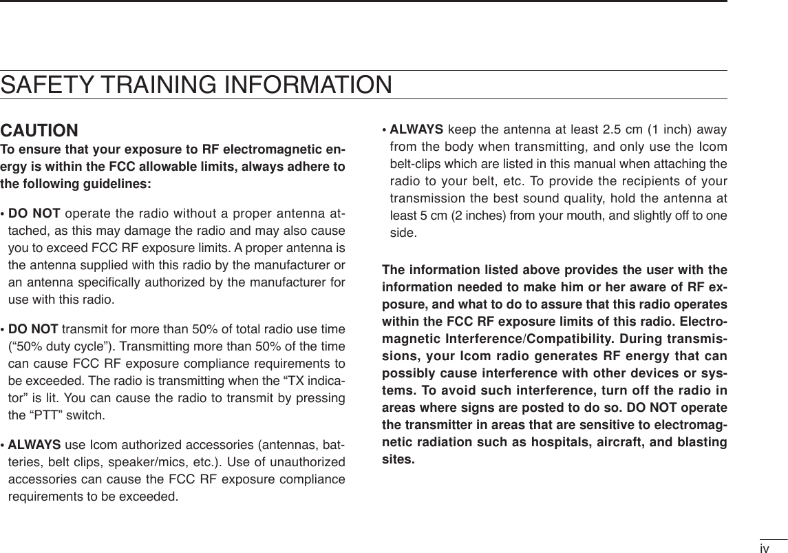
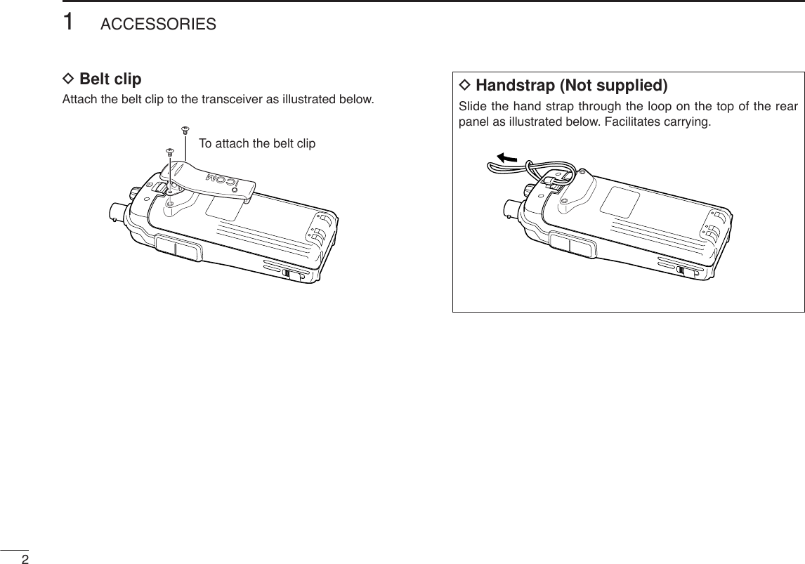
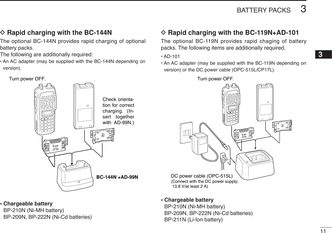
![IQUICK REFERENCE GUIDE■PreparationDBattery pack replacementBefore replacing the battery pack, push [PWR] for 1 sec. toturn the power OFF.•Slide the battery release forward, then pull the battery pack upwardwith the transceiver facing away from you.DBattery case— optional for some versionsWhen using a BP-208N BATTERY CASEattached to the trans-ceiver, install 6 AA (LR6) size alkaline batteries as illustratedbelow.DCharging with the BC-144N/146The optional BC-144N provides rapid charging, and the BC-146 provides regular charging of an optional battery packwith/without transceiver. The following is additionally required:• An optional AC adapter. (An AD-99N is supplied with BC-144N orBC-146.)Check orientation for correct charg-ing. (Insert together with AD-99N.)Turn power OFF.BC-144N/146 +AD-99N](https://usermanual.wiki/ICOM-orporated/282600.Users-Manual-Part-1/User-Guide-486359-Page-8.png)
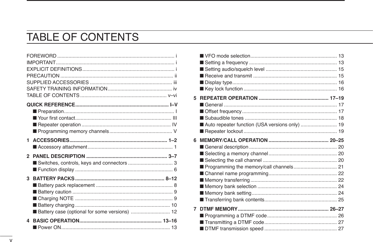
![IIIQUICK REFERENCE GUIDE■Your first contactNow that you have your IC-V82 ready, you are exited to geton the air. We would like to walk you through a few basic op-erational steps to make your first “On The Air” use an enjoy-able experience.DAbout default settingThe [VOL] control function can be traded with [YY]/[ZZ]keys func-tion in INITIAL SET MODE. However, in this QUICK REFERENCE,the factory default setting ([VOL] controls audio output level) isused for simple instructions.DBasic operation1. Turning ON the transceiverAlthough you have purchased a brand new transceiver, somesettings may be changed from the factory defaults becauseof the QC process. Resetting the CPU is necessary to startfrom factory default.➥While pushing [MONI] and[D•CLR], push [PWR] for 1 sec. toreset the CPU and turn power ON.2. Adjusting sudio output level➥Rotate [VOL] to set the desiredaudio level.3. Adjusting the squelch level➥While pushing and holding[MONI], push [YY]or [ZZ]to set thesquelch level.4. Tune the desired frequencyThe up/down keys, [YY]/[ZZ], willallow you to tune the frequency thatyou want to operate on. Page 14 willinstruct you on how to adjust the tun-ing step.➥Push [YY]or [ZZ]to adjust the fre-quency.PWRMONICLRDMONI[VOL]](https://usermanual.wiki/ICOM-orporated/282600.Users-Manual-Part-1/User-Guide-486359-Page-10.png)
![IVQUICK REFERENCE GUIDEDirect frequency input from the key-pad is also available. ➥To enter the desired frequency,enter 6-digits starting from the100 MHz digit.•Enter three* to five digits then push-ing [✱•ENT]is also set the fre-quency. (*Some versions areavailable from two digits.)•When a digit is mistakenly input,push [D.CLR]to abort to input.5. Transmit and receive ➥Push and hold [PTT] to transmit, then speak into the mi-crophone; release to receive.■Repeater operation1. Setting duplex➥Push [A•FUNC], then [4•DUP]sev-eral times to select minus duplexor plus duplex.•The USA version has an auto re-peater function, therefore, setting du-plex is not required.2. Repeater tone➥Push [A•FUNC], then [1•TONE]several times until “ ” appears, ifrequired.TONE1FUNCADUP4FUNCA• Example 1— when entering 145.525 MHzPush• Example 2— when entering 144.800 MHzP.BEEP2DUP4DUPTONE41SCAN5SCAN5SCAN5PushDUPTONE41OPT0SET8ENTCLRDKeypadENTQuick reference guide](https://usermanual.wiki/ICOM-orporated/282600.Users-Manual-Part-1/User-Guide-486359-Page-11.png)
![VQUICK REFERENCE GUIDEThe IC-V82 has a total of 207 memory channels (including 6scan edges and 1 call channel) for storing often used operat-ing frequency, repeater settings, etc.1. Setting frequencyIn VFO mode, set the desired operating frequency with otherdesired settings, such as repeater and subaudible tone.2. Selecting a memory channel➥Push [A•FUNC], [C•MR]then push[YY] or [ZZ]several times to selectthe desired memory channel.•“X” indicator and memory channelnumber blink.3. Writing a memory channel➥Push [A•FUNC], then push [C•MR]for 1 sec. to program.•3 beeps sound•Continue to hold [C•MR]down for 1 sec. after 3 beeps are emit-ted, to increment the displayed memory channel number.MRCFUNCAMRCFUNCA■Programming memory channels](https://usermanual.wiki/ICOM-orporated/282600.Users-Manual-Part-1/User-Guide-486359-Page-12.png)
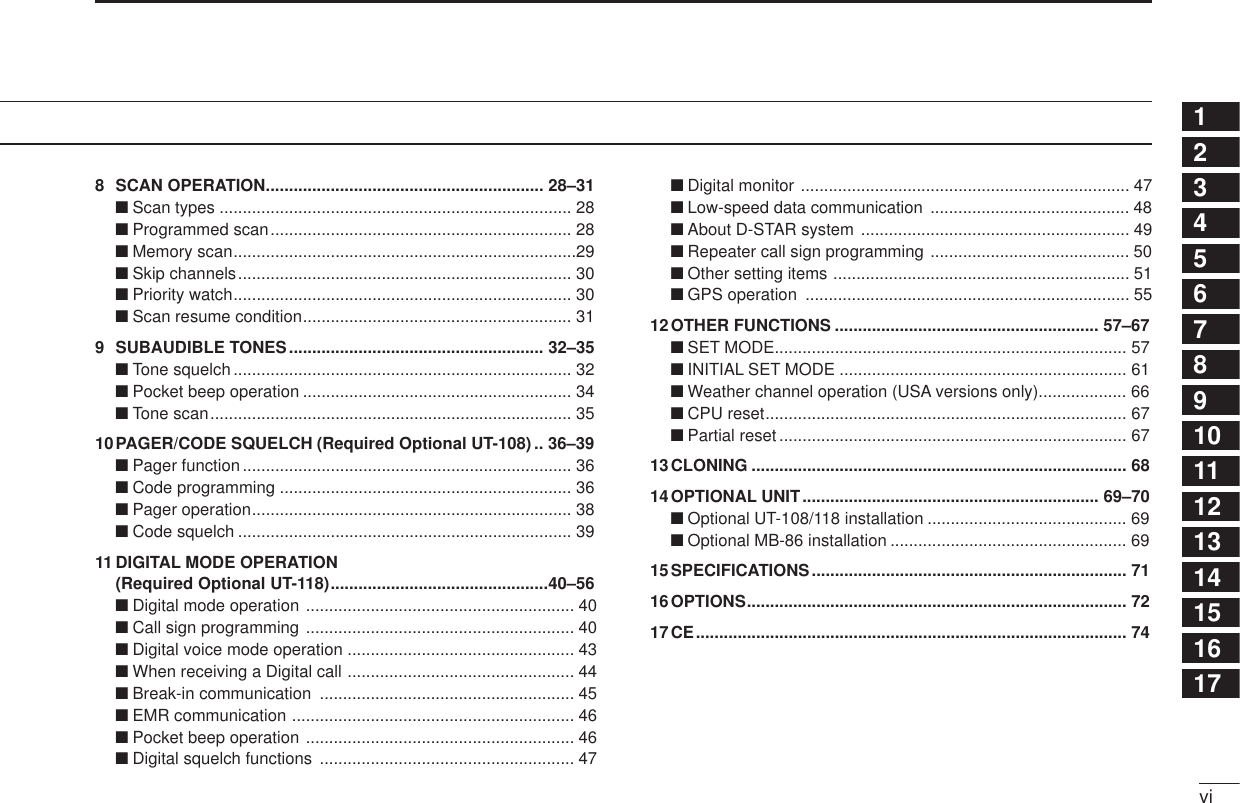
![11ACCESSORIES1■Accessory attachmentDAntennaAttach the antenna to the transceiver as illustrated below. Keep the [SP/MIC] cap (SP/MIC jack cover) attached whenjacks are not in use to avoid bad contacts.Attach the[SP/MIC] cap.[SP/MIC] cap](https://usermanual.wiki/ICOM-orporated/282600.Users-Manual-Part-1/User-Guide-486359-Page-13.png)
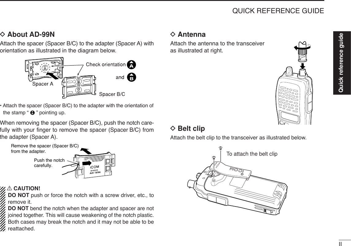
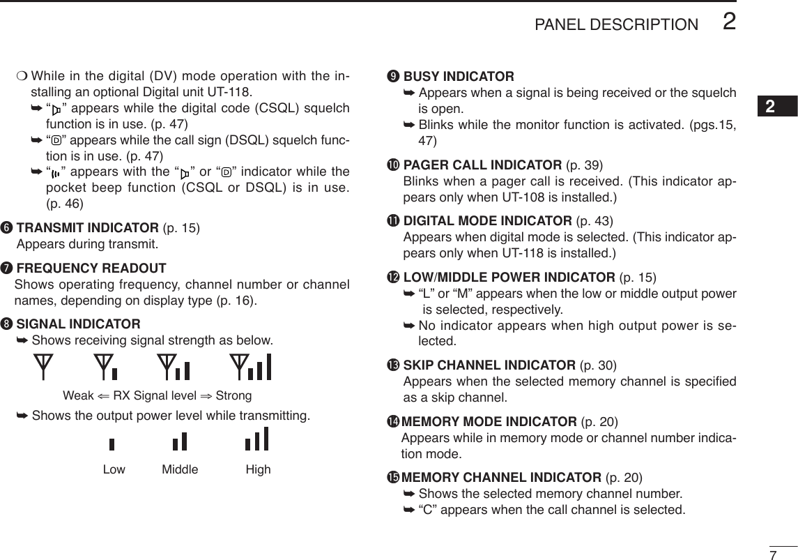
![32PANEL DESCRIPTION12qCONTROL DIAL [VOL]*Rotate to adjust the volume level.wPTT SWITCH [PTT]Push and hold to transmit; release to receive.eUP/DOWN KEYS [YY]/[ZZ]*Selects the operating frequency.rKEY PAD (pgs. 4, 5) Used to enter operating frequency, the DTMF codes, etc.tANTENNA CONNECTORConnects the supplied antenna.y[SP]/[MIC] JACKConnect an optional speaker-microphone or headset, if de-sired. The internal microphone and speaker will not func-tion when either is connected.uFUNCTION DISPLAY (pgs 6, 7)iSQUELCH/MONITOR SWITCH [MONI]Push and hold to force the squelch open and set the trans-ceiver to the squelch level adjustable condition.oPOWER SWITCH [PWR]Push for 1 sec. to turn the power ON and OFF.MONICALLDUP SCANPRIOENTSETH/M/LOPTSKIPBANKTONET.SCANP.BEEPMR CLRFUNCPWR9874123AB DC560qwtMicrophoneSpeakery!0ouier■Switches, controls, keys and connectors*The assigned function for [VOL] and [YY]/[ZZ]can betraded in INITIAL SET MODE(pgs. 14, 63).](https://usermanual.wiki/ICOM-orporated/282600.Users-Manual-Part-1/User-Guide-486359-Page-15.png)
![42PANEL DESCRIPTION!0 [DATA] JACKConnect to a PC or GPS receiver via the RS232C cable (D-sub 9 pin) for data communication in the RS-232C format.DKey pad[A•FUNC]Access to secondary function.[B•CALL]Select the call channel. (p. 20)[C•MR]➥Selects a memory mode. (p. 20)➥After pushing [A•FUNC], entering into memoryprogramming/editing mode. (pgs. 21–23)➥After pushing [A•FUNC], programs/transfersVFO/memory or call channel contents intomemory channel/VFO when pushed for 1 sec.(pgs. 21–23)[D•CLR]Selects VFO mode, aborts direct frequency input,or cancels scanning, etc. (pgs. 13, 28)[1•TONE]➥Input digit “1” during frequency input, memorychannel selection, etc. (pgs. 13, 20)➥After pushing [A•FUNC], selects the subaudibletone function. (pgs. 17, 32)[2•P.BEEP]➥Input digit “2” during frequency input, memorychannel selection, etc. (pgs. 13, 20)➥After pushing [A•FUNC], turn the pocket beepfunction ON and OFF. (p. 34)P.BEEP2TONE1CLRDMRCCALLBFUNCAPin 2 (RxD), Pin 3 (TxD), Pin 5 (GND)to [DATA] jackTxD2.5(d) mm Less than10(d) mmGNDRxD1569RS-232C(DB-9 female)Make sure the connection between transceiver and PC, oth-erwise misreading may occur for data communication.](https://usermanual.wiki/ICOM-orporated/282600.Users-Manual-Part-1/User-Guide-486359-Page-16.png)
![52PANEL DESCRIPTION2[3•T.SCAN]➥Input digit “3” during frequency input, memorychannel selection, etc. (pgs. 13, 20)➥After pushing [A•FUNC], starts the tone scan-ning. (pgs. 18, 35)[4•DUP]➥Input digit “4” during frequency input, memorychannel selection, etc. (pgs. 13, 20)➥After pushing [A•FUNC], selects a duplex func-tion (–duplex, +duplex, simplex). (p. 17)[5•SCAN]➥Input digit “5” during frequency input, memorychannel selection, etc. (pgs. 13, 20)➥After pushing [A•FUNC], starts scanning. (p. 28)[6•SKIP]➥Input digit “6” during frequency input, memorychannel selection, etc. (pgs. 13, 20)➥After pushing [A•FUNC], sets and cancels skipsetting for memory skip scan during memorymode. (p. 30)[7•PRIO]➥Input digit “7” during frequency input, memorychannel selection, etc. (pgs. 13, 20)➥After pushing [A•FUNC], starts the prioritywatch. (p. 30)[8•SET]➥Input digit “8” during frequency input, memorychannel selection, etc. (pgs. 13, 20)➥After pushing [A•FUNC], enters into SET MODE.(p. 57)[9•H/M/L]➥Input digit “9” during frequency input, memorychannel selection, etc. (pgs. 13, 20)➥After pushing [A•FUNC], switches transmitpower from high, middle and low output power.(p. 15)[0•OPT]➥Input digit “0” during frequency input, memorychannel selection, etc. (pgs. 13, 20)➥After pushing [A•FUNC], selects an optionalfunction mode, such as pager, code squelch ordigital operation. (pgs. 38, 40)[#•BANK]After pushing [A•FUNC], enters a memory bankcondition. (p. 24)[✱•ENT]➥Sets the frequency even if the full 6-digits offrequency have not been entered. (p. 13)➥After pushing [A•FUNC], switches key lock func-tion ON and OFF when pushed for 1 sec. Lockall keys, except [PWR], [PTT], [MONI] andaudio level adjustment. (p. 16)ENTBANKOPT0H/M/L9SET8PRIO7SKIP6SCAN5DUP4T.SCAN3](https://usermanual.wiki/ICOM-orporated/282600.Users-Manual-Part-1/User-Guide-486359-Page-17.png)

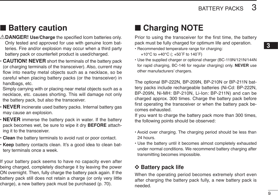
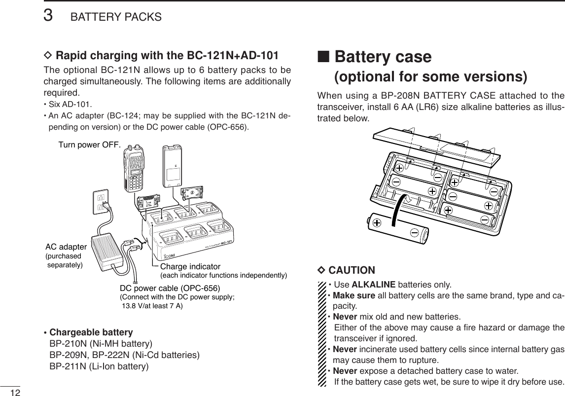
![■Battery pack replacement➥Before replacing the batterypack, push [PWR] for 1 sec.to turn the power OFF.➥Slide the battery release forward, then pull the battery packupward with the transceiver facing away from you.DDBATTERY PACKS*1Operating periods are calculated under the following conditions;Tx : Rx : standby =1 : 1 : 8, power save function: auto setting isactivated*2Operating period depends on the alkaline cells used. Battery Voltage Capacity Battery life*1packBP-208N Battery case for AA —*2(LR6)×6 alkalineBP-209N 7.2 V 1100 mAh 3 hrs. 20 min.BP-210N 7.2 V 1650 mAh 6 hrs.BP-211N 7.4 V 1800 mAh 6 hrs. 10 min.BP-222N 7.2 V 600 mAh 2 hrs. 15 min.Push for 1 sec.PWR8BATTERY PACKS3](https://usermanual.wiki/ICOM-orporated/282600.Users-Manual-Part-1/User-Guide-486359-Page-20.png)
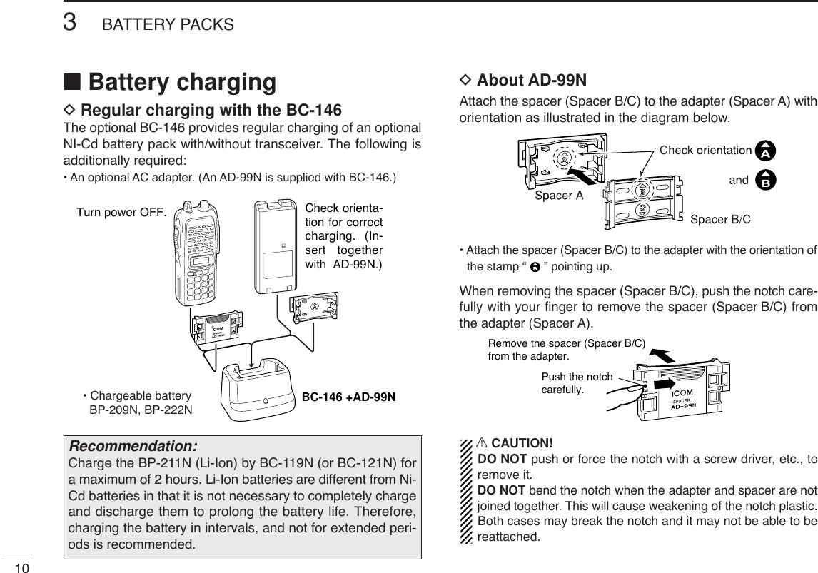
![134BASIC OPERATION34■Power ON➥Push [PWR] for 1 sec. to turnpower ON.■VFO mode selectionThe transceiver has 2 basic oper-ating modes: VFO mode andmemory mode.➥Push [D•CLR]to select VFOmode.■Setting a frequencyDVia the keypadqPush [D•CLR]to select VFO mode, if necessary.wTo enter the desired frequency, enter 6-digits starting fromthe 100 MHz digit.•Enter three* to five digits then pushing [✱•ENT]is also set thefrequency. (*Some versions are available from two digits.)•When a digit is mistakenly input, push [D.CLR]to abort to input.• Example 1— when entering 145.525 MHzPush• Example 2— when entering 144.800 MHzP.BEEP2DUP4DUPTONE41SCAN5SCAN5SCAN5PushDUPTONE41OPT0SET8ENTCLRDPush for 1 sec.PWR](https://usermanual.wiki/ICOM-orporated/282600.Users-Manual-Part-1/User-Guide-486359-Page-25.png)
![DBy other methodsVia the [YY]/[ZZ] keys➥Push [YY]or [ZZ]several times to set the desired frequency.•Each push increases/decreases the frequency by the selectedtuning step. See right content for tuning step details.DTuning step selectionThe IC-V82 has 8 tuning steps— 5,10, 12.5, 15, 20, 25, 30 and 50 kHz.The tuning step is selectable in SETMODE. qPush [A•FUNC]then [8•SET]toenter SET MODE.wPush [YY]or [ZZ]several times toselect the tuning step item.eRotate [VOL] to select the desired tuning step.rPush [✱•ENT]to exit SET MODE.[VOL]ENTFUNCASET8144BASIC OPERATION✔For your information— [VOL] function assignmentThe [VOL] control can be used asa tuning dial for frequency tuning in-stead of [YY]/[ZZ]keys. However,while [VOL] functions as tuningdial, [YY]/[ZZ]keys functions as AFvolume control.qWhile pushing [YY]and [ZZ], turnpower ON to enter INITIAL SETMODE. wPush [YY]or [ZZ]several times toselect the dial assignment item, “tOP.”eRotate [VOL] to select the condition.rTo exit SET MODE, push [✱•ENT].[VOL] is assigned as AF volume control. [VOL] is assigned as tuning dial.[VOL]ENTPWR](https://usermanual.wiki/ICOM-orporated/282600.Users-Manual-Part-1/User-Guide-486359-Page-26.png)
![154BASIC OPERATION4■Setting audio/squelch levelDTo set the audio levelRotate [VOL] to set the desiredaudio level while receiving a sig-nal.• When no signal is received, pushand hold [MONI] while setting theaudio level. • When [VOL] is assigned as tuningdial, push [YY]/[ZZ]to adjust the audiooutput level. (pgs. 14, 63)DTo set the squelch levelWhile pushing [MONI], push[YY]/[ZZ]to set the squelch level.• The squelch level “1” is loosesquelch, “10” is tight squelch.• When [VOL] is assigned as tuningdial, rotate [VOL] while [MONI] ispushed. (pgs. 14, 63)■Receive and transmitqPush [PWR] for 1 sec. to turn the power ON.wAdjust audio volume to the desired level.eSet a frequency.When a signal is received:• Squelch opens and audio is emitted from the speaker.• Signal indicator shows the relative signal strength level.rPush [A•FUNC], then [9•H/M/L]to select output power be-tween high, middle and low.•“L” appears when low power is selected.•“M” appears when middle power is selected.•No indication appears when high power is selected.tPush and hold [PTT] to transmit, then speak into the micro-phone.• “$” appears.•Do not hold the microphone too close to your mouth orspeak too loudly. This may distort the signal.yRelease [PTT] to receive. ✔For your information— Monitor function:Push and hold [MONI] to listen to weak signals that do notopen the squelch.MONI[VOL]](https://usermanual.wiki/ICOM-orporated/282600.Users-Manual-Part-1/User-Guide-486359-Page-27.png)
![164BASIC OPERATION■Display type The transceiver has 3 display types to suit your operatingstyle.The display type is selected in INITIAL SET MODE(p. 63).“Frequency Indication” typeDisplays operating frequency.“Channel Number Indication” typeDisplays memory channel number. In this type only pre-programmed memory channel numbers are displayed. VFO mode cannot be selected.• When the channel indication type is selected, only the followingfunctions can be performed.- Scan function (p. 28)- Output power setting (p. 15)- DTMF memory function (p. 26)- Key lock function (see right content)- Scan pause timer setting, function key timer setting and LCDbacklight setting in SET MODE(p. 59)“Channel Name Indication” typeDisplays memory channel name you have assigned. In thisdisplay pre-programmed memory channel names are dis-played. VFO mode is selectable.• Programmed frequencies are indicated pre-programmed in theselected memory channel.• Push and hold [MONI] to display the operating frequency.■Key lock functionThe key lock function prevents accidental frequency changesand function activation.Push [A•FUNC]then push [✱•ENT]for 1 sec. to toggle the function ON andOFF.•“ ” appears while the lock function isactivated.•[PWR], [PTT], [VOL] and [MONI] canbe operated regardless of this setting.USINGINITIAL SET MODEFUNCAENT](https://usermanual.wiki/ICOM-orporated/282600.Users-Manual-Part-1/User-Guide-486359-Page-28.png)
![175REPEATER OPERATION45■GeneralWhen using a repeater, the transmit frequency is shifted fromthe receive frequency by the offset frequency. It is convenientto program repeater information into memory channels.qSet the receive frequency (repeater output frequency).wPush [A•FUNC]and [4•DUP]several times to select “–” or“+.”•“–” indicates the transmit frequency is shifted down; “+” indicatesthe transmit frequency is shifted up.• Blinking “–” or “+” indicates the reversed duplex mode is selectedin SET MODE(p. 58).ePush [A•FUNC]and [1•TONE]several times to activate thesubaudible tone encoder, if required.•“ ” appears.•Select the desired subaudible tone frequency, if necessary. (p. 18)rPush and hold [PTT] to transmit.•The displayed frequency automatically changes to the transmitfrequency (repeater input frequency).•If “OFF” appears, check the offset frequency (see right contentfor details) and direction.tRelease [PTT] to receive.yPush and hold [MONI] to check whether the other station’stransmit signal can be directly received or not.About reversed duplex modeWhen the reversed duplex mode is selected, the receivefrequency shifts. (Transmit frequency shifts in normal du-plex mode.)Each receive and transmit frequency is shown in the tablebelow with the following conditions;Inputed freq.: 145.30 MHzDirection : – (negative) Offset frequency : 0.6 MHz■Offset frequencyWhen communicating through a repeater, the transmit fre-quency is shifted from the receive frequency by an amountdetermined by the offset frequency.qPush [A•FUNC], then push [8•SET]to enter SET MODE.wPush [YY]or [ZZ]several times until “±” and offset frequencyappear.eRotate [VOL] to select the desired offset frequency.•Selectable steps are the same as the pre-set tuning steps.•The unit of the displayed offset frequency is “MHz.”rPush [✱•ENT](or [D•CLR]) to fix the offset frequency andexit SET MODE.USINGSET MODEReversed OFF ON Rx freq. 145.30 MHz 144.70 MHzTx freq. 144.70 MHz 145.30 MHz](https://usermanual.wiki/ICOM-orporated/282600.Users-Manual-Part-1/User-Guide-486359-Page-29.png)
![■Subaudible tonesSome repeaters require subaudible tones to be accessed.Subaudible tones are superimposed over your normal signaland must be set in advance.qPush [A•FUNC], then push [8•SET]to enter SET MODE.wPush [YY]or [ZZ]one or more times until “rt” appears.eRotate [VOL] to select the desired subaudible tone.rPush [✱•ENT](or [D•CLR]) to fix the selected tone andexit SET MODE.• Available subaudible tone frequencies (unit: Hz)DDTone informationSome repeaters require another tone system to be accessed. DTMF TONESWhile pushing [PTT], push the desired DTMF keys (0–9,[A•FUNC], [B•CALL], [C•MR], [D•CLR], [#•BANK]and[✱•ENT]) to transmit DTMF tones.•[✱•ENT]enters as “E”, [#•BANK]enters as “F.”•The transceiver has 16 DTMF memory channels (p. 26).1750 Hz TONEWhile pushing [PTT], push [YY]or [ZZ]to transmit a 1750 Hztone signal.✔ConvenientTone scan function: When you don’t know the subaudibletone used for a repeater, the tone scan is convenient for de-tecting the tone frequency.Push [A•FUNC], then push [3•T.SCAN]to start the tone scan.• Push [D•CLR]to cancel the scan.• When the required tone frequency is detected, the scanpauses.67.069.371.974.477.085.488.591.594.897.4100.0103.579.782.5107.2110.9114.8118.8123.0127.3131.8136.5141.3146.2151.4156.7159.8162.2165.5167.9171.3173.8177.3179.9183.5186.2189.9192.8196.6199.5203.5206.5210.7218.1225.7229.1233.6241.8250.3254.1USINGSET MODE185REPEATER OPERATION](https://usermanual.wiki/ICOM-orporated/282600.Users-Manual-Part-1/User-Guide-486359-Page-30.png)
![195REPEATER OPERATION■Auto repeater function(USA version only)The USA version automatically activates the repeater settings(duplex, ON/OFF, duplex direction, tone encoder ON/OFF)when the operating frequency falls within or outside of thegeneral repeater output frequency range. The offset and re-peater tone frequencies are not changed by the auto repeaterfunction. Reset these frequencies, if necessary.qWhile pushing [YY]and [ZZ], turn the power ON to enter INI-TIAL SET MODE.wPush [YY]or [ZZ]several times until “RPt” appears.eRotate [VOL] to select the desired condition.•“OF”— the auto repeater function is turned OFF;•“R1”— the auto repeater function activates for duplex only;•“R2”— the auto repeater function activates for duplex and tone.rPush [✱•ENT](or [D•CLR]) to exit INITIAL SET MODE.• Frequency range and offset direction■Repeater lockoutThis function helps prevent interference to other stations byinhibiting your transmission when a signal is received. Thetransceiver has two inhibiting conditions, repeater and busy.qWhile pushing [YY]and [ZZ], turn the power ON to enter INI-TIAL SET MODE.wPush [YY]or [ZZ]several times until “RLO” appears.eRotate [VOL] to turn the repeater lockout function to “RP,”“bU” or OFF.•“RP”: Transmit is inhibited when a signal with un-matched sub-audible tone is received.•“bU”: Transmit is inhibited when a signal is received.rPush [✱•ENT](or [D•CLR]) to exit INITIAL SET MODE.USINGINITIAL SET MODEUSINGINITIAL SET MODEFrequency range Duplex direction145.200–145.495 MHz “–” appears146.610–146.995 MHz147.000–147.395 MHz “+” appears5](https://usermanual.wiki/ICOM-orporated/282600.Users-Manual-Part-1/User-Guide-486359-Page-31.png)
![20MEMORY/CALL OPERATION6■General descriptionThe transceiver has 207 memory channels including 6 scanedge memory channels (3 pairs), and 1 call channel. Each ofthese channels can be individually programmed with operat-ing frequency (pgs. 13, 14), duplex direction (p. 17) and offset(p. 17), subaudible tone encoder or tone squelch and its tonefrequency (pgs. 18, 33) and skip information* (p. 30). In addition, a total of 10 memory banks, A to J, are availablefor usage by group, etc.*except for scan edge memory channels.■Selecting a memory channelqPush [C•MR]to select memory mode.•“X” appears.wEnter 2 digits to select the desired memory channel (orpush the [YY]/[ZZ]keys).•The memory channels 0–9 are proceeded by a “0.”• When [VOL] is assigned as tuning dial, rotate [VOL] to selectthe memory channel. (pgs. 14, 63)■Selecting the call channel➥Push [B•CALL]to select the call channel.•“C” is displayed instead of the memory channel number.•Push [D•CLR]or [C•MR]to select VFO or memory mode, respec-tively.Push“C” appearsCALLBTONEP.BEEP12PushMRCPush](https://usermanual.wiki/ICOM-orporated/282600.Users-Manual-Part-1/User-Guide-486359-Page-32.png)
![qPush [D•CLR]to select VFO mode, if necessary.wSet the desired frequency.eSet other information, such as tone, duplex, as desired.rPush [A•FUNC], then [C•MR]momentarily.•“X” and memory channel number blink.tPush [YY]or [ZZ]to select the desired memory channel.• When programming the call channel, select “C.”• When [VOL] is assigned as tuning dial, rotate [VOL] to selectthe memory channel. (pgs. 14, 63)yPush [A•FUNC], then push [C•MR]for 1 sec. (until 3 beepsare emitted) to program the information into the selectedmemory channel and return to VFO. •Continue to hold [C•MR]down for 1 sec. after 3 beeps are emit-ted, to increment the displayed memory channel number.MONICALLDUP SCANPRIOENTSETH/M/LOPTSKIPBANKTONET.SCANP.BEEPMR CLRFUNCPWR9874123AB DC560MONICALLDUP SCANPRIOENTSETH/M/LOPTSKIPBANKTONET.SCANP.BEEPMR CLRFUNCPWR9874123AB DC560MRFUNCACMONICALLDUP SCANPRIOENTSETH/M/LOPTSKIPBANKTONET.SCANP.BEEPMR CLRFUNCPWR9874123AB DC560MONICALLDUP SCANPRIOENTSETH/M/LOPTSKIPBANKTONET.SCANP.BEEPMR CLRFUNCPWR9874123AB DC560MRFUNCAC216MEMORY/CALL OPERATION6■Programming the memory/call channels](https://usermanual.wiki/ICOM-orporated/282600.Users-Manual-Part-1/User-Guide-486359-Page-33.png)
![■Channel name programming qSelect a “Channel Name Indication” type in INITIAL SETMODE(p. 63).wPush [C•MR]to select memorymode, if necessary.ePush [A•FUNC], then push [8•SET]to enter into the channel nameprogramming mode.• The character to be edited blinks.rRotate [VOL] to select a charac-ter.tPush [YY]to move to the right, [ZZ]to move to the left.• Up to 5 characters can be used for channel name.• Usable characters are A–Z, 0–9, “space,” +, –, =, ✱, /, [, ] and :.yPush [✱•ENT](or [D•CLR]) to fix and exit the channelname programming mode.■Memory transferringThis function transfers a memory channel’s contents to VFO(or another memory/call channel). This is useful when search-ing for signals around a memory channel frequency and forrecalling the offset frequency, subaudible tone frequency etc.DMemory/call ➾VFOqSelect the memory (call) channelto be transferred:➥Push [C•MR]or [B•CALL]to se-lect memory (call) mode.➥Push [YY]or [ZZ]to select thememory channel.• When [VOL] is assigned as tuningdial, rotate [VOL] to select thememory channel. (pgs. 14, 63)wPush [A•FUNC], then push [C•MR]for 1 sec. to transfer the selectedmemory contents to the VFO.•VFO mode is selected automatically.226MEMORY/CALL OPERATIONFUNCAMRCCALLBFUNCAMRCSET8[VOL]ENT](https://usermanual.wiki/ICOM-orporated/282600.Users-Manual-Part-1/User-Guide-486359-Page-34.png)
![DMemory/call ➾call/memoryqSelect the memory (call) channelto be transferred:➥Push [C•MR]or [B•CALL]to se-lect the memory (call) mode.➥Push [YY]or [ZZ]to select thememory channel.• When [VOL] is assigned as tuningdial, rotate [VOL] to select thememory channel. (pgs. 14, 63)wPush [A•FUNC], then push [C•MR]momentarily.•“--” and “X” blink.ePush [YY]or [ZZ]to select the target memory.• When [VOL] is assigned as tuning dial, rotate [VOL] to selectthe target channel. (pgs. 14, 63)rPush [A•FUNC], then push [C•MR]for 1 sec.•Memory mode is selected and the contents are transferred to thetarget memory.DClearing a memoryqPush [A•FUNC], then push [C•MR]to enter the memory transfermode.•“X” and a memory channel num-ber blink.wPush [YY]or [ZZ]to select thememory channel to be cleared.• When [VOL] is assigned as tuningdial, rotate [VOL] to select the mem-ory channel. (pgs. 14, 63)•The call channel cannot be cleared.ePerform the following operation within 1.5 sec, otherwisethe memory clearing is cancelled and the transceiver re-turns to the memory mode.- Push [A•FUNC], then push [C•MR]momentarily.- Push [A•FUNC], then push [C•MR]for 1 sec. •The contents of the selected memory are cleared.rPush [D•CLR]to return to regular operation.236MEMORY/CALL OPERATIONFUNCAMRCCALLBFUNCAMRC6](https://usermanual.wiki/ICOM-orporated/282600.Users-Manual-Part-1/User-Guide-486359-Page-35.png)
![246MEMORY/CALL OPERATION■Memory bank selectionThe IC-V82 has a total of 10 banks (A to J). Regular memorychannels, 0 to 199, are assigned into the desired bank foreasy memory management. qPush [C•MR]to select memory mode.wPush [A•FUNC]and [#•BANK]to select memory bank con-dition.•Bank initial blinks.eRotate [VOL] to select the desired bank, A to J.•Banks that have no programmed contents are skipped.rPush [✱•ENT](or [D•CLR]) to set the bank.•Initial stops blinking.tPush [YY]or [ZZ]to select the contents in the bank.•No channel numbers are displayed for memory bank operation.yTo return to regular memory condition, push [A•FUNC]and[#•BANK]to enter memory bank condition, then push[✱•ENT](or [D•CLR]).■Memory bank settingqPush [C•MR]to select memory mode, then select the de-sired memory channel via [YY]or [ZZ].wPush [A•FUNC]and [8•SET]to enter SET MODE.ePush [YY]or [ZZ]several times until “bAk” appears.•“– –” indication blinks as follows.rRotate [VOL] to select the desired bank to be set.tPush [✱•ENT](or [D•CLR]) to set the channel into thebank and return to regular memory condition.yRepeat steps qto tto set another memory channel intothe same or another bank.](https://usermanual.wiki/ICOM-orporated/282600.Users-Manual-Part-1/User-Guide-486359-Page-36.png)
![256MEMORY/CALL OPERATION6■Transferring bank contentsContents of programmed memory banks can be cleared ortransferred to another bank.INFORMATION: Even if the memory bank contents arecleared, the memory channel contents still remain pro-grammed.qSelect the desired bank contents to be transferred or erased.➥Push [C•MR]to select memory mode.➥Push [A•FUNC]and [#•BANK], then rotate [VOL] to se-lect the desired memory bank.•Bank initial blinks.➥Push [✱•ENT](or [D•CLR]) to select the bank thenpush [YY]and [ZZ]to select the desired contents.•Bank initial stops blinking.wPush [A•FUNC]and [8•SET]to enter SET MODE.ePush [YY]or [ZZ]several times until “bAk” appears.•Bank initial appears.rRotate [VOL] to select the desired bank initial to transfer orerase.•Select “– –” indication when erasing the contents from the bank.tPush [✱•ENT](or [D•CLR]) to transfer or erase, and re-turn to regular memory condition.yRepeat steps qto tfor transferring or erasing an an-other banks contents.](https://usermanual.wiki/ICOM-orporated/282600.Users-Manual-Part-1/User-Guide-486359-Page-37.png)
![26DTMF MEMORY7■Programming a DTMF codeThe transceiver has 16 DTMF memory channels (d0 to dF)for storage of often-used DTMF codes of up to 24 digits.qPush [A•FUNC], then push [0•OPT]to enter OPTION SETMODE.•Rotate [VOL] to select “dtm.OF,” if necessary.wPush [0•OPT]for 1 sec. to enter the DTMF memory.•One of “d0” to “dF” appears.eRotate [VOL] to select the desired channel.rPush [0•OPT]for 1 sec. to enter the DTMF programmingmode.•“_____” appears.•Programmed memories can be cleared in this way.tPush the digit keys, [A•FUNC], [B•CALL], [C•MR], [D•CLR],[#•BANK]and [✱•ENT]to enter the desired DTMF code.•Amaximum of 24 digits can be input.•[✱•ENT]enters as “E”, [#•BANK]enters as “F.”•If a digit is mistakenly input, push [MONI] or [PTT] momentarilythen repeat from step q.yPush [MONI] or [PTT] to fix the digits and exit the DTMFprogramming mode.•Programmed DTMF codes sound when [MONI] is pushed.MONICALLDUP SCANPRIOENTSETH/M/LOPTSKIPBANKTONET.SCANP.BEEPMR CLRFUNCPWR9874123AB DC560OPT0Push for 1 sec.OPT0Push for 1 sec.FUNCAOPT0PushThe DTMF memory consists of 5 pages that are 1st to 5th, 6 to10th, 11 to 15th, 16 to 20th and 21st to 24th digits. 1st page indication4th page indication 5th page indication2nd page indication 3rd page indicationAppearsAppears Blinks](https://usermanual.wiki/ICOM-orporated/282600.Users-Manual-Part-1/User-Guide-486359-Page-38.png)
![277DTMF MEMORY7■Transmitting a DTMF codeDUsing a DTMF memory channelqPush [A•FUNC], then push [0•OPT]to enter OPTION SETMODE.•Rotate [VOL] to select “dtm.OF,” if necessary.wPush [0•OPT]for 1 sec. to enter the DTMF memory.eRotate [VOL] to select the desired channel.rPush [MONI] or [PTT] to exit the DTMF memory mode.tWhile pushing [PTT], push [MONI] to transmit the selectedDTMF memory.•After the DTMF code is transmitted, the transceiver returns to re-ceive automatically.DManual DTMF code transmissionWhile pushing [PTT], push digit keys, [A•FUNC], [B•CALL],[C•MR], [D•CLR], [#•BANK]and [✱•ENT]to transmit a DTMFcode manually.•[✱•ENT]enters as “E”, [#•BANK]enters as “F.”■DTMF transmission speedWhen slow DTMF transmission speeds are required withDTMF memory transmission (as for some repeaters), thetransceiver’s rate of DTMF transmission can be adjusted.qWhile pushing [YY]and [ZZ], turn the power on to enter INI-TIAL SET MODE.wPush [YY]or [ZZ]several times until “dtd” appears.eRotate [VOL] to select the desired DTMF transmissionspeed.•Four speeds are available: “1” (100 msec. intervals) is the fastest;“5” (500 msec. intervals) is the slowest.rPush [✱•ENT]to exit INITIAL SET MODE.USINGINITIAL SET MODE](https://usermanual.wiki/ICOM-orporated/282600.Users-Manual-Part-1/User-Guide-486359-Page-39.png)
![28SCAN OPERATION8■Programmed scanProgrammed scan repeatedly scans between two user pro-grammed frequencies (memory channels “1A–3A” and“1b–3b”) or scans between upper and lower band edges. Thisscan is useful for checking for signals within a specific fre-quency range such as repeater output frequencies, etc.Scans between lower (start) and high (stop) frequency.qPush [D•CLR]to select VFO mode, if necessary.wPush [A•FUNC]and [5•SCAN]to start the scan, then a se-lected scan edge appears as “P1,” “P2,” “P3” or “AL.”•To change the scan edge, push [A•FUNC]and [8•SET]severaltimes until the desired scan edge appears.• “AL” for full scan, “P1”, “P2” and “P3” for programmed scan be-tween the programmed scan edge channels as “1A”–“1b,”“2A”–“2b” and “3A”–“3b.”•To change the scan direction, push [YY]or [ZZ].• When [VOL] is assigned as tuning dial, rotate [VOL] to changethe scan direction. (pgs. 14, 63)ePush [D•CLR]to stop the scan.PushSCANFUNCA5PROGRAMMED SCANMEMORY (SKIP) SCANPRIORITY WATCHBandedgeBandedgeStart1A2A3AEnd1b2b3bScan edgesScanJumpSKIP SKIPSKIPMch 1Mch 0Mch 2 Mch 3Mch 3Mch 4 Mch 5Mch 10Mch 199Mch 9 Mch 8 Mch 7Mch 6Mch 1Mch 2Mch 3Mch 4Mch 5Mch 199Mch 6VFO frequency145.20 MHzVFO frequency145.20 MHz5 sec. 50 msec.5 sec. 50 msec.Priority channelPriority channelMemoryscanPriority memory channel watchPriority memory channel scanProgrammed scan P1 scans between 1A and 1b, P2 scans be-tween 2A and 2b, and P3 scans between 3A and 3b frequencies.■Scan types](https://usermanual.wiki/ICOM-orporated/282600.Users-Manual-Part-1/User-Guide-486359-Page-40.png)
![298SCAN OPERATION8NOTE: Scan edges, 1A–3A/1b–3b, must be programmedin advance. Program them in the same manner as regularmemory channels. (p. 21)If the same frequencies are programmed into the scanedges, programmed scan will not proceed.■Memory scanMemory scan repeatedly scans all programmed memorychannels, except those set as skip channels.qPush [C•MR]to select memory mode, if necessary.•“X” appears.wPush [A•FUNC]and [5•SCAN]to start the scan.•To change the scan direction, push [YY]or [ZZ].• When [VOL] is assigned as tuning dial, rotate [VOL] to changethe scan direction. (pgs. 14, 63)ePush [D•CLR]to stop the scan.• Bank scan —Select the desired bank at above step q.qPush [A•FUNC]and [#•BANK]to select memory bank con-dition.wRotate [VOL] to select the desired bank, A to J.ePush [✱•ENT](or [D•CLR]) to set the bank.PushSCANFUNCA5MONICALLDUP SCANPRIOENTSETH/M/LOPTSKIPBANKTONET.SCANP.BEEPMR CLRFUNCPWR9874123AB DC560](https://usermanual.wiki/ICOM-orporated/282600.Users-Manual-Part-1/User-Guide-486359-Page-41.png)
![308SCAN OPERATION■Skip channelsIn order to speed up the scan interval, you can set memorychannels you don’t wish to scan as skip channels.qPush [C•MR]to select memory mode, if necessary.•“X” appears.wSelect a memory channel to set as a skip channel.ePush [A•FUNC]and [6•SKIP]to toggle the skip setting ONand OFF.•“SKIP” appears when the channel is set as a skip channel.■Priority watchPriority watch checks for signals on “priority channels” whileoperating on a VFO frequency.DMemory or call channel watchWhile operating on a VFO frequency, memory or call channelwatch monitors for signals in the selected memory or callchannel every 5 sec.qSelect the desired memory channel or the call channel.wPush [D•CLR]to select VFO mode.ePush [A•FUNC], then push [7•PRIO]to start watching.•VFO is displayed, then the decimal point “.”, on the frequencyreadout blinks.•The priority channel is monitored every 5 sec. • When the signal is detected on the priority channel, the watchingis paused according to the setting of the scan resume condition.rPush [D•CLR]to stop watching.Push“SKIP” appearsSKIPFUNCA6](https://usermanual.wiki/ICOM-orporated/282600.Users-Manual-Part-1/User-Guide-486359-Page-42.png)