ICOM orporated 282600 VHF Scanning Receiver User Manual IC V82 11
ICOM Incorporated VHF Scanning Receiver IC V82 11
Contents
- 1. Users Manual Part 1
- 2. Users Manual Part 2
Users Manual Part 1

INSTRUCTION MANUAL
iV82
VHF TRANSCEIVER
This device complies with Part 15 of the FCC rules. Operation is sub-
ject to the following two conditions: (1) This device may not cause
harmful interference, and (2) this device must accept any interference
received, including interference that may cause undesired operation.

FOREWORD
Thank you for purchasing this Icom product. The IC-V82
VHF
TRANSCEIVER
is designed and built with Icom’s superior tech-
nology and craftsmanship. With proper care, this product
should provide you with years of trouble-free operation.
We want to take a couple of moments of your time to thank
you for making your IC-V82 your radio of choice, and hope
you agree with Icom’s philosophy of “technology first.” Many
hours of research and development went into the design of
your IC-V82.
DD
FEATURES
❍7W of high transmit output power
❍CTCSS and DTCS encoder/decoder stan-
dard
❍Optional Digital modulator/demodulator
❍Optional DTMF decoder
❍MIL-STD810 grade durability
IMPORTANT
READ ALL INSTRUCTIONS carefully and completely
before using the transceiver.
SAVE THIS INSTRUCTION MANUAL— This in-
struction manual contains important operating instructions for
the IC-V82.
EXPLICIT DEFINITIONS
WORD DEFINITION
RWARNING!
CAUTION
NOTE
Personal injury, fire hazard or electric shock
may occur.
Equipment damage may occur.
Recommended for optimum use. No risk of
personal injury, fire or electric shock.
Icom, Icom Inc. and the logo are registered trademarks of Icom
Incorporated (Japan) in the United States, the United Kingdom, Ger-
many, France, Spain, Russia and/or other countries.
i

ii
RWARNING! NEVER hold the transceiver so that the
antenna is very close to, or touching exposed parts of the
body, especially the face or eyes, while transmitting. The
transceiver will perform best if the microphone is 5 to 10 cm
(2 to 4 inches) away from the lips and the transceiver is verti-
cal.
RWARNING! NEVER operate the transceiver with a
headset or other audio accessories at high volume levels.
Hearing experts advise against continuous high volume op-
eration. If you experience a ringing in your ears, reduce the
volume or discontinue use.
NEVER connect the transceiver to a power source that is
DC fused at more than 5 A. Accidental reverse connection will
be protected by this fuse, but higher fuse values will not give
any protection against such accidents and the transceiver will
be ruined.
NEVER attempt to charge alkaline or dry cell batteries. Be
aware that external DC power connections will charge batter-
ies inside the battery case. This will damage not only the bat-
tery case but also the transceiver.
DO NOT push the PTT when not actually desiring to trans-
mit.
Place the unit in a secure place to avoid inadvertent use by
children.
DO NOT operate the transceiver near unshielded electrical
blasting caps or in an explosive atmosphere.
AVOID using or placing the transceiver in direct sunlight or
in areas with temperatures below –10°C (+14˚F) or above
+60°C (+140˚F).
The use of non-Icom battery packs/chargers may impair
transceiver performance and invalidate the warranty.
Even when the transceiver power is OFF, a slight current still
flows in the circuits. Remove the battery pack or case from
the transceiver when not using it for a long time. Otherwise,
the battery pack or installed Ni-Cd batteries will become ex-
hausted.
For USA only:
Caution: Changes or modifications to this transceiver, not ex-
pressly approved by Icom Inc., could void your authority to
operate this transceiver under FCC regulations.
PRECAUTION
iii
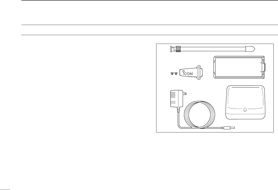
SUPPLIED ACCESSORIES
■Supplied Accessories
qAntenna* . . . . . . . . . . . . . . . . . . . . . . . . . . . . . . . . . . . . . 1
wBelt clip (with screws) . . . . . . . . . . . . . . . . . . . . . . . . . . . 1
eAC Adapter . . . . . . . . . . . . . . . . . . . . . . . . . . . . . . . . . . . 1
rBattery pack*/Battery case* . . . . . . . . . . . . . . . . . . . . . . 1
tBattery charger*. . . . . . . . . . . . . . . . . . . . . . . . . . . . . 1 set
*Not supplied with some versions.
e
q
wr
t

iv
CAUTION
To ensure that your exposure to RF electromagnetic en-
ergy is within the FCC allowable limits, always adhere to
the following guidelines:
• DO NOT operate the radio without a proper antenna at-
tached, as this may damage the radio and may also cause
you to exceed FCC RF exposure limits. A proper antenna is
the antenna supplied with this radio by the manufacturer or
an antenna specifically authorized by the manufacturer for
use with this radio.
• DO NOT transmit for more than 50% of total radio use time
(“50% duty cycle”). Transmitting more than 50% of the time
can cause FCC RF exposure compliance requirements to
be exceeded. The radio is transmitting when the “TX indica-
tor” is lit. You can cause the radio to transmit by pressing
the “PTT” switch.
• ALWAYS use Icom authorized accessories (antennas, bat-
teries, belt clips, speaker/mics, etc.). Use of unauthorized
accessories can cause the FCC RF exposure compliance
requirements to be exceeded.
• ALWAYS keep the antenna at least 2.5 cm (1 inch) away
from the body when transmitting, and only use the Icom
belt-clips which are listed in this manual when attaching the
radio to your belt, etc. To provide the recipients of your
transmission the best sound quality, hold the antenna at
least 5 cm (2 inches) from your mouth, and slightly off to one
side.
The information listed above provides the user with the
information needed to make him or her aware of RF ex-
posure, and what to do to assure that this radio operates
within the FCC RF exposure limits of this radio. Electro-
magnetic Interference/Compatibility. During transmis-
sions, your Icom radio generates RF energy that can
possibly cause interference with other devices or sys-
tems. To avoid such interference, turn off the radio in
areas where signs are posted to do so. DO NOT operate
the transmitter in areas that are sensitive to electromag-
netic radiation such as hospitals, aircraft, and blasting
sites.
SAFETY TRAINING INFORMATION

v
TABLE OF CONTENTS
FOREWORD .................................................................................... i
IMPORTANT..................................................................................... i
EXPLICIT DEFINITIONS.................................................................. i
PRECAUTION ................................................................................. ii
SUPPLIED ACCESSORIES ........................................................... iii
SAFETY TRAINING INFORMATION.............................................. iv
TABLE OF CONTENTS .............................................................. v–vi
QUICK REFERENCE................................................................... I–V
■Preparation............................................................................... I
■Your first contact..................................................................... III
■Repeater operation ................................................................ IV
■Programming memory channels............................................. V
1 ACCESSORIES...................................................................... 1–2
■Accessory attachment............................................................. 1
2PANEL DESCRIPTION .......................................................... 3–7
■Switches, controls, keys and connectors ................................ 3
■Function display ...................................................................... 6
3BATTERY PACKS................................................................ 8–12
■Battery pack replacement ....................................................... 8
■Battery caution ........................................................................ 9
■Charging NOTE ...................................................................... 9
■Battery charging .................................................................... 10
■Battery case (optional for some versions) ............................ 12
4BASIC OPERATION........................................................... 13–16
■Power ON.............................................................................. 13
■VFO mode selection.............................................................. 13
■Setting a frequency ............................................................... 13
■Setting audio/squelch level ................................................... 15
■Receive and transmit ............................................................ 15
■Display type........................................................................... 16
■Key lock function ................................................................... 16
5 REPEATER OPERATION .................................................. 17–19
■General ................................................................................. 17
■Offset frequency.................................................................... 17
■Subaudible tones .................................................................. 18
■Auto repeater function (USA versions only) .......................... 19
■Repeater lockout ................................................................... 19
6MEMORY/CALL OPERATION ........................................... 20–25
■General description ............................................................... 20
■Selecting a memory channel................................................. 20
■Selecting the call channel ..................................................... 20
■Programming the memory/call channels............................... 21
■Channel name programming................................................. 22
■Memory transferring .............................................................. 22
■Memory bank selection ......................................................... 24
■Memory bank setting............................................................. 24
■Transferring bank contents.................................................... 25
7DTMF MEMORY................................................................. 26–27
■Programming a DTMF code.................................................. 26
■Transmitting a DTMF code.................................................... 27
■DTMF transmission speed .................................................... 27

vi
8SCAN OPERATION............................................................ 28–31
■Scan types ............................................................................ 28
■Programmed scan................................................................. 28
■Memory scan..........................................................................29
■Skip channels........................................................................ 30
■Priority watch......................................................................... 30
■Scan resume condition.......................................................... 31
9SUBAUDIBLE TONES....................................................... 32–35
■Tone squelch ......................................................................... 32
■Pocket beep operation .......................................................... 34
■Tone scan.............................................................................. 35
10PAGER/CODE SQUELCH (Required Optional UT-108) .. 36–39
■Pager function....................................................................... 36
■Code programming ............................................................... 36
■Pager operation..................................................................... 38
■Code squelch ........................................................................ 39
11 DIGITAL MODE OPERATION
(Required Optional UT-118)...............................................40–56
■Digital mode operation .......................................................... 40
■Call sign programming .......................................................... 40
■Digital voice mode operation ................................................. 43
■When receiving a Digital call ................................................. 44
■Break-in communication ....................................................... 45
■EMR communication ............................................................. 46
■Pocket beep operation .......................................................... 46
■Digital squelch functions ....................................................... 47
■Digital monitor ....................................................................... 47
■Low-speed data communication ........................................... 48
■About D-STAR system .......................................................... 49
■Repeater call sign programming ........................................... 50
■Other setting items ................................................................ 51
■GPS operation ...................................................................... 55
12OTHER FUNCTIONS ......................................................... 57–67
■SET MODE............................................................................ 57
■INITIAL SET MODE .............................................................. 61
■Weather channel operation (USA versions only)................... 66
■CPU reset.............................................................................. 67
■Partial reset ........................................................................... 67
13CLONING ................................................................................. 68
14OPTIONAL UNIT................................................................ 69–70
■Optional UT-108/118 installation ........................................... 69
■Optional MB-86 installation ................................................... 69
15SPECIFICATIONS.................................................................... 71
16OPTIONS.................................................................................. 72
17CE............................................................................................. 74
1
2
3
4
5
6
7
8
9
10
11
12
13
14
15
16
17
I
QUICK REFERENCE GUIDE
■Preparation
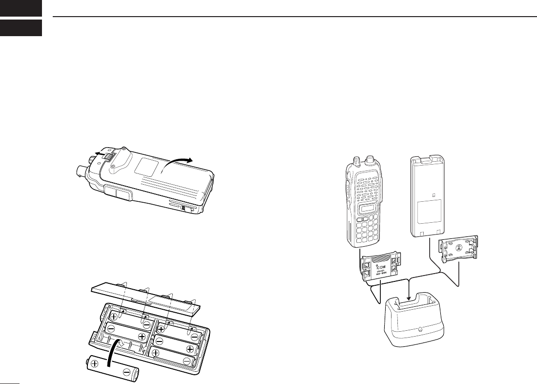
DBattery pack replacement
Before replacing the battery pack, push [PWR] for 1 sec. to
turn the power OFF.
•Slide the battery release forward, then pull the battery pack upward
with the transceiver facing away from you.
DBattery case— optional for some versions
When using a BP-208N
BATTERY CASE
attached to the trans-
ceiver, install 6 AA (LR6) size alkaline batteries as illustrated
below.
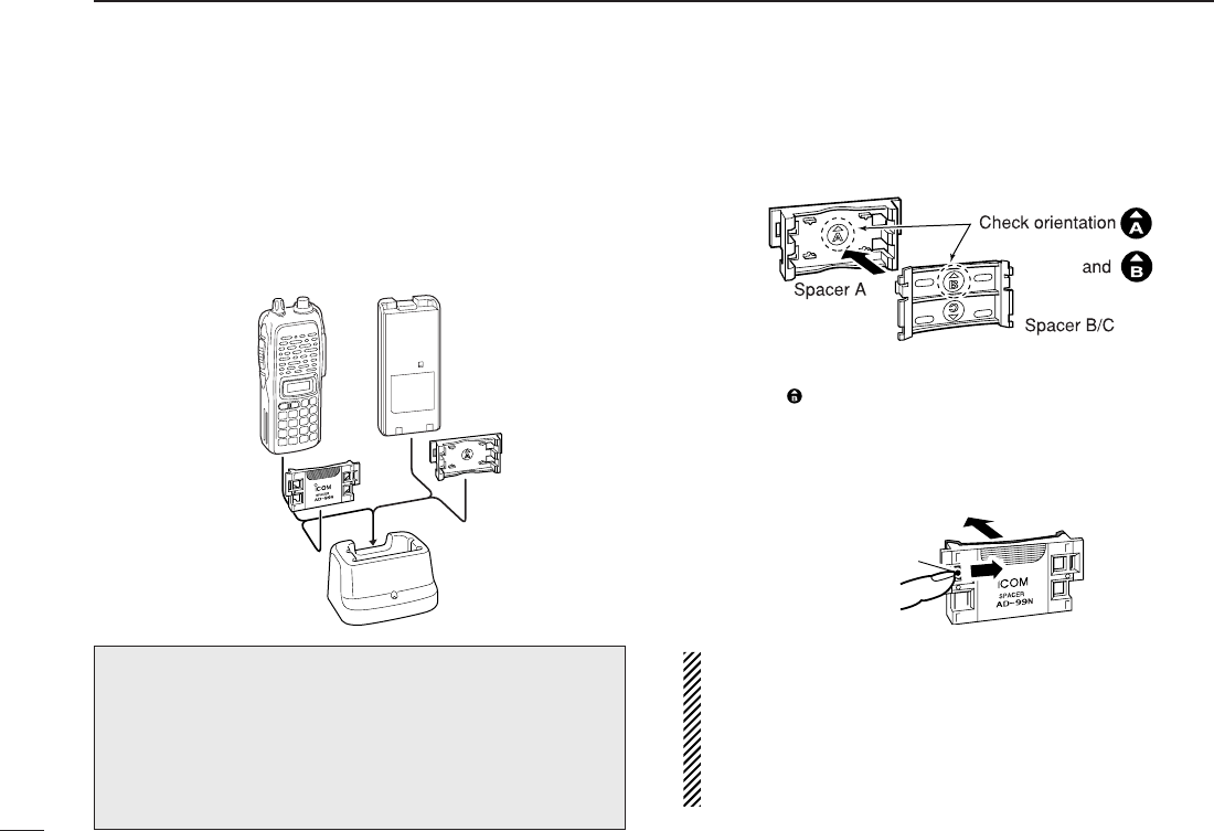
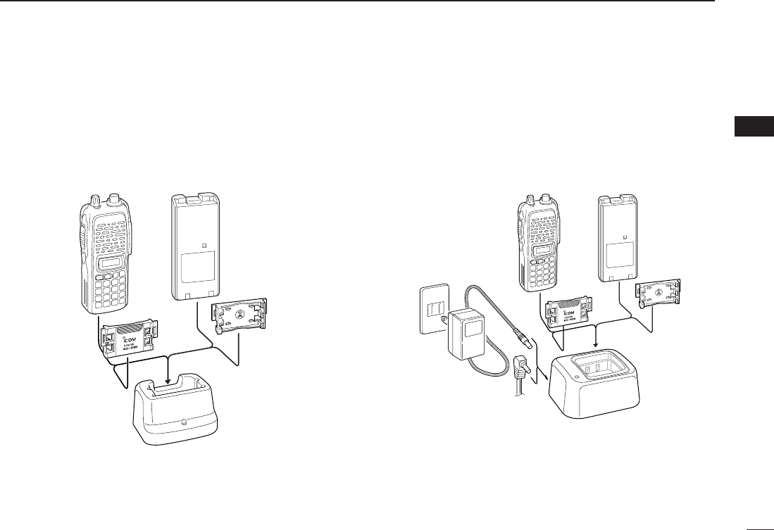
DCharging with the BC-144N/146
The optional BC-144N provides rapid charging, and the BC-
146 provides regular charging of an optional battery pack
with/without transceiver. The following is additionally required:
• An optional AC adapter. (An AD-99N is supplied with BC-144N or
BC-146.)
Check orientation
for correct charg-
ing. (Insert together
with AD-99N.)
Turn power OFF.
BC-144N/146
+AD-99N
II
QUICK REFERENCE GUIDE
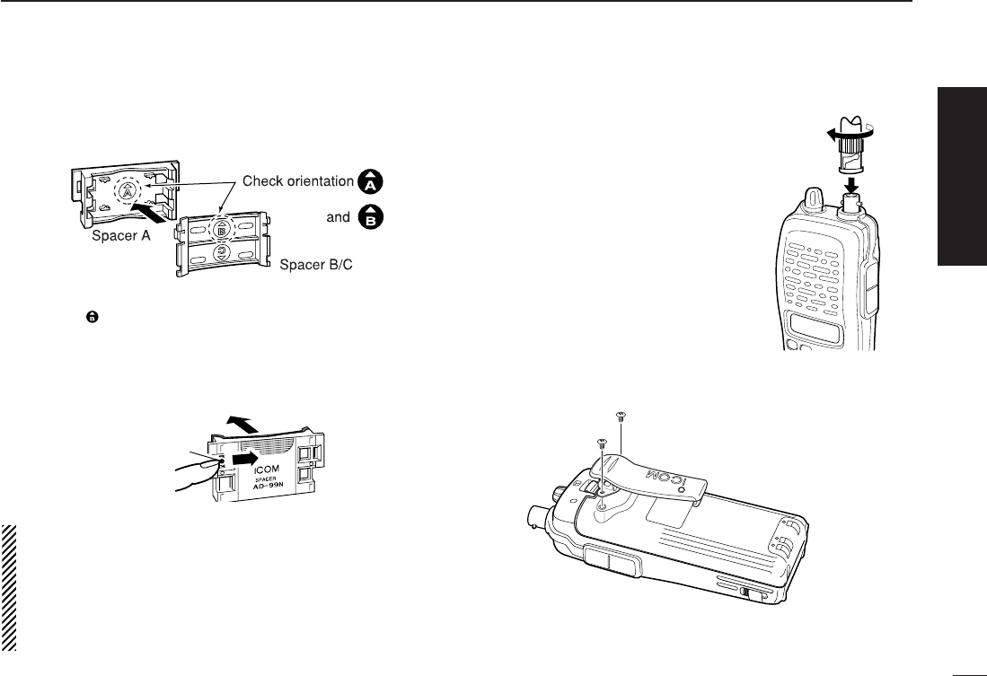
DAbout AD-99N
Attach the spacer (Spacer B/C) to the adapter (Spacer A) with
orientation as illustrated in the diagram below.
• Attach the spacer (Spacer B/C) to the adapter with the orientation of
the stamp “ ” pointing up.
When removing the spacer (Spacer B/C),
push the notch care-
fully with your finger to remove the spacer (Spacer B/C) from
the adapter (Spacer A).
RCAUTION!
DO NOT push or force the notch with a screw driver, etc., to
remove it.
DO NOT bend the notch when the adapter and spacer are not
joined together. This will cause weakening of the notch plastic.
Both cases may break the notch and it may not be able to be
reattached.
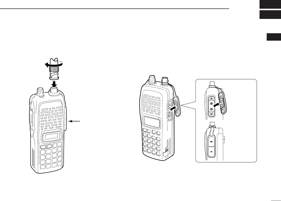
DAntenna
Attach the antenna to the transceiver
as illustrated at right.
DBelt clip
Attach the belt clip to the transceiver as illustrated below.
To attach the belt clip
Push the notch
carefully.
Remove the spacer (Spacer B/C)
from the adapter.
Quick reference guide
III
QUICK REFERENCE GUIDE
■Your first contact
Now that you have your IC-V82 ready, you are exited to get
on the air. We would like to walk you through a few basic op-
erational steps to make your first “On The Air” use an enjoy-
able experience.
DAbout default setting
The [VOL] control function can be traded with [YY]/[ZZ]keys func-
tion in
INITIAL SET MODE
. However, in this QUICK REFERENCE,
the factory default setting ([VOL] controls audio output level) is
used for simple instructions.
DBasic operation
1. Turning ON the transceiver
Although you have purchased a brand new transceiver, some
settings may be changed from the factory defaults because
of the QC process. Resetting the CPU is necessary to start
from factory default.
➥While pushing [MONI] and
[D•
CLR
], push [PWR] for 1 sec. to
reset the CPU and turn power ON.
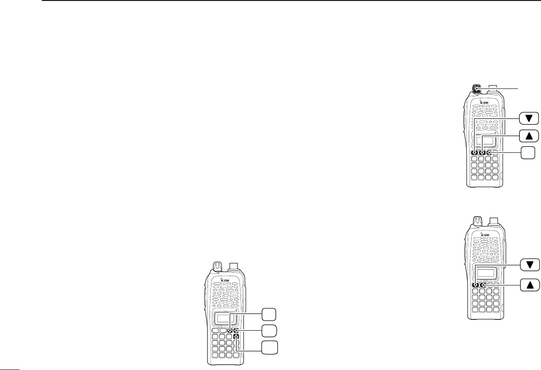
2. Adjusting sudio output level
➥Rotate [VOL] to set the desired
audio level.
3. Adjusting the squelch level
➥While pushing and holding
[MONI], push [YY]or [ZZ]to set the
squelch level.
4. Tune the desired frequency
The up/down keys, [YY]/[ZZ], will
allow you to tune the frequency that
you want to operate on. Page 14 will
instruct you on how to adjust the tun-
ing step.
➥
Push [YY]or [ZZ]to adjust the fre-
quency.
PWR
MONI
CLR
D
MONI
[VOL]
IV
QUICK REFERENCE GUIDE
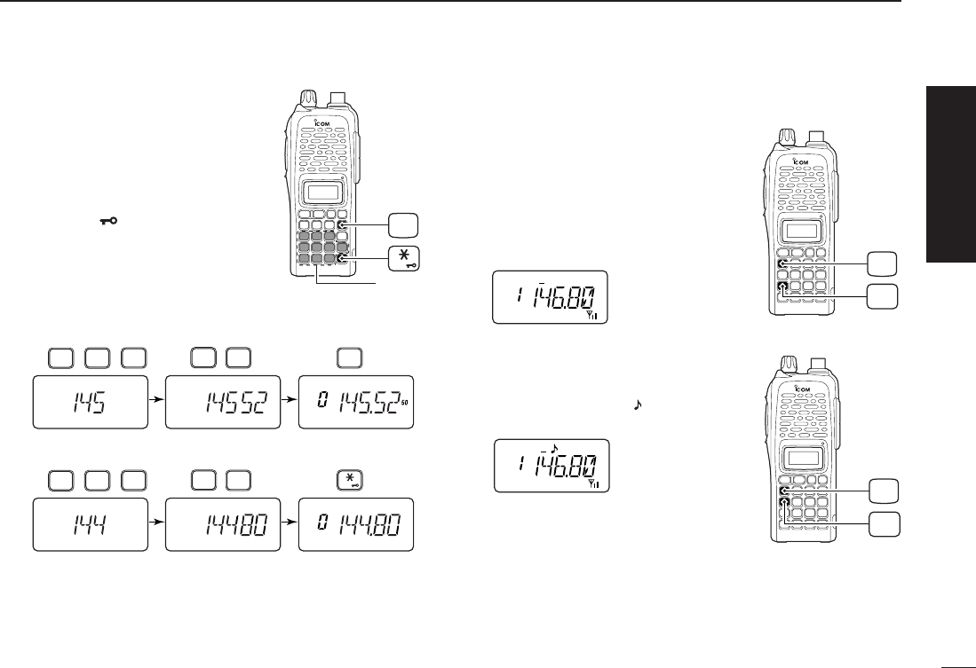
Direct frequency input from the key-
pad is also available.
➥To enter the desired frequency,
enter 6-digits starting from the
100 MHz digit.
•Enter three* to five digits then push-
ing [✱•
ENT
]is also set the fre-
quency. (*Some versions are
available from two digits.)
•When a digit is mistakenly input,
push [D.
CLR
]to abort to input.
5. Transmit and receive
➥Push and hold [PTT] to transmit, then speak into the mi-
crophone; release to receive.
■Repeater operation
1. Setting duplex
➥Push [A•
FUNC
], then [4•
DUP
]sev-
eral times to select minus duplex
or plus duplex.
•The USA version has an auto re-
peater function, therefore, setting du-
plex is not required.
2. Repeater tone
➥Push [A•
FUNC
], then [1•
TONE
]
several times until “ ” appears, if
required.
TONE
1
FUNC
A
DUP
4
FUNC
A
• Example 1— when entering 145.525 MHz
Push
• Example 2— when entering 144.800 MHz
P.BEEP
2
DUP
4
DUP
TONE
4
1
SCAN
5
SCAN
5
SCAN
5
Push
DUP
TONE
4
1
OPT
0
SET
8
ENT
CLR
D
Keypad
ENT
Quick reference guide
V
QUICK REFERENCE GUIDE
The IC-V82 has a total of 207 memory channels (including 6
scan edges and 1 call channel) for storing often used operat-
ing frequency, repeater settings, etc.
1. Setting frequency
In VFO mode, set the desired operating frequency with other
desired settings, such as repeater and subaudible tone.
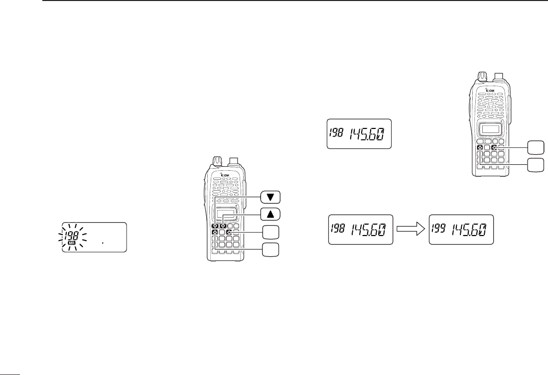
2. Selecting a memory channel
➥Push [A•
FUNC
], [C•
MR
]then push
[YY] or [ZZ]several times to select
the desired memory channel.
•“
X” indicator and memory channel
number blink.
3. Writing a memory channel
➥Push [A•
FUNC
], then push [C•
MR
]
for 1 sec. to program.
•3 beeps sound
•Continue to hold [C•
MR
]down for 1 sec. after 3 beeps are emit-
ted, to increment the displayed memory channel number.
MR
C
FUNC
A
MR
C
FUNC
A
■Programming memory channels
1
1
ACCESSORIES
1
■Accessory attachment
DAntenna
Attach the antenna to the transceiver as illustrated below. Keep the [SP/MIC] cap (SP/MIC jack cover) attached when
jacks are not in use to avoid bad contacts.
Attach the
[SP/MIC] cap.
[SP/MIC] cap

2
1ACCESSORIES
DBelt clip
Attach the belt clip to the transceiver as illustrated below.
To attach the belt clip
DHandstrap (Not supplied)
Slide the hand strap through the loop on the top of the rear
panel as illustrated below. Facilitates carrying.
3
2
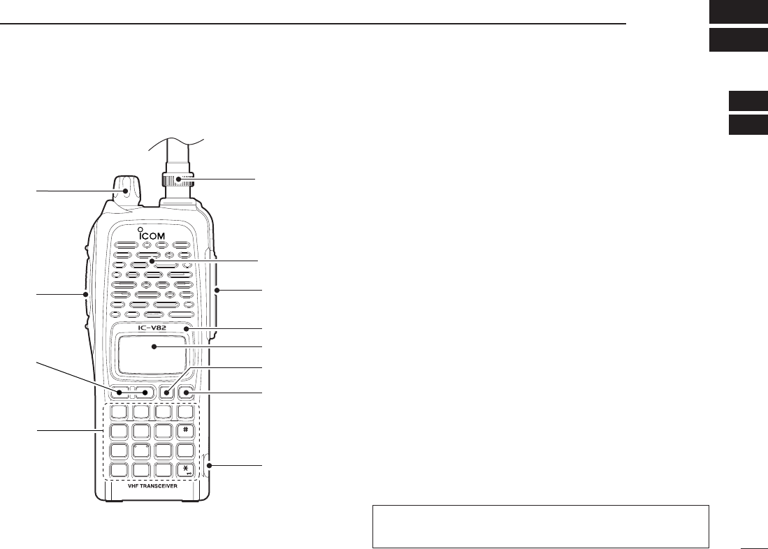
PANEL DESCRIPTION
1
2
qCONTROL DIAL [VOL]
*Rotate to adjust the volume level.
wPTT SWITCH [PTT]
Push and hold to transmit; release to receive.
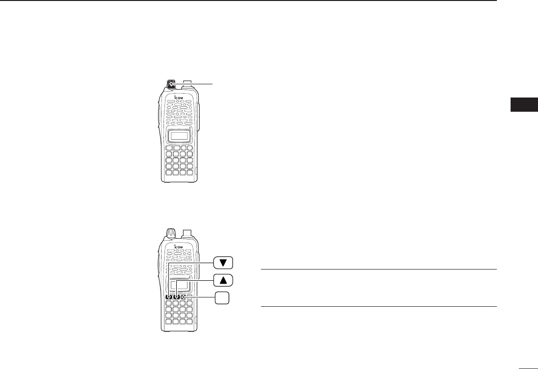
eUP/DOWN KEYS [YY]/[ZZ]
*Selects the operating frequency.
rKEY PAD (pgs. 4, 5)
Used to enter operating frequency, the DTMF codes, etc.
tANTENNA CONNECTOR
Connects the supplied antenna.
y[SP]/[MIC] JACK
Connect an optional speaker-microphone or headset, if de-
sired. The internal microphone and speaker will not func-
tion when either is connected.
uFUNCTION DISPLAY (pgs 6, 7)
iSQUELCH/MONITOR SWITCH [MONI]
Push and hold to force the squelch open and set the trans-
ceiver to the squelch level adjustable condition.
oPOWER SWITCH [PWR]
Push for 1 sec. to turn the power ON and OFF.
MONI
CALL
DUP SCAN
PRIO
ENT
SET
H/M/L
OPTSKIP
BANK
TONE
T.SCANP.BEEP
MR CLRFUNC
PWR
987
4
123
AB DC
560
q
w
t
Microphone
Speaker
y
!0
o
u
i
e
r
■Switches, controls, keys and connectors
*The assigned function for [VOL] and [YY]/[ZZ]can be
traded in
INITIAL SET MODE
(pgs. 14, 63).
4
2PANEL DESCRIPTION
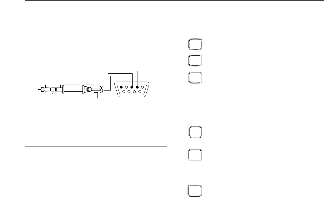
!0 [DATA] JACK
Connect to a PC or GPS receiver via the RS232C cable (D-
sub 9 pin) for data communication in the RS-232C format.
DKey pad
[A•
FUNC
]
Access to secondary function.
[B•
CALL
]
Select the call channel. (p. 20)
[C•
MR
]
➥Selects a memory mode. (p. 20)
➥After pushing [A•
FUNC
], entering into memory
programming/editing mode. (pgs. 21–23)
➥After pushing [A•
FUNC
], programs/transfers
VFO/memory or call channel contents into
memory channel/VFO when pushed for 1 sec.
(pgs. 21–23)
[D•
CLR
]
Selects VFO mode, aborts direct frequency input,
or cancels scanning, etc. (pgs. 13, 28)
[1•
TONE
]
➥Input digit “1” during frequency input, memory
channel selection, etc. (pgs. 13, 20)
➥After pushing [A•
FUNC
], selects the subaudible
tone function. (pgs. 17, 32)
[2•
P
.
BEEP
]
➥Input digit “2” during frequency input, memory
channel selection, etc. (pgs. 13, 20)
➥After pushing [A•
FUNC
], turn the pocket beep
function ON and OFF. (p. 34)
P.BEEP
2
TONE
1
CLR
D
MR
C
CALL
B
FUNC
A
Pin 2 (RxD),
Pin 3 (TxD),
Pin 5 (GND)
to [DATA] jack
TxD
2.5(d) mm Less than
10(d) mm
GND
RxD
1
5
69
RS-232C
(DB-9 female)
Make sure the connection between transceiver and PC, oth-
erwise misreading may occur for data communication.

5
2
PANEL DESCRIPTION
2
[3•
T
.
SCAN
]
➥Input digit “3” during frequency input, memory
channel selection, etc. (pgs. 13, 20)
➥After pushing [A•
FUNC
], starts the tone scan-
ning. (pgs. 18, 35)
[4•
DUP
]
➥Input digit “4” during frequency input, memory
channel selection, etc. (pgs. 13, 20)
➥After pushing [A•
FUNC
], selects a duplex func-
tion (–duplex, +duplex, simplex). (p. 17)
[5•
SCAN
]
➥Input digit “5” during frequency input, memory
channel selection, etc. (pgs. 13, 20)
➥After pushing [A•
FUNC
], starts scanning. (p. 28)
[6•
SKIP
]
➥Input digit “6” during frequency input, memory
channel selection, etc. (pgs. 13, 20)
➥After pushing [A•
FUNC
], sets and cancels skip
setting for memory skip scan during memory
mode. (p. 30)
[7•
PRIO
]
➥Input digit “7” during frequency input, memory
channel selection, etc. (pgs. 13, 20)
➥After pushing [A•
FUNC
], starts the priority
watch. (p. 30)
[8•
SET
]
➥Input digit “8” during frequency input, memory
channel selection, etc. (pgs. 13, 20)
➥After pushing [A•
FUNC
], enters into
SET MODE
.
(p. 57)
[9•
H
/
M
/
L
]
➥Input digit “9” during frequency input, memory
channel selection, etc. (pgs. 13, 20)
➥After pushing [A•
FUNC
], switches transmit
power from high, middle and low output power.
(p. 15)
[0•
OPT
]
➥Input digit “0” during frequency input, memory
channel selection, etc. (pgs. 13, 20)
➥After pushing [A•
FUNC
], selects an optional
function mode, such as pager, code squelch or
digital operation. (pgs. 38, 40)
[#•
BANK
]
After pushing [A•
FUNC
], enters a memory bank
condition. (p. 24)
[✱•
ENT
]
➥Sets the frequency even if the full 6-digits of
frequency have not been entered. (p. 13)
➥After pushing [A•
FUNC
], switches key lock func-
tion ON and OFF when pushed for 1 sec. Lock
all keys, except [PWR], [PTT], [MONI] and
audio level adjustment. (p. 16)
ENT
BANK
OPT
0
H/M/L
9
SET
8
PRIO
7
SKIP
6
SCAN
5
DUP
4
T.SCAN
3
6
2PANEL DESCRIPTION
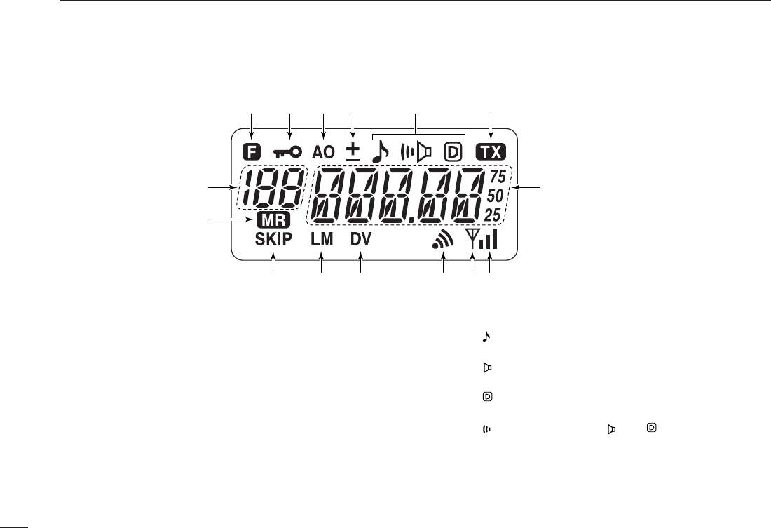
■Function display
qFUNCTION INDICATOR
Appears while a secondary function is being accessed.
wKEY LOCK INDICATOR (p. 16)
Appears when the key lock function is ON.
eAUTO POWER OFF INDICATOR (p. 62)
Appears while the auto power OFF function is activated.
rDUPLEX INDICATOR (p. 17)
Either “–” or “+” appears during repeater operation.
tTONE INDICATOR
❍While in the analog (FM) mode operation
➥“” appears while the subaudible tone encoder is in
use. (p. 17)
➥“” appears while the tone (CTCSS) squelch func-
tion is in use. (p. 32)
➥“” appears while the tone (DTCS) squelch function
is in use. (p. 32)
➥“” appears with the “ ” or “ ” indicator while the
pocket beep function (CTCSS or DTCS) is in use.
(p. 34)
qqqwqeqrt qy
u
!5
!4
!3 !2 !1 io!0

7
2
PANEL DESCRIPTION
2
❍While in the digital (DV) mode operation with the in-
stalling an optional Digital unit UT-118.
➥“” appears while the digital code (CSQL) squelch
function is in use. (p. 47)
➥“” appears while the call sign (DSQL) squelch func-
tion is in use. (p. 47)
➥“” appears with the “ ” or “ ” indicator while the
pocket beep function (CSQL or DSQL) is in use.
(p. 46)
yTRANSMIT INDICATOR (p. 15)
Appears during transmit.
uFREQUENCY READOUT
Shows operating frequency, channel number or channel
names, depending on display type (p. 16).
iSIGNAL INDICATOR
➥Shows receiving signal strength as below.
➥Shows the output power level while transmitting.
oBUSY INDICATOR
➥Appears when a signal is being received or the squelch
is open.
➥Blinks while the monitor function is activated. (pgs.15,
47)
!0 PAGER CALL INDICATOR (p. 39)
Blinks when a pager call is received. (This indicator ap-
pears only when UT-108 is installed.)
!1 DIGITAL MODE INDICATOR (p. 43)
Appears when digital mode is selected. (This indicator ap-
pears only when UT-118 is installed.)
!2 LOW/MIDDLE POWER INDICATOR (p. 15)
➥“L” or “M” appears when the low or middle output power
is selected, respectively.
➥No indicator appears when high output power is se-
lected.
!3 SKIP CHANNEL INDICATOR (p. 30)
Appears when the selected memory channel is specified
as a skip channel.
!4MEMORY MODE INDICATOR (p. 20)
Appears while in memory mode or channel number indica-
tion mode.
!5MEMORY CHANNEL INDICATOR (p. 20)
➥Shows the selected memory channel number.
➥“C” appears when the call channel is selected.
Low Middle High
Weak ⇐ RX Signal level ⇒ Strong
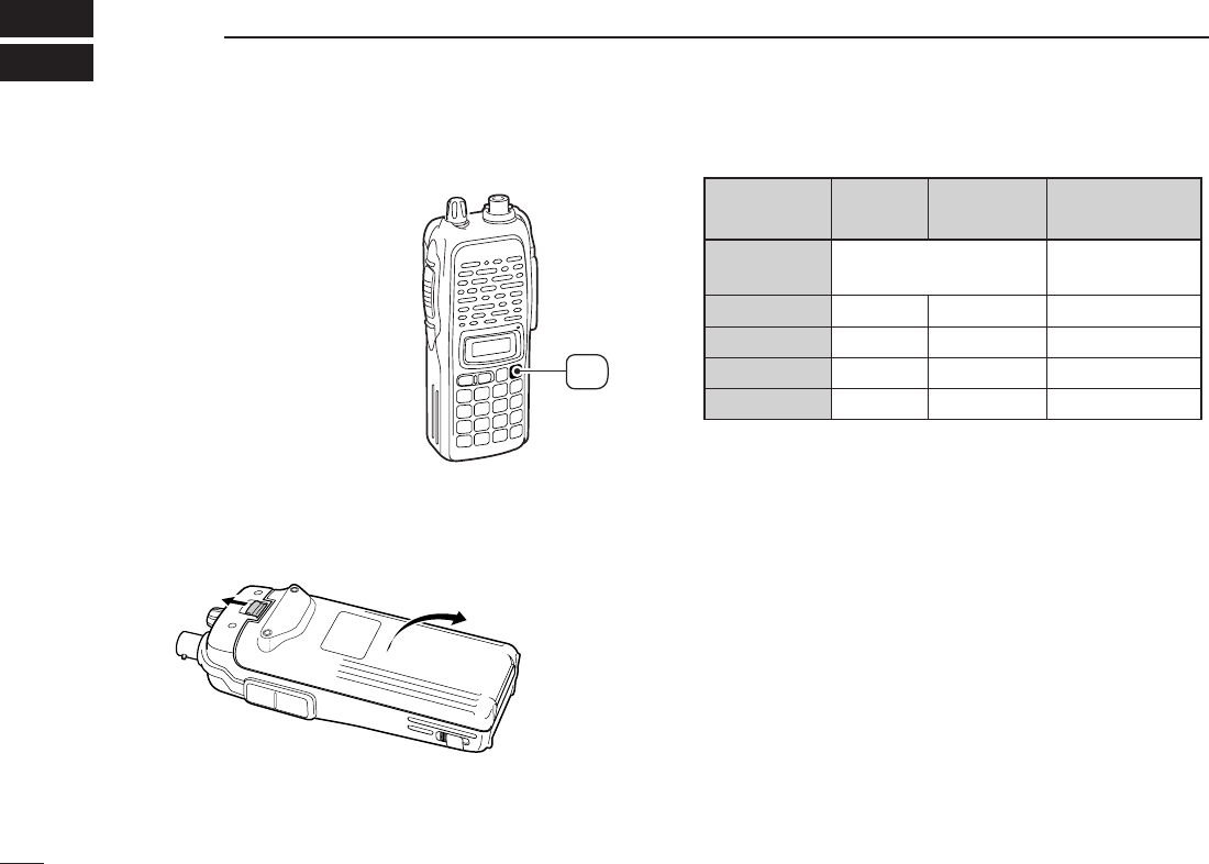
■Battery pack replacement
➥Before replacing the battery
pack, push [PWR] for 1 sec.
to turn the power OFF.
➥Slide the battery release forward, then pull the battery pack
upward with the transceiver facing away from you.
DDBATTERY PACKS
*1Operating periods are calculated under the following conditions;
Tx : Rx : standby =1 : 1 : 8, power save function: auto setting is
activated
*2Operating period depends on the alkaline cells used.
Battery Voltage Capacity Battery life*1
pack
BP-208N Battery case for AA —*2
(LR6)×6 alkaline
BP-209N 7.2 V 1100 mAh 3 hrs. 20 min.
BP-210N 7.2 V 1650 mAh 6 hrs.
BP-211N 7.4 V 1800 mAh 6 hrs. 10 min.
BP-222N 7.2 V 600 mAh 2 hrs. 15 min.
Push
for 1 sec.
PWR
8
BATTERY PACKS
3

9
3
BATTERY PACKS
3
■Battery caution
RDANGER! Use/Charge the specified Icom batteries only.
Only tested and approved for use with genuine Icom bat-
teries. Fire and/or explosion may occur when a third party
battery pack or counterfeit product is used/charged.
• CAUTION! NEVER short the terminals of the battery pack
(or charging terminals of the transceiver). Also, current may
flow into nearby metal objects such as a necklace, so be
careful when placing battery packs (or the transceiver) in
handbags, etc.
Simply carrying with or placing near metal objects such as a
necklace, etc. causes shorting. This will damage not only
the battery pack, but also the transceiver.
• NEVER incinerate used battery packs. Internal battery gas
may cause an explosion.
• NEVER immerse the battery pack in water. If the battery
pack becomes wet, be sure to wipe it dry BEFORE attach-
ing it to the transceiver.
• Clean the battery terminals to avoid rust or poor contact.
• Keep battery contacts clean. It’s a good idea to clean bat-
tery terminals once a week.
If your battery pack seems to have no capacity even after
being charged, completely discharge it by leaving the power
ON overnight. Then, fully charge the battery pack again. If the
battery pack still does not retain a charge (or only very little
charge), a new battery pack must be purchased (p. 70).
■Charging NOTE
Prior to using the transceiver for the first time, the battery
pack must be fully charged for optimum life and operation.
• Recommended temperature range for charging:
+10°C to +40°C (; +50˚F to 140˚F)
• Use the supplied charger or optional charger (BC-119N/121N/144N
for rapid charging, BC-146 for regular charging) only. NEVER use
other manufacturers’ chargers.
The optional BP-222N, BP-209N, BP-210N or BP-211N bat-
tery packs include rechargeable batteries (Ni-Cd: BP-222N,
BP-209N, Ni-MH: BP-210N, Li-Ion: BP-211N) and can be
charged approx. 300 times. Charge the battery pack before
first operating the transceiver or when the battery pack be-
comes exhausted.
If you want to charge the battery pack more than 300 times,
the following points should be observed:
• Avoid over charging. The charging period should be less than
24 hours.
• Use the battery until it becomes almost completely exhausted
under normal conditions. We recommend battery charging after
transmitting becomes impossible.
DDBattery pack life
When the operating period becomes extremely short even
after charging the battery pack fully, a new battery pack is
needed.
10
3BATTERY PACKS
■Battery charging
DRegular charging with the BC-146
The optional BC-146 provides regular charging of an optional
NI-Cd battery pack with/without transceiver. The following is
additionally required:
• An optional AC adapter. (An AD-99N is supplied with BC-146.)
DAbout AD-99N
Attach the spacer (Spacer B/C) to the adapter (Spacer A) with
orientation as illustrated in the diagram below.
• Attach the spacer (Spacer B/C) to the adapter with the orientation of
the stamp “ ” pointing up.
When removing the spacer (Spacer B/C),
push the notch care-
fully with your finger to remove the spacer (Spacer B/C) from
the adapter (Spacer A).
RCAUTION!
DO NOT push or force the notch with a screw driver, etc., to
remove it.
DO NOT bend the notch when the adapter and spacer are not
joined together. This will cause weakening of the notch plastic.
Both cases may break the notch and it may not be able to be
reattached.
Push the notch
carefully.
Remove the spacer (Spacer B/C)
from the adapter.
Check orienta-
tion for correct
charging. (In-
sert together
with AD-99N.)
Turn power OFF.
BC-146 +AD-99N
• Chargeable battery
BP-209N, BP-222N
Recommendation:
Charge the BP-211N (Li-Ion) by BC-119N (or BC-121N) for
a maximum of 2 hours. Li-Ion batteries are different from Ni-
Cd batteries in that it is not necessary to completely charge
and discharge them to prolong the battery life. Therefore,
charging the battery in intervals, and not for extended peri-
ods is recommended.
11
3
BATTERY PACKS
3
DRapid charging with the BC-144N
The optional BC-144N provides rapid charging of optional
battery packs.
The following are additionally required:
• An AC adapter (may be supplied with the BC-144N depending on
version).
• Chargeable battery
BP-210N (Ni-MH battery)
BP-209N, BP-222N (Ni-Cd batteries)
DRapid charging with the BC-119N+AD-101
The optional BC-119N provides rapid chaging of battery
packs. The following items are additionally required.
• AD-101.
• An AC adapter (may be supplied with the BC-119N depending on
version) or the DC power cable (OPC-515L/CP17L).
• Chargeable battery
BP-210N (Ni-MH battery)
BP-209N, BP-222N (Ni-Cd batteries)
BP-211N (Li-Ion battery)
DC power cable (OPC-515L)
(Connect with the DC power supply;
13.8 V/at least 2 A)
Turn power OFF.
Check orienta-
tion for correct
charging. (In-
sert together
with AD-99N.)
Turn power OFF.
BC-144N +AD-99N
12
3BATTERY PACKS
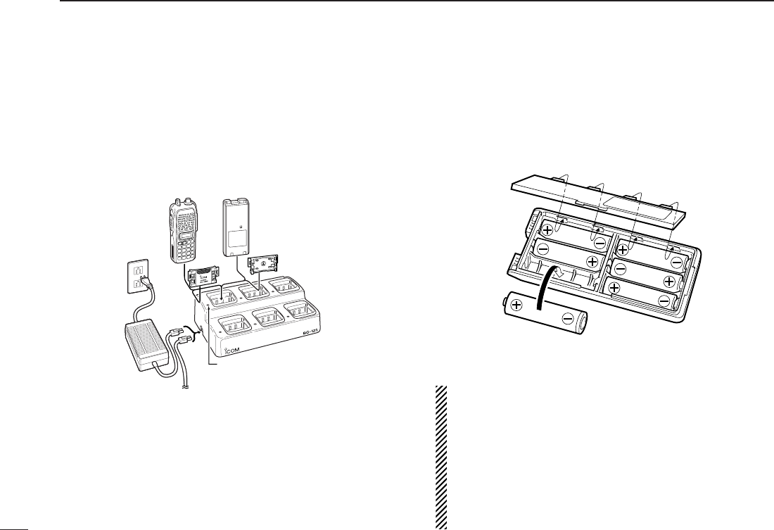
DRapid charging with the BC-121N+AD-101
The optional BC-121N allows up to 6 battery packs to be
charged simultaneously. The following items are additionally
required.
• Six AD-101.
• An AC adapter (BC-124; may be supplied with the BC-121N de-
pending on version) or the DC power cable (OPC-656).
• Chargeable battery
BP-210N (Ni-MH battery)
BP-209N, BP-222N (Ni-Cd batteries)
BP-211N (Li-Ion battery)
■Battery case
(optional for some versions)
When using a BP-208N BATTERY CASE attached to the
transceiver, install 6 AA (LR6) size alkaline batteries as illus-
trated below.
DDCAUTION
• Use ALKALINE batteries only.
• Make sure all battery cells are the same brand, type and ca-
pacity.
• Never mix old and new batteries.
Either of the above may cause a fire hazard or damage the
transceiver if ignored.
• Never incinerate used battery cells since internal battery gas
may cause them to rupture.
• Never expose a detached battery case to water.
If the battery case gets wet, be sure to wipe it dry before use.
MULTI-CHARGER
AC adapter
(purchased
separately)
DC power cable (OPC-656)
(Connect with the DC power supply;
13.8 V/at least 7 A)
Charge indicator
(each indicator functions independently)
Turn power OFF.
13
4
BASIC OPERATION
3
4
■Power ON
➥Push [PWR] for 1 sec. to turn
power ON.
■VFO mode selection
The transceiver has 2 basic oper-
ating modes: VFO mode and
memory mode.
➥Push [D•
CLR
]to select VFO
mode.
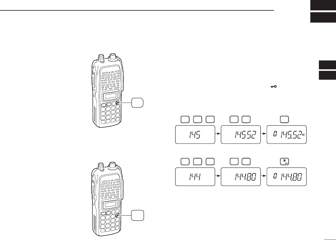
■Setting a frequency
DVia the keypad
qPush [D•
CLR
]to select VFO mode, if necessary.
wTo enter the desired frequency, enter 6-digits starting from
the 100 MHz digit.
•Enter three* to five digits then pushing [✱•
ENT
]is also set the
frequency. (*Some versions are available from two digits.)
•When a digit is mistakenly input, push [D.
CLR
]to abort to input.
• Example 1— when entering 145.525 MHz
Push
• Example 2— when entering 144.800 MHz
P.BEEP
2
DUP
4
DUP
TONE
4
1
SCAN
5
SCAN
5
SCAN
5
Push
DUP
TONE
4
1
OPT
0
SET
8
ENT
CLR
D
Push
for 1 sec.
PWR
DBy other methods
Via the [YY]/[ZZ] keys
➥Push [YY]or [ZZ]several times to set the desired frequency.
•Each push increases/decreases the frequency by the selected
tuning step. See right content for tuning step details.
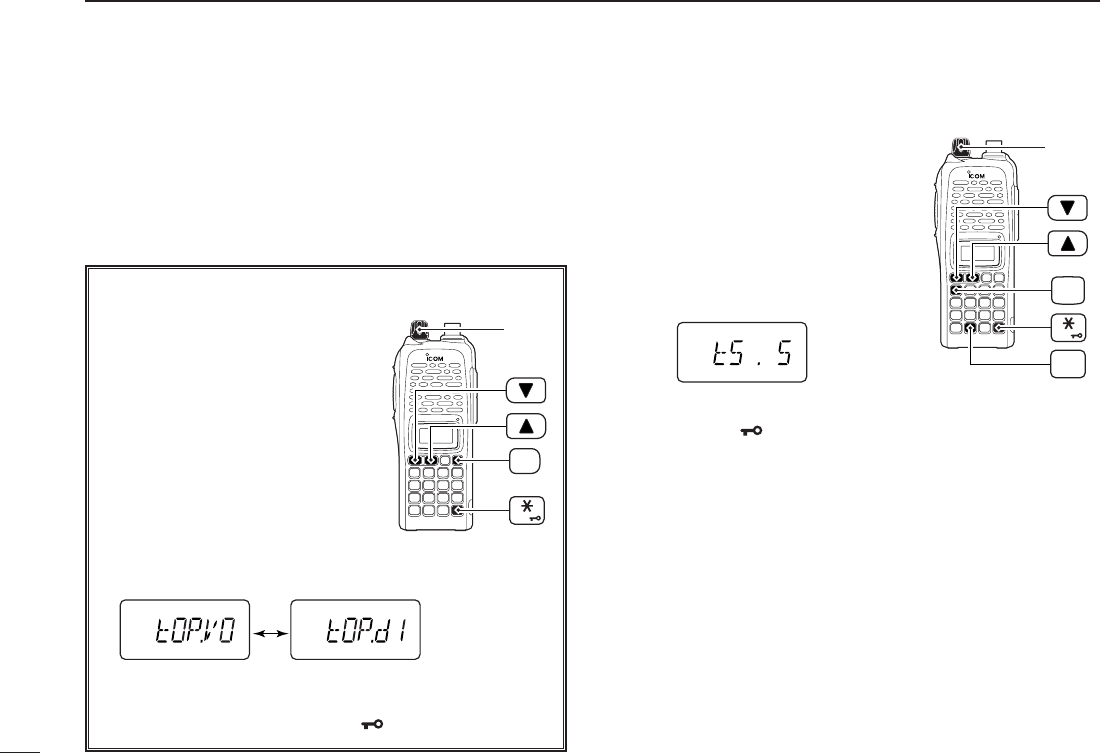
DTuning step selection
The IC-V82 has 8 tuning steps— 5,
10, 12.5, 15, 20, 25, 30 and 50 kHz.
The tuning step is selectable in
SET
MODE
.
qPush [A•
FUNC
]then [8•
SET
]to
enter
SET MODE
.
wPush [YY]or [ZZ]several times to
select the tuning step item.
eRotate [VOL] to select the desired tuning step.
rPush [✱•
ENT
]to exit
SET MODE
.
[VOL]
ENT
FUNC
A
SET
8
14
4BASIC OPERATION
✔For your information— [VOL] function assignment
The [VOL] control can be used as
a tuning dial for frequency tuning in-
stead of [YY]/[ZZ]keys. However,
while [VOL] functions as tuning
dial, [YY]/[ZZ]keys functions as AF
volume control.
qWhile pushing [YY]and [ZZ], turn
power ON to enter
INITIAL SET
MODE
.
wPush [YY]or [ZZ]several times to
select the dial assignment item, “tOP.”
eRotate [VOL] to select the condition.
rTo exit
SET MODE
, push [✱•
ENT
].
[VOL] is assigned as
AF volume control. [VOL] is assigned as
tuning dial.
[VOL]
ENT
PWR
15
4
BASIC OPERATION
4
■Setting audio/squelch level
DTo set the audio level
Rotate [VOL] to set the desired
audio level while receiving a sig-
nal.
• When no signal is received, push
and hold [MONI] while setting the
audio level.
• When [VOL] is assigned as tuning
dial, push [YY]/[ZZ]to adjust the audio
output level. (pgs. 14, 63)
DTo set the squelch level
While pushing [MONI], push
[YY]/[ZZ]to set the squelch level.
• The squelch level “1” is loose
squelch, “10” is tight squelch.
• When [VOL] is assigned as tuning
dial, rotate [VOL] while [MONI] is
pushed. (pgs. 14, 63)
■Receive and transmit
qPush [PWR] for 1 sec. to turn the power ON.
wAdjust audio volume to the desired level.
eSet a frequency.
When a signal is received:
• Squelch opens and audio is emitted from the speaker.
• Signal indicator shows the relative signal strength level.
rPush [A•
FUNC
], then [9•
H
/
M
/
L
]to select output power be-
tween high, middle and low.
•“L” appears when low power is selected.
•“M” appears when middle power is selected.
•No indication appears when high power is selected.
tPush and hold [PTT] to transmit, then speak into the micro-
phone.
• “$” appears.
•Do not hold the microphone too close to your mouth or
speak too loudly. This may distort the signal.
yRelease [PTT] to receive.
✔For your information— Monitor function:
Push and hold [MONI] to listen to weak signals that do not
open the squelch.
MONI
[VOL]
16
4BASIC OPERATION
■Display type
The transceiver has 3 display types to suit your operating
style.
The display type is selected in
INITIAL SET MODE
(p. 63).
“Frequency Indication” type
Displays operating frequency.
“Channel Number Indication” type
Displays memory channel number. In this type only pre-
programmed memory channel numbers are displayed.
VFO mode cannot be selected.
• When the channel indication type is selected, only the following
functions can be performed.
- Scan function (p. 28)
- Output power setting (p. 15)
- DTMF memory function (p. 26)
- Key lock function (see right content)
- Scan pause timer setting, function key timer setting and LCD
backlight setting in
SET MODE
(p. 59)
“Channel Name Indication” type
Displays memory channel name you have assigned. In this
display pre-programmed memory channel names are dis-
played.
VFO mode is selectable.
• Programmed frequencies are indicated pre-programmed in the
selected memory channel.
• Push and hold [MONI] to display the operating frequency.
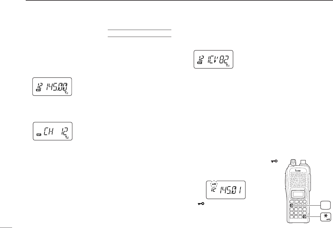
■Key lock function
The key lock function prevents accidental frequency changes
and function activation.
Push [A•
FUNC
]then push [✱•
ENT
]
for 1 sec. to toggle the function ON and
OFF.
•“ ” appears while the lock function is
activated.
•[PWR], [PTT], [VOL] and [MONI] can
be operated regardless of this setting.
USING
INITIAL SET MODE
FUNC
A
ENT
17
5
REPEATER OPERATION
4
5
■General
When using a repeater, the transmit frequency is shifted from
the receive frequency by the offset frequency. It is convenient
to program repeater information into memory channels.
qSet the receive frequency (repeater output frequency).
wPush [A•
FUNC
]and [4•
DUP
]several times to select “–” or
“+.”
•“–” indicates the transmit frequency is shifted down; “+” indicates
the transmit frequency is shifted up.
• Blinking “–” or “+” indicates the reversed duplex mode is selected
in
SET MODE
(p. 58).
ePush [A•
FUNC
]and [1•
TONE
]several times to activate the
subaudible tone encoder, if required.
•“ ” appears.
•Select the desired subaudible tone frequency, if necessary.
(p. 18)
rPush and hold [PTT] to transmit.
•The displayed frequency automatically changes to the transmit
frequency (repeater input frequency).
•If “OFF” appears, check the offset frequency (see right content
for details) and direction.
tRelease [PTT] to receive.
yPush and hold [MONI] to check whether the other station’s
transmit signal can be directly received or not.
About reversed duplex mode
When the reversed duplex mode is selected, the receive
frequency shifts. (Transmit frequency shifts in normal du-
plex mode.)
Each receive and transmit frequency is shown in the table
below with the following conditions;
Inputed freq.: 145.30 MHz
Direction : – (negative)
Offset frequency : 0.6 MHz
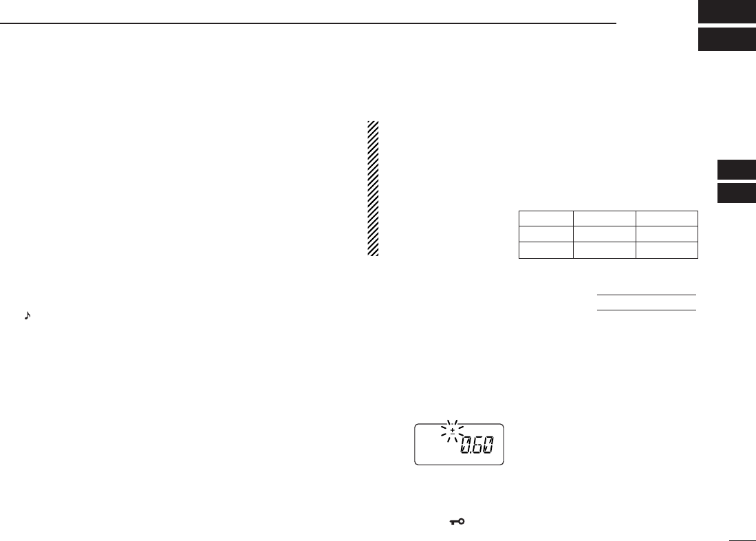
■Offset frequency
When communicating through a repeater, the transmit fre-
quency is shifted from the receive frequency by an amount
determined by the offset frequency.
qPush [A•
FUNC
], then push [8•
SET
]to enter
SET MODE
.
wPush [YY]or [ZZ]several times until “±” and offset frequency
appear.
eRotate [VOL] to select the desired offset frequency.
•Selectable steps are the same as the pre-set tuning steps.
•The unit of the displayed offset frequency is “MHz.”
rPush [✱•
ENT
](or [D•
CLR
]) to fix the offset frequency and
exit
SET MODE
.
USING
SET MODE
Reversed OFF ON
Rx freq. 145.30 MHz 144.70 MHz
Tx freq. 144.70 MHz 145.30 MHz
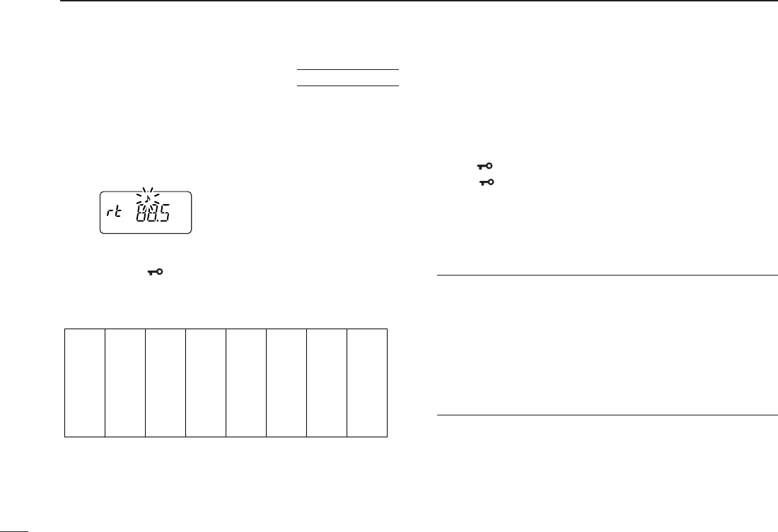
■Subaudible tones
Some repeaters require subaudible tones to be accessed.
Subaudible tones are superimposed over your normal signal
and must be set in advance.
qPush [A•
FUNC
], then push [8•
SET
]to enter
SET MODE
.
wPush [YY]or [ZZ]one or more times until “rt” appears.
eRotate [VOL] to select the desired subaudible tone.
rPush [✱•
ENT
](or [D•
CLR
]) to fix the selected tone and
exit
SET MODE
.
• Available subaudible tone frequencies (unit: Hz)
DDTone information
Some repeaters require another tone system to be accessed.
DTMF TONES
While pushing [PTT], push the desired DTMF keys (0–9,
[A•
FUNC
], [B•
CALL
], [C•
MR
], [D•
CLR
], [#•
BANK
]and
[✱•
ENT
]) to transmit DTMF tones.
•[✱•
ENT
]enters as “E”, [#•
BANK
]enters as “F.”
•The transceiver has 16 DTMF memory channels (p. 26).
1750 Hz TONE
While pushing [PTT], push [YY]or [ZZ]to transmit a 1750 Hz
tone signal.
✔Convenient
Tone scan function: When you don’t know the subaudible
tone used for a repeater, the tone scan is convenient for de-
tecting the tone frequency.
Push [A•
FUNC
], then push [3•
T
.
SCAN
]to start the tone scan.
• Push [D•
CLR
]to cancel the scan.
• When the required tone frequency is detected, the scan
pauses.
67.0
69.3
71.9
74.4
77.0
85.4
88.5
91.5
94.8
97.4
100.0
103.5
79.7
82.5
107.2
110.9
114.8
118.8
123.0
127.3
131.8
136.5
141.3
146.2
151.4
156.7
159.8
162.2
165.5
167.9
171.3
173.8
177.3
179.9
183.5
186.2
189.9
192.8
196.6
199.5
203.5
206.5
210.7
218.1
225.7
229.1
233.6
241.8
250.3
254.1
USING
SET MODE
18
5REPEATER OPERATION
19
5
REPEATER OPERATION
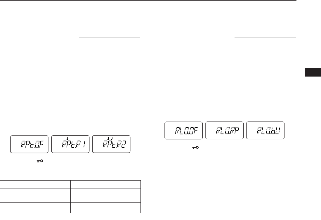
■Auto repeater function
(USA version only)
The USA version automatically activates the repeater settings
(duplex, ON/OFF, duplex direction, tone encoder ON/OFF)
when the operating frequency falls within or outside of the
general repeater output frequency range. The offset and re-
peater tone frequencies are not changed by the auto repeater
function. Reset these frequencies, if necessary.
qWhile pushing [YY]and [ZZ], turn the power ON to enter
INI
-
TIAL SET MODE
.
wPush [YY]or [ZZ]several times until “RPt” appears.
eRotate [VOL] to select the desired condition.
•“OF”— the auto repeater function is turned OFF;
•“R1”— the auto repeater function activates for duplex only;
•“R2”— the auto repeater function activates for duplex and tone.
rPush [✱•
ENT
](or [D•
CLR
]) to exit
INITIAL SET MODE
.
• Frequency range and offset direction
■Repeater lockout
This function helps prevent interference to other stations by
inhibiting your transmission when a signal is received. The
transceiver has two inhibiting conditions, repeater and busy.
qWhile pushing [YY]and [ZZ], turn the power ON to enter
INI
-
TIAL SET MODE
.
wPush [YY]or [ZZ]several times until “RLO” appears.
eRotate [VOL] to turn the repeater lockout function to “RP,”
“bU” or OFF.
•“RP”: Transmit is inhibited when a signal with un-matched sub-
audible tone is received.
•“bU”: Transmit is inhibited when a signal is received.
rPush [✱•
ENT
](or [D•
CLR
]) to exit
INITIAL SET MODE
.
USING
INITIAL SET MODE
USING
INITIAL SET MODE
Frequency range Duplex direction
145.200–145.495 MHz “–” appears
146.610–146.995 MHz
147.000–147.395 MHz “+” appears
5

20
MEMORY/CALL OPERATION
6
■General description
The transceiver has 207 memory channels including 6 scan
edge memory channels (3 pairs), and 1 call channel. Each of
these channels can be individually programmed with operat-
ing frequency (pgs. 13, 14), duplex direction (p. 17) and offset
(p. 17), subaudible tone encoder or tone squelch and its tone
frequency (pgs. 18, 33) and skip information* (p. 30).
In addition, a total of 10 memory banks, A to J, are available
for usage by group, etc.
*except for scan edge memory channels.
■Selecting a memory channel
qPush [C•
MR
]to select memory mode.
•“
X” appears.
wEnter 2 digits to select the desired memory channel (or
push the [YY]/[ZZ]keys).
•The memory channels 0–9 are proceeded by a “0.”
• When [VOL] is assigned as tuning dial, rotate [VOL] to select
the memory channel. (pgs. 14, 63)
■Selecting the call channel
➥Push [B•
CALL
]to select the call channel.
•“C” is displayed instead of the memory channel number.
•Push [D•
CLR
]or [C•
MR
]to select VFO or memory mode, respec-
tively.
Push
“C” appears
CALL
B
TONE
P.BEEP
12
Push
MR
C
Push
qPush [D•
CLR
]to select VFO mode, if necessary.
wSet the desired frequency.
eSet other information, such as tone, duplex, as desired.
rPush [A•
FUNC
], then [C•
MR
]momentarily.
•“
X” and memory channel number blink.
tPush [YY]or [ZZ]to select the desired memory channel.
• When programming the call channel, select “C.”
• When [VOL] is assigned as tuning dial, rotate [VOL] to select
the memory channel. (pgs. 14, 63)
yPush [A•
FUNC
], then push [C•
MR
]for 1 sec. (until 3 beeps
are emitted) to program the information into the selected
memory channel and return to VFO.
•Continue to hold [C•
MR
]down for 1 sec. after 3 beeps are emit-
ted, to increment the displayed memory channel number.
MONI
CALL
DUP SCAN
PRIO
ENT
SET
H/M/L
OPTSKIP
BANK
TONE
T.SCANP.BEEP
MR CLRFUNC
PWR
987
4
123
AB DC
560
MONI
CALL
DUP SCAN
PRIO
ENT
SET
H/M/L
OPTSKIP
BANK
TONE
T.SCANP.BEEP
MR CLRFUNC
PWR
987
4
123
AB DC
560
MR
FUNC
A
C
MONI
CALL
DUP SCAN
PRIO
ENT
SET
H/M/L
OPTSKIP
BANK
TONE
T.SCANP.BEEP
MR CLRFUNC
PWR
987
4
123
AB DC
560
MONI
CALL
DUP SCAN
PRIO
ENT
SET
H/M/L
OPTSKIP
BANK
TONE
T.SCANP.BEEP
MR CLRFUNC
PWR
987
4
123
AB DC
560
MR
FUNC
A
C
21
6
MEMORY/CALL OPERATION
6
■Programming the memory/call channels
■Channel name programming
qSelect a “Channel Name Indication” type in
INITIAL SET
MODE
(p. 63).
wPush [C•
MR
]to select memory
mode, if necessary.
ePush [A•
FUNC
], then push [8•
SET
]
to enter into the channel name
programming mode.
• The character to be edited blinks.
rRotate [VOL] to select a charac-
ter.
tPush [YY]to move to the right, [ZZ]to move to the left.
• Up to 5 characters can be used for channel name.
• Usable characters are A–Z, 0–9, “space,” +, –, =, ✱, /, [, ] and :.
yPush [✱•
ENT
](or [D•
CLR
]) to fix and exit the channel
name programming mode.
■Memory transferring
This function transfers a memory channel’s contents to VFO
(or another memory/call channel). This is useful when search-
ing for signals around a memory channel frequency and for
recalling the offset frequency, subaudible tone frequency etc.
DMemory/call ➾VFO
qSelect the memory (call) channel
to be transferred:
➥Push [C•
MR
]or [B•
CALL
]to se-
lect memory (call) mode.
➥Push [YY]or [ZZ]to select the
memory channel.
• When [VOL] is assigned as tuning
dial, rotate [VOL] to select the
memory channel. (pgs. 14, 63)
wPush [A•
FUNC
], then push [C•
MR
]
for 1 sec. to transfer the selected
memory contents to the VFO.
•VFO mode is selected automatically.
22
6MEMORY/CALL OPERATION
FUNC
A
MR
C
CALL
B
FUNC
A
MR
C
SET
8
[VOL]
ENT
DMemory/call ➾call/memory
qSelect the memory (call) channel
to be transferred:
➥Push [C•
MR
]or [B•
CALL
]to se-
lect the memory (call) mode.
➥Push [YY]or [ZZ]to select the
memory channel.
• When [VOL] is assigned as tuning
dial, rotate [VOL] to select the
memory channel. (pgs. 14, 63)
wPush [A•
FUNC
], then push [C•
MR
]
momentarily.
•“--” and “X” blink.
ePush [YY]or [ZZ]to select the target memory.
• When [VOL] is assigned as tuning dial, rotate [VOL] to select
the target channel. (pgs. 14, 63)
rPush [A•
FUNC
], then push [C•
MR
]for 1 sec.
•Memory mode is selected and the contents are transferred to the
target memory.
DClearing a memory
qPush [A•
FUNC
], then push [C•
MR
]
to enter the memory transfer
mode.
•“
X” and a memory channel num-
ber blink.
wPush [YY]or [ZZ]to select the
memory channel to be cleared.
• When [VOL] is assigned as tuning
dial, rotate [VOL] to select the mem-
ory channel. (pgs. 14, 63)
•The call channel cannot be cleared.
ePerform the following operation within 1.5 sec, otherwise
the memory clearing is cancelled and the transceiver re-
turns to the memory mode.
- Push [A•
FUNC
], then push [C•
MR
]momentarily.
- Push [A•
FUNC
], then push [C•
MR
]for 1 sec.
•The contents of the selected memory are cleared.
rPush [D•
CLR
]to return to regular operation.
23
6
MEMORY/CALL OPERATION
FUNC
A
MR
C
CALL
B
FUNC
A
MR
C
6
24
6MEMORY/CALL OPERATION
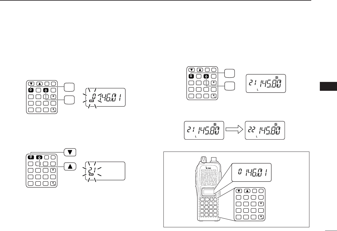
■Memory bank selection
The IC-V82 has a total of 10 banks (A to J). Regular memory
channels, 0 to 199, are assigned into the desired bank for
easy memory management.
qPush [C•
MR
]to select memory mode.
wPush [A•
FUNC
]and [#•
BANK
]to select memory bank con-
dition.
•Bank initial blinks.
eRotate [VOL] to select the desired bank, A to J.
•Banks that have no programmed contents are skipped.
rPush [✱•
ENT
](or [D•
CLR
]) to set the bank.
•Initial stops blinking.
tPush [YY]or [ZZ]to select the contents in the bank.
•No channel numbers are displayed for memory bank operation.
yTo return to regular memory condition, push [A•
FUNC
]and
[#•
BANK
]to enter memory bank condition, then push
[✱•
ENT
](or [D•
CLR
]).
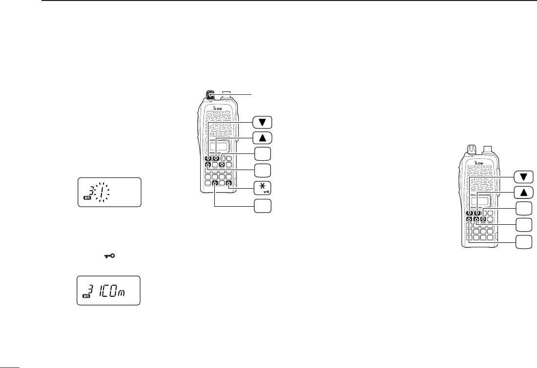
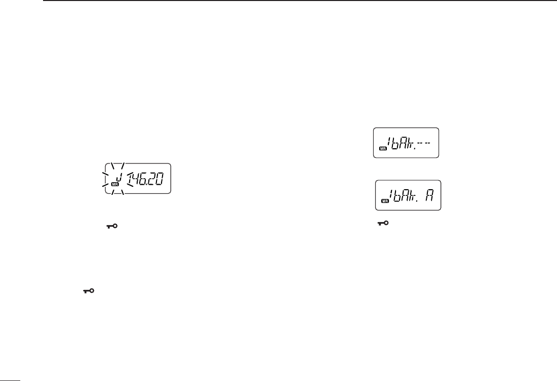
■Memory bank setting
qPush [C•
MR
]to select memory mode, then select the de-
sired memory channel via [YY]or [ZZ].
wPush [A•
FUNC
]and [8•
SET
]to enter
SET MODE
.
ePush [YY]or [ZZ]several times until “bAk” appears.
•“– –” indication blinks as follows.
rRotate [VOL] to select the desired bank to be set.
tPush [✱•
ENT
](or [D•
CLR
]) to set the channel into the
bank and return to regular memory condition.
yRepeat steps qto tto set another memory channel into
the same or another bank.

25
6
MEMORY/CALL OPERATION
6
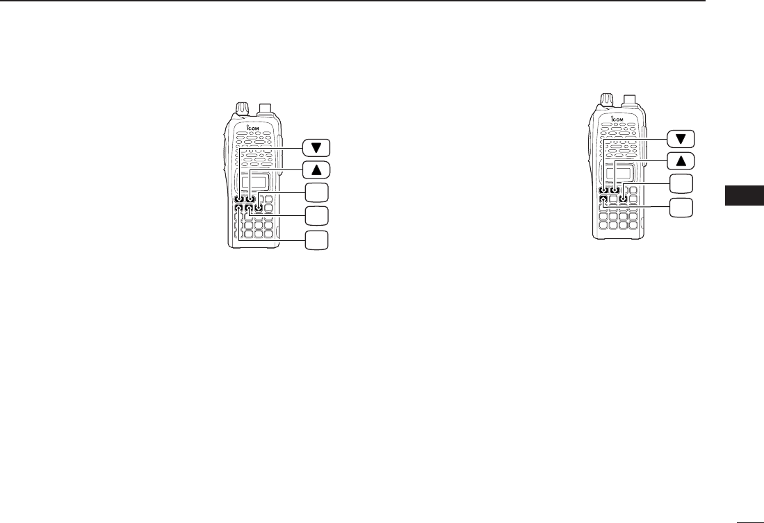
■Transferring bank contents
Contents of programmed memory banks can be cleared or
transferred to another bank.
INFORMATION: Even if the memory bank contents are
cleared, the memory channel contents still remain pro-
grammed.
q
Select the desired bank contents to be transferred or erased.
➥Push [C•
MR
]to select memory mode.
➥Push [A•
FUNC
]and [#•
BANK
], then rotate [VOL] to se-
lect the desired memory bank.
•Bank initial blinks.
➥Push [✱•
ENT
](or [D•
CLR
]) to select the bank then
push [YY]and [ZZ]to select the desired contents.
•Bank initial stops blinking.
wPush [A•
FUNC
]and [8•
SET
]to enter
SET MODE
.
ePush [YY]or [ZZ]several times until “bAk” appears.
•Bank initial appears.
rRotate [VOL] to select the desired bank initial to transfer or
erase.
•Select “– –” indication when erasing the contents from the bank.
tPush [✱•
ENT
](or [D•
CLR
]) to transfer or erase, and re-
turn to regular memory condition.
yRepeat steps qto tfor transferring or erasing an an-
other banks contents.
26
DTMF MEMORY
7
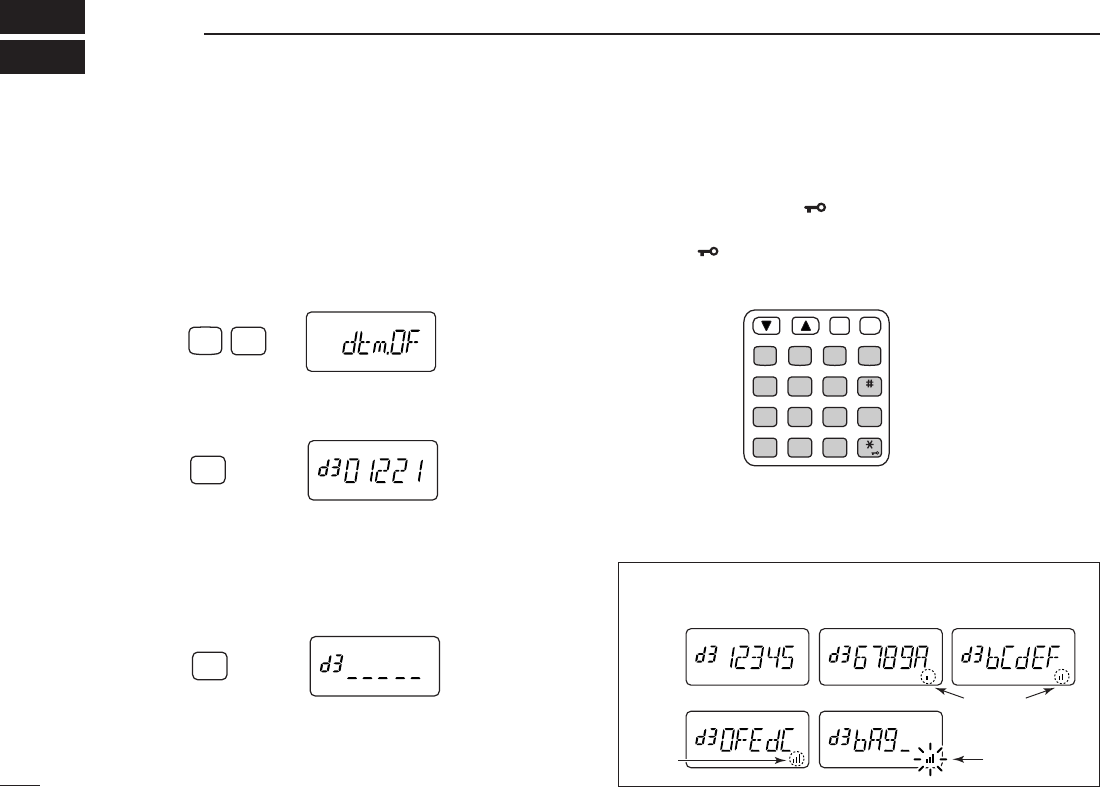
■Programming a DTMF code
The transceiver has 16 DTMF memory channels (d0 to dF)
for storage of often-used DTMF codes of up to 24 digits.
qPush [A•
FUNC
], then push [0•
OPT
]to enter
OPTION SET
MODE
.
•Rotate [VOL] to select “dtm.OF,” if necessary.
wPush [0•
OPT
]for 1 sec. to enter the DTMF memory.
•One of “d0” to “dF” appears.
e
Rotate [VOL] to select the desired channel.
rPush [0•
OPT
]for 1 sec. to enter the DTMF programming
mode.
•“_____” appears.
•Programmed memories can be cleared in this way.
tPush the digit keys, [A•
FUNC
], [B•
CALL
], [C•
MR
], [D•
CLR
],
[#•
BANK
]and [✱•
ENT
]to enter the desired DTMF code.
•Amaximum of 24 digits can be input.
•[✱•
ENT
]enters as “E”, [#•
BANK
]enters as “F.”
•If a digit is mistakenly input, push [MONI] or [PTT] momentarily
then repeat from step q.
yPush [MONI] or [PTT] to fix the digits and exit the DTMF
programming mode.
•Programmed DTMF codes sound when [MONI] is pushed.
MONI
CALL
DUP SCAN
PRIO
ENT
SET
H/M/L
OPTSKIP
BANK
TONE
T.SCANP.BEEP
MR CLRFUNC
PWR
987
4
123
AB DC
560
OPT
0
Push for 1 sec.
OPT
0
Push for 1 sec.
FUNC
A
OPT
0
Push
The DTMF memory consists of 5 pages that are 1st to 5th, 6 to
10th, 11 to 15th, 16 to 20th and 21st to 24th digits.
1st page indication
4th page indication 5th page indication
2nd page indication 3rd page indication
Appears
Appears Blinks

27
7
DTMF MEMORY
7
■Transmitting a DTMF code
DUsing a DTMF memory channel
qPush [A•
FUNC
], then push [0•
OPT
]to enter
OPTION SET
MODE
.
•Rotate [VOL] to select “dtm.OF,” if necessary.
wPush [0•
OPT
]for 1 sec. to enter the DTMF memory.
eRotate [VOL] to select the desired channel.
rPush [MONI] or [PTT] to exit the DTMF memory mode.
tWhile pushing [PTT], push [MONI] to transmit the selected
DTMF memory.
•After the DTMF code is transmitted, the transceiver returns to re-
ceive automatically.
DManual DTMF code transmission
While pushing [PTT], push digit keys, [A•
FUNC
], [B•
CALL
],
[C•
MR
], [D•
CLR
], [#•
BANK
]and [✱•
ENT
]to transmit a DTMF
code manually.
•[✱•
ENT
]enters as “E”, [#•
BANK
]enters as “F.”
■DTMF transmission speed
When slow DTMF transmission speeds are required with
DTMF memory transmission (as for some repeaters), the
transceiver’s rate of DTMF transmission can be adjusted.
qWhile pushing [YY]and [ZZ], turn the power on to enter
INI
-
TIAL SET MODE
.
wPush [YY]or [ZZ]several times until “dtd” appears.
eRotate [VOL] to select the desired DTMF transmission
speed.
•Four speeds are available: “1” (100 msec. intervals) is the fastest;
“5” (500 msec. intervals) is the slowest.
rPush [✱•
ENT
]to exit
INITIAL SET MODE
.
USING
INITIAL SET MODE
28
SCAN OPERATION
8
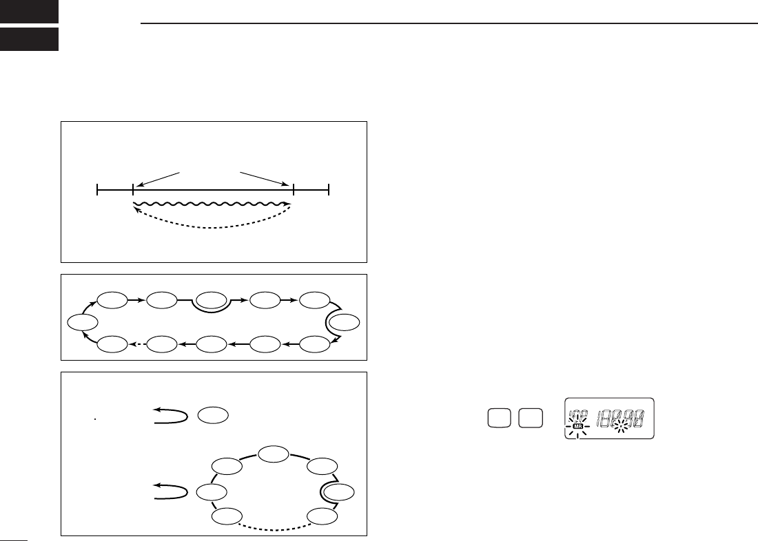
■Programmed scan
Programmed scan repeatedly scans between two user pro-
grammed frequencies (memory channels “1A–3A” and
“1b–3b”) or scans between upper and lower band edges. This
scan is useful for checking for signals within a specific fre-
quency range such as repeater output frequencies, etc.
Scans between lower (start) and high (stop) frequency.
qPush [D•
CLR
]to select VFO mode, if necessary.
wPush [A•
FUNC
]and [5•
SCAN
]to start the scan, then a se-
lected scan edge appears as “P1,” “P2,” “P3” or “AL.”
•To change the scan edge, push [A•
FUNC
]and [8•
SET
]several
times until the desired scan edge appears.
• “AL” for full scan, “P1”, “P2” and “P3” for programmed scan be-
tween the programmed scan edge channels as “1A”–“1b,”
“2A”–“2b” and “3A”–“3b.”
•To change the scan direction, push [YY]or [ZZ].
• When [VOL] is assigned as tuning dial, rotate [VOL] to change
the scan direction. (pgs. 14, 63)
ePush [D•
CLR
]to stop the scan.
Push
SCAN
FUNC
A
5
PROGRAMMED SCAN
MEMORY (SKIP) SCAN
PRIORITY WATCH
Band
edge
Band
edge
Start
1A
2A
3A
End
1b
2b
3b
Scan edges
Scan
Jump
SKIP SKIP
SKIP
Mch 1
Mch 0
Mch 2 Mch 3
Mch 3
Mch 4 Mch 5
Mch 10
Mch 199
Mch 9 Mch 8 Mch 7
Mch 6
Mch 1
Mch 2
Mch 3
Mch 4
Mch 5
Mch 199
Mch 6
VFO frequency
145.20 MHz
VFO frequency
145.20 MHz
5 sec. 50 msec.
5 sec. 50 msec.
Priority channel
Priority channel
Memory
scan
Priority memory channel watch
Priority memory channel scan
Programmed scan P1 scans between 1A and 1b, P2 scans be-
tween 2A and 2b, and P3 scans between 3A and 3b frequencies.
■Scan types
29
8
SCAN OPERATION
8
NOTE: Scan edges, 1A–3A/1b–3b, must be programmed
in advance. Program them in the same manner as regular
memory channels. (p. 21)
If the same frequencies are programmed into the scan
edges, programmed scan will not proceed.
■Memory scan
Memory scan repeatedly scans all programmed memory
channels, except those set as skip channels.
qPush [C•
MR
]to select memory mode, if necessary.
•“
X” appears.
wPush [A•
FUNC
]and [5•
SCAN
]to start the scan.
•To change the scan direction, push [YY]or [ZZ].
• When [VOL] is assigned as tuning dial, rotate [VOL] to change
the scan direction. (pgs. 14, 63)
ePush [D•
CLR
]to stop the scan.
• Bank scan —Select the desired bank at above step q.
qPush [A•
FUNC
]and [#•
BANK
]to select memory bank con-
dition.
wRotate [VOL] to select the desired bank, A to J.
ePush [✱•
ENT
](or [D•
CLR
]) to set the bank.
Push
SCAN
FUNC
A
5
MONI
CALL
DUP SCAN
PRIO
ENT
SET
H/M/L
OPTSKIP
BANK
TONE
T.SCANP.BEEP
MR CLRFUNC
PWR
987
4
123
AB DC
560

30
8SCAN OPERATION
■Skip channels
In order to speed up the scan interval, you can set memory
channels you don’t wish to scan as skip channels.
qPush [C•
MR
]to select memory mode, if necessary.
•“
X” appears.
wSelect a memory channel to set as a skip channel.
ePush [A•
FUNC
]and [6•
SKIP
]to toggle the skip setting ON
and OFF.
•“SKIP” appears when the channel is set as a skip channel.
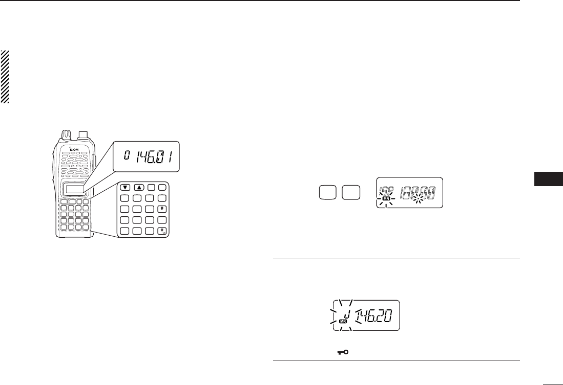
■Priority watch
Priority watch checks for signals on “priority channels” while
operating on a VFO frequency.
DMemory or call channel watch
While operating on a VFO frequency, memory or call channel
watch monitors for signals in the selected memory or call
channel every 5 sec.
qSelect the desired memory channel or the call channel.
wPush [D•
CLR
]to select VFO mode.
ePush [A•
FUNC
], then push [7•
PRIO
]to start watching.
•VFO is displayed, then the decimal point “.”, on the frequency
readout blinks.
•The priority channel is monitored every 5 sec.
• When the signal is detected on the priority channel, the watching
is paused according to the setting of the scan resume condition.
rPush [D•
CLR
]to stop watching.
Push
“SKIP” appears
SKIP
FUNC
A
6