ICOM orporated 284401 Scanning Receiver User Manual IC R9500 manual
ICOM Incorporated Scanning Receiver IC R9500 manual
Contents
- 1. User Manual 1
- 2. User Manual 2
- 3. User Manual 3
User Manual 1
COMMUNICATIONS RECEIVER
iR9500
Instruction Manual
A-6553H-1EX
Printed in Japan
© 2007 Icom Inc.
i
FOREWORD
Thank you for making the IC-R9500 your radio of choice. We hope you
agree with Icom’s philosophy of “technology first.” Many hours of research
and development went into the design of your IC-R9500.
D
FEATURES
❍Ultimate receiver performance: 110 dB wide dynamic range
and third-order intercept (IP3) of +40 dBm (HF bands only)
❍7-inch wide color TFT LCD
❍Built-in Baudot FSK demodulator
❍High resolution spectrum scope— center frequency and fix
frequency modes, plus mini-scope displays
IMPORTANT
READ THIS INSTRUCTION MANUAL CAREFULLY before at-
tempting to operate the receiver.
SAVE THIS INSTRUCTION MANUAL. This manual contains im-
portant safety and operating instructions for the IC-R9500.
EXPLICIT DEFINITIONS
TRADEMARKS
Icom, Icom Inc. and the logo are registered trademarks of Icom
Incorporated (Japan) in the United States, the United Kingdom, Germany,
France, Spain, Russia and/or other countries.
WORD DEFINITION
RWARNING Personal injury, fire hazard or electric shock may
occur.
CAUTION Equipment damage may occur.
NOTE If disregarded, inconvenience only. No risk of person-
al injury, fire or electric shock.

ii
PRECAUTIONS
RWARNING! NEVER operate the receiver with a
headset or other audio accessories at high volume
levels. Hearing experts advise against continuous high
volume operation. If you experience a ringing in your
ears, reduce the volume or discontinue use.
RCAUTION! NEVER change the internal set-
tings of the receiver. This may reduce receiver perfor-
mance and/or damage to the receiver.
The receiver warranty does not cover any problems
caused by unauthorized internal adjustment.
RCAUTION! The receiver weighs approx. 20 kg
(44 lb). Always have two people available to carry, lift
or turn over the receiver.
RCAUTION! The line-voltage receptacle must be
near the receiver and must be easily accessible. Avoid
extension cords.
RACHTUNG! Die Steckdose muß nabe bei
diesem Gerät angebracht und zugänglich sein.
RNEVER let metal, wire or other objects protrude
into the receiver or into connectors on the rear panel.
This may result in an electric shock.
RNEVER block any cooling vents on the top, rear
or bottom of the receiver.
RNEVER expose the receiver to rain, snow or any
liquids.
RNEVER install the receiver in a place without ad-
equate ventilation. Heat dissipation may be reduced,
and the receiver may be damaged.
RNEVER operate or touch the receiver with wet
hands. This may result in an electric shock or damage
to the receiver.
DO NOT
use chemical agents such as benzine or al-
cohol when cleaning the IC-R9500, as they can dam-
age the receiver’s surfaces.
AVOID using or storing the receiver in areas with tem-
peratures below ±0°C (+32°F) or above +50°C
(+122°F).
AVOID placing the receiver in excessively dusty envi-
ronments or in direct sunlight.
AVOID placing the receiver against walls or putting
anything on top of the receiver. This may overheat the
receiver.
Always place unit in a secure place to avoid inadver-
tent use by children.
The LCD display may have cosmetic imperfections that
appear as small dark or light spots. This is not a mal-
function or defect, but a normal characteristic of LCD
displays.
During maritime mobile operation, keep the receiver as
far away as possible from the magnetic navigation
compass to prevent erroneous indications.
Turn [I/O] switch (on the rear panel) OFF and/or dis-
connect the AC power cable from the AC outlet when
you will not use the receiver for a long period of time.
For U.S.A. only
CAUTION: Changes or modifications to this device,
not expressly approved by Icom Inc., could void your
authority to operate this device under FCC regulations.
ABOUT APCO PROJECT 25
This device made under license under one or more of
the following US patents: #4,590,473, #4,636,791,
#5,148,482, #5,185,796, #5,271,017, #5,377,229.
The IMBE™ voice coding technology embodied in this
product is protected by intellectual property rights
including patent rights, copyrights and trade secrets of
Digital Voice Systems, Inc. This voice coding
Technology is licensed solely for use within this com-
munications equipment. The user of this technology is
explicitly prohibited from attempting to decompile,
reverse engineer, or disassemble the object code, or
in any other way convert the object code into a
human-readable form. U.S. Pat. nos. #5,870,405,
#5,826,222, #5,754,974, #5,701,390, #5,715,365,
#5,649,050, #5,630,011, #5,581,656, #5,517,511,
#5,491,772, #5,247,579, #5,226,084, #5,195,166.
P25 digital mode is available when the optional
UT-122 DIGITAL UNIT is installed.
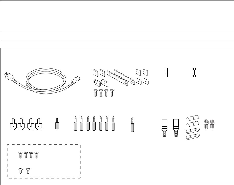
qAC power cable* ………………………………… 1
wCarrying handles ……………………………… 1 set
eSpare fuse (FGB 1 A) …………………………… 1
rSpare fuse
FGB 4 A (100 V/120 V versions) ………………… 1
0234002MXP (230 V/240 V versions)
…………… 1
tRCA plugs ………………………………………… 4
yDC power plug …………………………………… 1
u2-conductor 1⁄8wplugs …………………………… 7
i3-conductor 1⁄8wplugs …………………………… 1
o8 pin ACC plugs …………………………………… 2
!0 Screws for side plate†…………………………… 4
!1 Hiding screws for screw hole†…………………… 2
*May differ from that shown according to version
†These screw are used when removing rack mounting han-
dles
iii
SUPPLIED ACCESSORIES
q
o
!0
!1
tyu i
e
wr
(FH M4×16 mm)
(FH M4×12 mm)
(PH M4×8 mm) PH: Pan head
FH: Flat head

iv
Section 1 PANEL DESCRIPTION
■Front panel ……………………………………………………………… 1-2
■Rear panel ……………………………………………………………… 1-8
■LCD display …………………………………………………………… 1-10
■Screen menu arrangement …………………………………………… 1-12
Section 2 INSTALLATION AND CONNECTIONS
■Unpacking ……………………………………………………………… 2-2
■Selecting a location …………………………………………………… 2-2
■Grounding ……………………………………………………………… 2-2
■Antenna connection …………………………………………………… 2-3
■TV jumper cable connection …………………………………………… 2-4
■Carrying handle attachment …………………………………………… 2-4
■Rack mounting handle detachment …………………………………… 2-4
■Required connections ………………………………………………… 2-5
DRear panel …………………………………………………………… 2-5
■Advanced connections ………………………………………………… 2-6
DFront panel …………………………………………………………… 2-6
DRear panel—1 ……………………………………………………… 2-6
DRear panel—2 ……………………………………………………… 2-7
■Tape recorder connections …………………………………………… 2-8
DRecording from the front panel or rear panel …………………… 2-8
DSeparately recording audio and frequency ……………………… 2-9
■Monitor display connection …………………………………………… 2-10
■Transceive function …………………………………………………… 2-10
■FSK and AFSK (SSTV) connections ………………………………… 2-11
■Accessory connector information …………………………………… 2-12
Section 3 BASIC OPERATIONS
■When first applying power (CPU resetting) ………………………… 3-2
■Initial settings …………………………………………………………… 3-2
■Selecting VFO mode …………………………………………………… 3-3
■Selecting memory mode ……………………………………………… 3-3
■Frequency setting ……………………………………………………… 3-4
DDirect frequency entry with the keypad …………………………… 3-4
DTuning with the main dial …………………………………………… 3-5
DSelecting a tuning step ……………………………………………… 3-5
DAuto tuning step function …………………………………………… 3-6
D1⁄4tuning step function ……………………………………………… 3-6
■Operating mode selection ……………………………………………… 3-7
■Volume setting ………………………………………………………… 3-8
■RF gain adjustment …………………………………………………… 3-8
■Squelch level adjustment ……………………………………………… 3-8
■Audio tone adjustment ………………………………………………… 3-9
DTreble level adjustment ……………………………………………… 3-9
DBass level adjustment ……………………………………………… 3-9
■Meter indication selection …………………………………………… 3-10
DMeter type selection ……………………………………………… 3-10
Section 4 RECEIVE MODES
■Operating FM …………………………………………………………… 4-2
DConvenient functions for FM …………………………………………4-2
■Duplex operation ……………………………………………………… 4-3
DOffset frequency setting ………………………………………………4-3
TABLE OF CONTENTS

■Tone/DTCS squelch operation ………………………………………… 4-4
■Operating WFM ………………………………………………………… 4-5
DConvenient functions for WFM ………………………………………4-5
■TV channel operation ………………………………………………… 4-6
DConvenient functions for TV operation ……………………………4-6
■Operating AM …………………………………………………………… 4-7
DConvenient functions for AM …………………………………………4-7
■Operating SSB ………………………………………………………… 4-8
DConvenient functions for SSB ………………………………………4-8
■Operating CW …………………………………………………………… 4-9
DConvenient functions for CW ………………………………………4-9
DAPF (Audio Peak Filter) operation …………………………………4-10
DAbout CW reverse mode ……………………………………………4-10
DAbout CW pitch control ……………………………………………4-10
■Operating FSK ………………………………………………………… 4-11
DConvenient functions for FSK ………………………………………4-12
DAbout FSK reverse mode …………………………………………4-12
DTwin peak filter ………………………………………………………4-12
DFunctions for the FSK decoder indication …………………………4-13
DSetting the decoder threshold level ………………………………4-13
DFSK decode set mode ………………………………………………4-14
DTime stamp function …………………………………………………4-15
DSetting FSK tone frequency ………………………………………4-16
DSetting FSK Baud rate ………………………………………………4-16
DData saving …………………………………………………………4-17
■Operating P25 (Requires optional UT-122) ………………………… 4-18
DConvenient functions for P25 ………………………………………4-18
■Digital squelch operation ……………………………………………… 4-19
Section 5 RECEIVE FUNCTIONS
■Spectrum scope screen ……………………………………………… 5-2
DCenter mode ………………………………………………………… 5-2
DFix mode ……………………………………………………………… 5-3
DPeak marker function ……………………………………………… 5-4
DWide band-pass filter selection……………………………………… 5-5
DWide band scope function …………………………………………… 5-5
DMini scope screen indication ……………………………………… 5-6
DScope set mode ……………………………………………………… 5-6
■Preamplifier ……………………………………………………………… 5-9
■Attenuator ……………………………………………………………… 5-9
■AGC function …………………………………………………………… 5-10
DSelecting the preset value …………………………………………5-10
DAdjusting the AGC time constant …………………………………5-10
DSetting the AGC time constant preset value ……………………5-10
■Twin PBT operation …………………………………………………… 5-11
■IF filter selection ……………………………………………………… 5-12
DIF filter selection …………………………………………………… 5-12
DFilter passband width setting ……………………………………… 5-12
DRoofing filter selection ……………………………………………… 5-13
DDSP filter shape …………………………………………………… 5-13
DFilter shape set mode ……………………………………………… 5-13
■Noise blanker ………………………………………………………… 5-15
DNB set mode ………………………………………………………… 5-15
v
TABLE OF CONTENTS

vi
■Noise reduction ………………………………………………………… 5-16
■Notch function ………………………………………………………… 5-16
■Autotune function ……………………………………………………… 5-17
■AFC function …………………………………………………………… 5-17
Section 6 VOICE RECORDER FUNCTIONS
■About digital voice recorder …………………………………………… 6-2
■Recording a received audio …………………………………………… 6-3
DRegular recording …………………………………………………… 6-3
■Playing the recorded audio …………………………………………… 6-3
DRegular playing ……………………………………………………… 6-3
■Erasing the recorded contents ………………………………………… 6-4
■Selecting the CF memory card or USB-Memory …………………… 6-4
■Short recording ………………………………………………………… 6-5
DRecording …………………………………………………………… 6-5
DPlaying back ………………………………………………………… 6-5
■Voice set mode ………………………………………………………… 6-6
Section 7 MEMORY OPERATION
■Memory channels ……………………………………………………… 7-2
■Memory channel selection …………………………………………… 7-3
DUsing the [M-CH]/[BANK] selectors ……………………………… 7-3
DUsing the keypad …………………………………………………… 7-3
■Memory channel programming ……………………………………… 7-4
DProgramming in VFO mode ………………………………………… 7-4
DProgramming in memory mode …………………………………… 7-4
■Frequency transferring ………………………………………………… 7-5
DTransferring in VFO mode ………………………………………… 7-5
DTransferring in memory mode ……………………………………… 7-5
■Memory names ………………………………………………………… 7-6
DEditing (programming) memory names …………………………… 7-6
■Memory clearing ………………………………………………………… 7-6
■Memory list screen ……………………………………………………… 7-7
DSelecting a memory channel using the memory list screen …… 7-7
DConfirming programmed memory channels ……………………… 7-7
DMemory bank set …………………………………………………… 7-8
Section 8 SCANS
■Scan types ……………………………………………………………… 8-2
■Preparation ……………………………………………………………… 8-3
■Voice squelch control function ………………………………………… 8-3
■Scan set mode ………………………………………………………… 8-4
■Priority scan ……………………………………………………………… 8-5
DSetting ………………………………………………………………… 8-5
DPriority scan operation ……………………………………………… 8-5
■Programmed scan ……………………………………………………… 8-6
DSetting ………………………………………………………………… 8-6
DProgram scan operation …………………………………………… 8-7
■∂F scan ………………………………………………………………… 8-8
DSetting ………………………………………………………………… 8-8
D∂F scan operation …………………………………………………… 8-8
■Fine programmed scan/fine ∂F scan operation……………………… 8-9
■Auto memory write scan operation…………………………………… 8-10
TABLE OF CONTENTS

■Memory scan …………………………………………………………… 8-11
DSetting ……………………………………………………………… 8-11
DMemory scan operation …………………………………………… 8-11
DProgramming the select memory scan setting ………………… 8-12
DSelect memory scan operation …………………………………… 8-13
DMode select memory scan operation …………………………… 8-14
■Skip scan ……………………………………………………………… 8-15
DSpecifying skip channels ………………………………………… 8-15
DProgramming skip frequencies (for programming scan) ……… 8-15
DSkip scan setting …………………………………………………… 8-15
■Tone scan ……………………………………………………………… 8-16
■Scan resume condition………………………………………………… 8-17
■Scan speed …………………………………………………………… 8-18
■Scan delay ……………………………………………………………… 8-18
Section 9 OTHER FUNCTIONS
■Voice synthesizer operation …………………………………………… 9-2
■Lock function …………………………………………………………… 9-2
DDial lock function ……………………………………………………… 9-2
DPanel lock function …………………………………………………… 9-2
■Dial click function ……………………………………………………… 9-3
■Antenna selection ……………………………………………………… 9-3
Section 10 CLOCK AND TIMERS
■Time set mode ………………………………………………………… 10-2
■Daily timer setting …………………………………………………… 10-3
■Setting sleep timer …………………………………………………… 10-4
■Timer operation ………………………………………………………… 10-4
Section 11 SET MODE
■Set mode description ………………………………………………… 11-2
DSet mode operation ………………………………………………… 11-2
DScreen arrangement ……………………………………………… 11-3
■Level set mode ………………………………………………………… 11-4
■ACC set mode ………………………………………………………… 11-7
■Display set mode ……………………………………………………… 11-8
■Others set mode ……………………………………………………… 11-10
■CF card/USB-Memory set menu …………………………………… 11-16
DCF/USB-Memory set screen arrangement …………………… 11-16
DLoad option set mode …………………………………………… 11-17
■File saving …………………………………………………………… 11-18
■File loading …………………………………………………………… 11-19
■Changing the file name ……………………………………………… 11-20
■File copying …………………………………………………………… 11-21
■Deleting a file ………………………………………………………… 11-22
■Unmount an USB-Memory ………………………………………… 11-22
■Formatting the CF card or USB-Memory ………………………… 11-23
■Display set (Video) mode …………………………………………… 11-24
■LCD set mode ………………………………………………………… 11-26
Section 12 MAINTENANCE
■Troubleshooting ……………………………………………………… 12-2
DReceiver power …………………………………………………… 12-2
DReceiving …………………………………………………………… 12-2
vii
TABLE OF CONTENTS

viii
DScanning …………………………………………………………… 12-3
DDisplay ……………………………………………………………… 12-3
DVoice recorder ……………………………………………………… 12-3
DFormat memory media …………………………………………… 12-3
■Screen type selection ………………………………………………… 12-4
■Main dial brake adjustment ………………………………………… 12-4
■Frequency calibration (approximate) ……………………………… 12-5
■Opening the receiver’s case ………………………………………… 12-6
■Opening the shield case ……………………………………………… 12-6
■UT-122 installation …………………………………………………… 12-7
■Clock backup battery replacement ………………………………… 12-7
■Fuse replacement …………………………………………………… 12-8
DAC power input fuse ……………………………………………… 12-8
DDC output fuse ……………………………………………………… 12-8
■Resetting the CPU …………………………………………………… 12-9
■Screen Saver Function ……………………………………………… 12-9
Section 13 CONTROL COMMAND
■Remote interface (CI-V) information ………………………………… 13-2
DCI-V connection example ………………………………………… 13-2
DData format ………………………………………………………… 13-2
DCommand table …………………………………………………… 13-3
DTo send/read memory contents ………………………………… 13-10
DCodes for memory name, bank name, opening message,
and clock 2 name contents ……………………………………… 13-10
DOffset frequency setting ………………………………………… 13-10
DTone squelch frequency setting ………………………………… 13-10
DDTCS squelch code setting ……………………………………… 13-10
DNAC squelch code setting ……………………………………… 13-11
DSelective squelch code settings ………………………………… 13-11
DColor setting ……………………………………………………… 13-11
DData mode with filter width setting ……………………………… 13-11
Section 14 SPECIFICATIONS AND OPTIONS
■Specifications ………………………………………………………… 14-2
DGeneral ……………………………………………………………… 14-2
DReceiver …………………………………………………………… 14-3
■Options ………………………………………………………………… 14-4
Section 15 UPDATING THE FIRMWARE
■General ………………………………………………………………… 15-2
■Caution ………………………………………………………………… 15-2
■Preparation …………………………………………………………… 15-3
DFirmware and firm utility …………………………………………… 15-3
DFile downloading …………………………………………………… 15-3
■Firmware update— CF memory card ……………………………… 15-4
■Firmware update— PC ……………………………………………… 15-6
DConnections ………………………………………………………… 15-6
DIP address setting ………………………………………………… 15-7
DUpdating from the PC ……………………………………………… 15-8
TABLE OF CONTENTS

1-1
PANEL DESCRIPTION Section 1
■Front panel ……………………………………………………………… 1-2
■Rear panel ……………………………………………………………… 1-8
■LCD display …………………………………………………………… 1-10
■Screen menu arrangement …………………………………………… 1-12
1-2
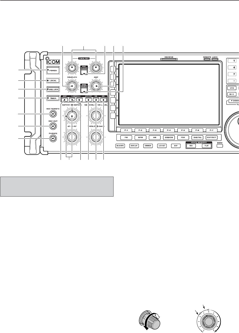
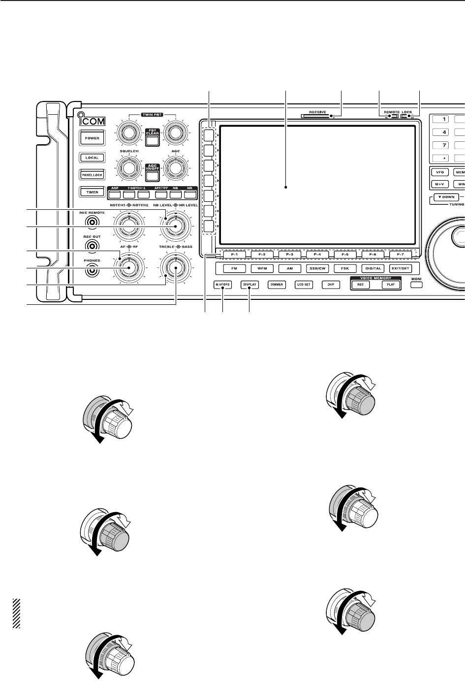
■Front panel
qPOWER SWITCH [POWER] (p. 3-2)
➥Push to turn the receiver power ON.
• The [POWER] indicator above this switch lights green
when powered ON.
➥Push for 1 sec. to turn the receiver power OFF.
• The [POWER] indicator lights orange when the re-
ceiver is OFF when the internal power supply is
switched ON.
wREMOTE CONTROL SWITCH [LOCAL]
Push to cancel remote control operation from a PC
via a CI-V data.
• The [REMOTE] indicator lights yellow while in remote
control operation.
• When the [REMOTE] indicator lights yellow, all dials,
keys or switches other than this switch are disabled.
ePANEL LOCK SWITCH [PANEL LOCK] (p. 9-2)
Push to turn the panel lock function ON or OFF. The
panel lock function locks all dials, keys and switches
other than [POWER] and [PANEL LOCK].
• The [PANEL LOCK] indicator above this switch lights
yellow when the timer is in use.
• The dial lock function is also available.
rTIMER SWITCH [TIMER] (p. 10-3)
➥Turns the sleep or daily timer function ON or
OFF.
• The [TIMER] indicator above this switch lights green
when the timer is in use.
➥Enters timer set mode when pushed and held for
1sec.
tRECORDER REMOTE JACK [REC REMOTE]
Controls the operation of a tape recorder for record-
ing. Connects to the REMOTE jack on a tape
recorder.
yRECORDER JACK [REC OUT]
Outputs an audio signal. Connect to the AUX or
LINE IN jack on a tape recorder.
uHEADPHONE JACK [PHONES]
Accepts standard 3.5 (d) mm (1⁄8) stereo head-
phones.
• Output power: 40 mW with an 8 load.
• When headphones are connected, the internal speaker
or connected external speaker does not function.
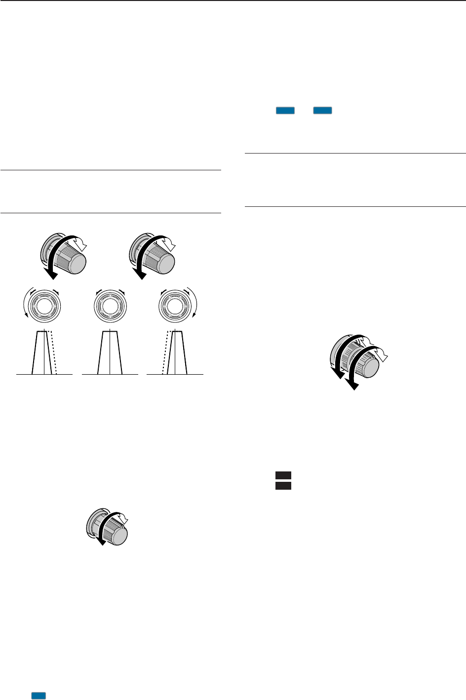
iSQUELCH CONTROL [SQUELCH] (p. 3-8)
Adjusts the squelch threshold level. The squelch
disables output from the speaker (closed condition)
when no signal is received.
• The squelch control is particularly effective for FM or
AM. It is also available for other modes.
• 11 to 12 o’clock position is recommended for any set-
ting of the [SQL] control.
Deep
Deep
S-meter
squelch
Noise squelch
Squelch
is open.
Squelch
threshold
Shallow Shallow
Turn the internal power supply ON before turning the
unit ON from the front panel. The internal power sup-
ply switch is located on the rear panel. (p. 3-2)
1PANEL DESCRIPTION
i!0
q
w
e
r
t
y
u
o!1 !2
!3 !4 !5 !8
!6 !7
1-3
oPASSBAND TUNING CONTROLS [TWIN PBT]
(p. 5-11)
Adjusts the IF filter “passband width” via the DSP.
• Passband width and shift frequency are shown on the
multifunction display.
• Push and hold [PBT CLEAR] for 1 sec. to clear the PBT
settings.
• Variable range is set to half of the IF filter passband
width. 25 Hz steps and 50 Hz steps are available in
SSB, CW and FSK modes.
✔
What is the PBT control?
The PBT function electronically modifies the IF passband
width to reject interference. This receiver uses the DSP cir-
cuit for the PBT function.
!0 PBT CLEAR SWITCH [PBT CLEAR] (p. 5-11)
Push and hold for 1 sec. to clear the PBT settings.
• The [PBT CLEAR] indicator above this switch lights
when PBT is in use.
!1 AGC CONTROL [AGC] (p. 5-10)
Adjusts the continuously-variable AGC circuit time
constant.
• To use [AGC] control, push the appropriate band’s
[AGC VR/OFF] ([AGC VR] indicator lights green).
!2 AGC SWITCH [AGC VR/OFF] (p. 5-10)
➥Push to toggle [AGC] control usage ON or OFF.
• Use [AGC] control to set the AGC time constant when
switched ON.
• The [AGC VR] indicator above this switch lights
green when the control is ON.
➥Turns the AGC function OFF when pushed and
held for 1 sec.
!3 AUTO NOTCH SWITCH [ANF] (p. 5-16)
➥Turns the auto notch function ON or OFF when
pushed in SSB, AM, FM and WFM mode.
• “ ” appears when auto notch is in use.
!4 MANUAL NOTCH SWITCHES
[NOTCH1]/[NOTCH2] (p. 5-16)
➥Turns the manual notch function ON or OFF
when pushed in SSB, CW, AM and FSK mode.
• “ ” or “ ” appear when manual notch is in use.
➥Switches the manual notch characteristics be-
tween wide, middle and narrow when pushed
and held for 1 sec.
✔
What is the notch function?
The notch function eliminates unwanted CW or AM carrier
tones while preserving the desired voice signal. The DSP cir-
cuit automatically adjusts the notch frequency to effectively
eliminate unwanted tones.
!5 MANUAL NOTCH FILTER CONTROLS
[NOTCH1]/[NOTCH2] (p. 5-16)
Varies the “notch” frequency of the manual notch fil-
ter to reject an interfering signal while the manual
notch function is ON.
• Notch filter center frequency:
SSB : –1060 Hz to 4040 Hz
CW : CW pitch freq. + 2540 Hz to CW pitch freq.
–2540 Hz
AM : –5100 Hz to 5100 Hz
!6 AUDIO PEAK FILTER/TWIN PEAK FILTER
SWITCH [APF/TPF]
➥Push to turn the audio peak filter ON or OFF dur-
ing CW mode operation. (p. 4-10)
➥Push to turn the twin peak filter ON or OFF dur-
ing FSK mode operation. (p. 4-12)
• “ ” appears when audio peak filter is in use.
• “ ” appears when twin peak filter is in use.
➥During CW mode operation, push and hold for
1 sec. to select the APF passband width from 80,
160 and 320 Hz. (p. 4-10)
!7 NOISE BLANKER SWITCH [NB] (p. 5-15)
➥Selects from noise blanker 1, 2, or OFF when
pushed. The noise blanker reduces pulse-type
noise such as that generated by automobile igni-
tion systems. This function cannot be used for
FM/WFM, P25 modes or non-pulse-type noise.
• The [NB] indicator above this switch lights green and
“NB1” or “NB2” appears on the display when the
function is activated.
➥Enters blank-width set mode when pushed and
held for 1 sec.
!8 NOISE REDUCTION SWITCH [NR] (p. 5-16)
Push to switch the DSP noise reduction ON or OFF.
• The [NR] indicator above this switch lights green when
the function is activated.
TPF
APF
Higher
frequency
NOTCH1
NOTCH2
Lower
frequency
MN2
MN1
AN
Slow
Fast
Low cutHigh cut Center
–+
(PBT1) (PBT2)
1
PANEL DESCRIPTION
1-4
■Front panel (continued)
!9 NOISE REDUCTION LEVEL CONTROL
[NR LEVEL] (outer control; p. 5-16)
Adjusts the DSP noise reduction level when noise
reduction is in use. Set for maximum readability.
• To use this control, noise reduction must be ON.
@0 NOISE BLANKER CONTROL [NB LEVEL]
(inner control; p. 5-15)
Adjust the noise blanker threshold level.
• To use this control, either noise blanker must be ON.
@1 RF GAIN CONTROL [RF] (outer control; p. 3-8)
Adjusts the RF gain level.
While rotating the RF gain control, you may hear
noise. This comes from the DSP unit and does
not indicate a malfunction.
@2 AF CONTROL [AF] (inner control; p. 3-8)
Varies the audio output level of the speaker or
headphones.
@3 BASS RESPONSE CONTROL [BASS]
(outer control; p. 3-9)
Adjusts the bass response of the audio output.
@4 TREBLE RESPONSE CONTROL [TREBLE]
(inner control; p. 3-9)
Adjusts the treble response of the audio output.
Treble level
increases
Treble level
decreases
Bass level
increases
Bass level
decreases
Audio output
increases
Audio output
decreases
Sensitivity
increases
Sensitivity
decreases
Deep
Shallow
Increases
Decreases
1PANEL DESCRIPTION
@7@6 @8 @9
#0
!9
@1
@2
@0
@3
@4
@5
#1 #2
1-5
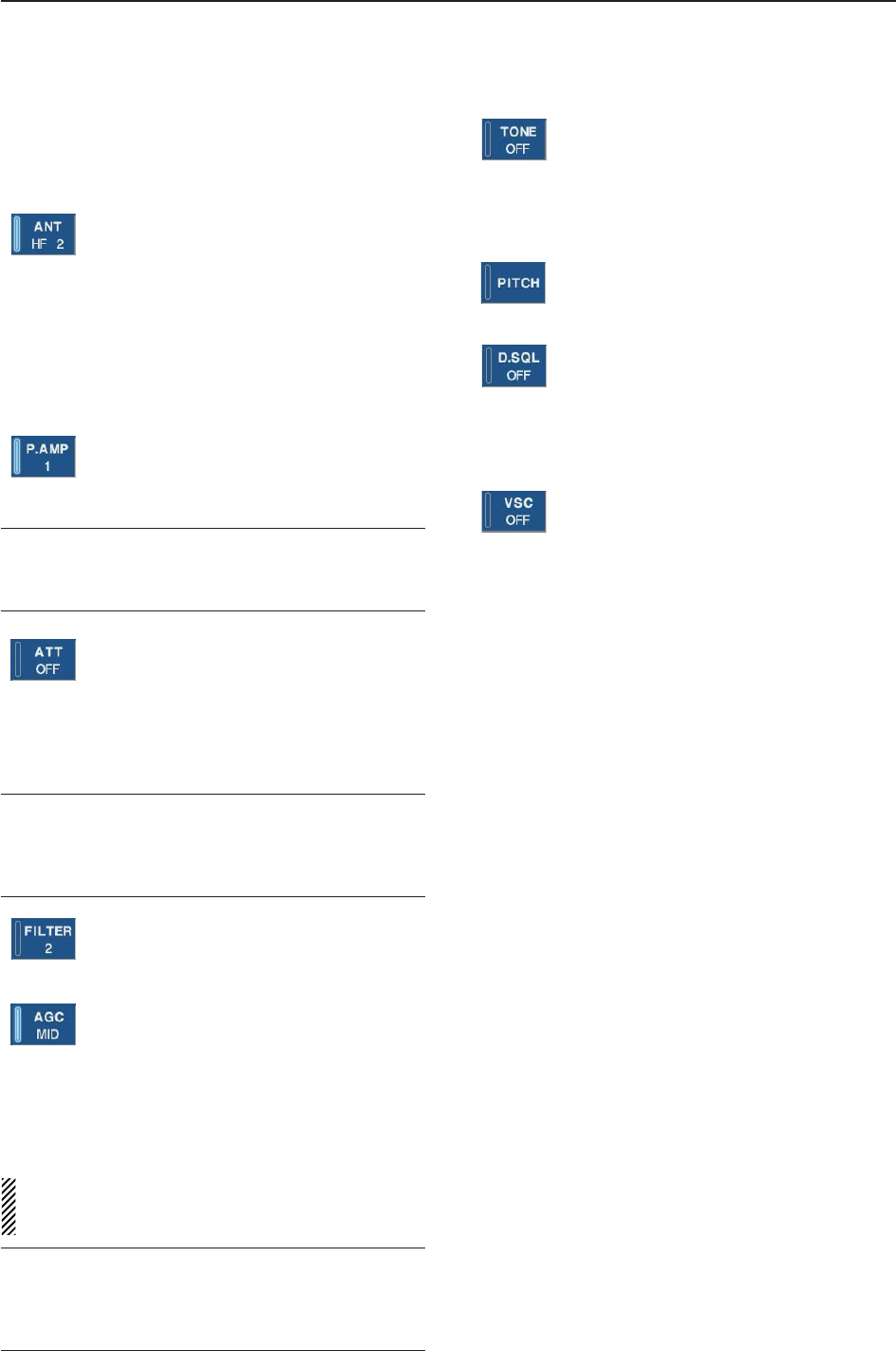
@5 MULTIFUNCTION SWITCHES
Push to select the functions indicated in the LCD
display to the right of these switches.
• Functions vary depending on the operating condition.
➥
While operating HF bands, selects the an-
tenna connector from HF ANT 1, HF ANT
2 and HF ANT 3 when pushed. (p. 9-3)
• During 30–1150 MHz operation, only ANT 1
is available.
• During 1150–3335 MHz operation, only ANT
2 is available.
➥
Turns the antenna control voltage ON and
OFF form [ANT SEL] when pushed and
held for 1 sec. (p. 9-3)
➥Selects one of 2 receive RF preamps or
bypasses them. (p. 5-9)
• “P. AMP1” activates 10 dB preamp.
•
“P. AMP2” activates 16 dB high-gain preamp.
✔
What is the preamp?
The preamp amplifies received signals in the front end cir-
cuit to improve S/N ratio and sensitivity. Select “P. AMP1” or
“P. AMP2” when receiving weak signals.
➥Selects the attenuator when pushed.
(p. 5-9)
• HF bands: 6, 12, 18, 24, 30 dB.
• 30–1150 MHz,: 10, 20, 30 dB.
• 1150–3335 MHz: 20 dB only.
➥Turns OFF the attenuator when pushed
and held for 1 sec. (p. 5-9)
✔
What is the attenuator?
The attenuator prevents a desired signal from distorting
when very strong signals are near the receiving frequency,
or when very strong electric fields, such as from a broad-
casting station, are near your location.
➥Selects one of 3 IF filter settings.
➥Enters the filter set screen when pushed
and held for 1 sec.
➥
Activates and selects fast, middle or slow
AGC time constant when pushed. (p. 5-10)
• In FM/WFM or P25 mode, only “FAST” is
available.
• “VR (volume)” indicates that AGC time con-
stant depends on [AGC] control.
➥Enters the AGC set mode when pushed
and held for 1 sec. (p. 5-10)
AGC time constant can be set from 0.1 to 8.0 sec.
(depends on mode), or turned OFF. When AGC is
“OFF,” the S-meter does not function.
✔
What is the AGC?
The AGC controls receiver gain to produce a constant audio
output level, even when the received signal strength varies
dramatically. Select “FAST” for tuning and then select “MID”
or “SLOW” depending on the receiving conditions.
➥
Switches between the tone squelch,
DTCS squelch function and no-tone oper-
ation when pushed in FM mode. (p. 4-4)
➥Enters the tone set mode when pushed
and held for 1 sec. in FM/FSK mode.
(pgs. 4-4, 4-16)
➥
Push to toggle the CW pitch setting
screen ON and OFF in CW mode.
(p.4-10)
(Requires optional UT-122)
➥
Switches the digital squelch between
NAC squelch, selective squelch and OFF
in P25 mode. (p. 4-19)
➥
Enters the code set mode when pushed
and held for 1 sec. in P25 mode. (p. 4-19)
➥Push to switch the voice squelch control
function ON and OFF; useful for scan-
ning.
@6 LCD FUNCTION DISPLAY (p. 1-10)
Shows the operating frequency, function switch
menus, spectrum scope screen, memory channel
screen, set mode settings, etc.
@7 RECEIVE INDICATOR [RECEIVE]
Lights green while receiving a signal and when the
squelch is open.
@8 REMOTE CONTROL INDICATOR [REMOTE]
Lights yellow when a command is received from a
PC via CI-V data.
• When this indicator lights yellow, all dials, keys or
switches other than [LOCAL] are disabled.
• This indicator goes OFF, when [LOCAL] is pushed.
@9 DIAL LOCK INDICATOR [LOCK] (p. 9-2)
Lights orange when the dial lock function is acti-
vated.
#0 LCD FUNCTION SWITCHES [F-1]–[F-7]
Push to select the function indicated in the LCD dis-
play above these switches.
• Functions vary depending on the operating condition.
#1 MINI SPECTRUM SCOPE SWITCH [M.SCOPE]
(p. 5-6)
Turns the mini spectrum scope screen ON or OFF.
• The mini spectrum scope screen can be displayed with
another screen, such as memory or set mode screen,
simultaneously.
#2 DISPLAY SWITCH [DISPLAY]
➥Push to toggle the external input screen between
mini TV screen, full TV screen, or OFF.
• If no signal inputs from [VIDEO IN], black screen ap-
pears.
➥Enter the display set mode menu screen when
pushed and held for 1 sec.
1
PANEL DESCRIPTION
1-6
■Front panel (continued)
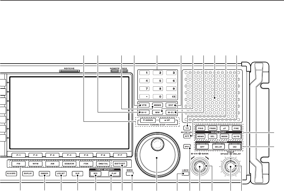
#3 TUNING STEP SWITCHES [▲UP]/[▼DOWM]
(p. 3-5)
➥Select the tuning step for the main dial. Push
[▲UP] to select a larger tuning step; push
[▼DOWN] to select a smaller tuning step.
• 1 Hz, 10 Hz, 100 Hz, 1 kHz, 2.5 kHz, 5 kHz, 6.25
kHz, 9 kHz, 10 kHz, 12.5 kHz, 20 kHz, 25 kHz, 100
kHz and 1 MHz are selectable.
• Programmable tuning steps can be set between 0.1
and 999.9 kHz in 0.1 kHz steps.
➠To set programmable tuning steps, enter the de-
sired steps via the keypad, then push [YUP] or
[ZDOWN].
➥Push and hold [▲UP] (or [▼DOWN]) for 1 sec.
to enter the tuning step select screen.
• Unwanted tuning step for each operating mode can
be skipped in the tuning step select.
#4 MEMORY TRANSFER SWITCH [M≈V] (p. 7-5)
Transfers the memory contents to VFO when
pushed and held for 1 sec.
• This function is available both in VFO and memory
modes.
#5 MEMORY SWITCH [MEMO] (p.7-3)
➥Selects the memory mode when pushed.
• After pushing one to three digit (0 to 999), pushing
the switch selects a memory channel.
➥Memory bank limit function ON or OFF when
pushed and held for 1 sec.
#6 VFO SWITCH [VFO]
Selects the VFO mode when pushed. (p. 3-3)
• After pushing a digit switch (0 to 9), push this switch se-
lects a VFO mode (VFO-0 to VFO-9).
#7 KEYPAD (pgs. 3-3, 3-4, 7-3)
Enters a frequency or memory channel. Pushing
[ENT], [VFO] or [MEMO] ends keypad input.
• e.g. to enter 14.195 MHz, push [1] [4] [•] [1] [9] [5]
[ENT].
#8 ENTER SWITCH [ENT]
Enters input frequency. (pgs. 3-4)
#9 MEMORY WRITE SWITCH [MW] (p. 7-4)
Stores the selected readout frequency and operat-
ing mode into the displayed memory channel when
pushed and held for 1 sec.
• This function is available both in VFO and memory
modes.
$0 MEMORY CLEAR SWITCH [M-CL] (p. 7-7)
Push and hold to clear the contents of displayed
memory channel.
$1 SPEAKER
Outputs audio signals.
$2 1/4-SPEED TUNING SWITCH [1/4]
➥Push to turn the 1⁄4-speed tuning function ON or
OFF in CW and FSK modes. (p. 3-6)
•“
1⁄4” appears when 1⁄4function is in use.
•1⁄4function sets dial rotation to 1⁄4of normal speed
for fine tuning.
➥Push and hold to turn the dial click function ON
or OFF. (p. 9-3)
$3 AUTOMATIC TUNING SWITCH [AUTOTUNE]
Turns the automatic tuning function ON or OFF in
AM, SSB and CW modes.
1PANEL DESCRIPTION
$8 $9 %1$5$4 $6 $7
#3 #6 $1#5#4 #8 #9 $0 $2 $3#7
%9
^0
%2 %4 %5 %6%3 %7 %8
%0
1-7
$4 MODE SWITCHES
Selects the desired mode. (p. 3-7)
• Announces selected mode via the speech synthesizer.
(p. 11-11)
➥Selects FM mode.
➥Selects WFM mode.
➥Selects AM and S-AM modes alternately.
➥Switches S-AM(D), S-AM(U) and S-
AM(L) mode when pushed and held for
1 sec. in S-AM mode.
➥Switches between SSB and CW mode.
➥Switches between LSB and USB mode
when pushed and held for 1 sec. in SSB
mode.
➥Switches between CW and CW-R (CW
reverse) mode when pushed and held for
1 sec. in CW mode.
➥Selects FSK and FSK-R (FSK reverse)
modes alternately.
➥Selects Digital (P25) mode. (Requires
optional UT-122.)
$5 DIMMER SWITCH [DIMMER] (p.11-26)
➥Push to turn the dimmer function ON or OFF.
• When this function is ON, LEDs and LCD backlight
become dim according to the preset setting.
➥Push and hold for 1 sec. to reset the LCD setting
to the default value with the dimmer function ON
and OFF.
$6 LCD SET SWITCH [LCD SET] (p. 11-26)
➥Push to toggle the LCD setting screen ON or OFF.
• LCD contrast and backlight’s brightness can be set.
$7 DUPLEX SWITCH [DUP] (p. 4-3)
➥Push to select the duplex function (DUP–, DUP+
and OFF).
➥Push and hold for 1 sec. to enter the offset fre-
quency set mode.
$8 VOICE MEMORY RECORD SWITCH [REC]
➥Short recording; Push momentarily to record the
signal received for tge preset time period before
[REC] was pushed. (p.6-5)
• Starts recording again automatically.
➥Regular recording; Push and hold for 1 sec. to
record the received signal until recording is
stopped. (p. 6-3)
• Push and hold this switch for 1 sec. to stop recording.
$9 SHORT VOICE MEMORY PLAY BACK SWITCH
[PLAY] (p. 6-5)
➥Plays back the audio previously recorded during
the preset time period when pushed.
➥Plays back all of the previously recorded audio
when pushed and held for 1 sec.
%0 EXIT/SET SWITCH [EXIT/SET]
➥Push to exit, or return to the previous screen dur-
ing spectrum scope, memory, scan or set mode
screen display.
➥Displays set mode menu screen when pushed
and held for 1 sec.
%1 MONITOR SWITCH [MONI] (pgs. 3-8, 4-4, 4-19)
➥Push and hold to open the squelch manually.
• The [MONI] indicator appears on the display.
%2 MAIN DIAL
Changes the displayed frequency, selects set mode
setting, etc.
%3 LOCK SWITCH [LOCK] (p. 9-2)
Push to turn the dial lock function ON or OFF.
%4 SPEECH SWITCH [SPCH] (p. 9-2)
➥Push to announce the S-meter indication and the
selected readout frequency.
➥The selected operating mode is also announced
when pushed and held for 1 sec.
%5 MEMORY DIAL [M-CH] (inner control; p. 7-3)
Rotate to select the desired memory channel.
• Memory channels can be selected both in VFO and
memory modes.
%6 MEMORY BANK DIAL [BANK]
(outer control; p. 7-3)
Rotate to select the desired memory bank.
• Memory banks can be selected both in VFO and mem-
ory modes.
%7 SCAN SPEED CONTROL [SPEED]
(inner control; p. 8-18)
Rotate to adjust the scan speed.
%8 SCAN DELAY CONTROL [DELAY]
(outer control; p. 8-18)
Rotate to adjust the desired scan delay time.
• This setting is effective when “DELAY” is selected for the
scan resume condition (%6).
• Scan delay time is adjustable between 2 sec. to 20 sec.
%9 SCAN RESUME SWITCHES [OFF]/[DELAY]/[]
(p. 8-17)
Push to select a scan resume condition.
• The [SCAN RESUME] indicator lights green above the
selected switch.
^0 SCAN START SWITCHES
(pgs. 8-5, 8-7 to 8-11, 8-13, 8-14)
Push to start the desired scan.
DIGITAL
FSK
SSB/CW
WF
M
IMPORTANT!
When receiving a weak signal, or receiving a sig-
nal with interference, the automatic tuning func-
tion may tune the receiver to an undesired signal.
1
PANEL DESCRIPTION
1-8
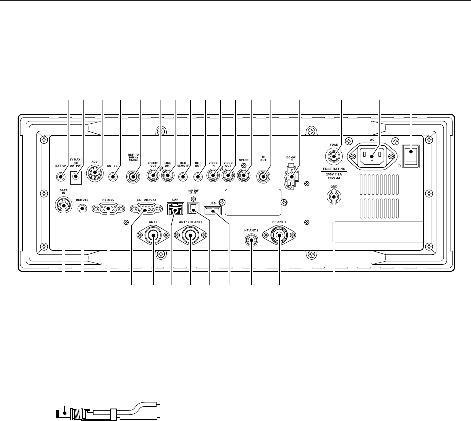
■Rear panel
q
EXTERNAL SPEAKER JACK [EXT-SP]
(p. 2-6)
Connects an external speaker (4–8 ), if desired.
wDC OUTPUT JACK [DC OUTPUT] (p. 2-6)
Outputs regulated 15 V DC (approx.) for external
equipment. Connected in parallel with 13.8 V out-
puts of [ACC]. (max. 1 A total)
eACCESSORY SOCKET [ACC] (p. 2-6)
Enables connection of external equipment such as
an automatic antenna selector, a TNC for data com-
munications, etc.
• See p. 2-12 for socket information.
rANTENNA SELECTOR VOLTAGE OUTPUT
JACK [ANT SEL]
Outputs regulated 13.8 V DC (max. 100 mA) for ex-
ternal preamplifier or antenna selector, etc.
tREFERENCE SIGNAL INPUT/OUTPUT
TERMINAL [REF I/O 10MHz–10dBm]
Inputs/outputs a 10 MHz reference signal.
ySPEECH OUTPUT JACK [SPEECH OUT] (p. 2-9)
Outputs an operating frequency, mode, S-meter in-
dication and time with a synthesized voice when
pushing [SPCH] or scan stopped.
• Turn ON the “REC SPCH” in the others set mode to ac-
tivate this jack when scan stopped. (p. 11-11)
• Output level can be adjusted in ACC set mode. (p. 11-7)
uLINE OUTPUT JACK [LINE OUT]
Audio output jack for tape recorder. The fixed audio
output level is set for a tape recorder AUX jack.
iRECORDER REMOTE JACK [REC REMOTE]
Controls the operation of a tape recorder for record-
ing. Connects to the REMOTE jack on a tape
recorder.
oDETECTOR OUTPUT JACK [DET OUT]
Outputs the detector output signal.
!0 VIDEO INPUT JACK [VIDEO IN]
Accepts video signals for display on the LCD moni-
tor when the [DISPLAY] switch is ON.
!1 VIDEO OUTPUT JACK [VIDEO OUT]
Outputs video signals when TV frequencies with
WFM mode are received. The NTSC M, PAL B/G,
PAL I, PAL D and SECAM K system can be ac-
cepted.
!2 SPARE JACK [SPARE] (p. 2-3)
No connection.
!3 IF OUTPUT JACK [IF OUT] (p. 2-3)
Outputs a 10.7 MHz IF signal.
Output level is the same level as an antenna input
signal or below (when the AGC function is activated
or attenuator is ON.)
!4 DC-DC POWER SOCKET [DC-DC IN] (p. 2-6)
Accepts a regulated 13.5 to 15 V DC input. This
socket does not accept voltage from a non-regu-
lated power source such as a vehicle’s battery.
+
_
_
1PANEL DESCRIPTION
qw e r t yuio!0 !1 !2 !3 !4 !5 !6 !7
@9 @7 @3@4@5@6 !9 !8@0@1@2@8

1-9
!5 FUSE HOLDER [FUSE] (p. 12-8)
Holds a 4 A fuse (100 V/120 V versions) or 2 A fuse
(230 V/240 V versions) for internal AC power sup-
ply protection. Cuts off the AC input when over-cur-
rent occurs.
CAUTION: Always use the correct fuse for AC
input power. Using a fuse rated for a different
input power may damege your house electrical
system or the receiver.
!6 AC POWER SOCKET [AC] (p. 2-5)
Connects the supplied AC power cable to an AC
line-voltage receptacle.
!7 MAIN POWER SWITCH [I/O] (p. 3-2)
Turns the internal power supply ON or OFF.
!8 GROUND TERMINAL [GND] (p. 2-2)
Connect this terminal to a ground to prevent electri-
cal shocks, TVI, BCI and other problems.
!9 HF ANTENNA CONNECTOR 1 [HF ANT 1]
(p. 2-5)
Accepts a 50 antenna for HF bands with a PL-
259 plug connector.
@0 HF ANTENNA CONNECTOR 2 [HF ANT 2]
(p. 2-5)
Accepts a 50 antenna for HF band with an RCA
connector.
@1 USB CONNECTOR [USB]
Connects USB equipment such as a memory
media, hub or keyboard.
@2 S/P DIF OUTPUT TERMINAL [S/P DIF OUT]
(p. 2-7)
Connects external equipment that supports S/P DIF
output.
@3 HF ANTENNA CONNECTOR 3/ANTENNA CON-
NECTOR 1 [ANT 1/HF ANT 3] (p. 2-5)
Accepts a 50 antenna with a Type-N connector.
Covers the HF bands and 30–1150 MHz frequency
range.
@4 ETHERNET CONNECTOR [LAN] (pgs. 2-7, 15-6)
Connects to a PC through a LAN (Local Area Net-
work).
@5 ANTENNA CONNECTOR 2 [ANT 2] (p. 2-5)
Accepts a 50 antenna with a Type-N connector.
Covers the 1150–3335 MHz frequency range.
@6 EXTERNAL DISPLAY TERMINAL
[EXT-DISPLAY] (p. 2-10)
Connects to an external display monitor.
• At least 800×600 pixel display is necessary.
@7 RS-232C TERMINAL [RS-232C] (p. 2-6)
Connects to a PC using a D-sub 9-pin RS-232C
cable.
Can be used for remote control of the IC-R9500
without the optional CT-17, or the FSK decoded sig-
nal output. The [RS-232C] interface is wired as a
modem (DCE).
@8 CI-V REMOTE CONTROL JACK [REMOTE]
(p. 2-6)
➥Connects a PC via the optional CT-17 CI-V LEVEL
CONVERTER for external control of the receiver.
➥Used for transceive operation with another Icom
CI-V transceiver or receiver.
@9 DATA SOCKET [DATA IN]
(pgs. 2-10, 2-12)
Outputs LCD monitor signals (NTSC system).
1
PANEL DESCRIPTION
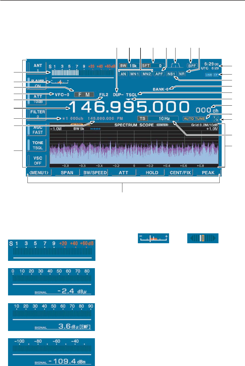
■LCD display
qRSSI METER (p. 3-10)
Shows the received signal strength. Four meter
types, S, dBµ, dBµ(EMF) and dBm meters are se-
lectable.
wCENTER METER
Shows that the received signal is tuned to its center
frequency for FM/WFM or FSK modes.
eMODE INDICATOR (p. 3-7)
Shows the selected receive mode.
rVFO/MEMORY INDICATOR (pgs. 3-3, 7-3)
Indicates the selected VFO number (VFO-0 to VFO-
9) or memory mode.
tIF FILTER INDICATOR (p. 5-12)
Shows the selected IF filter number.
yFREQUENCY READOUTS
Shows the operating frequency.
uSELECT MEMORY CHANNEL INDICATOR (p. 8-12)
Indicates the displayed memory channel is set as a
select memory channel.
iMEMORY CHANNEL READOUTS
➥Shows the selected memory channel contents in
VFO mode.
➥Shows the VFO contents in memory mode.
• FM/WFM modes • FSK mode
• S-meter
• dBµ meter
• dBµ (EMF) meter
• dBm meter
1-10
1PANEL DESCRIPTION
@3
@1
!3
!2
@0
@4@6@8 @7@9 @5 @2
!4
!0
o!1
r
w
u
y
!8
!7
!6
q
t!5
!9
e
i

1-11
1
PANEL DESCRIPTION
oMULTIFUNCTION SWITCH GUIDE
Indicates the function of the multifunction switches.
!0 LCD FUNCTION SWITCH GUIDE
Indicates the function of the LCD function switches
([F-1] – [F-7]).
!1 MULTIFUNCTION SCREEN
Shows the screens for the spectrum scope, voice
recorder, memory channel list, scan, FSK decoder,
IF filter selection or set modes, etc.
!2 TUNING STEP INDICATOR (p. 3-5)
Shows the selected tuning step.
!3 1/4 FUNCTION INDICATOR (p. 3-6)
Appears when the 1/4-speed tuning function is acti-
vated in CW and FSK modes.
!4 AUTOMATIC TUNE INDICATOR (p. 5-17)
“ ”blinks during automatic tuning. This
feature is active in AM, SSB and CW mode.
!5 MEMORY CHANNEL INDICATOR (p. 7-3)
Indicates the selected memory channel number.
!6 TUNING DIGIT INDICATOR (p. 3-5)
Shows the tuneable digit when rotating the main
dial.
!7 TONE/DTCS/NAC/SELECTIVE SQUELCH
INDICATOR
➥“TSQL” or “DTCS” appears when the tone
squelch or DTCS squelch is set in FM mode.
(p. 4-4)
➥“NAC” or “SEL” appears when the NAC squelch
or selective squelch is selected in P25 mode.
(Requires optional UT-122.) (p.4-19)
!8 BANK INDICATOR (p. 7-3)
Appears when the bank limit function is in use and
indicates the selected bank number.
• BANK-0 to BANK-9, BANK-A (AUTO MW), BANK-S
(SKIP) and BANK-P (SCAN EDGE) are selectable.
!9 NOISE BLANKER INDICATOR (p. 5-15)
“NB1” or “NB2” appears when either noise blanker 1
or noise blanker 2 is ON. This function is not avail-
able for FM/WFM or P25 mode.
@0 CF CARD/USB-MEMORY INDICATOR (p. 11-16)
➥“ ” appears when CF card is correctly con-
nected and blinks while CF card is active.
• This indicator is normally stayed ON.
➥“ ” appears when USB equipment (USB-
Memory or keyboard, etc) is connected, and
blinks while it is active.
@1 CLOCK READOUT (p. 10-2)
Shows the current time. Local and UTC time can in-
dicate at the same time.
@2 NOISE REDUCTION INDICATOR (p. 5-16)
Appears when noise reduction function is in use.
@3 BANDPASS FILTER INDICATOR
Appears when the narrow filter (500 Hz or less) is
selected during CW or FSK operation.
@4 PASSBAND WIDTH INDICATOR (p. 5-11)
Graphically displays the passband width for twin
PBT operation and center frequency for IF shift op-
eration.
@5 AUDIO PEAK FILTER INDICATOR (p. 4-10)
Appears when the audio peak filter function is in use.
This function is available in CW mode
@6 SHIFT FREQUENCY INDICATOR (p. 5-11)
Shows the shift frequency of the IF filter.
@7 NOTCH FILTER INDICATOR (p. 5-16)
➥“ ” appears when the auto notch function is in
use. This function is available in FM, WFM, AM
and SSB modes.
➥“ ” or “ ” appear
s when the manual notch
filter function is in use. This function is available in
AM, SSB, CW and FSK mode.
@8 BAND WIDTH INDICATOR (p. 5-11)
Shows the passband width of the IF filter.
@9 DUPLEX INDICATOR (p. 4-3)
“DUP–” or “DUP+” appears when the negative duplex
or positive duplex operation is selected, respectively.
MN2
MN1
AN
USB
CF
AUTO TUNE
1-12
1PANEL DESCRIPTION
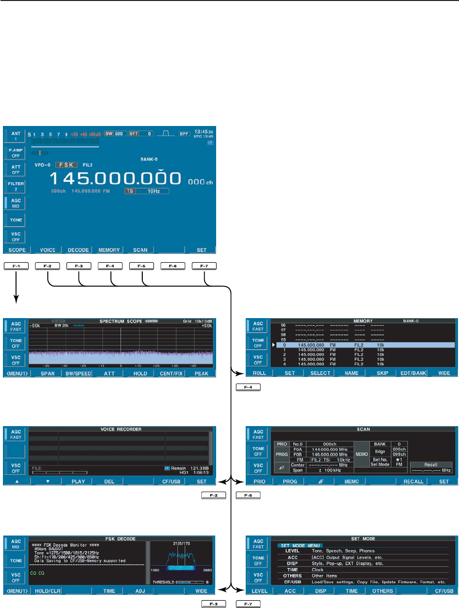
■Screen menu arrangement
The following screens can be selected from the start
up screen. Choose the desired screen using the fol-
lowing chart.
Pushing [EXIT/SET] several times returns to the start
up screen. See p. 11-3 for set mode arrangement.
• Spectrum scope screen (p. 5-2)
• Voice recorder screen (p. 6-3)
• FSK decoder screen (p. 4-14)
• Memory channel screen (p. 7-4)
• Scan screen (p. 5-5)
• Set mode menu screen (p. 11-2)

2-1
INSTALLATION AND CONNECTIONS Section 2
■Unpacking ……………………………………………………………… 2-2
■Selecting a location …………………………………………………… 2-2
■Grounding ……………………………………………………………… 2-2
■Antenna connection …………………………………………………… 2-3
■TV jumper cable connection …………………………………………… 2-4
■Carrying handle attachment …………………………………………… 2-4
■Rack mounting handle detachment …………………………………… 2-4
■Required connections ………………………………………………… 2-5
DRear panel …………………………………………………………… 2-5
■Advanced connections ………………………………………………… 2-6
DFront panel …………………………………………………………… 2-6
DRear panel—1 ……………………………………………………… 2-6
DRear panel—2 ……………………………………………………… 2-7
■Tape recorder connections …………………………………………… 2-8
DRecording from the front panel or rear panel …………………… 2-8
DSeparately recording audio and frequency ……………………… 2-9
■Monitor display connection …………………………………………… 2-10
■Transceive function …………………………………………………… 2-10
■FSK and AFSK (SSTV) connections ………………………………… 2-11
■Accessory connector information …………………………………… 2-12
CAUTION!: The receiver weighs approx. 20 kg (44 lb). Al-
ways have two people available to carry, lift or
turn over the receiver.
2-2
■Unpacking
After unpacking, immediately report any damage to the
delivering carrier or dealer. Keep the shipping cartons.
For a description and a diagram of accessory equip-
ment included with the IC-R9500, see ‘Supplied ac-
cessories’ on p. iii of this manual.
■Selecting a location
Select a location for the receiver that allows adequate
air circulation and access to the front and rear panels.
Do not place in areas subject to extreme heat, cold, or
vibrations, or near TV sets, radios and other electro-
magnetic sources.
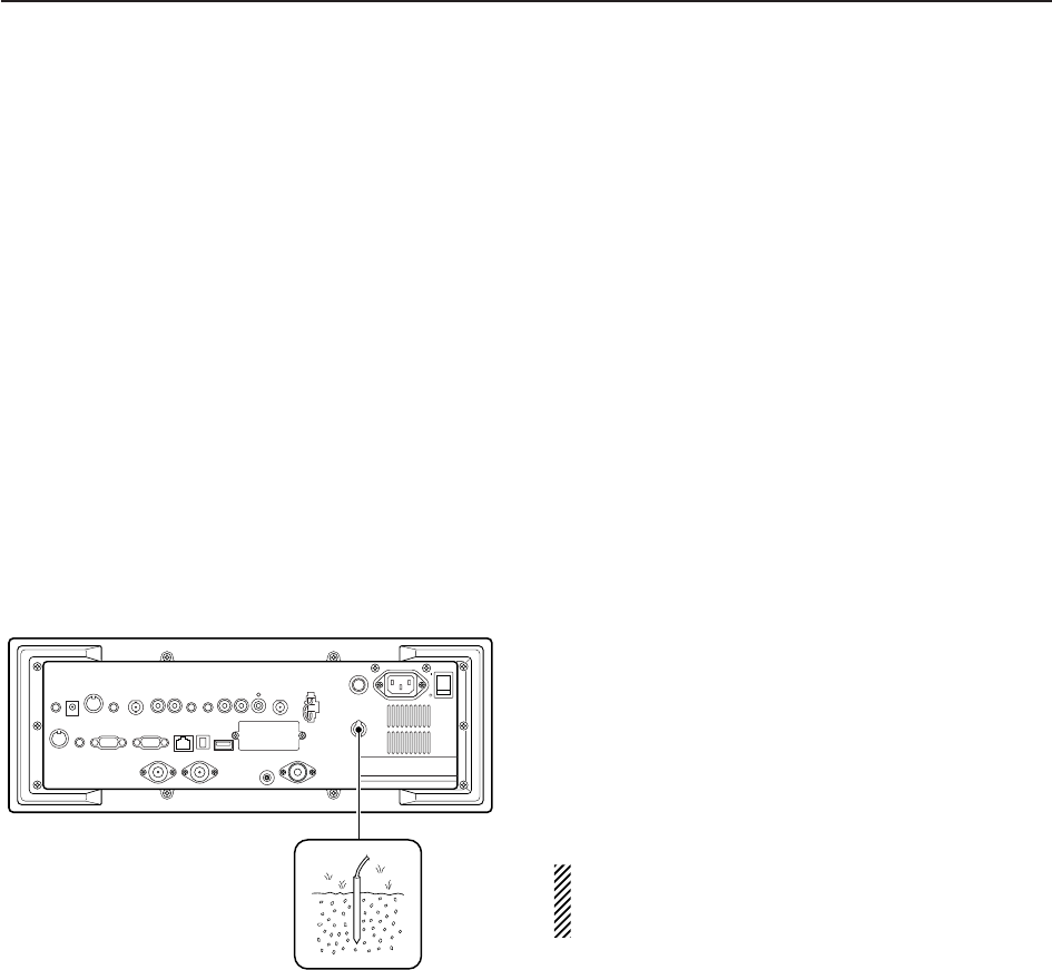
■Grounding
To prevent electrical shock, television interference
(TVI), broadcast interference (BCI) and other prob-
lems, ground the receiver through the GROUND ter-
minal on the rear panel.
For best results, connect a heavy gauge wire or strap
to a long earth-sunk copper rod. Make the distance be-
tween the [GND] terminal and ground as short as pos-
sible.
RWARNING: NEVER connect the [GND]
terminal to a gas or electric pipe, since the connec-
tion could cause an explosion or electric shock.
2INSTALLATION AND CONNECTIONS
2-3
■Antenna connection
Your antenna plays a very important role in receiver
operation. If the antenna is poor, your receiver cannot
give you the best performance.
The IC-R9500 requires at least 2 antennas (ANT 1/HF
ANT 3, ANT 2) for full coverage from 100 kHz to 3335
MHz. Select an antenna, such as a well matched 50
antenna and feedline. When you wish to use a long
wire antenna for short wave bands, use one as long as
possible (at least 10 m, 32.8 ft).
CAUTION: Protect your receiver from lightning by
using a lightning arrestor.
2
INSTALLATION AND CONNECTIONS
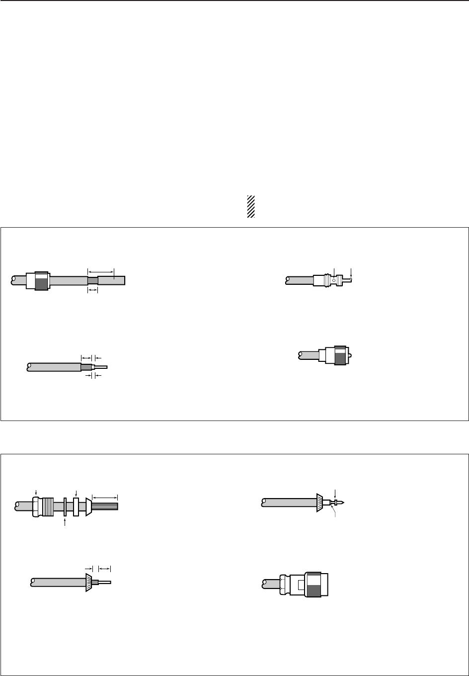
PL-259 CONNECTOR INSTALLATION EXAMPLE
30 mm §9⁄8in 10 mm §3⁄8in 1–2 mm §1⁄16 in
30 mm
10 mm (soft solder)
10 mm
1–2 mm
solder solder
Soft
solder
Coupling ring
Slide the coupling ring
down. Strip the cable
jacket and tin the
braid.
Slide the connector
body on and solder it.
Screw the coupling
ring onto the connector
body.
Strip the cable as
shown at left. Tin the
centerr conductor.
q
w
e
r
TYPE-N CONNECTOR INSTALLATION EXAMPLE
30 mm §9⁄8in 10 mm §3⁄8in 1–2 mm §1⁄16 in
15 mm
Clamp
3 mm 6 mm
Center conductor
Washer
Nut Rubber gasket
qe
rw
Slide the nut, washer,
rubber gasket and
clamp over the
coaxial cable, then
cut the end of the
cable evenly.
Tin the center conductor.
Install the center conductor
pin and solder it.
Carefully slide the plug
body into place aligning
the center conductor pin
on the cable. Tighten the
nut onto the plug body.
• Be sure the center pin is
flush with the end of the
plug body.
Strip the cable and
fold the braid back
over the clamp.
Plug body
No space
Solder hole
2-4
2INSTALLATION AND CONNECTIONS
■TV jumper cable connection
Connect the RCA cable between [VIDEO IN] and
[VIDEO OUT].
When connecting external video equipment, connect
the unit between [VIDEO IN] and [VIDEO OUT] con-
nectors.
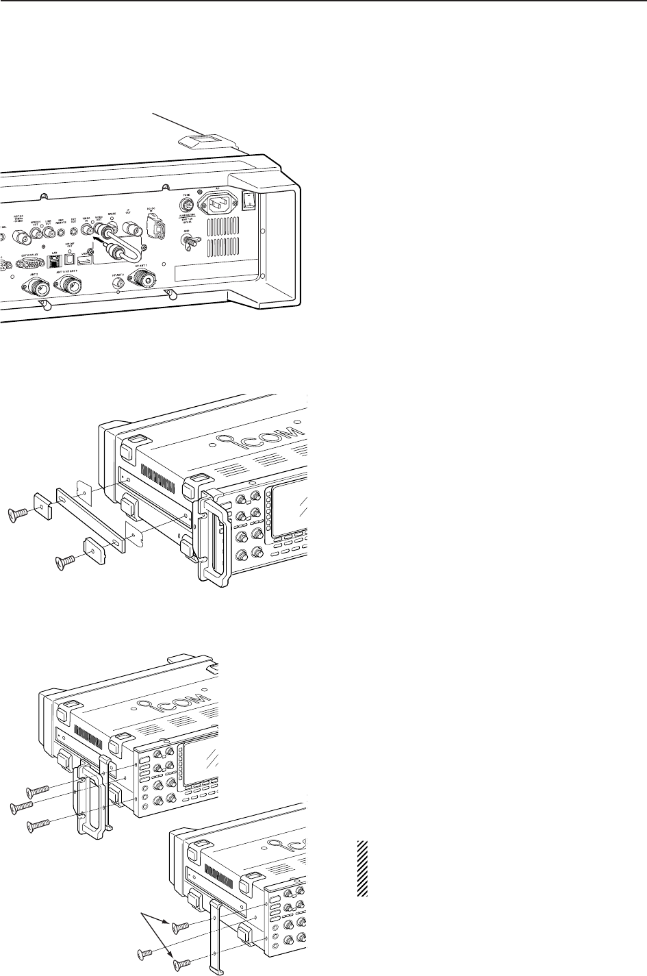
■Carrying handle attachment
Attach the supplied Carrying handles as shown at left.
■Rack mounting handle detachment
When removing the rack mounting handles, use the
supplied screws for attach the side plates.
qRemove the 6 screws from the rack mounting han-
dles from both side. And remove the rack mounting
handles and side plates.
wAttach the removed side plates to original position,
then tighten the supplied 4 screws (FH M4×12).
Tighten the supplied 2 screw (PH M4×8) for hiding
screw holes for both side.
CAUTION: NEVER replace the any other than
specified screws for side plate atachment or hid-
ing screw holes. If long screw is used, it is
caused to damage the receiver‘s inside board.
FH M4×12 mm
FH M4×16 mm
PH M4×8 mm
q
w
PH: Pan head
FH: Flat head
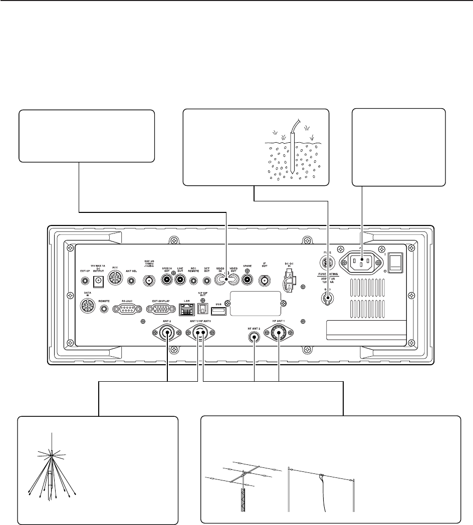
■Required connections
DRear panel
HF Antenna 1, 2, 3 (p. 2-3)Antenna 1, 2 (p. 2-3)
Connects the VHF,
UHF wide band anten-
nas.
ANT1: 30–1150 MHz,
ANT2: 1150–3335 MHz
The optional AH-7000 is available for 25
MHz to 1.3 GHz coverage. Select the active antenna connector. (p.9-3)
[Example]: HF ANT1 for 1.8–18 MHz bands, HF ANT 2 for 21–28
bands, ANT3 for 50 MHz band.
Ground (p. 2-2)
Ground connection
AC outlet
R WARNING:
Use the supplied
AC power cable
only.
[VIDEO IN], [VIDEO OUT]
TV jumper cable must be con-
nected when internal TV tuner
and LCD are in use.
2-5
2
INSTALLATION AND CONNECTIONS
2-6
2INSTALLATION AND CONNECTIONS
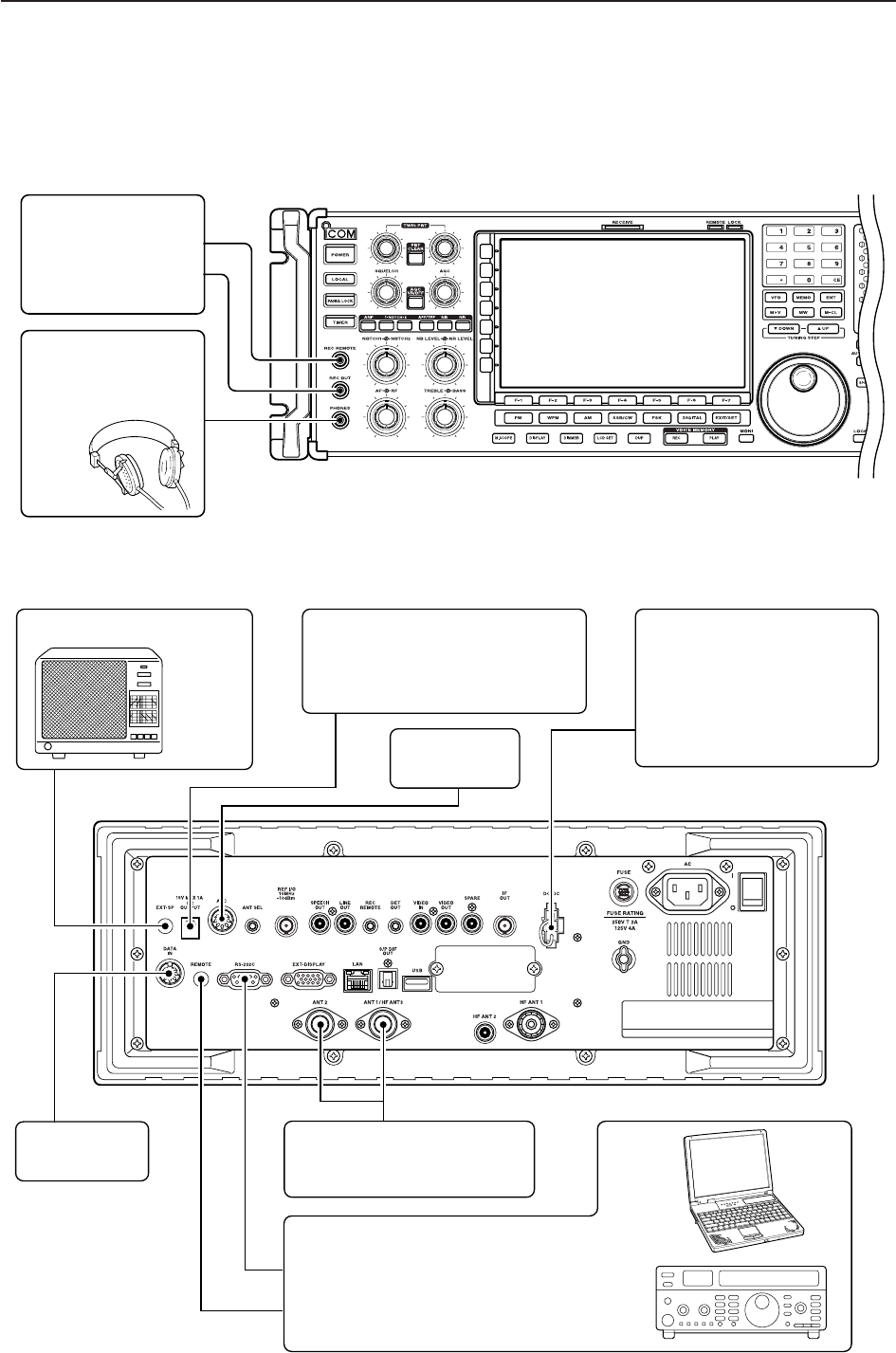
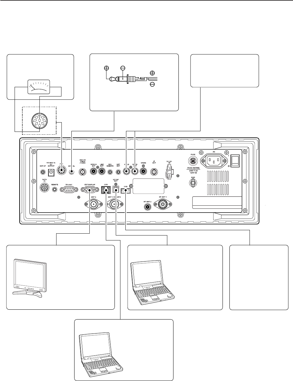
■Advanced connections
DFront panel
DRear panel—1
External speaker (p. 14-4)
ACC socket
(pgs.2-12)
DATA socket
(pgs.2-12)
Antenna 1, 2
Connects a pre-amplifier,
converter, etc.
SP-20
(option)
[REMOTE], [RS-232C] (p. 13-2)
Used for computer control and transceive
operation.
The optional CT-17 is required when con-
necting a PC to [REMOTE].
[DC OUTPUT]
Outputs regulated 15 V (approx.)
DC for external equipment power
supply. (max. 1 A capacity)
Connects an external pow-
er supply (DC 13.5–15 V at
least 8 A).
Only regulated DC power
may be connected.
[DC-DC IN]
[REC REMOTE],
[REC OUT] (p. 2-8)
Connects a tape re-
corder or other au-
dio equipment.
Accepts headphones
with 4–16 1 impe-
dance.
Headphones
2-7
2
INSTALLATION AND CONNECTIONS
DRear panel—2
1
2
3
45
67
8
External Display
Connects a PC-style
monitor display (at least
800×600 resolution).
Video output signal can
be turned ON and OFF
in set mode (p. 11-9)
Video equipment
Connects a video re-
corder, etc.
Connects a PC for
audio signal data
input/output.
Connects a USB
equipment such as
memory, hub or
keyboard.
48 kHz, 16-bit
output
[S/P DIF IN/OUT] [USB]
Connects a PC
via a LAN for CPU
firmware update.
[METER]
Connects an external
meter, etc.
Meter
Ethernet connector (p. 15-6)
MOUT
GND [ACC]
ANT SEL
When the [ANT] switch is ON:
13.8 V DC output 100 mA max.
2-8
2INSTALLATION AND CONNECTIONS
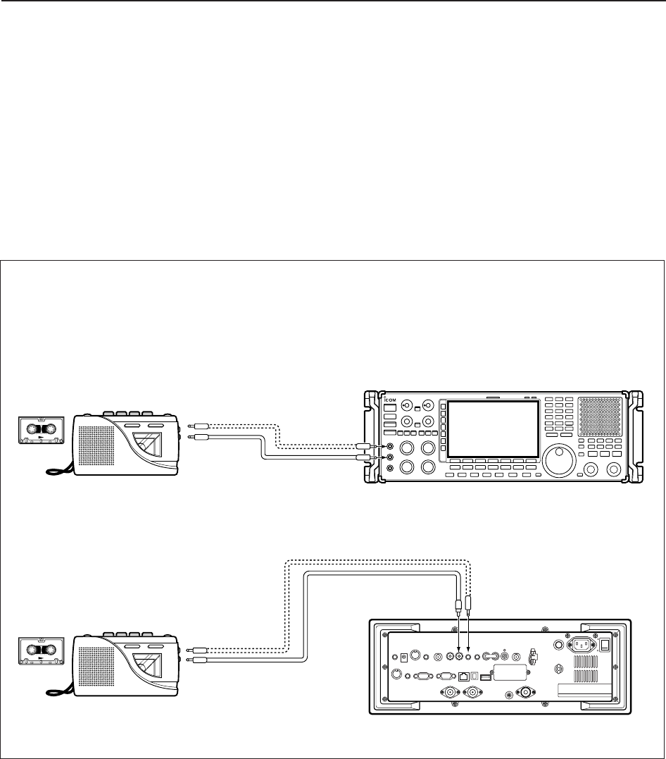
■Tape recorder connections
DRecording from the front panel or rear panel
FRONT
• Recording from the front panel
• Recording from the rear panel
REAR
[REC
REMOTE]
[REC OUT]
350 mVrms
4.7 k1
[LINE OUT]
350 mVrms
4.7 k1
[AUX IN] or
[LINE IN] jack
[REMOTE] jack
[AUX IN] or [LINE IN] jack
[REMOTE] jack
[REC REMOTE]
When you wish to control a tape
recorder via the REMOTE jack.
When you wish to control a tape
recorder via the REMOTE jack.
The [REC REMOTE] jack is grounded when a signal
is received and squelch opens. If a tape recorder has
a control terminal, this jack can be used for recording
control. (2 A/DC max.)
The [REC OUT] or [LINE OUT] jack has 350 mV
rms/4.7 koutput for connection to other audio equip-
ment.
The [REC REMOTE] jack is grounded when a signal
is received and squelch opens. If a tape recorder
has a control terminal, this jack can be used for
recording control. (2 A/DC max.)
The [REC OUT] or [LINE OUT] jack has 350 mV
rms/4.7 koutput for connection to other audio
equipment.
2-9
2
INSTALLATION AND CONNECTIONS
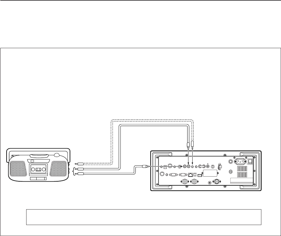
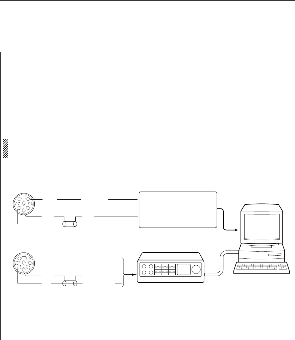
DSeparately recording audio and frequency
When using a stereo tape recorder for recording,
received audio and a frequency with a synthesized
voice can be separately recorded.
When recording this way, you can search ahead of
the audio signal recorded in the tape recorder using
the frequency recording channel search.
• Be sure the “REC SPEECH” item is turned ON, and “SPEECH Mix” item is select OFF in the others set
mode (p. 11-11).
REAR
[LINE OUT]
350 mVrms
4.7 k1
[SPEECH OUT]
350 mVrms
4.7 k1
[AUX IN] jacks L and R
[REMOTE] jack
[REC REMOTE]
When you wish to control a tape
recorder via the REMOTE jack.
2-10
2INSTALLATION AND CONNECTIONS
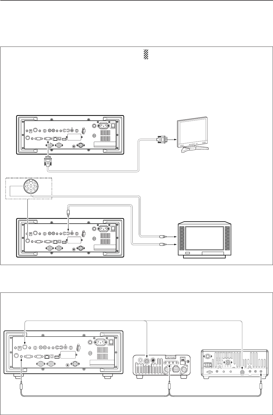
■Transceive function
Icom CI-V transceivers or receivers can be connect-
ed via the [REMOTE] jack. The frequency and mode
settings will follow* when either radio is changed.
* When a set frequency is out-of-range for one of the con-
nected transceivers or receivers, the connected radio’s
frequency/mode does not change.
Connect to [REMOTE] jack
[ACC]
Pin 3 Connect [ACC] socket when the IC-
R9500 is connected with transceiver.
This connection mutes the IC-R9500
when transceiver transmits.
• Be sure the “CI-V Transceive” item is turned ON in the others set mode (p. 11-14).
■Monitor display connection
A monitor display can be connected to the IC-R9500
via the [DATA IN] socket and [EXT-DISPLAY]. You
can monitor the LCD monitor information on a large
size display.
The IC-R9500 includes a picture signal decoder.
When connecting a TV set equipped with a VIDEO IN
jack, you can monitor TV signals such as amateur
TV.
NOTE: Video output from [DATA IN] is available an
NTSC system only.
External Display
Connects a PC-style
monitor display (at least
800×600 resolution).
Video output signal can
be turned ON and OFF
in display set mode.
(p. 11-9)
1
2
3
45
67
8
TV set
Video output signal can be selec-
ted ‘VIDEO IN’ or ‘LCD’ in display
set (Video) mode. (p. 11-25)
*
[EXT-DISPLAY]
VIDEO
GND
[DATA IN] [VIDEO OUT]
[VIDEO IN]
TV signal only
*LCD output including TV signal
or
2-11
2
INSTALLATION AND CONNECTIONS
To connect a terminal unit, TNC or scan converter,
refer to the diagram below.
qConnect a terminal unit as below.
wSelect FSK mode (or USB, CW modes for HF
band data communications).
eSet the receiver to the desired frequency as shown
to the right.
rSet the connected terminal unit to the appropriate
settings.
• Refer to the terminal unit’s instructions.
The narrow filter settings may not pass FSK sig-
nals. Be sure to select the appropriate IF filters cor-
responding to the signal width. (p. 5-12)
• Frequency settings depend on the mode used.
FM mode:
[Setting frequency (displayed freq.)] = [Desired freq.]
USB mode:
[Setting frequency (displayed freq.)] =
[Desired freq.] – [Center of Mark and Space freq.]
CW narrow mode:
[Setting frequency (displayed freq.)] = [Desired freq.]
– [Center of Mark and Space freq.] + [600 Hz]
LSB mode (for amateur RTTY):
[Setting frequency (displayed freq.)] = [Desired freq.]
+ [Mark freq.]
■FSK and AFSK (SSTV) connections
RS-232C
Connect to serial port, parallel
port, speaker jack, and line
IN/OUT jack, etc.
See the instruction manual of the
application for details.
• When using a PC application
• When using a TNC
1
2
3
4
5
6
78
Rear panel view
AF
GND
SQLS
AUDIO INPUT
GND
SQELCH IN
1
2
3
4
5
6
78
Rear panel view
[ACC]
[ACC]
AF
GND
SQLS
AUDIO INPUT
GND
SQELCH IN
TNC or scan converter
Personal computer
2-12
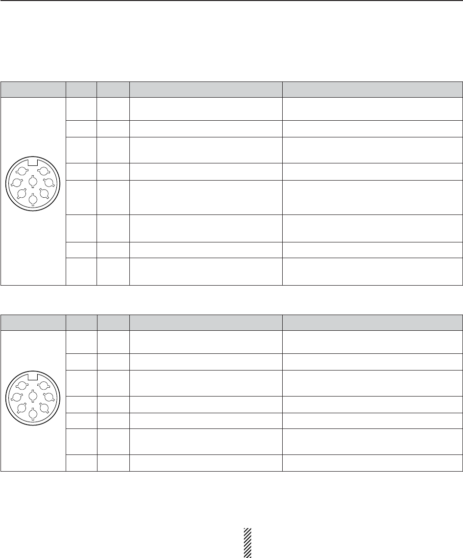
■Accessory connector information
2INSTALLATION AND CONNECTIONS
ACC
PIN No.
NAME DESCRIPTION SPECIFICATIONS
NOTE: If the beep level limit is in use, the beep tone
decreases from the fixed level when the [AF] con-
trol is rotated above a specified level. (p. 11-6)
1
2
3
45
67
8
1
2
3
4
5
6
7
8
ANTS
GND
SEND
NC
AF
SQLS
13.8 V
MOUT
Outputs 5 V when the [ANTENNA]
switch is ON.
Connects to ground.
When grounded, attenuator activates
and then audio is muted.
No connection
AF detector output.
Fixed, regardless of [AF] position in
default settings. (see notes below)
Squelch output.
Goes to ground when squelch opens.
13.8 V output when power is ON.
Output S-meter level.
Output current : Less than 100 µA
Output impedance : 10 k
GROUND level : –0.5 to +0.8 V
Input current : Less than 20 mA
Output impedance : 47 k
Output level : 100–300 mV rms
Squelch open : Less than 0.3 V/5 mA
Squelch closed : More than 6.0 V/100 µA
Output current : 100 mA
Output voltage : 0 to approx. 4 V
Output impedance : 10 k
Output level : 1 V p-p ±0.2 V
Output impedance : 75
DATA IN
PIN No.
NAME DESCRIPTION SPECIFICATIONS
1
2
3
45
67
8
1
2
3
4
5
6
7, 8
DATA
IN
GND
VIDEO
GND
NC
DATA
OUT
NC
—
Connects to video ground.
Video signal output.
(NTSC system only)
—
No connection
—
No connection

3-1
BASIC OPERATIONS Section 3
■When first applying power (CPU resetting) ………………………… 3-2
■Initial settings …………………………………………………………… 3-2
■Selecting VFO mode …………………………………………………… 3-3
■Selecting memory mode ……………………………………………… 3-3
■Frequency setting ……………………………………………………… 3-4
DDirect frequency entry with the keypad …………………………… 3-4
DTuning with the main dial …………………………………………… 3-5
DSelecting a tuning step ……………………………………………… 3-5
DAuto tuning step function …………………………………………… 3-6
D1⁄4tuning step function ……………………………………………… 3-6
■Operating mode selection ……………………………………………… 3-7
■Volume setting ………………………………………………………… 3-8
■RF gain adjustment …………………………………………………… 3-8
■Squelch level adjustment ……………………………………………… 3-8
■Audio tone adjustment ………………………………………………… 3-9
DTreble level adjustment ……………………………………………… 3-9
DBass level adjustment ……………………………………………… 3-9
■Meter indication selection …………………………………………… 3-10
DMeter type selection ……………………………………………… 3-10
3-2
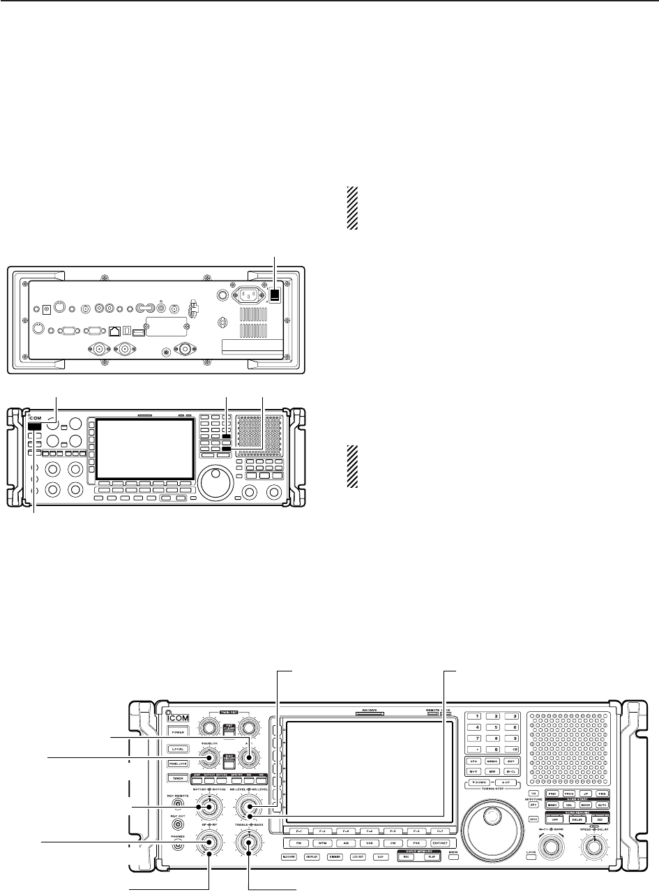
■When first applying power (CPU resetting)
Before first applying power, make sure all connections
required for your system are complete by referring to
Section 2. Then, reset the receiver using the following
procedure.
Resetting CLEARS all programmed contents in
memory channels and returns programmed values
in set mode to default values.
qTurn the main power ON with [I/O] on the rear
panel.
• The receiver power is still OFF and the [POWER] indi-
cator lights orange.
wWhile pushing and holding [CE] and [M-CL], push
[POWER] to turn power ON.
• The CPU is reset.
• The CPU start-up takes approx. 5 sec.
• The receiver displays its initial VFO frequencies when
resetting is complete.
eChange the set mode settings after resetting, if de-
sired.
In cooler temperatures, the LCD may appear dark
and unstable after turning power ON. This is normal
and does not indicate any equipment malfunction.
■Initial settings
After resetting the receiver, set controls as shown in
the figure below.
[AF]
: Max. counter clockwise
[RF]: Max. clockwise
[AGC]: 12 o’clock
[NR LEVEL]
: Max. counter clockwise
[NB LEVEL]
: Max. counter clockwise
[NOTCH1]/[NOTCH2]
: 12 o’clock
[TREBLE]/[BASS]: 12 o’clock
[SQL]
: Max. counter clockwise
[CE] [M-CL]
[I/O]
[Power indicator]
[POWER]
3BASIC OPERATIONS
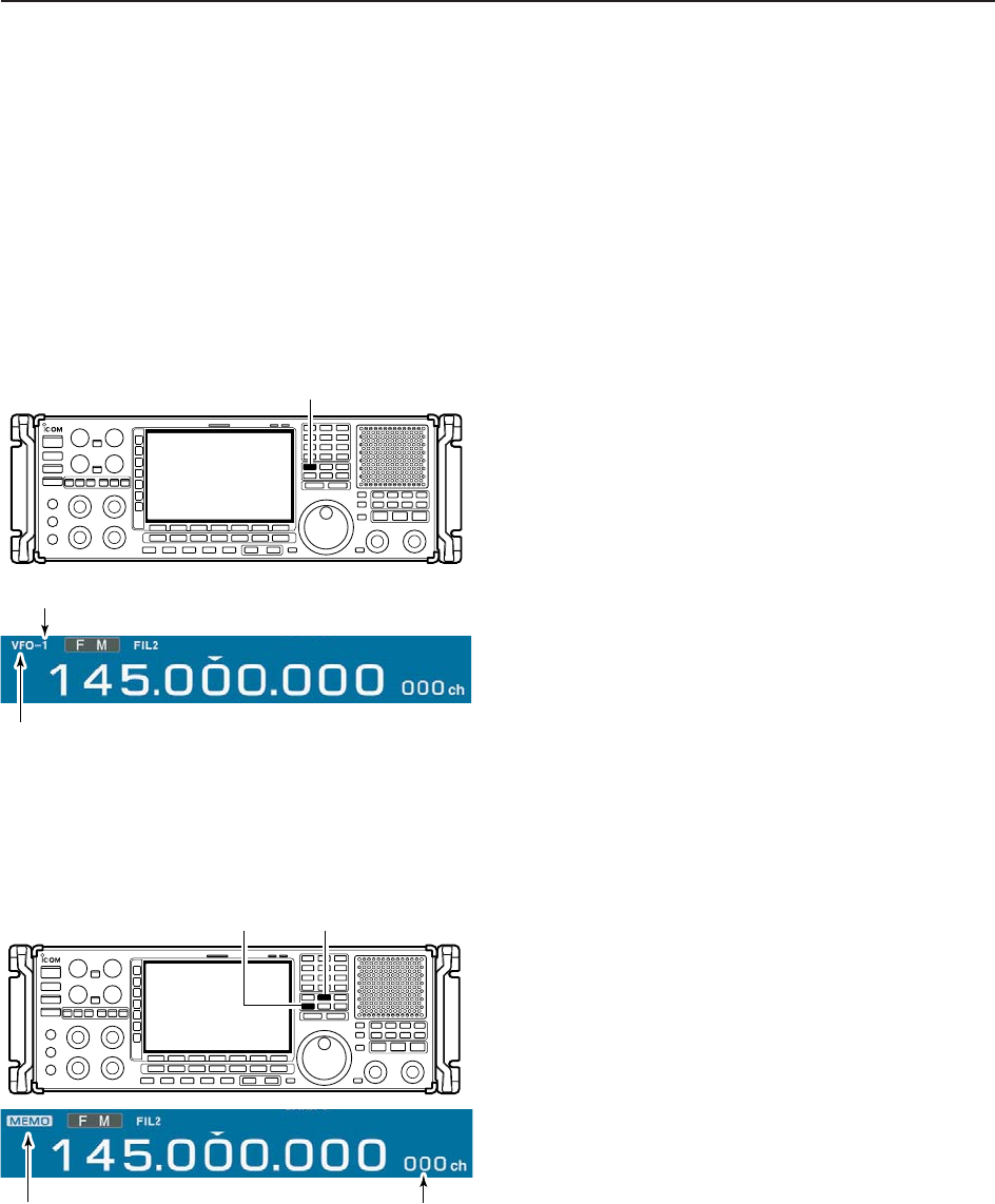
■Selecting VFO mode
VFO is an abbreviation of Variable Frequency Oscilla-
tor, and is commonly referred to as a main tuning func-
tion. Frequency, mode and other receiver settings are
stored as a set of VFO data.
The main dial is often called the “VFO knob.”
The IC-R9500 stores ten sets of VFO data. You can
use the desired VFO to call up a frequency and oper-
ating mode for operation.
➥Push [VFO] to select (last selected) VFO mode.
• One of “VFO-0” to “VFO-9” appears when in VFO mode.
➥Push the desired VFO number (0 to 9) using the
keypad, then push [VFO] to select the desired VFO
mode.
• One of “VFO-0” to “VFO-9” appears when in VFO mode.
■Selecting memory mode
➥Push [MEMO] to select memory mode.
• The memory indicator appears when in memory mode.
• Pushing and holding [M≈V] for 1 sec. transfers the con-
tents of the selected memory channel to VFO*. (p. 7-5)
*Only last selected VFO (VFO-0 to VFO-9) is overwrit-
ten.
Memory indicator Memory channel
number
[MEMO][M≈V]
“VFO” indicator
VFO number
[VFO]
3-3
3
BASIC OPERATIONS
■Frequency setting
There are two ways to set a frequency: with the main
dial or keypad. Use both in combination for quick tun-
ing.
• If the panel lock function is activated, the panel
lock indicator lights, and any switches, keys and
controls do not function. In this case, push [PANEL
LOCK] to deactivate the panel lock function. (see
p. 9-2 for details)
• The dial lock function also locks the main dial. To
deactivate the dial lock function, push [LOCK].
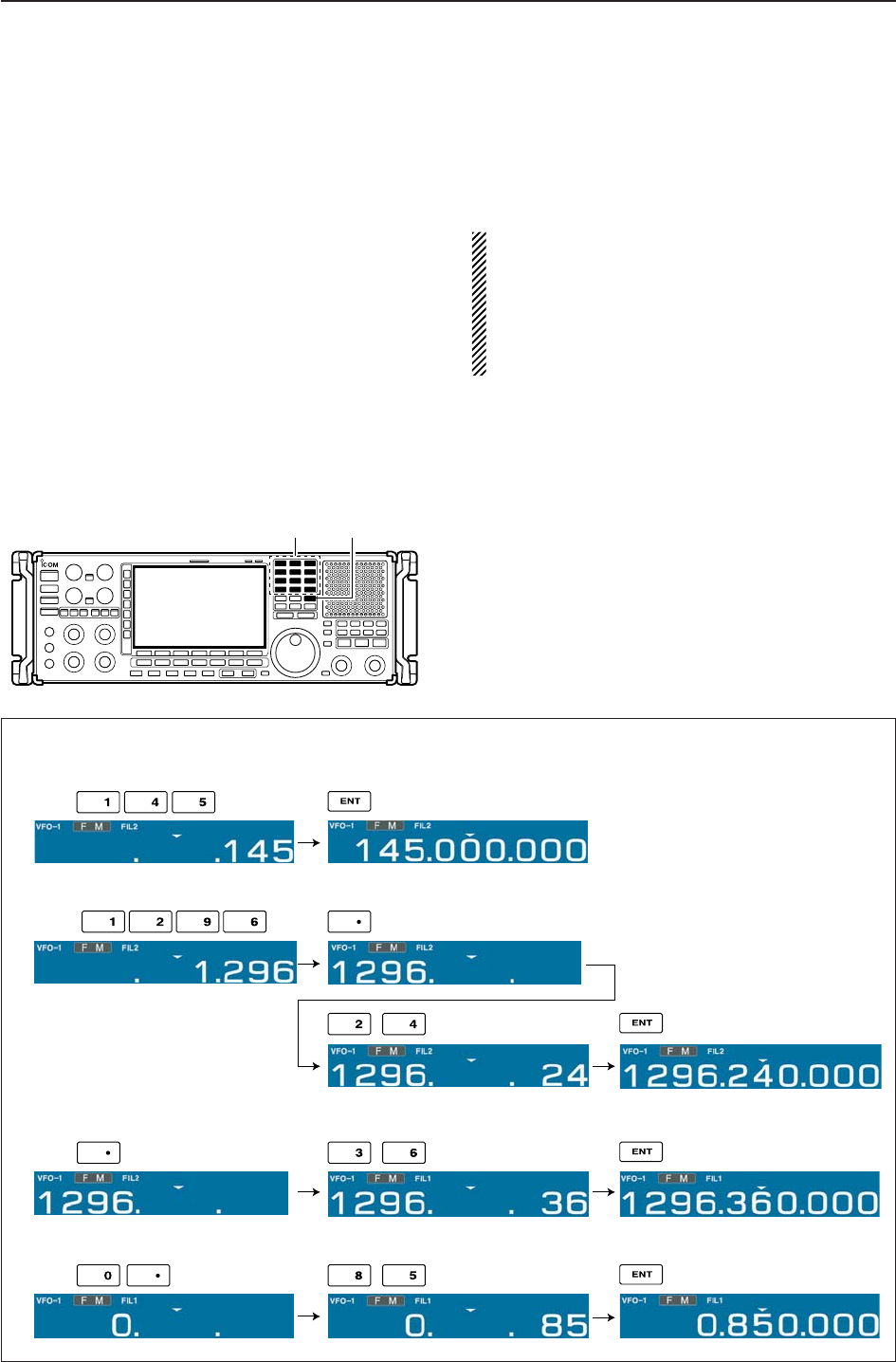
DDirect frequency entry with the keypad
The receiver has a keypad for direct frequency entry
as described below.
qInput the desired frequency.
• Push [•] to input “. (decimal point)” between the MHz
units and kHz units.
wPush [ENT] to set the input frequency.
• To cancel the input, push [CE] instead of [ENT].
[EXAMPLE]
145.000000 MHz
Push
1296.24000 MHz
850 kHz (0.85 MHz)
Push
Push
1296.24000 MHz 1296.36000 MHz
Push
Keypad [ENT]
3-4
3BASIC OPERATIONS
3-5
3
BASIC OPERATIONS
DTuning with the main dial
Rotate the main dial to change the frequency.
• The frequency changes in increments determined by
the selected tuning step (see below).
qPush the desired VFO number (0 to 9) and [VFO].
• 10 different sets of VFO data can be selected.
wSelect the desired operating mode. (p.3-7)
• 10 different sets of VFO data can be selected.
ePush [▲UP] or [▼DOWN] to select the desired tun-
ing step.
• Selectable tuning steps can be changed for each oper-
ating mode as shown below.
rRotate the main dial to set the desired frequency.
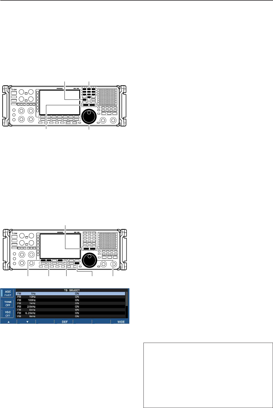
DSelecting a tuning step
14 preset tuning steps plus 1 programmable tuning
step are available. As a default setting, selectable tun-
ing steps can be programmed, depending on the op-
erating mode. Selectable tuning steps can be changed
in TS select screen.
• Selecting selectable tuning steps
qPush and hold [▲UP] or [▼DOWN] for 1 sec. to
enter the TS select screen to set the selectable tun-
ing steps for each operating mode.
wSelect the desired operating mode. (p.3-7)
ePush [F-1 ▲] or [F-2 ▼] to select the desired tuning
step.
•1 Hz, 10 Hz, 100 Hz, 1 kHz, 2.5 kHz, 5 kHz, 6.25 kHz,
9 kHz, 10 kHz, 12.5 kHz, 20 kHz, 25 kHz, 100 kHz,
1 MHz and programmable are selectable.
rRotate the main dial to set the tuning step as the
selectable tuning step if desired.
• Push and hold [F-4•DEF] for 1 sec. to select the default
setting.
tRepeat steps eto rto choose the selectable tun-
ing steps.
yRepeat steps wto rto set the selectable tuning
steps for each operating mode.
uPush [EXIT/SET] (or [▲UP]/[▼DOWN]) to exit the
TS select screen.
[F-1•Y] [F-2•Z] [F-4•DEF] [EXIT/SET] Main dial
TUNING STEP [DOWNZ]/[YUP]
Number key[VFO]
Main dial
TUNING STEP [DOWNZ]/[YUP]
Default settings
FM : All ON
WFM : 20 k, 25 k, 100 k, 1 M, ProgTS
AM : 1 k, 5k, 9 k, 10 k, 1 MHz
SSB : 1, 10, 1 k, 1 MHz
CW : 1, 10, 1 k, 1 MHz
FSK : 1, 10, 1 k, 1 MHz
P25 : 1 k, 2.5 k, 5 k, 6.25 k, 10 k,
12.5 k, 20 k, 25 k, 100 k, 1 MHz
3-6
3BASIC OPERATIONS
• Setting the programmable tuning step
qPush the numeral keys on the keypad that corre-
spond to the tuning step you wish to program.
•Programmable tuning steps can be set between 0.1 and
999.9 kHz in 0.1 kHz steps.
➠To set programmable tuning steps, enter the desired
steps via the keypad, then push [YUP]or [ZDOWN].
wPush [▲UP] or [▼DOWN] to set the programmable
tuning step.
•Programmable tuning step is automatically selected as
the active tuning step.
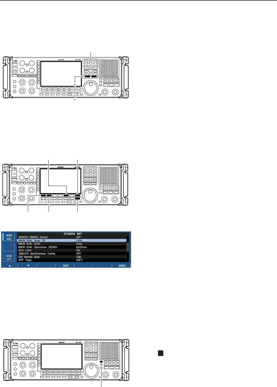
DAuto tuning step function
When rotating the main dial rapidly, the tuning speed
accelerates automatically.
qPush [EXIT/SET] several times to close a multi-
function screen, if necessary.
wPush [F-7•SET] to select set mode menu screen.
• Pushing and holding [EXIT/SET] for 1 sec. also selects
set mode menu screen.
ePush [F-5•OTHERS] to enter the others set mode.
rPush [F-1•Y] or [F-2•Z] to select “MAIN DIAL Auto
TS.”
tRotate main dial to select the desired condition from
HIGH, LOW or OFF.
yPush [EXIT/SET] to exit the set mode.
• HIGN: Approx. 5 times faster
• LOW: Approx. twice faster
• OFF : Auto tuning step is turned OFF.
D1⁄4tuning step function
When operating in CW or FSK, the 1⁄4tuning function
is available. Dial rotation is reduced to 1⁄4of normal
speed when the 1⁄4tuning function is ON for finer tun-
ing control.
➥Push [1/4] to toggle the 1⁄4tuning function ON or
OFF.
• “ ” appears when the 1⁄4tuning function is ON.
1⁄4
[1/4]
[F-1•Y] [F-2•Z] [EXIT/SET]
[F5•OTHERS] [F-7•SET]
Number key
TUNING STEP [DOWNZ]/[YUP]
3-7
3
BASIC OPERATIONS
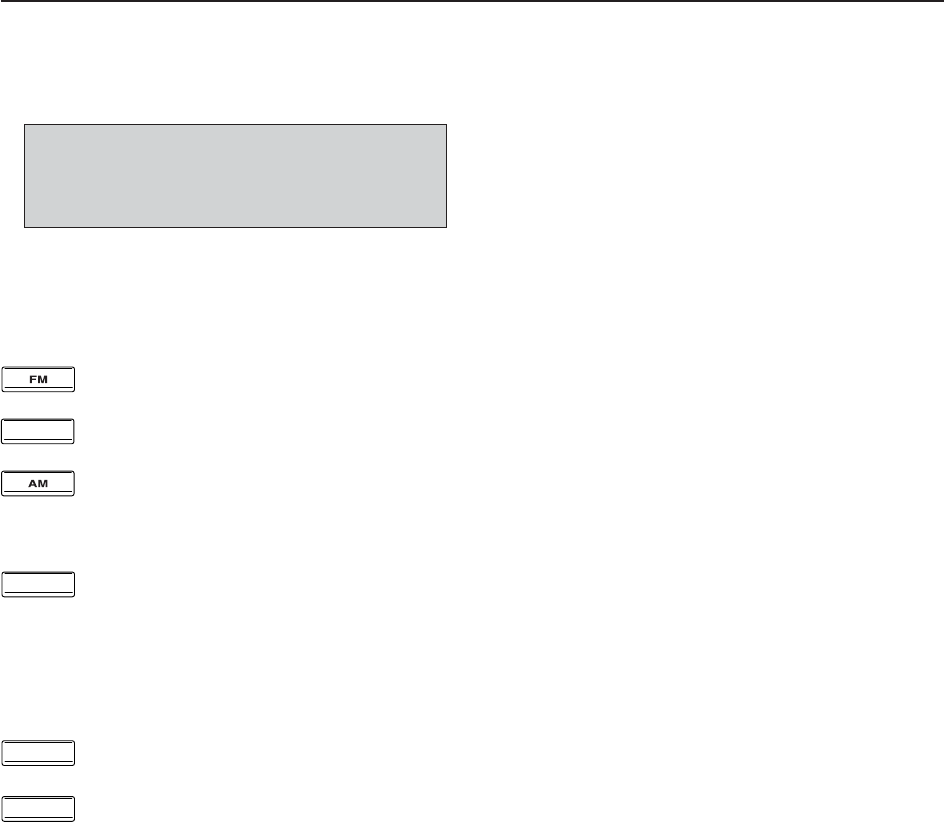
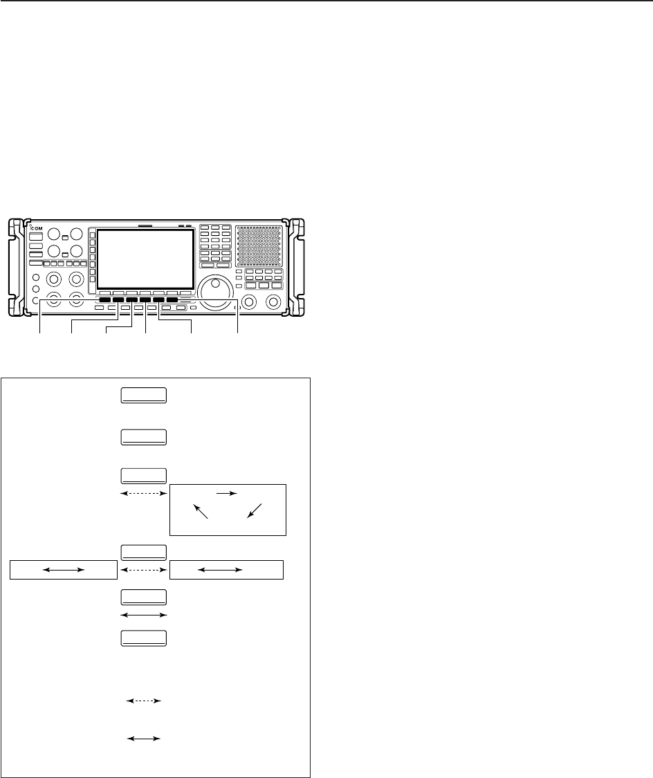
■Operating mode selection
FM, WFM, AM, Synchronous-AM (S-AM(D)/S-
AM(U)/S-AM(L)), SSB (USB/LSB), CW, CW reverse
(CW-R), FSK, FSK reverse (FSK-R) and DIGITAL
(P25*) modes are available in the IC-R9500. Select the
desired operation mode as follows. * P25 requires op-
tional UT-122.
To select a mode of operation, push the desired mode
switch momentarily. Push the switch again to toggle
between AM and S-AM(D)/S-AM(U)/S-AM(L),
USB/LSB and CW/CW-R, if desired. Push and hold the
switch for 1 sec. to toggle between S-AM(D), S-AM(U)
and S-AM(L), USB and LSB, CW and CW-R, FSK and
FSK-R, if desired.
See the diagram below left for the order of selection.
• Selecting FM mode
➥Push [FM] to select FM.
• Selecting WFM mode
➥Push [WFM] to select WFM.
• Selecting AM mode
➥Push [AM] to select AM or S-AM.
• After AM or S-AM is selected, push [AM] to toggle be-
tween AM and S-AM.
• After S-AM is selected, push and hold [AM] for 1 sec. to
toggle between S-AM(DSB), S-AM(USB) and S-
AM(LSB).
• Selecting SSB/CW mode
➥Push [SSB/CW] to select SSB or CW.
• After SSB or CW is selected, push [SSB/CW] to toggle
between SSB and CW.
• After SSB or CW is selected, push [SSB/CW] for 1 sec.
to toggle between USB and LSB, or, CW and CW re-
verse mode, respectively.
• Selecting FSK mode
➥Push [FSK] to select FSK.
• After FSK is selected, push [FSK] to toggle between
FSK and FSK reverse mode.
• Selecting DIGITAL mode (Requires optional U-122)
➥Push [DIGITAL] to select digital (P25) mode.
Push and hold
mode switch for 1 sec.
Push mode switch
momentarily.
USB LSB CW CW-R
FSK FSK-R
AM
FM
WFM
DIGITAL(P25)
S-AM(D) S-AM(U)
S-AM(L)
DIGITAL
FSK
SSB/CW
WFM
AM
FM
[FM] [WFM] [AM] [SSB/CW] [FSK] [DIGITAL]
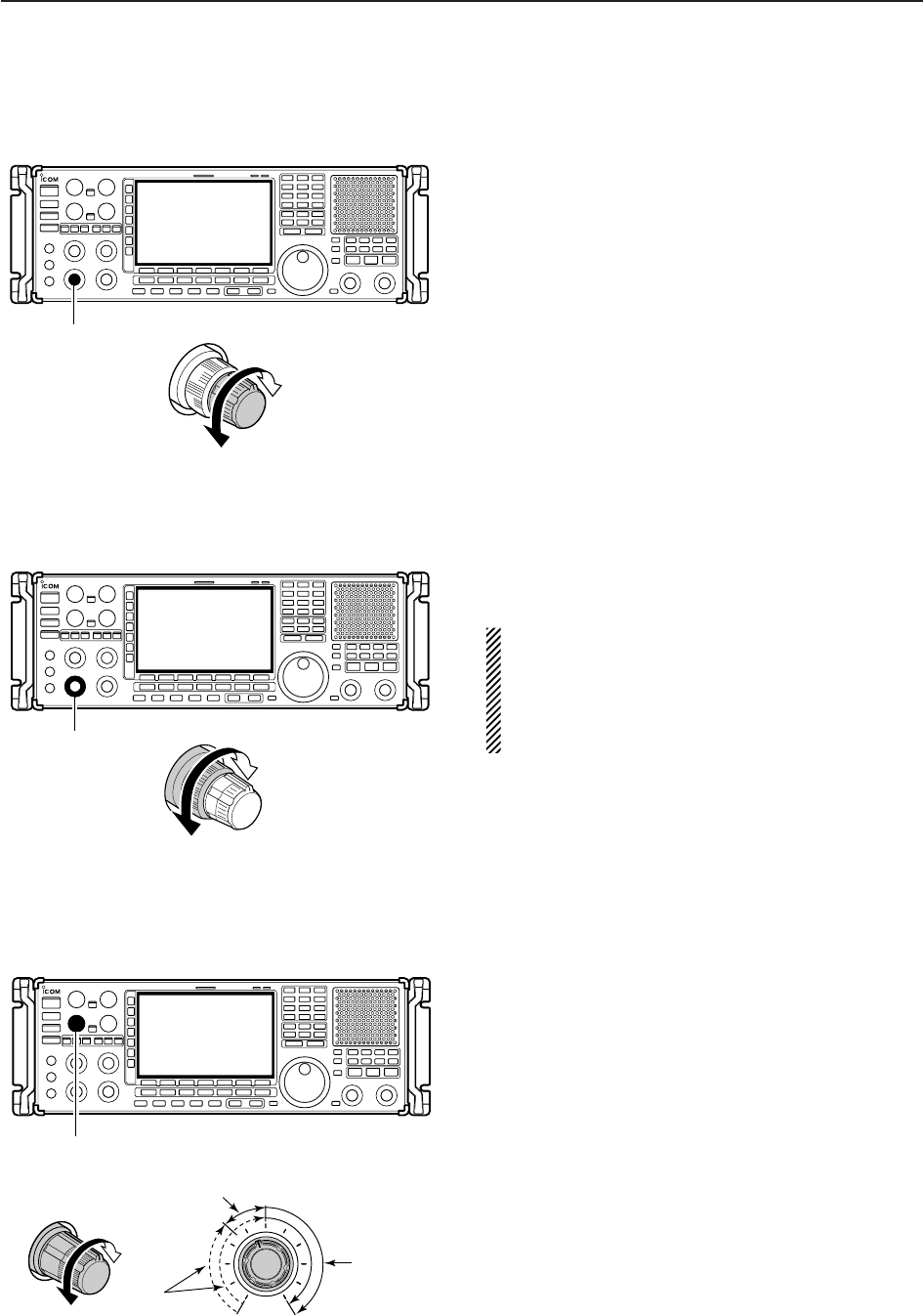
■Volume setting
➥Rotate [AF] control clockwise to increase, counter-
clockwise to decrease the audio output level.
• Set a suitable audio level.
■RF gain adjustment
➥Rotate [RF] control clockwise to increase, counter-
clockwise to decrease the receiver sensitivity.
NOTE:
• When [RF] control is adjusted CCW in FM mode,
audio output decreases then disappears. This is
normal, not a malfunction.
• When WFM mode is selected, RF gain is fixed
MAX regardless of any [RF] control settings.
■Squelch level adjustment
The squelch disables output from the speaker (closed
position) when no signal is received.
➥When no signal is received, rotate [SQUELCH] con-
trol fully counterclockwise first, then rotate
[SQUELCH] clockwise to the point that the noise
just disappears.
• Push and hold [MONI] to open the squelch temporarily.
[SQUELCH]
S-meter
squelch
Noise squelch
(Recommended level; FM/AM mode only)
Squelch is
open
Sensitivity
increases
Sensitivity
decreases
[RF]
Audio output
increases
Audio output
decreases
[AF]
3-8
3BASIC OPERATIONS
3-9
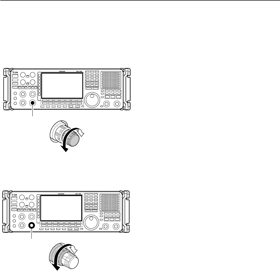
■Audio tone adjustment
DTreble level adjustment
➥Rotate [TREBLE] control clockwise to increase,
counterclockwise to decrease the treble level of the
audio tone.
DBass level adjustment
➥Rotate [BASS] control clockwise to increase, coun-
terclockwise to decrease the bass level of the audio
tone.
Tone level
increases
Tone level
decreases
[BASS]
Tone level
increases
Tone level
decreases
[TREBLE]
3
BASIC OPERATIONS
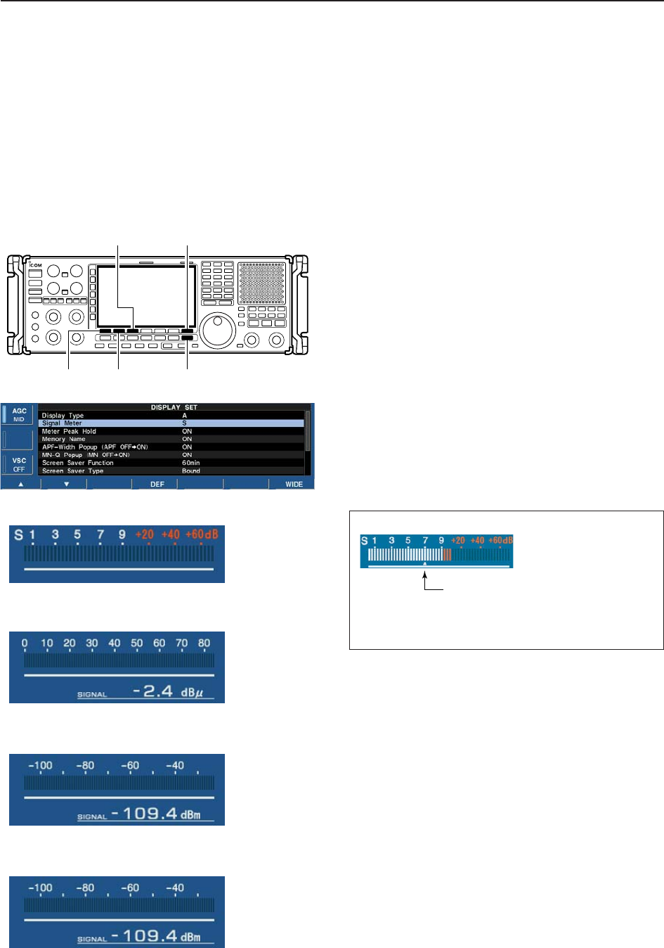
■Meter indication selection
DMeter type selection
A total of 4 meter types are available in the IC-
R9500— S-meter, dBµ, dBµ(EMF) and dBm meters.
Follow the instructions below for the meter type selec-
tion.
qPush [EXIT/SET] several times to return to normal
screen, if necessary.
wPush [F-7•SET], then push [F-3•DISPLAY] to select
the display set mode.
ePush [F-1•Y] or [F-2•Z] to select “Signal Meter”
item.
rRotate main dial to select the desired meter type
from “S,” “dBµ,” “dBµ(EMF)” and “dBm.”
tPush [EXIT/SET] to exit the display set mode.
• S meter
• dBµ meter
• dBµ[EMF] meter
• dBm meter
[F-1•Y] [F-2•Z] [EXIT/SET]
[F-7•SET][F-3•DISPLAY]
3-10
3BASIC OPERATIONS
Signal meter squelch indicator
“∫” indicates the signal meter squelch level and
appears while [SQUELCH] control is rotating.
Appears

4-1
RECEIVE MODES Section 4
■Operating FM …………………………………………………………… 4-2
DConvenient functions for FM …………………………………………4-2
■Duplex operation ……………………………………………………… 4-3
DOffset frequency setting ………………………………………………4-3
■Tone/DTCS squelch operation ………………………………………… 4-4
■Operating WFM ………………………………………………………… 4-5
DConvenient functions for WFM ………………………………………4-5
■TV channel operation ………………………………………………… 4-6
DConvenient functions for TV operation ……………………………4-6
■Operating AM …………………………………………………………… 4-7
DConvenient functions for AM …………………………………………4-7
■Operating SSB ………………………………………………………… 4-8
DConvenient functions for SSB ………………………………………4-8
■Operating CW …………………………………………………………… 4-9
DConvenient functions for CW ………………………………………4-9
DAPF (Audio Peak Filter) operation …………………………………4-10
DAbout CW reverse mode ……………………………………………4-10
DAbout CW pitch control ……………………………………………4-10
■Operating FSK ………………………………………………………… 4-11
DConvenient functions for FSK ………………………………………4-12
DAbout FSK reverse mode …………………………………………4-12
DTwin peak filter ………………………………………………………4-12
DFunctions for the FSK decoder indication …………………………4-13
DSetting the decoder threshold level ………………………………4-13
DFSK decode set mode ………………………………………………4-14
DTime stamp function …………………………………………………4-15
DSetting FSK tone frequency ………………………………………4-16
DSetting FSK Baud rate ………………………………………………4-16
DData saving …………………………………………………………4-17
■Operating P25 (Requires optional UT-122) ………………………… 4-18
DConvenient functions for P25 ………………………………………4-18
■Digital squelch operation ……………………………………………… 4-19
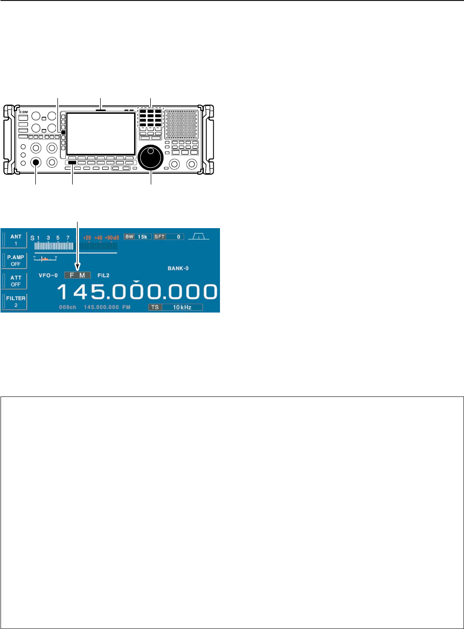
4-2
4RECEIVE MODES
■Operating FM
qEdit the desired frequency using the keypad.
wPush [FM] to select FM.
• “FM” indicator appears.
eRotate the main dial to tune the desired frequency.
• [RX] indicator lights green and the S-meter indicates re-
ceived signal strength when signal is received.
• 10 kHz tuning step is preset for the FM mode.
• Push [FILTER] several times to select the desired filter
width.
rRotate [AF] to set audio to a comfortable listening
level.
DConvenient functions for FM
Appears
Keypad[RX] indicator[FILTER]
[AF] [FM] Main dial
• Preamp (p. 5-9)
➥Push [P.AMP] several times to set the preamp
OFF, preamp 1 ON or preamp 2 ON. Only
ON/OFF is available above 30 MHz.
• “P.AMP1” or “P.AMP2” appears when the preamp 1 or
preamp 2 is ON below 30 MHz. “P.AMP ON” appears
above 30 MHz.
• Attenuator (p. 5-9)
➥Push [ATT] several times to set the attenuator in
6 dB steps for HF bands, or 10 dB step for
30–1150 MHz. Only 20 dB is available for
1150–3335 MHz.
• “ATT” and attenuation level appear when the attenu-
ator is ON.
• Auto notch filter (p. 5-16)
➥Push [NOTCH] switch to turn the auto notch func-
tion ON or OFF.
• Notch indicator (above [NOTCH] switch) lights when
either the manual notch is ON.
• VSC (voice squelch control) (p. 8-3)
➥Push [VSC] to turn the VSC function ON or OFF.
• The VSC indicator appears when the voice squelch
function is set to ON.
• AFC (Auto Frequency Control) (p. 5-17)
➥Push [AFC] to turn the AFC function ON or OFF.
• The AFC indicator appears when the AFC function is
set to ON.
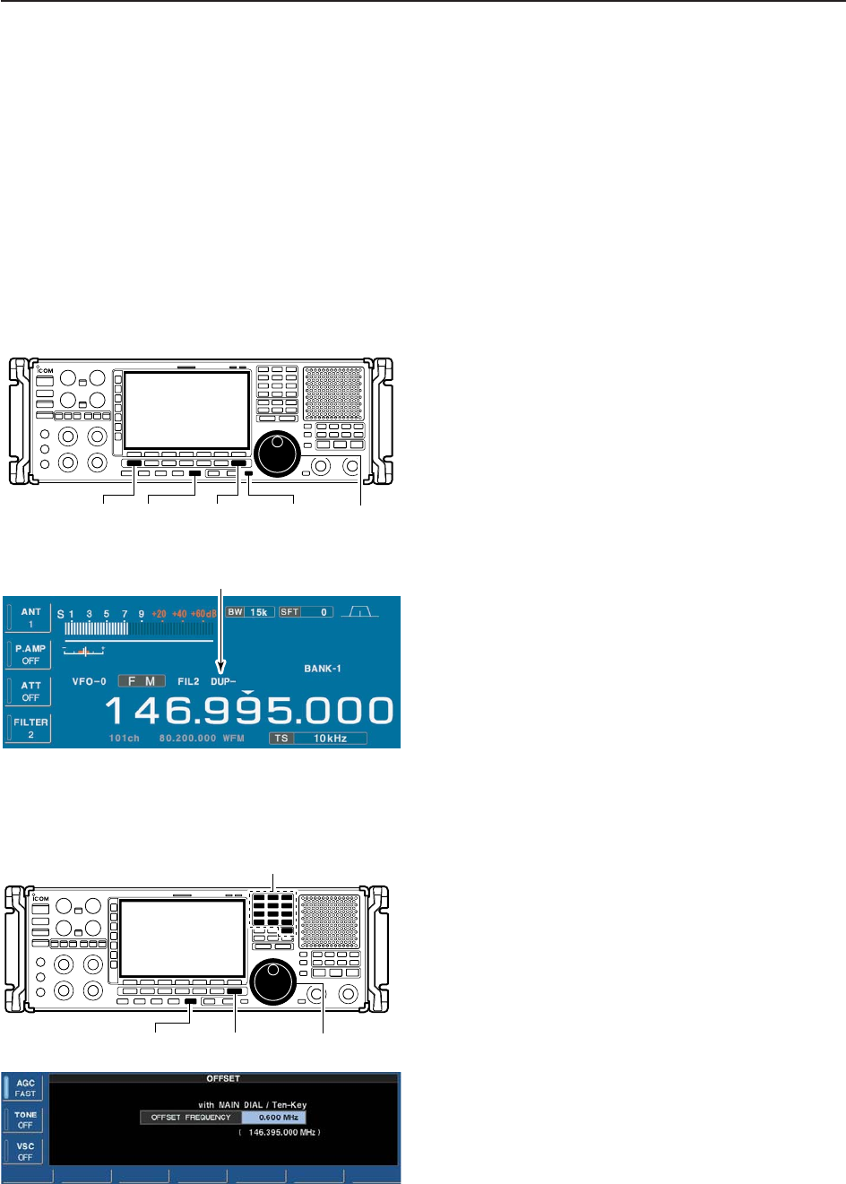
4-3
4
RECEIVE MODES
■Duplex operation
Duplex operation uses two different frequencies for
transmitting and receiving. Generally, duplex is used in
communication through a repeater, some utility com-
munications, etc.
During repeater operation, the transmit station fre-
quency is shifted from the receive station frequency by
the offset frequency. Repeater information (offset fre-
quency and shift direction) can be programmed into
memory channels.
qEdit the desired receive frequency (repeater output
frequency) using the keypad.
wPush [FM] to select FM.
• “FM” indicator appears.
ePush [DUP] several times to select the duplex di-
rection.
• “DUP–” or “DUP+” appears on the LCD.
rPush and hold [DUP] for 1 sec. to enter the offset
frequency setting screen, then rotate the main dial
to set the desired offset frequency or edit the de-
sired offset frequency directly with the keypad.
tPush and hold [MONI] to monitor the transmit sta-
tion frequency (repeater input frequency) directly.
yTo return to simplex, push [DUP] once or twice.
DOffset frequency setting
qPush and hold [DUP] for 1 sec. to enter offset fre-
quency set mode.
wRotate the main dial to select the desired offset fre-
quency or edit the desired offset frequency directly
with the keypad.
ePush [EXIT/SET] to return to the previous indica-
tion.
[EXIT/SET][DUP] Main dial
Keypad
Appears
[EXIT/SET] [MONI][FM] [DUP] Main dial
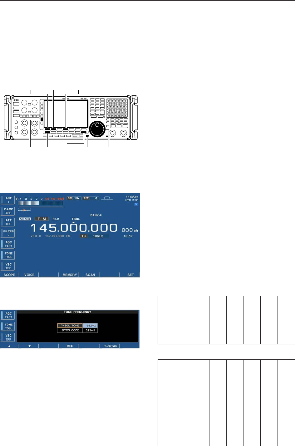
■Tone /DTCS squelch operation
The tone or DTCS squelch opens only when receiving
a signal containing a matching subaudible tone or
DTCS code. You can silently wait for calls from group
members using the same tone.
qSet the desired frequency and select FM mode.
wPush [TONE] several times to turn the tone or
DTCS squelch function ON.
• “TSQL” appears when the tone squelch function is ON.
• “DTCS” appears when the DTCS squelch function is
ON.
ePush and hold [TONE] for 1 sec. to enter tone fre-
quency set mode.
rPush [F-1•Y] or [F-2•Z] to select the items, “T-SQL
TONE” or “DTCS CODE.”
tRotate the main dial to select the desired tone fre-
quency or DTCS code.
• Push and hold [F-4•DEF] for 1 sec. to select the default
setting.
yPush [EXIT/SET] to return to the previous indica-
tion.
uWhen the received signal includes a matching tone
(or DTCS code), squelch opens and the signal can
be heard.
• When the received signal’s tone (or DTCS code) does
not match, tone (DTCS) squelch does not open, how-
ever, the S-indicator shows signal strength.
iTo open the squelch manually, push [MONI].
• The squelch opens temporarily while pushing and hold-
ing [MONI].
oTo cancel the tone squelch or DTCS squelch, push
[TONE] several times to clear the tone or DTCS
squelch.
• “TSQL” or “DTCS” disappears.
• Available tone frequencies (unit: Hz)
• Available DTCS codes
[EXIT/SET] [MONI][FM] Main dial[TONE]
[F-1•Y] [F-2•Z][F-4•DEF]
4-4
4RECEIVE MODES
67.0
69.3
71.9
74.4
77.0
79.7
82.5
085.4
088.5
091.5
094.8
097.4
100.0
103.5
107.2
110.9
114.8
118.8
123.0
127.3
131.8
136.5
141.3
146.2
151.4
156.7
159.8
162.2
165.5
167.9
171.3
173.8
177.3
179.9
183.5
186.2
189.9
192.8
196.6
199.5
203.5
206.5
210.7
218.1
225.7
229.1
233.6
241.8
250.3
254.1
150.0
023
025
026
031
032
036
043
047
051
053
054
065
071
072
073
074
114
115
116
122
125
131
132
134
143
145
152
155
156
162
165
172
174
205
212
223
225
226
243
244
245
246
251
252
255
261
263
265
266
271
274
306
311
315
325
331
332
343
346
351
356
364
365
371
411
412
413
423
431
432
445
446
452
454
455
462
464
465
466
503
506
516
523
526
532
546
565
606
612
624
627
631
632
654
662
664
703
712
723
731
732
734
743
754

4-5
4
RECEIVE MODES
■Operating WFM
qEdit the desired frequency using the keypad.
wPush [WFM] to select WFM.
• “WFM” indicator appears.
eRotate the main dial to tune the desired frequency.
• [RX] indicator lights green and the S-meter indicates re-
ceived signal strength when signal is received.
• 25 kHz tuning step is preset for the WFM mode.
rRotate [AF] to set audio to a comfortable listening
level.
DConvenient functions for WFM
Appears
Keypad[RX] indicator
[AF] [WFM] Main dial
• Preamp (p. 5-9)
➥Push [P.AMP] several times to set the preamp
OFF, preamp 1 ON or preamp 2 ON. Only
ON/OFF is available above 30 MHz.
• “P.AMP1” or “P.AMP2” appears when the preamp 1 or
preamp 2 is ON below 30 MHz. “P.AMP ON” appears
above 30 MHz.
• Attenuator (p. 5-9)
➥Push [ATT] several times to set the attenuator in
6 dB steps for HF bands, or 10 dB step for
30–1150 MHz. Only 20 dB is available for
1150–3335 MHz.
• “ATT” and attenuation level appear when the attenu-
ator is ON.
• Auto notch filter (p. 5-16)
➥Push [NOTCH] switch to turn the auto notch func-
tion ON or OFF.
• Notch indicator (above [NOTCH] switch) lights when
either the manual notch is ON.
• VSC (voice squelch control) (p. 8-3)
➥Push [VSC] to turn the VSC function ON or OFF.
• The VSC indicator appears when the voice squelch
function is set to ON.
• AFC (Auto Frequency Control) (p. 5-17)
➥Push [AFC] to turn the AFC function ON or OFF.
• The AFC indicator appears when the AFC function is
set to ON.
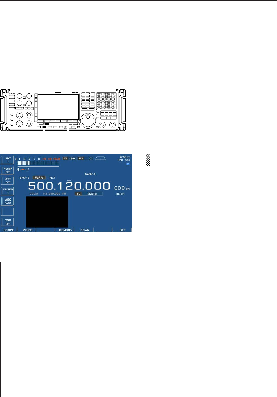
4-6
4RECEIVE MODES
■TV channel operation
A TV tuner is built-in to the IC-R9500, and connects to
the [VIDEO IN] and [VIDEO OUT] on the rear panel
using a TV jumper cable to monitor the TV programs.
If you would rather use your TV tuner, connect the ex-
ternal tuner to [VIDEO IN] on the rear panel.
qPush [DISPLAY] once or twice to turn ON the de-
sired TV screen.
• Push once to turn ON the mini TV screen, push again
to turn ON the full TV screen and push again to close
the TV screen.
wSet the desired frequency and select WFM mode.
ePush [DISPLAY] to close the TV screen.
The TV display settings can be adjusted in display
set (Video) mode. (p. 11-24)
DConvenient functions for TV operation
[DISPLAY] [WFM]
• Preamp (p. 5-9)
➥Push [P.AMP] several times to set the preamp
OFF, preamp 1 ON or preamp 2 ON. Only
ON/OFF is available above 30 MHz.
• “P.AMP1” or “P.AMP2” appears when the preamp 1 or
preamp 2 is ON below 30 MHz. “P.AMP ON” appears
above 30 MHz.
• Attenuator (p. 5-9)
➥Push [ATT] several times to set the attenuator in
6 dB steps for HF bands, or 10 dB step for
30–1150 MHz. Only 20 dB is available for
1150–3335 MHz.
• “ATT” and attenuation level appear when the attenu-
ator is ON.
• Auto notch filter (p. 5-16)
➥Push [NOTCH] switch to turn the auto notch func-
tion ON or OFF.
• Notch indicator (above [NOTCH] switch) lights when
either the manual notch is ON.
• VSC (voice squelch control) (p. 8-3)
➥Push [VSC] to turn the VSC function ON or OFF.
• The VSC indicator appears when the voice squelch
function is set to ON.
• AFC (Auto Frequency Control) (p. 5-17)
➥Push [AFC] to turn the AFC function ON or OFF.
• The AFC indicator appears when the AFC function is
set to ON.
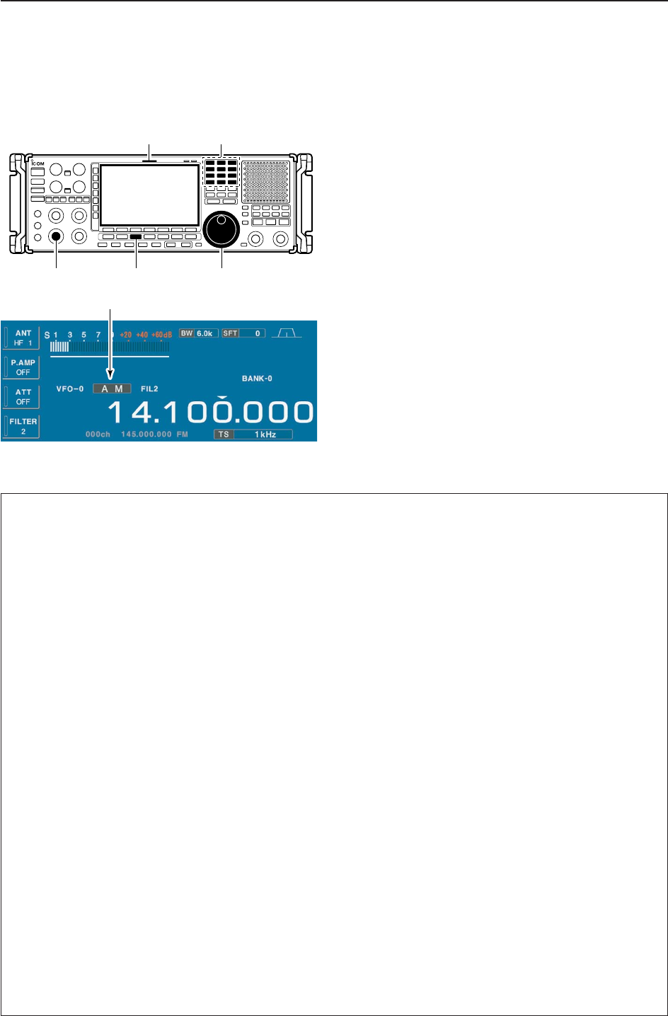
4-7
4
RECEIVE MODES
■Operating AM
qEdit the desired frequency using the keypad.
wPush [AM] to select AM.
• “AM” indicator appears.
• After AM mode is selected, push and hold [AM] for 1
sec. to toggle between AM and S-AM modes.
eRotate the main dial to tune the desired frequency.
• [RX] indicator lights green and the S-meter indicates re-
ceived signal strength when signal is received.
rRotate [AF] to set audio to a comfortable listening
level.
DConvenient functions for AM
Appears
Keypad[RX] indicator
[AF] [AM] Main dial
• Preamp (p. 5-9)
➥Push [P.AMP] several times to set the preamp
OFF, preamp 1 ON or preamp 2 ON. Only
ON/OFF is available above 30 MHz.
• “P.AMP1” or “P.AMP2” appears when the preamp 1 or
preamp 2 is ON below 30 MHz. “P.AMP ON” appears
above 30 MHz.
• Attenuator (p. 5-9)
➥Push [ATT] several times to set the attenuator in
6 dB steps for HF bands, or 10 dB step for
30–1150 MHz. Only 20 dB is available for
1150–3335 MHz.
• “ATT” and attenuation level appear when the attenu-
ator is ON.
• Noise blanker (p. 5-15)
➥Push [NB] switch to turn the noise blanker ON
and OFF, and then rotate [NB] control to adjust
the threshold level.
• Noise blanker indicator (above [NB] switch) lights
when the noise blanker is ON.
• Push [NB] for 1 sec. to enter noise blanker set mode.
• Noise reduction (p. 5-16)
➥Push [NR] switch to turn the noise reduction ON
and OFF.
• Rotate [NR] control to adjust the noise reduction
level.
• Noise reduction indicator (above [NR] switch) lights
when the noise reduction is ON.
• Twin PBT (passband tuning) (p. 5-11)
➥Rotate [TWIN PBT] controls (inner/outer).
• Push [PBT CLEAR] to clear the settings.
• Auto notch filter (p. 5-16)
➥Push [ANF] switch to turn the auto notch function
ON or OFF.
• Notch indicator (above [ANF] switch) lights when the
auto notch is ON.
• Manual notch filter (p. 5-16)
➥Push [NOTCH1] or [NOTCH2] switch to turn the
manual notch function ON or OFF.
• Rotate [NOTCH] control to set the notch frequency.
• Notch indicator (above [NOTCH1] or [NOTCH2]
switch) lights when either the manual notch is ON.
• AGC (auto gain control) (p. 5-10)
➥Push [AGC] switch several times to select
AGC FAST, AGC MID or AGC SLOW.
➥Push [AGC VR] to turn the AGC time constant
manual setting ON or OFF.
• Rotate [AGC] control to adjust the time constant.
• Auto tuning function (p. 5-17)
➥Push [AUTOTUNE] to turn the auto tuning func-
tion ON or OFF.
• The receiver automatically tunes the desired signal
within ±5 kHz range.
IMPORTANT!
When receiving a weak signal, or receiving a signal
with interference, the automatic tuning function may
not tune, or may tune to an undesired signal.
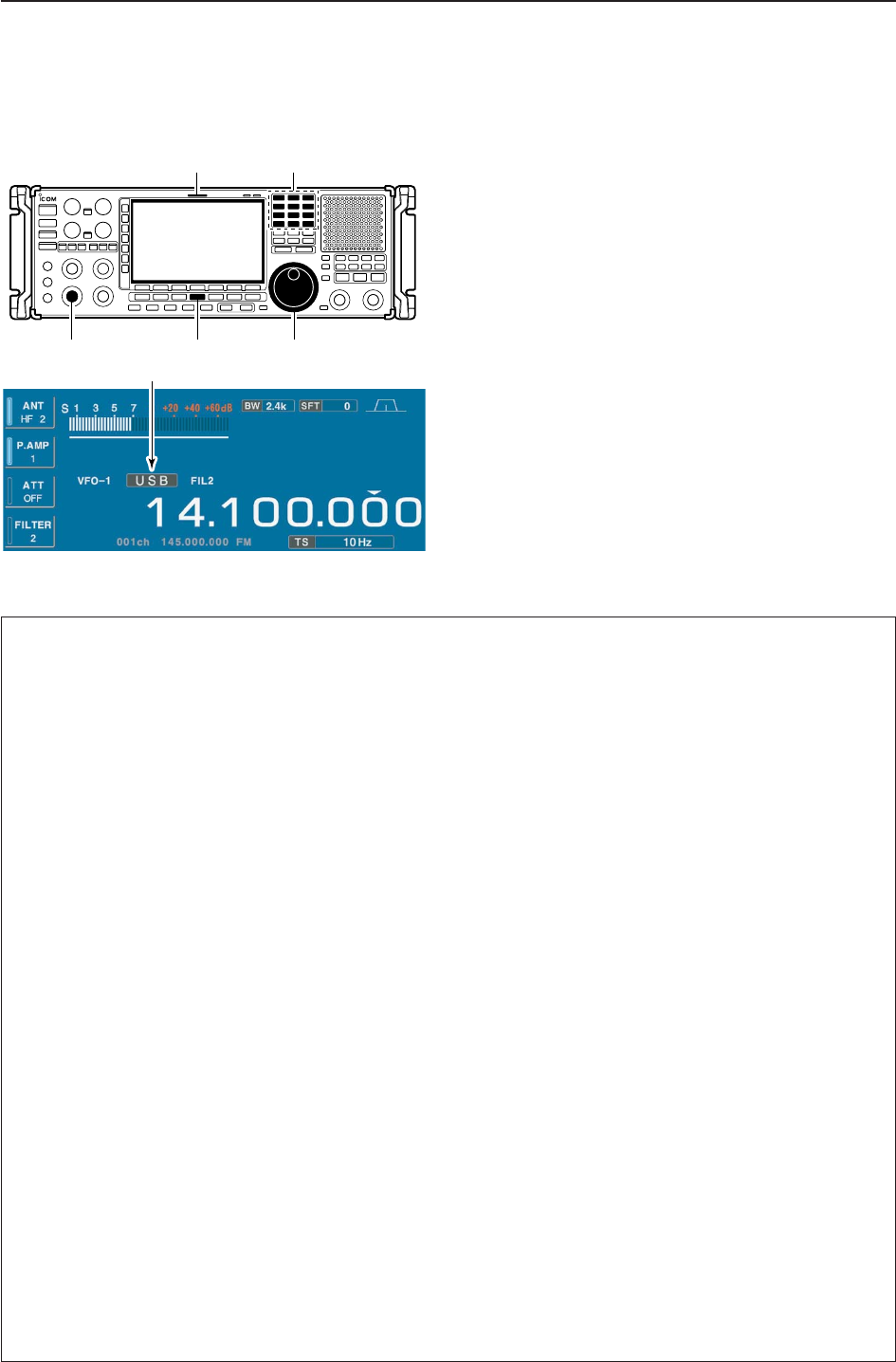
4-8
■Operating SSB
qEdit the desired frequency using the keypad.
wPush [SSB/CW] to select SSB (LSB or USB).
• After SSB mode is selected, push and hold [SSB/CW]
for 1 sec. to toggle between LSB and USB modes.
• “LSB” or “USB” appears.
eRotate the main dial to tune a desired signal.
• [RX] indicator lights green and the S-meter indicates re-
ceived signal strength when signal is received.
rRotate [AF] to set audio to a comfortable listening
level.
DConvenient functions for SSB
Appears
Keypad[RX] indicator
[AF] [SSB/CW] Main dial
4RECEIVE MODES
• Preamp (p. 5-9)
➥Push [P.AMP] several times to set the preamp
OFF, preamp 1 ON or preamp 2 ON. Only
ON/OFF is available above 30 MHz.
• “P.AMP1” or “P.AMP2” appears when the preamp 1 or
preamp 2 is ON below 30 MHz. “P.AMP ON” appears
above 30 MHz.
• Attenuator (p. 5-9)
➥Push [ATT] several times to set the attenuator in
6 dB steps for HF bands, or 10 dB step for
30–1150 MHz. Only 20 dB is available for
1150–3335 MHz.
• “ATT” and attenuation level appear when the attenu-
ator is ON.
• Noise blanker (p. 5-15)
➥Push [NB] switch several times to select the
noise blanker 1 ON, noise blanker 2 ON and
noise blanker OFF, and then rotate [NB] control to
adjust the threshold level.
• Noise blanker indicator (above [NB] switch) lights
when the noise blanker is ON.
• Push [NB] for 1 sec. to enter noise blanker set mode.
• Twin PBT (passband tuning) (p. 5-11)
➥Rotate [TWIN PBT] controls.
• Push [PBT CLEAR] to clear the settings.
• Noise reduction (p. 5-16)
➥Push [NR] switch to turn the noise reduction ON
and OFF.
• Rotate [NR] control to adjust the noise reduction
level.
• Noise reduction indicator (above [NR] switch) lights
when the noise reduction is ON.
• Auto notch filter (p. 5-16)
➥Push [ANF] switch to turn the auto notch function
ON or OFF.
• Notch indicator (above [ANF] switch) lights when the
auto notch is ON.
• Manual notch filter (p. 5-16)
➥Push [NOTCH1] or [NOTCH2] switch to turn the
manual notch function ON or OFF.
• Rotate [NOTCH] control to set the attenuating fre-
quency.
• Notch indicator (above [NOTCH1] or [NOTCH2]
switch) lights when either the manual notch is ON.
• AGC (auto gain control) (p. 5-10)
➥Push [AGC] switch several times to select
AGC FAST, AGC MID or AGC SLOW.
➥Push [AGC VR] to turn the AGC time constant
manual setting ON or OFF.
• Rotate [AGC] control to adjust the time constant.
• VSC (voice squelch control) (p. 8-3)
➥Push [VSC] to turn the VSC function ON or OFF.
• The VSC indicator appears when the voice squelch
function is set to ON.
• Auto tuning function (p. 5-17)
➥Push [AUTOTUNE] to turn the auto tuning func-
tion ON or OFF.
• The receiver automatically tunes the desired signal
within ±5 kHz range.
IMPORTANT!
When receiving a weak signal, or receiving a signal
with interference, the automatic tuning function may
not tune, or may tune to an undesired signal.
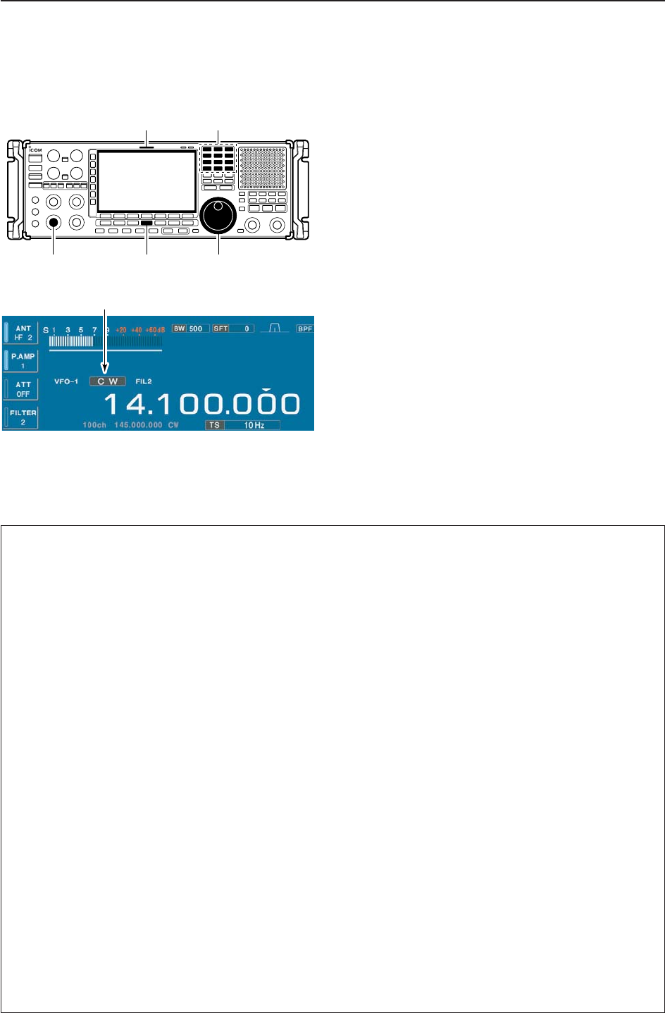
4-9
4
RECEIVE MODES
■Operating CW
qEdit the desired frequency using the keypad.
wPush [SSB/CW] to select CW.
• After CW mode is selected, push and hold [SSB/CW] for
1 sec. to toggle between CW and CW-R modes.
• “CW” or “CW-R” appears.
eRotate the main dial to tune a desired signal.
• Try to match the specified signal’s tone to the side tone
frequency.
• [RX] indicator lights green and the S-meter indicates re-
ceived signal strength when signal is received.
rRotate [AF] to set audio to a comfortable listening
level.
DConvenient functions for CW
Appears
Keypad[RX] indicator
[AF] [SSB/CW] Main dial
• Preamp (p. 5-9)
➥Push [P.AMP] several times to set the preamp
OFF, preamp 1 ON or preamp 2 ON. Only
ON/OFF is available above 30 MHz.
• “P.AMP1” or “P.AMP2” appears when the preamp 1 or
preamp 2 is ON below 30 MHz. “P.AMP ON” appears
above 30 MHz.
• Attenuator (p. 5-9)
➥Push [ATT] several times to set the attenuator in
6 dB steps for HF bands, or 10 dB step for
30–1150 MHz. Only 20 dB is available for
1150–3335 MHz.
• “ATT” and attenuation level appear when the attenu-
ator is ON.
• Noise blanker (p. 5-15)
➥Push [NB] switch to turn the noise blanker ON
and OFF, and then rotate [NB] control to adjust
the threshold level.
• Noise blanker indicator (above [NB] switch) lights
when the noise blanker is ON.
• Push [NB] for 1 sec. to enter noise blanker set mode.
• Noise reduction (p. 5-16)
➥Push [NR] switch to turn the noise reduction ON
and OFF.
• Rotate [NR] control to adjust the noise reduction
level.
• Noise reduction indicator (above [NR] switch) lights
when the noise reduction is ON.
• Twin PBT (passband tuning) (p. 5-11)
➥Rotate [TWIN PBT] controls (inner/outer).
• Push [PBT CLEAR] to clear the settings.
• Manual notch filter (p. 5-16)
➥Push [NOTCH1] or [NOTCH2] switch to turn the
manual notch function ON or OFF.
• Rotate [NOTCH] control to set the notch frequency.
• Notch indicator (above [NOTCH1] or [NOTCH2]
switch) lights when either the manual notch is ON.
• AGC (auto gain control) (p. 5-10)
➥Push [AGC] switch several times to select
AGC FAST, AGC MID or AGC SLOW.
➥Push [AGC VR] to turn the AGC time constant
manual setting ON or OFF.
• Rotate [AGC] control to adjust the time constant.
•1⁄4function (p. 3-6)
➥Push [1/4] to turn the 1⁄4function ON or OFF.
• Auto tuning function (p. 5-17)
➥Push [AUTOTUNE] to turn the auto tuning func-
tion ON or OFF.
• The receiver automatically tunes the desired signal
within a ±500 Hz range.
IMPORTANT!
When receiving a weak signal, or receiving a signal
with interference, the automatic tuning function may
not tune properly, or tune onto an undesired signal.
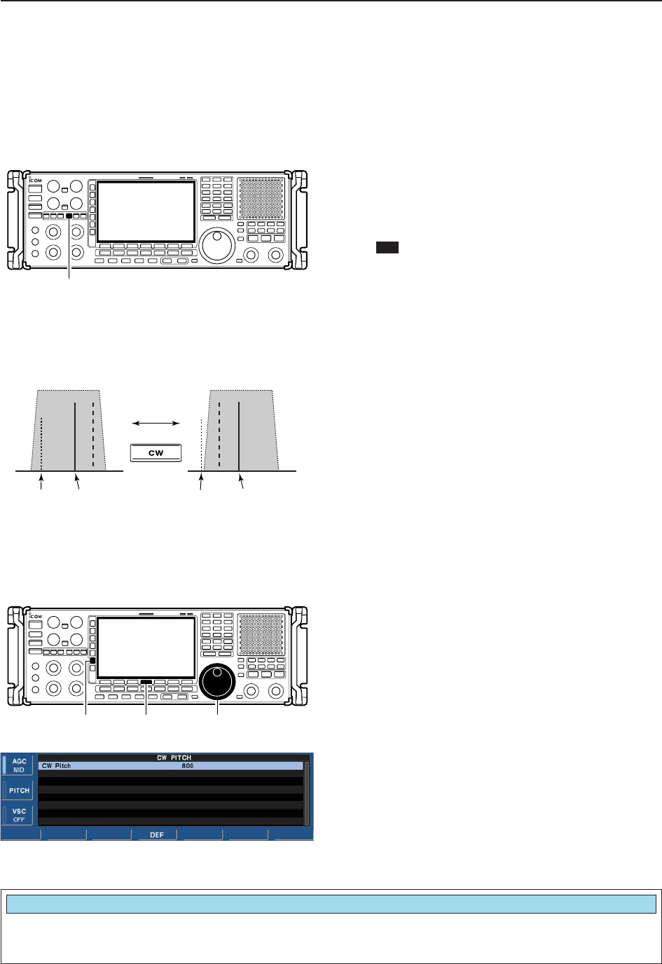
4-10
4RECEIVE MODES
DAPF (Audio Peak Filter) operation
The APF changes the audio frequency response by
boosting a particular frequency to enhance a desired
CW signal.
The audio filter shape is also selectable from “SOFT”
and “SHARP” in the others set mode. (p. 11-13)
qDuring CW mode, push [APF/TPF] to turn the audio
peak filter ON and OFF.
• “ ” appears in the display and [APF/TPF] indicator
above this switch lights green.
wPush and hold [APF/TPF] for 1 sec. several times
to select the desired audio filter width.
• 320, 160 and 80 Hz filters are available.
DAbout CW reverse mode
CW-R (CW Reverse) mode uses the opposite side
band to receive CW signals.
Use when interfering signals are near a desired signal
and you want to use CW-R to reduce the interference.
➥During CW mode, push and hold [SSB/CW] for 1
sec. to select CW and CW-R mode.
DAbout CW pitch control
The received CW audio pitch can be adjusted to suit
your preference (from 300 to 900 Hz in 5 Hz steps).
This does not change the operating frequency.
qDuring CW mode, push [PITCH] to turn the CW
pitch setting screen ON and OFF.
wRotate the main dial to suit your preference.
• Adjustable within 300 to 900 Hz in 5 Hz steps.
• Push and hold [F-4•DEF] for 1 sec. to return to the de-
fault setting.
[PITCH] [F-4•DEF] Main dial
Push
BFO
CW-R mode (USB side)
BFO
Desired signal
CW mode (LSB side)
Interference Desired signalInterference
APF
[APF/TPF]
Sets the desired CW pitch within 300 to 900 Hz in
5 Hz steps. (default: 800 Hz)
CW Pitch
800
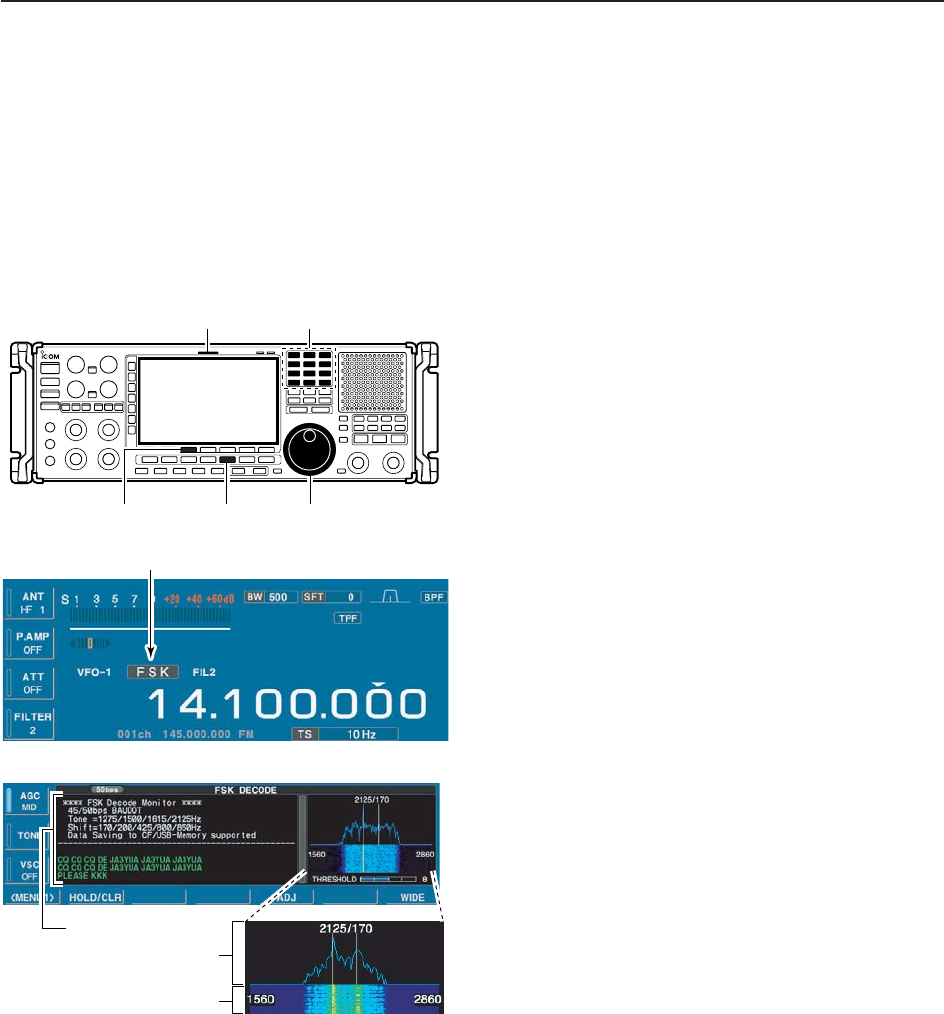
4-11
4
RECEIVE MODES
■Operating FSK
A DSP-based high-quality Baudot FSK decoder is built-
in to the IC-R9500.
If you would rather use your FSK terminal or TNC, con-
sult the manual that comes with the FSK terminal or
TNC.
qEdit the desired frequency using the keypad.
wPush [FSK] to select FSK.
• After FSK mode is selected, push and hold [FSK] for
1 sec. to toggle between FSK and FSK-R modes.
• “FSK” or “FSK-R” appears.
ePush [F-3•DECODE] to display the decoder screen.
• The IC-R9500 has a built-in Baudot decoder.
rTo tune the desired signal, aim for a symmetrical
wave form and ensure the signal peaks align with
the mark (2125 Hz) and shift (170 Hz) frequency
lines in the FFT scope.
• [RX] indicator lights green and the S-meter indicates re-
ceived signal strength when signal is received.
FFT scope
RX contents screen
Water-fall
Appears
Keypad[RX] indicator
[F-3•DECODE] [FSK] Main dial
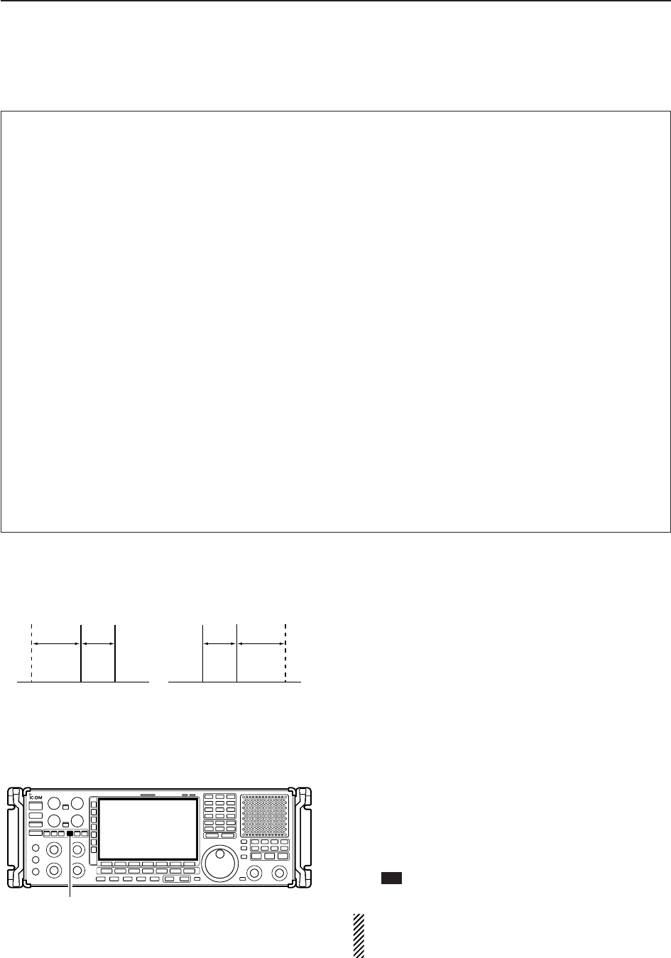
4-12
4RECEIVE MODES
DConvenient functions for FSK
DAbout FSK reverse mode
Received characters are occasionally garbled when
the received signal has Mark and Space tones re-
versed. This reversal can be caused by incorrect TNC
connections, setting, commands, etc. To receive re-
versed FSK signals correctly, select FSK-R mode.
➥During FSK mode, push and hold [FSK] for 1 sec.
to select FSK and FSK-R mode.
DTwin peak filter
The twin peak filter changes audio frequency response
by boosting the mark and space frequencies (2125 and
2295 Hz) for better reception of FSK signals.
➥During FSK mode, push [APF/TPF] to turn the twin
peak filter ON and OFF.
• “ ” appears in the LCD and the [APF/TPF] indicator
above this switch lights green while the filter is in use.
NOTE: When the twin peak filter is in use, the re-
ceived audio output may increase. This is normal,
not a malfunction.
TPF
[APF/TPF]
FSK FSK-R
f1 f2
BFO
f1 f2
BFO
SHIFT TONESHIFTTONE
• Preamp (p. 5-9)
➥Push [P.AMP] several times to set the preamp
OFF, preamp 1 ON or preamp 2 ON. Only
ON/OFF is available above 30 MHz.
• “P.AMP1” or “P.AMP2” appears when the preamp 1 or
preamp 2 is ON below 30 MHz. “P.AMP ON” appears
above 30 MHz.
• Attenuator (p. 5-9)
➥Push [ATT] several times to set the attenuator in
6 dB steps for HF bands, or 10 dB step for
30–1150 MHz. Only 20 dB is available for
1150–3335 MHz.
• “ATT” and attenuation level appear when the attenu-
ator is ON.
• Noise blanker (p. 5-15)
➥Push [NB] switch to turn the noise blanker ON
and OFF, and then rotate [NB] control to adjust
the threshold level.
• Noise blanker indicator (above [NB] switch) lights
when the noise blanker is ON.
• Push [NB] for 1 sec. to enter noise blanker set mode.
• Twin PBT (passband tuning) (p. 5-11)
➥Rotate [TWIN PBT] controls (inner/outer).
• Push [PBT CLEAR] to clear the settings.
• Noise reduction (p. 5-16)
➥Push [NR] switch to turn the noise reduction ON
and OFF.
• Rotate [NR] control to adjust the noise reduction
level.
• Noise reduction indicator (above [NR] switch) lights
when the noise reduction is ON.
• Manual notch filter (p. 5-16)
➥Push [NOTCH1] or [NOTCH2] switch to turn the
manual notch function ON or OFF.
• Rotate [NOTCH] control to set the notch frequency.
• Notch indicator (above [NOTCH1] or [NOTCH2]
switch) lights when either the manual notch is ON.
• AGC (auto gain control) (p. 5-10)
➥Push [AGC] switch several times to select
AGC FAST, AGC MID or AGC SLOW.
➥Push [AGC VR] to turn the AGC time constant
manual setting ON or OFF.
• Rotate [AGC] control to adjust the time constant.
•1⁄4function (p. 3-6)
➥Push [1/4] to turn the 1⁄4function ON or OFF.
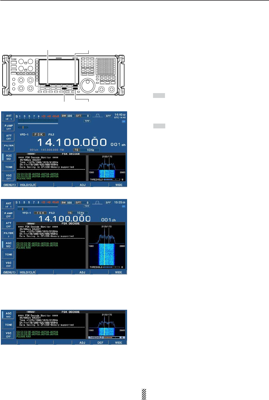
4-13
4
RECEIVE MODES
DFunctions for the FSK decoder indication
qPush [FSK] to select FSK.
• After FSK mode is selected, push and hold [FSK] for
1 sec. to toggle between FSK and FSK-R modes.
• “FSK” or “FSK-R” appears.
wPush [F-3•DECODE] to display the decoder screen.
• When tuned into an FSK signal, decoded characters are
displayed in the contents screen.
ePush [F-2•HOLD/CLR] to freeze the current screen.
• “ ” appears while the function is in use.
• Push [F-2•HOLD/CLR] again to release the function.
rPush and hold [F-2•HOLD/CLR] for 1 sec. to clear
the displayed characters.
•“ ” indicator disappears at the same time when the
hold function is in use.
tPush [F-7•WIDE] to toggle the FSK decode screen
size from normal and wide.
yPush [EXIT/SET] to close the FSK decode screen.
• Wide screen indication
DSetting the decoder threshold level
Adjust the FSK decoder threshold level if some char-
acters are displayed when no signal is received.
qSelect the FSK decoder screen as described above.
wPush [F-5•ADJ] to select the threshold level setting
condition.
eRotate the main dial to adjust the FSK decoder
threshold level.
• Push and [F-6•DEF] for 1 sec. to select the default set-
ting.
rPush [F-5•ADJ] to exit from the threshold level set-
ting condition.
The UnShift On Space (USOS) function and new
line code can be set in the FSK set mode. (p. 4-14)
HOLD
HOLD
[EXIT/SET][FSK]
[F-2•HOLD/CLR] [F-7•WIDE]
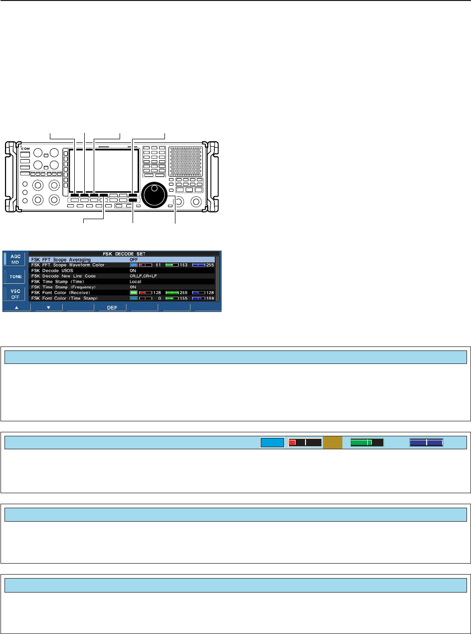
4-14
4RECEIVE MODES
DFSK decode set mode
This set mode is used to set the decode USOS func-
tion, time stamp setting, etc.
• Setting contents
qDuring FSK mode operation, push [F-3•DECODE]
to select FSK decode screen.
wPush [F-1•MENU1] to select FSK decode menu
2, then push [F-6•SET] to select FSK decode set
mode.
• Push [F-7•WIDE] to toggle the screen size from normal
and wide.
ePush [F-1•Y] or [F-2•Z] to select the desired set
item.
rSet the desired condition using the main dial.
• Push and hold [F-4•DEF] for 1 sec. to select a default
condition or value.
• Push [F-3•Ω≈] to select the set contents for some
items.
tPush [EXIT/SET] to exit from set mode.
[EXIT/SET] Main dial
[F-1•Y] [F-2•Z][F-3•Ω ≈]
[F-4•DEF]
[F-7•WIDE]
• FSK decode set mode screen
Turn letter code decoding after receiving a “space”
(USOS; UnShift On Space function) capability ON
and OFF.
• ON : Decode as letter code.
• OFF : Decode as character code.
Selects the new line code of the internal FSK de-
coder.
CR: Carriage Return, LF: Line Feed
• CR,LF,CR;LF : Makes new line with any codes.
• CR+LF : Makes new line with CR+LF code
only.
FSK Decode USOS
ON
FSK Decode New Line Code
CR,LF,CR+LF
Set the FFT scope waveform averaging function from
2 to 4 and OFF. (default: OFF) Recommendation!
If you use the FFT scope waveform for tuning, use of
the default, or smaller number setting is recom-
mended.
FSK FFT Scope Averaging
OFF
Set the color for the FFT scope waveform.
• The color is set in RGB format.
• The set color is indicated in the box beside the RGB scale.
• Push [F-3•Ω≈] to select R (Red), G (Green) and B (Blue),
and then rotate the main dial to set the ratio from 0 to 255.
FSK FFT Scope Waveform Color
51 153 255
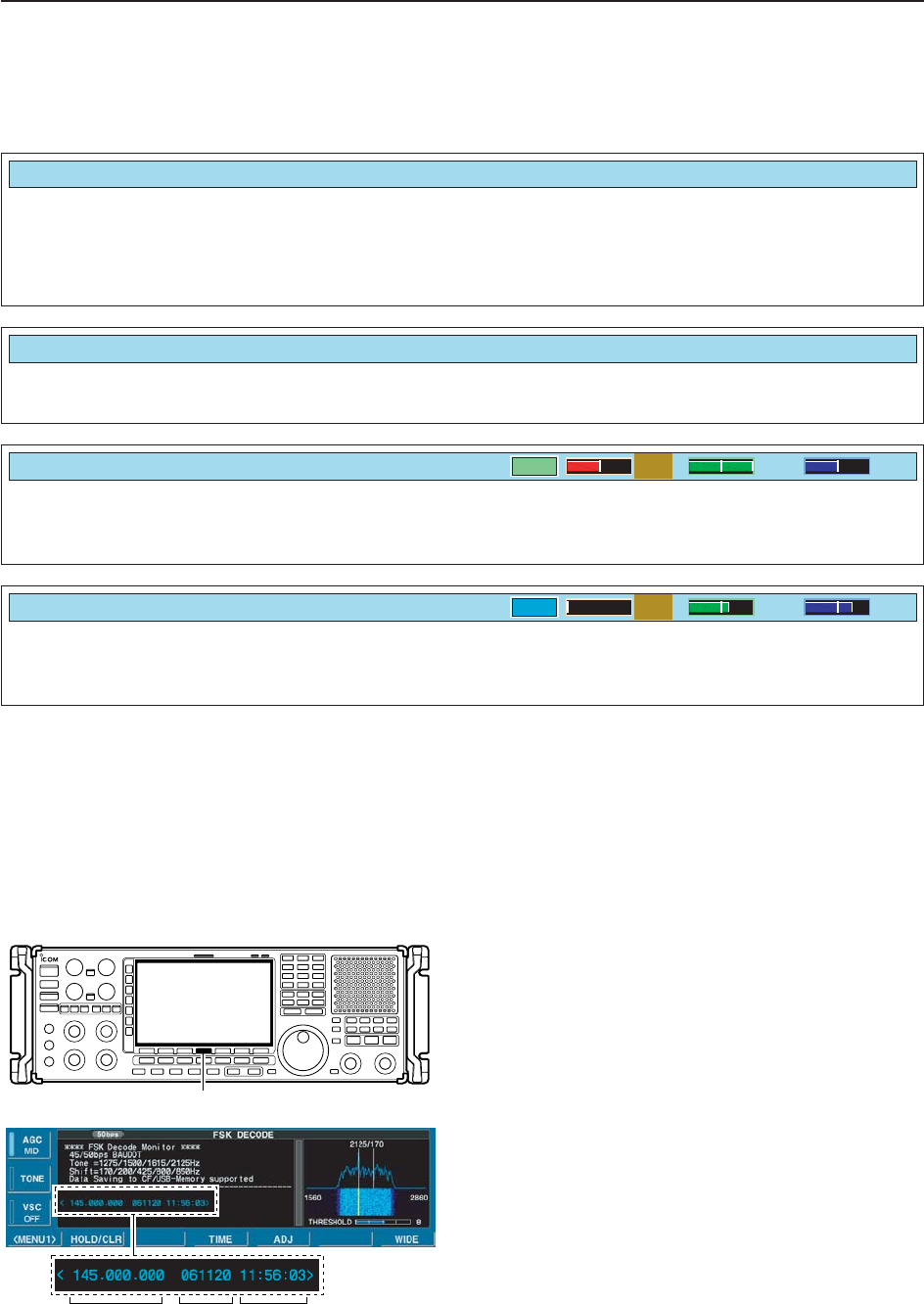
4-15
4
RECEIVE MODES
DFSK decode set mode (continued)
Selects the clock indication for time stamp usage.
NOTE: The time will be displayed when [F-4•TIME] is
pushed in “FSK DECODE” screen as at page
4-13.
• Local : Selects the time that set in “Time (Now).”
• UTC* : Selects the time that set in “CLOCK2.”
*The name of choice may differ according to
“CLOCK2 Name” setting (p, 10-2). “UTC” is the
default name of CLOCK2.
FSK Time Stamp (Time)
Local
Selects the operating frequency indication for time
stamp usage. • ON : Displays the operating frequency. (default)
• OFF : No operating frequency displays.
Set the text color for received characters.
• The color is set in RGB format.
• The set color is indicated in the box beside the RGB scale.
• Push [F-3•Ω≈] to select R (Red), G (Green) and B (Blue),
and then rotate the main dial to set the ratio from 0 to 255.
FSK Time Stamp (Frequency)
ON
FSK Font Color (Receive)
128 255 128
Set the text color for time stamp indication.
• The color is set in RGB format.
• The set color is indicated in the box beside the RGB scale.
• Push [F-3•Ω≈] to select R (Red), G (Green) and B (Blue),
and then rotate the main dial to set the ratio from 0 to 255.
FSK Font Color (Time Stamp)
0155 189
DTime stamp function
Time stamp function is used to add the time or fre-
quency information when receiving a signal. Frequency
information can be turned OFF in FSK decode set
mode.
qSelect the FSK decoder screen as described on
page 4-13.
wPush [F-4•TIME] to add the time stamp information.
• Frequency , date and time information are added on the
decoder screen.
eContinue receiving.
Frequency Date Time
[F-4•TIME]
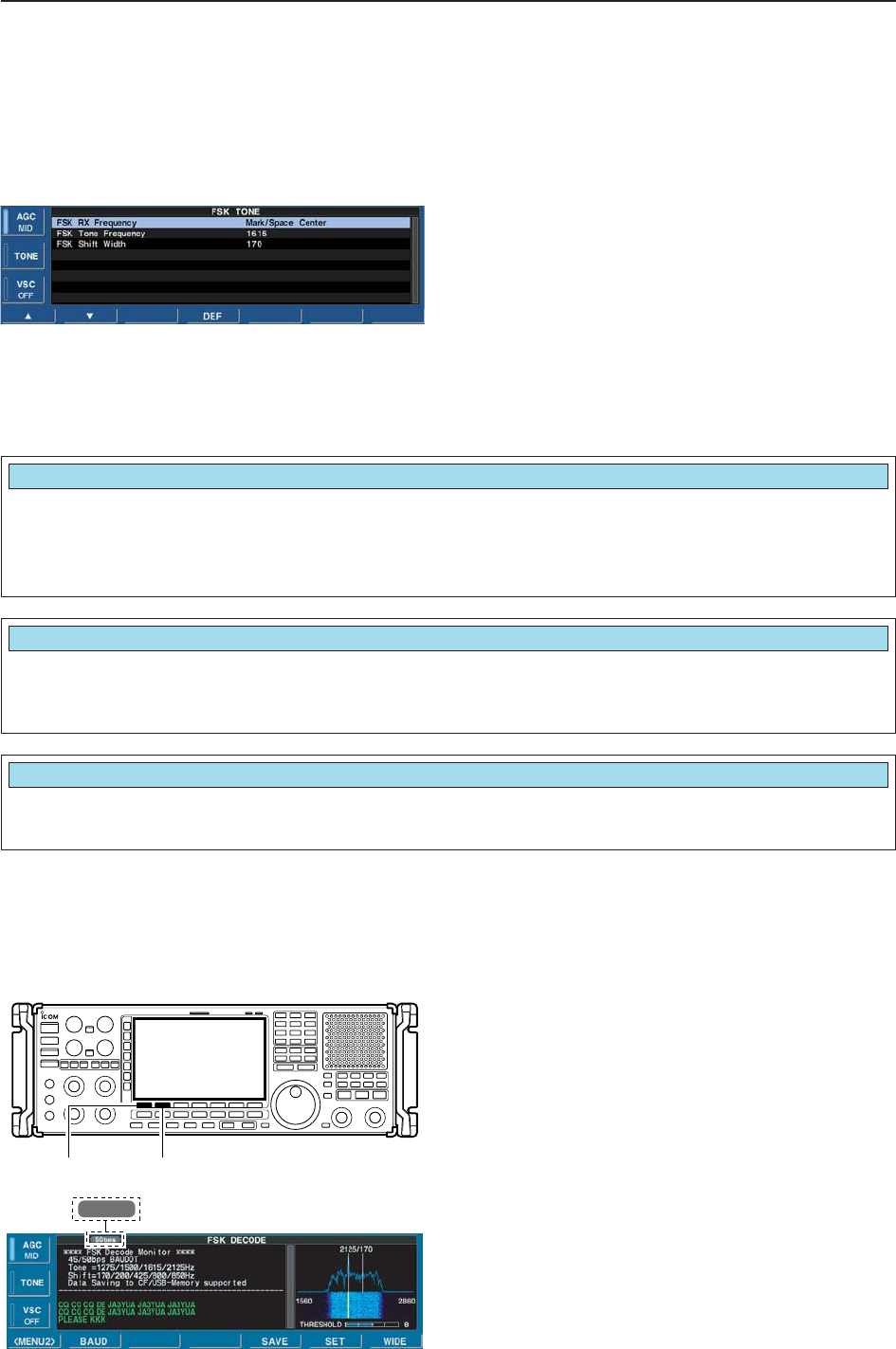
4-16
4RECEIVE MODES
Selects the FSK mark frequency. FSK mark frequency
is switched between 1275, 1615 and 2125 Hz.
(default: 2125 Hz)
FSK Tone Frequency
2125
Selects the FSK shift width. There are 3 selectable
values: 170, 200 and 425 Hz. (default: 170 Hz)
FSK Shift Width
170
DSetting FSK tone frequency
Select the FSK tone frequency and adjust the FSK shift
width.
qSelect the FSK decoder screen as described on
page 4-13.
wPush [TONE] on the multifunction menu to enter
FSK tone set mode.
ePush [F-1•Y] or [F-2•Z] to select the items, “FSK
Tone Frequency” or “FSK Shift Width.”
rRotate the main dial to select the desired tone fre-
quency or shift width.
• Push and hold [F-4•DEF] for 1 sec. to select the default
setting.
tPush [EXIT/SET] to return to the previous indication.
DSetting FSK baud rate
The data transfer rate can be selected from two
speeds, 45 bps and 50 bps.
qSelect the FSK decoder screen as described on
page 4-13.
wPush [F-1•MENU1] to select the second FSK de-
code menu.
ePush [F-2•BAUD] to select the desired data trans-
fer rate.
• 45 bps and 50 bps are available.
50 bps Selected baud rate appears
[F-1•MENU1][F-2•BAUD]
Selects the FSK receive frequency from Mark/Space
Center and Mark(Space).
(default: Mark/Space Center)
• Mark/Space Center: Displayed frequency is set to
the center of Mark and Space.
• Mark(Space): Displayed frequecy is set as Mark
(FSK mode) or Space (FSK-R mode).
FSK RX Frequency
Mark/Space Center
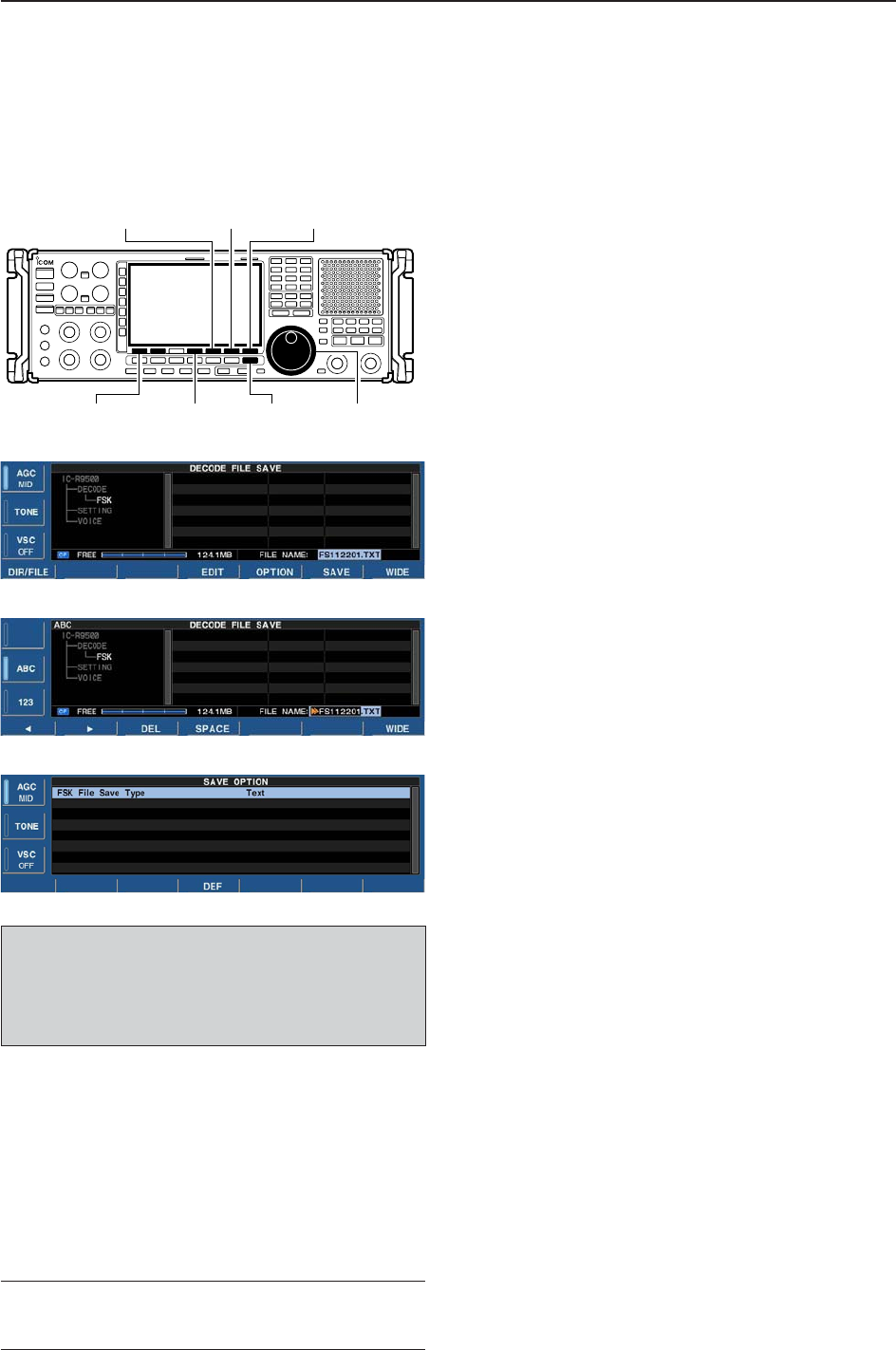
4-17
4
RECEIVE MODES
DData saving
The contents of the received signal can be saved in
the CF memory card.
qIn the FSK decode screen, push [F-1•<MENU1>] to
select the second FSK decode menu.
wPush [F-5•SAVE] to select decode file save screen.
eChange the following conditions if desired.
• File name:
zPush [F-4•EDIT] to select file name edit con-
dition.
• Push [F-1• DIR/FILE] several times to select the
file name, if necessary.
xPush [ABC], [123] or [Symbol] to select the
character group, then rotate the main dial to
select the character.
• Push [123] or [Symbol] to toggle numerals and
symbols.
• [ABC] : A to Z (capital letters); [123]: 0 to 9 (nu-
merals); [Symbol]: ! # $ % & ‘ ` ^ – ( ) { } _ ~ @
can be selected.
• Push [F-1•Ω] to move the cursor left, push [F-2•≈]
to move the cursor right, [F-3•DEL] delete a char-
acter and push [F-4•SPACE] to insert a space.
cPush [EXIT/SET] to set the file name.
• File format
zPush [F-5•OPTION] to enter save option
screen.
xRotate the main dial to select the save format
from Text or HTML.
• “Text” is the default setting.
• Push and hold [F-4•DEF] for 1 sec. to select the
default setting.
cPush [EXIT/SET] to return to the previous in-
dication.
• Saving location
zPush [F-1•DIR/FILE] to select tree view
screen.
xSelect the desired directory or folder in the CF
memory card.
• Push [F-4•Ω≈] to select the upper directory.
• Push [F-2•Y] or [F-3•Z] to select folder in the
same directory.
• Push and hold [F-4•Ω≈] for 1 sec. to select a
folder in the directory.
• Push [F-5•REN/DEL] to rename the folder.
• Push and hold [F-5•REN/DEL] for 1 sec. to delete
the folder.
• Push and hold [F-6•MAKE] for 1 sec. to making a
new folder. (Edit the name in the same manner as
the “• File name” above.)
cPush [F-1•DIR/FILE] twice to select the file
name.
rPush [F-6•SAVE].
• After the save is completed, returns to FSK decode
menu 2 automatically.
[F-1•DIR/FILE] Main dial[EXIT/SET]
[F-6•SAVE] [F-7•WIDE]
[F-5•OPTION]
[F-4•EDIT]
• Decode file save screen
• Decode file save screen— file name edit
• Save option screen
✔
For your convenience!
Two formats, Text and HTML, are available for storage
of data to your PC.
When USB-Memory is Inserted:
Push and hold [F-1•DIR/FILE] for 1 sec. to select
the USB-Memory, or push and hold [F-1•DIR/FILE]
for 1 sec. again to return to CF memory card when
selecting the saving location.
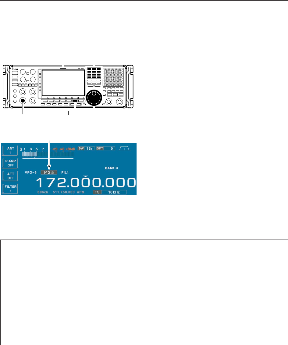
4-18
4RECEIVE MODES
■Operating P25 (Requires optional UT-122)
qEdit the desired frequency using the keypad.
wPush [DIGITAL] to select P25.
• “P25” indicator appears.
eRotate the main dial to tune the desired frequency.
• [RX] indicator lights green and the S-meter indicates re-
ceived signal strength when signal is received.
rRotate [AF] to set audio to a comfortable listening
level.
DConvenient functions for P25
Appears
Keypad[RX] indicator
[AF] [DIGITAL] Main dial
• Preamp (p. 5-9)
➥Push [P.AMP] several times to set the preamp
OFF, preamp 1 ON or preamp 2 ON. Only
ON/OFF is available above 30 MHz.
• “P.AMP1” or “P.AMP2” appears when the preamp 1 or
preamp 2 is ON below 30 MHz. “P.AMP ON” appears
above 30 MHz.
• Attenuator (p. 5-9)
➥Push [ATT] several times to set the attenuator in
6 dB steps for HF bands, or 10 dB step for
30–1150 MHz. Only 20 dB is available for
1150–3335 MHz.
• “ATT” and attenuation level appear when the attenu-
ator is ON.
• Twin PBT (passband tuning) (p. 5-11)
➥Rotate [TWIN PBT] controls (inner/outer).
• Push [PBT CLEAR] to clear the settings.