ICOM orporated 285200 VHF-FM Marine Transceiver User Manual IC M422 FCC
ICOM Incorporated VHF-FM Marine Transceiver IC M422 FCC
UserManual.wiki
>
ICOM orporated
>
285200 User Manual
Manual
Navigation menu
Upload a User Manual
Namespaces
Wiki Guide
HTML
PDF
Info
Views
User Manual
Discussion / Help
Navigation
![iiIN CASE OF EMERGENCYIf your vessel requires assistance, contact other vessels andthe Coast Guard by sending a distress call on Channel 16.Or, transmit your distress call using digital selective calling onChannel 70.NOTEA WARNING STICKER is supplied with the transceiver.To comply with FCC regulations, this sticker must be affixed insuch a location as to be readily seen from the operating con-trols of the radio. Make sure the chosen location is clean anddry before applying the sticker.USING DIGITAL SELECTIVE CALLING (Ch 70)DISTRESS CALL PROCEDURE1. While lifting up the key cover, push and hold[DISTRESS] for 5 sec. until you hear 5 short beepschange to one long beep.2. Wait for an acknowledgment from a coast station.• Channel 16 is automatically selected.3. Push and hold [PTT], then transmit the appropriateinformation as listed above.USING CHANNEL 16DISTRESS CALL PROCEDURE1. “MAYDAY MAYDAY MAYDAY.”2. “THIS IS ...............” (name of vessel)3. Your call sign or other indication of the vessel (AND 9-digit DSC ID if you have one).4. “LOCATED AT ...............” (your position)5. The nature of the distress and assistance required.6. Any other information which might facilitate the rescue.New2001!IC-M422_FCC.qxd 05.1.14 11:30 AM Page ii (1,1)](https://usermanual.wiki/ICOM-orporated/285200/User-Guide-523416-Page-3.png)
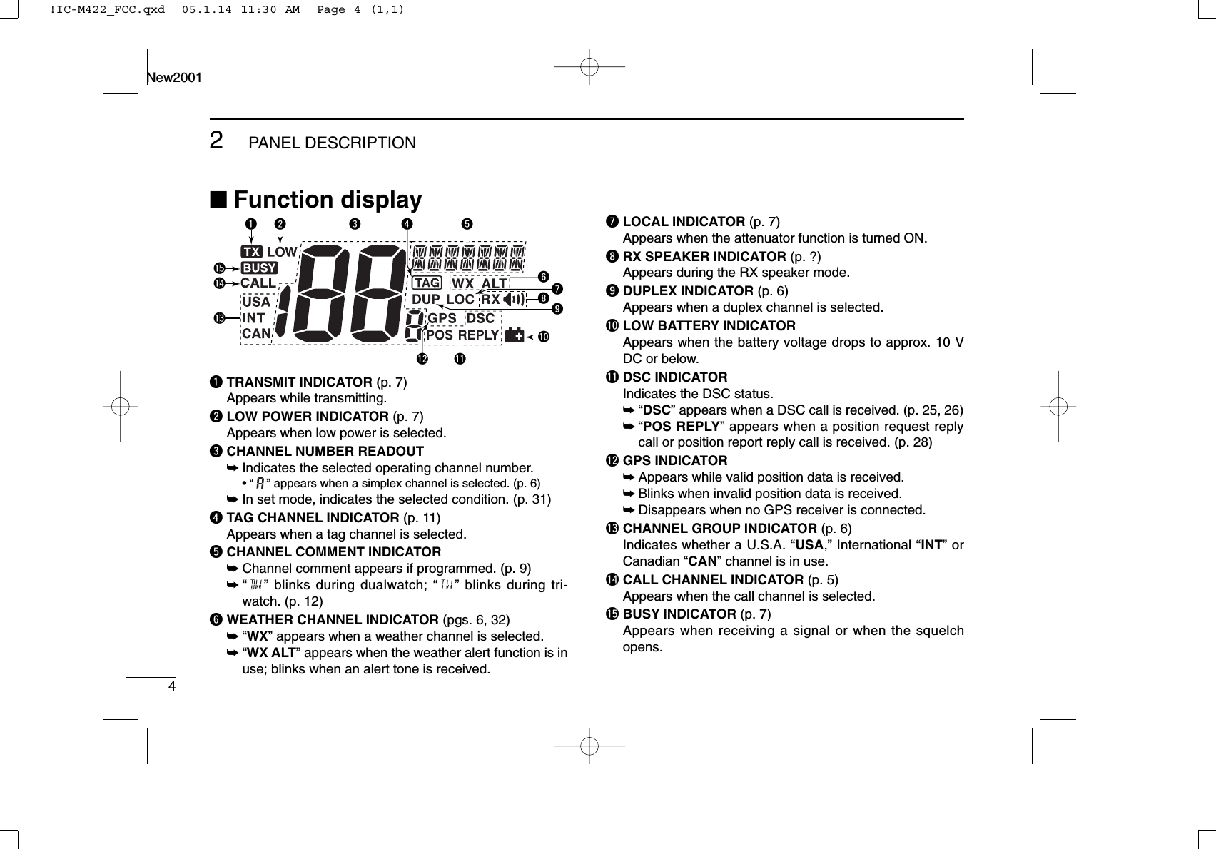
![2PANEL DESCRIPTIONNew20012■Front panelqCHANNEL 16/CALL CHANNEL KEY [16•9]➥Push to select Channel 16. (p. 5)➥Push for 1 sec. to select call channel. (p. 5)•“CALL” appears when call channel is selected.➥Push for 3 sec. to enter call channel programming con-dition when call channel is selected. (p. 8)➥While pushing [CH/WX•DUAL], push to enter the chan-nel comments programming condition. (p. 9)➥While turning power ON, push to enter set mode. (p. 31)wCHANNEL/WEATHER CHANNEL KEY [CH/WX•DUAL]➥Toggles between regular channels and weather chan-nel when pushed momentarily. (p. 6)➥Push for 1 sec. to start dualwatch or tri-watch. (p. 12)➥Push to stop dualwatch or tri-watch when either is acti-vated.eDSC/POSITION KEY [DSC•POS]➥Push to select the DSC menu. (p. 13)➥Push for 1 sec. to show the current position from a GPSreceiver. (p. 15)rPOWER/VOLUME CONTROL [VOL]➥Push for 1 sec. to turn power ON and OFF.➥Rotate to adjust the audio level. (p. 7)tSQUELCH CONTROL [SQL]Rotate to set the squelch threshold level. (p. 7)yDISTRESS KEY [DISTRESS]Push for 5 sec. to transmit a distress call. (p. 16)uATTENUATOR/INTERCOM KEY [Lo/DX•IC]➥Push to toggle the attenuator function ON or OFF. (p. 7)•“LOC” appears when the Attenuator function is turned ON.➥Push for 1 sec. to activate an optional intercom function.(p. ?)➥Push for 1 sec. to call the optional HM-157 COMMAND-MIC II™ while in Intercom mode. (p. ?)qwerSpeakerFunctiondisplay (p.4)!0 oiuy t!IC-M422_FCC.qxd 05.1.14 11:30 AM Page 2 (1,1)](https://usermanual.wiki/ICOM-orporated/285200/User-Guide-523416-Page-8.png)
![32PANEL DESCRIPTIONNew2001iPUBLIC ADDRESS/RX SPEAKER KEY [PA•RX ]➥Push to turn the public address mode ON or OFF. (p. ?)➥Push for 1 sec. to turn the RX speaker mode ON orOFF. (p. ?)oSCAN KEY [SCAN•TAG](p. 10)➥Push to start and stop normal or priority scan.➥Push for 1 sec. to set or clear the displayed channel asa tag (scanned) channel.➥While pushing [HI/LO] on the microphone, push for 3sec. to clear or set all tag channels in the selected chan-nel group.!0 CHANNEL UP/DOWN KEYS [YY]/[ZZ]•[U/I/C]➥Push to select the operating channels, set mode set-tings, etc. (pgs. 5, 6, 34)➥Push and hold [Y]to increment the operating channelcontinuously.➥Push and hold [Z]to decrement the operating channelcontinuously.➥While pushing [SCAN•TAG], push [Y]or [Z]to adjustthe brightness of the LCD and key backlight. (p. 9)➥Push both keys to select one of three channel groupsin sequence. (p. 6)•International, U.S.A. and Canadian channels are available.■MicrophoneqPTT SWITCH [PTT]Push and hold to transmit; release to receive. (p. 7)wCHANNEL UP/DOWN KEYS [YY]/[ZZ]Push either key to change the operating memory channel,Set mode settings, etc. (pgs. 5, 6, 34)eTRANSMIT POWER KEY [HI/LO]➥Toggles power high and lower when pushed. (p. 7)•Some channels are set to low power only.➥While pushing [HI/LO], turn power ON to toggle the mi-crophone lock function ON and OFF. (p. 9)SpeakerMicrophonewqe2!IC-M422_FCC.qxd 05.1.14 11:30 AM Page 3 (1,1)](https://usermanual.wiki/ICOM-orporated/285200/User-Guide-523416-Page-9.png)
![53BASIC OPERATION3■Channel selectionïïChannel 16Channel 16 is the distress and safety channel. It is used forestablishing initial contact with another station and for emer-gency communications. Channel 16 is monitored during bothdualwatch and tri-watch. While standing by, you must monitorChannel 16.➥Push [16•9]momentarily to select Channel 16.➥Push [CH/WX•DUAL]to return to the condition before select-ing Channel 16, or push [Y]or [Z]to select operating chan-nel.ïïChannel 9 (Call channel)Each regular channel group has a separate leisure-use callchannel. The call channel is monitored during tri-watch. Thecall channels can be programmed (p. 8) and are used to storeyour most often used channels in each channel group forquick recall.➥Push [16•9]for 1 sec. to select the call channel of the se-lected channel group.•“CALL” and call channel number appear.•Each channel group may have an independent call channel afterprogramming a call channel. (p. 8)➥Push [CH/WX•DUAL]to return to the condition before se-lecting call channel, or push [Y]or [Z]to select an oper-ating channel.Pushfor 1 sec.Push!IC-M422_FCC.qxd 05.1.14 11:30 AM Page 5 (1,1)](https://usermanual.wiki/ICOM-orporated/285200/User-Guide-523416-Page-11.png)
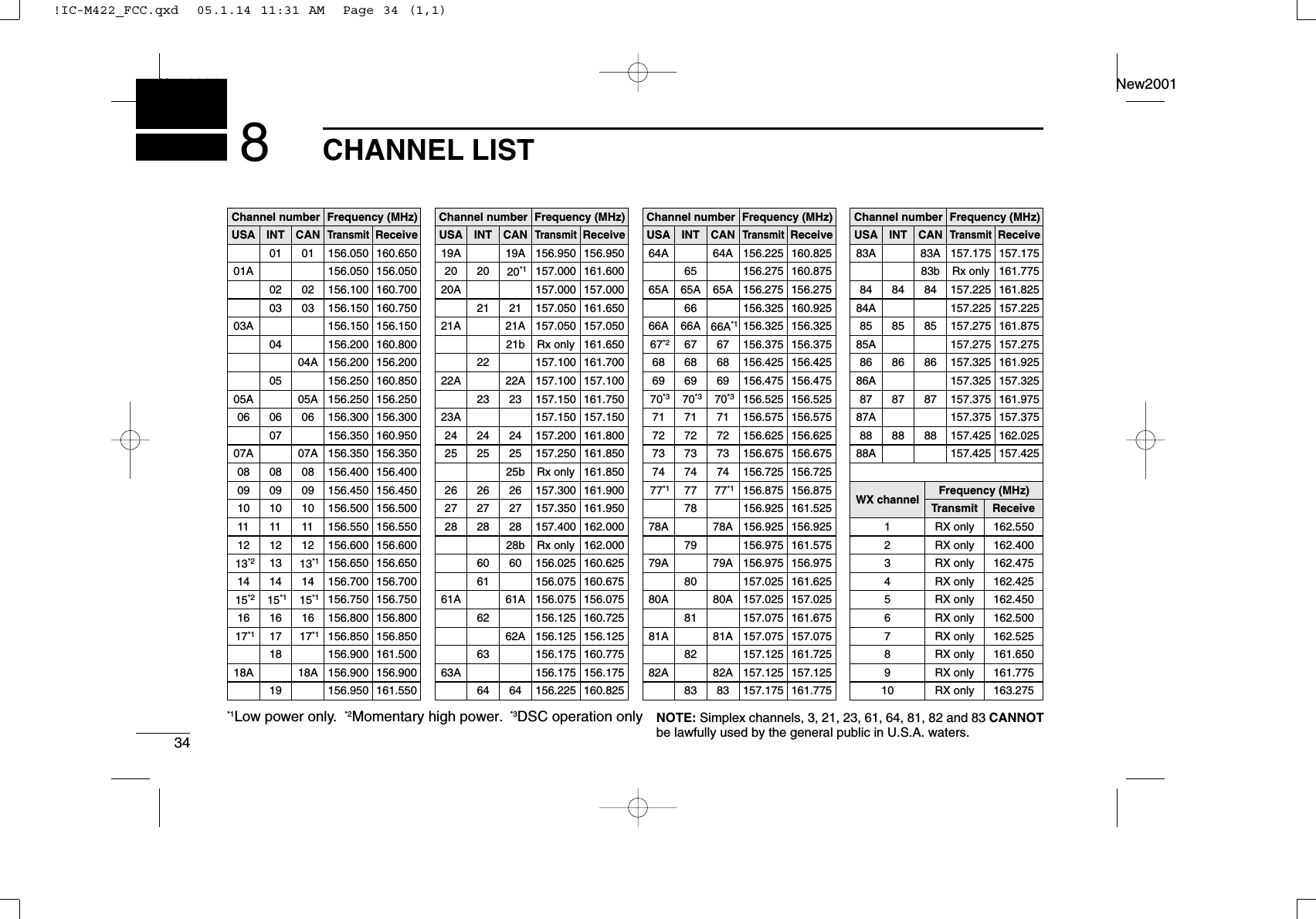
![63BASIC OPERATIONNew2001ïïU.S.A.,Canadian and international channelsThe IC-M422 are pre-programmed with 57 U.S.A., 61 Cana-dian and 57 international channels. These channel groupsmay be specified for the operating area.qPush [CH/WX•DUAL]to select a regular channel.•If a weather channel appears, push [CH/WX•DUAL]again.wPush both [Y]and [Z]on the transceiver to change thechannel group, if necessary.•U.S.A., International and Canadian channels can be selected insequence.ePush [Y]or [Z]to select a channel.•“DUP” appears for duplex channels.•“ ” appears when a simplex channel is selected.ïïWeather channelsThe IC-M422 has 10 weather channels. These are used formonitoring broadcasts from NOAA (National Oceanographicand Atmospheric Administration.)The transceiver can detect a weather alert tone on the se-lected weather channel while receiving the channel, duringstandby on a regular channel or while scanning. (p. 32)qPush [CH/WX•DUAL]once or twice to select a weatherchannel.•“WX” appears when a weather channel is selected.• “WX ALT” appears when the Weather alert function is in use.(p. 32)wPush [Y]or [Z]to select a channel.ScrollsAppearsScrollsAppearsWhen Weather alert is OFF.When Weather alert is ON.Push once or twicePush and!IC-M422_FCC.qxd 05.1.14 11:30 AM Page 6 (1,1)](https://usermanual.wiki/ICOM-orporated/285200/User-Guide-523416-Page-12.png)
![73BASIC OPERATIONNew20013■Receiving and transmittingCAUTION: Transmitting without an antenna may dam-age the transceiver.qPush [VOL] for 1 sec. to turn power ON.wSet the audio and squelch levels.➥Rotate [SQL] fully counterclockwise in advance.➥Rotate [VOL] to adjust the audio output level.➥Rotate [SQL] clockwise until the noise disappears.eTo change the channel group, push both [Y]and [Z]onthe transceiver. (p. 6)rPush [Y]or [Z]to select the desired channel. (p. 6)•When receiving a signal, “” appears and audio is emittedfrom the speaker.•Further adjustment of [VOL] may be necessary.tPush [LO/DX•IC]to turn the receive attenuator functionON or OFF, if necessary.•“ ” appears when the receive attenuator function is in use.yPush [HI/LO] to select the output power if necessary.•“LOW” appears when low power is selected.•Choose low power for short range communications, choose highpower for longer distance communications.•Some channels are for low power only.uPush and hold [PTT] to transmit, then speak into the mi-crophone (M).•“ ” appears.•Channel 70 cannot be used for transmission other than DSC.iRelease [PTT] to receive.Simplex channels, 3, 21, 23, 61, 64, 81, 82 and 83 CAN-NOT be lawfully used by the general public in U.S.A. wa-ters.IMPORTANT: To maximize the readability of your trans-mitted signal, pause a few sec. after pushing [PTT], holdthe microphone 2 to 4 inches (5 to 10 cm) from your mouthand speak into the microphone (M) at a normal voice level.iryMuqM: Microphonewrte!IC-M422_FCC.qxd 05.1.14 11:30 AM Page 7 (1,1)](https://usermanual.wiki/ICOM-orporated/285200/User-Guide-523416-Page-13.png)
![83BASIC OPERATIONNew2001■Call channel programmingCall channel is used to select Channel 9 (default), however,you can program the call channel with your most often-usedchannels in each channel group for quick recall.qPush both [Y]and [Z]onthe transceiver one or moretimes to select the desiredchannel group (U.S.A., In-ternational or Canada) to beprogrammed.wPush [16•9]for 1 sec. to se-lect the call channel of theselected channel group.•“CALL” and call channel num-ber appear.ePush [16•9]again for 3 sec.(until a long beep changesto 2 short beeps) to entercall channel programmingcondition.•Channel number starts blink-ing.rPush [Y]or [Z]to selectthe desired channel.tPush [16•9]to program thedisplayed channel as thecall channel.•Push [CH/WX•DUAL]to can-cel.•The channel number stopsblinking.!IC-M422_FCC.qxd 05.1.14 11:30 AM Page 8 (1,1)](https://usermanual.wiki/ICOM-orporated/285200/User-Guide-523416-Page-14.png)
![93BASIC OPERATIONNew20013■Channel commentsMemory channels can be labeled with alphanumeric com-ments of up to 10 characters each for easy channel recogni-tion.More than 7 characters comment scrolls automatically at thechannel comment indicator after the channel selection.Capital letters, small letters (except f, j, k, p, s, v, x, z), 0 to 9,some symbols (– . /) and space can be used.qSelect the desired channel.•Cancel dualwatch, tri-watch or scan in advance.wWhile pushing [CH/WX•DUAL], push [16•9]to editthe channel comment.•A cursor and the first char-acter start blinking alter-nately.eSelect the desired charac-ter by pushing [Y]or [Z].• Push [CH/WX•DUAL]or [16•9]to move the cursor forward orbackward, respectively.rRepeat step eto input all characters.tPush [DSC•POS]to input and set the comment.•Push [LO/DX•IC]to cancel.•A cursor and the character stop blinking.yRepeat steps qto tto program other channel com-ments, if desired.■Microphone lock functionThe microphone lock function electrically locks [Y]/[Z]and[HI/LO] keys on the supplied microphone. This prevents ac-cidental channel changes and function access.➥While pushing [HI/LO] on the microphone, turn power ONto toggle the lock function ON and OFF.■Display backlightingThe function display and keys can be backlit for better visibil-ity under low light conditions.➥While pushing [SCAN•TAG], push [Y]or [Z]to adjust thebrightness of the LCD and key backlight.•The backlight is selectable in 7 levels and OFF.[HI/LO][Y]/[Z]!IC-M422_FCC.qxd 05.1.14 11:30 AM Page 9 (1,1)](https://usermanual.wiki/ICOM-orporated/285200/User-Guide-523416-Page-15.png)
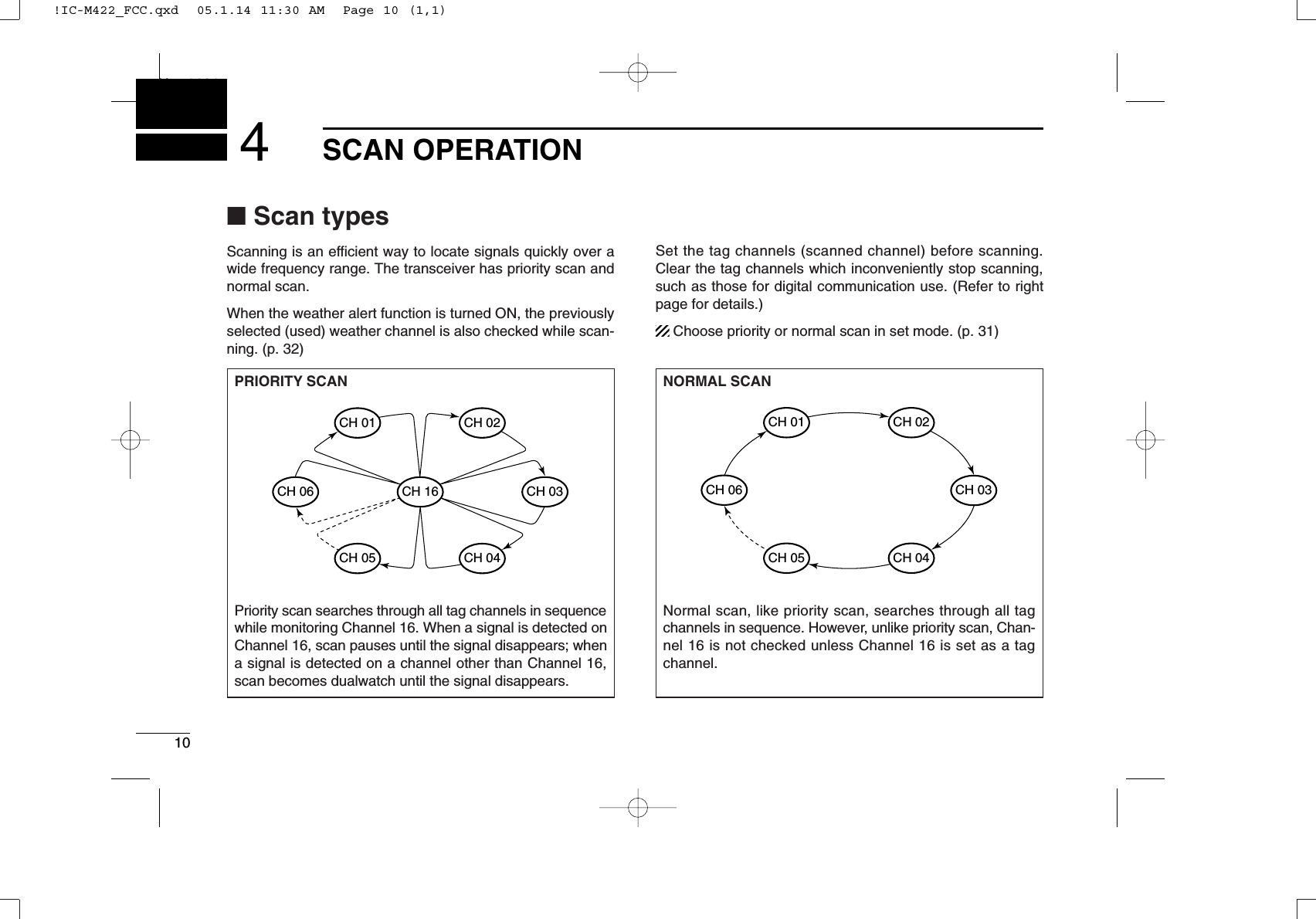
![114SCAN OPERATIONNew20014■Setting tag channelsFor more efficient scanning, add the desired channels as tagchannels or clear the tag for unwanted channels. Channels are not tagged will be skipped during scanning. Tagchannels can be assigned to each channel group (USA, INT,CAN) independently.qPush both [Y]and [Z]to select the desired channel group(USA, INT or CAN.)wSelect the desired channel to be set as a tag channel.ePush [SCAN•TAG]for 1 sec. to set the displayed channelas a tag channel.•“ ” appears in the display.rTo cancel the tag channel setting, repeat step e.•“ ” disappears.✔Clearing (or setting) all tagged channelsWhile pushing [HI/LO] on the microphone, push [SCAN•TAG]for 3 sec. (until a long beep changes to 2 short beeps) to clearall tag channels in the channel group.• Repeat above procedure to set all tag channels.■Starting a scanSet scan type (priority or normal scan) and scan resume timerin advance, using set mode. (p. 31)qPush both [Y]and [Z]to select the desired channel group(USA, INT, CAN) if desired.wSet tag channels as described at left.eMake sure the squelch is closed to start a scan.rPush [SCAN•TAG]to start priority or normal scan.•“ ” appears at the channel comment indicator during pri-ority scan.•“ ” appears at the channel comment indicator during normalscan.•When a signal is detected, scan pauses until the signal disap-pears or resumes after pausing 5 sec. according to set modesetting. (Channel 16 is still monitored during priority scan.)•Push [Y]or [Z]to check the scanning tag channels, to changethe scanning direction or resume the scan manually.•A beep tone sounds and “” blinks at the channel comment in-dicator when a signal is received on Channel 16 during priorityscan.tTo stop the scan, repeat step r.[Example]: Starting a normal scan.PushScan starts.When a signal isreceived.!IC-M422_FCC.qxd 05.1.14 11:30 AM Page 11 (1,1)](https://usermanual.wiki/ICOM-orporated/285200/User-Guide-523416-Page-17.png)
![12DUALWATCH/TRI-WATCHNew20015■DescriptionDualwatch monitors Channel 16 while you are receiving another channel; tri-watch monitors Channel 16 and the callchannel while receiving another channel. Dualwatch/tri-watchis convenient for monitor Channel 16 when you are operatingon another channel.■OperationqSelect dualwatch or tri-watch in set mode. (p. 32)wPush [Y]or [Z]to select the desired operating channel.ePush [CH/WX•DUAL]for 1 sec. to start dualwatch or tri-watch.•“ ” blinks during dualwatch; “” blinks during tri-watch.•A beep tone sounds when a signal is received on Channel 16.rTo cancel dualwatch/tri-watch, push [CH/WX•DUAL]again.DUALWATCH/TRI-WATCH SIMULATION•If a signal is received on Channel 16, dualwatch/tri-watchpauses on Channel 16 until the signal disappears.•If a signal is received on the call channel during tri-watch,tri-watch becomes dualwatch until the signal disappears.•To transmit on the selected channel during dualwatch/tri-watch, push and hold [PTT].Dualwatch Tri-watchCall channel[Example]: Operating tri-watch on INT Channel 25Tri-watch starts.Signal is received on call channel.Signal is received on Channel 16 takes priority.Tri-watch resumes after the signal disappears.!IC-M422_FCC.qxd 05.1.14 11:30 AM Page 12 (1,1)](https://usermanual.wiki/ICOM-orporated/285200/User-Guide-523416-Page-18.png)
![136DSC OPERATION56■MMSI code programmingThe 9-digit MMSI (Maritime Mobile Service Identity: DSC selfID) code can be programmed at power ON.This function is not available when the MMSI code hasbeen programmed by the dealer. This code programmingcan be performed only twice.qTurn power OFF.wWhile pushing [DSC•POS], turn power ON to enter MMSIcode programming condition.eAfter the display appears, release [DSC•POS].•A cursor starts blinking.rEdit the specified MMSI code by pushing [Y]or [Z].• Push [CH/WX•DUAL]or [16•9]to move the cursor forward orbackward, respectively.tInput 9-digit code, then push [DSC•POS]to set the code.•Returns to the normal operation.■MMSI code checkThe 9-digit MMSI (DSC self ID) code can be checked.qPush [DSC•POS]to enter the DSC menu.wPush [Y]or [Z]to select “” and push [DSC•POS].eCheck the 9-digit MMSI (DSC self ID) code.• The MMSI code is displayed and scrolls at the channel commentindicator.rPush [DSC•POS]to exit the DSC menu.MMSI (DSC self ID) code scrolls!IC-M422_FCC.qxd 05.1.14 11:30 AM Page 13 (1,1)](https://usermanual.wiki/ICOM-orporated/285200/User-Guide-523416-Page-19.png)
![146DSC OPERATIONNew2001■DSC individual IDA total of 100 DSC address IDs (9-digit) can be programmedand named with up to 7 characters.DProgramming Address ID/Group IDqPush [DSC•POS]to enter the DSC menu.wPush [Y]or [Z]to select “,” push [DSC•POS].ePush [Y]or [Z]to select “,” push [DSC•POS].rPush [Y]or [Z]to set the 9-digit individual/group ID.•Push [CH/WX•DUAL]or [16•9]to move the cursor forward orbackward, respectively.•Push [LO/DX•IC]to cancel and exit the condition.1st digit ‘0’is fixed for a group ID. When you input 1st digit ‘0’and other 8 digits, the ID is automatically registered as a groupID.tAfter input the 9-digit code, push [DSC•POS]to set up to a5-character ID name using [Y]or [Z].•Push [CH/WX•DUAL]or [16•9]to move the cursor forward orbackward, respectively.•Push [LO/DX•IC]to cancel and exit the condition.yPush [DSC•POS]to program and exit the DSC menu.!IC-M422_FCC.qxd 05.1.14 11:30 AM Page 14 (1,1)](https://usermanual.wiki/ICOM-orporated/285200/User-Guide-523416-Page-20.png)
![156DSC OPERATIONNew20016DDeleting Address ID/Group IDqPush [DSC•POS]to enter the DSC menu.wPush [Y]or [Z]to select “,” and push [DSC•POS].ePush [Y]or [Z]to select “”, push [DSC•POS].•When no address ID is programmed, “” is displayed.rPush [Y]or [Z]to select the desired ID name for deletingand push [DSC•POS].• “” appears.tPush [DSC•POS]to delete the address ID and exit theDSC menu.■Position indicationWhen a GPS receiver (NMEA0183 ver. 2.0 or 3.01) is con-nected, the transceiver displays the current position data inseconds of accuracy.A NMEA0183 ver. 2.0 or 3.01 (sentence formatters RMC,GGA, GNS, GLL) compatible GPS receiver is required. Askyour dealer about suitable GPS receivers.➥Push [DSC•POS]for 1 sec. to display the current position.•‘Latitude’and ‘Longitude’scroll in sequence at the channel com-ment indicator.• “” scrolls when no GPS is connected.• When the connecting GPS receiver is compatible withseveral sentence formatters, the order of input prece-dence is ‘RMC,’‘GGA,’‘GNS’and ‘GLL.’• “GPS” blinks when the GPS data is invalid.Scrolls!IC-M422_FCC.qxd 05.1.14 11:30 AM Page 15 (1,1)](https://usermanual.wiki/ICOM-orporated/285200/User-Guide-523416-Page-21.png)
![166DSC OPERATIONNew2001■Distress callA distress call should be transmitted, if in the opinion of theMaster, the ship or a person is in distress and requires imme-diate assistance.NEVER USE THE DISTRESS CALL WHEN YOURSHIP OR A PERSON IS NOT IN AN EMERGENCY.A DISTRESS CALL CAN BE USED ONLY WHENIMMEDIATE HELP IS NEEDED.qConfirm no distress call is being received.wWhile lifting up the key cover, push [DISTRESS] for 5 sec.to transmit the distress call.•Emergency channel (Ch 70) is automatically selected and thedistress call is transmitted.• While pushing [DISTRESS], the key backlighting is blinking.eAfter transmitting the distress call, the transceiver waits foran acknowledgment call on Ch70.•The distress call is automatically transmitted every 3.5 to 4.5minutes.•“ ” scrolls at the channel comment indicator.rAfter receiving the acknowledgment, reply using the mi-crophone.•Channel 16 is automatically selected.•“ ” scrolls at the channel comment indicator.➥A distress alert contains;• Kinds of distress: Undesignated distress•Position data : Latest GPS position data held for 23.5 hrs.or until the power is turned OFF.➥The distress call is repeated every 3.5–4.5 min., until re-ceiving an ‘acknowledgement.’➥Push [DISTRESS] to transmit a renewed Distress call, if desired.➥Push [16•9]to cancel the ‘Call repeat’mode.ScrollsScrolls!IC-M422_FCC.qxd 05.1.14 11:30 AM Page 16 (1,1)](https://usermanual.wiki/ICOM-orporated/285200/User-Guide-523416-Page-22.png)
![176DSC OPERATIONNew20016■Transmitting DSC callsTo ensure correct operation of the DSC function, pleasemake sure you set the squelch correctly. (P. 7)DTransmitting an individual callThe individual call function allows you to transmit a DSC sig-nal to a specific ship only.qPush [DSC•POS]to enter the DSC menu.wPush [Y]or [Z]to select “,” push [DSC•POS].wPush [Y]or [Z]to select the desired pre-programmed in-dividual address, push [DSC•POS].• The ID code must be set in advance. (p. 14)ePush [Y]or [Z] to select the desired intership channel,push [DSC•POS].• Intership channels are already preset into the transceiver in rec-ommending order.• After pushing [DSC•POS], Channel 70 is selected and “”appears at the channel comment indicator.rPush [DSC•POS]to transmit the individual call.•If Channel 70 is busy, the transceiver stands by until the channelbecomes clear.•Routine category only is available.TransmittingPushScrolls!IC-M422_FCC.qxd 05.1.14 11:30 AM Page 17 (1,1)](https://usermanual.wiki/ICOM-orporated/285200/User-Guide-523416-Page-23.png)
![186DSC OPERATIONNew2001tStands by on Channel 70 until an acknowledgement is re-ceived.•“ ” scrolls at the channel comment indicator.yWhen the acknowledgement ‘Able to comply’is received,the specified channel (in step e) is selected with beepsautomatically. Or, when the acknowledgement ‘Unable tocomply’is received, the display returns to the operatedchannel (before enter the DSC menu) with beeps.•“ ” or “” scrolls at the channelcomment indicator.uPush any key to stop the beep, then push and hold [PTT]to communicate your message to the responding ship.DTransmitting an individual acknowledgementWhen receiving an individual call, you can transmit an ac-knowledgement (‘Able to comply’or ‘Unable to comply’) byusing the on screen prompts (see page 26 for details). Alter-natively, you can send an acknowledgement through themenu system as follows.qPush [DSC•POS]to enter the DSC menu.wPush [Y]or [Z] to select “,” push [DSC•POS].• “” item appears after an individual call is received.• “” item disappears if another call is received after theindividual call.• The individual acknowledgement can be transmitted to the lastreceived individual call only.Scrolls‘Able to comply’ is received.Scrolls‘Unable to comply’ is received.ScrollsScrolls!IC-M422_FCC.qxd 05.1.14 11:30 AM Page 18 (1,1)](https://usermanual.wiki/ICOM-orporated/285200/User-Guide-523416-Page-24.png)
![196DSC OPERATIONNew20016ePush [Y]or [Z]to select the acknowledgement “” or“.”• When “” is selected, the reason “No Reason Given” willbe transmitted.rPush [DSC•POS]to enter selected individual call acknowl-edgement.• “” appears at the channel comment indicator.tPush [DSC•POS]to transmit the acknowledgement call tothe selected station.yAfter the individual acknowledgement call has been trans-mitted, the specified channel (specified by the calling sta-tion) is selected automatically when “” is selected, orreturns to the previous condition (before entering the DSCmenu) when “” is selected in step e.ScrollsTransmitting‘ABLE’ is selected.!IC-M422_FCC.qxd 05.1.14 11:30 AM Page 19 (1,1)](https://usermanual.wiki/ICOM-orporated/285200/User-Guide-523416-Page-25.png)
![DTransmitting a group callThe group call function allows you to transmit a DSC signal toa specific group only.qPush [DSC•POS]to enter the DSC menu.wPush [Y]or [Z] to select “,” push [DSC•POS].ePush [Y]or [Z] to select the desired pre-programmedgroup address, push [DSC•POS].• The ID code must be set in advance. (p. 14)rPush [Y]or [Z] to select the desired intership channel,and push [DSC•POS].• Intership channels are already preset into the transceiver in rec-ommending order.• After pushing [DSC•POS], Channel 70 is selected and “”appears at the channel comment indicator.tPush [DSC•POS]to transmit the group call.•If Channel 70 is busy, the transceiver stands by until the channelbecomes clear.•Routine category only is available.yAfter the group call has been transmitted, the specifiedchannel (in step r) is selected automatically.uPush and hold [PTT] to communicate your message to theresponding ship.ScrollsTransmittingPush206DSC OPERATIONNew2001!IC-M422_FCC.qxd 05.1.14 11:30 AM Page 20 (1,1)](https://usermanual.wiki/ICOM-orporated/285200/User-Guide-523416-Page-26.png)
![216DSC OPERATIONNew20016DTransmitting an all ships callLarge ships use Channel 70 as their ‘listening channel.’When you want to announce a message to these ships, usethe ‘all ships call’function.qPush [DSC•POS]to enter the DSC menu.wPush [Y]or [Z]to select “.”ePush [DSC•POS]to enter the standby condition for AllShips call.• Channel 70 is selected and “” appears at the channelcomment indicator.rPush [DSC•POS]to transmit the all ships call.• Routine category only is available.tAfter the all ships call has been transmitted, Channel 16 isselected automatically.TransmittingScrolls!IC-M422_FCC.qxd 05.1.14 11:30 AM Page 21 (1,1)](https://usermanual.wiki/ICOM-orporated/285200/User-Guide-523416-Page-27.png)
![226DSC OPERATIONNew2001DTransmitting a position request callTransmit a position request call when you want to know aspecified ship’s current position, etc.qPush [DSC•POS]to enter the DSC menu.wPush [Y]or [Z] to select “,” push [DSC•POS].ePush [Y]or [Z] to select the desired pre-programmed in-dividual address.• The ID code must be set in advance. (p. 14)rPush [DSC•POS]to enter the standby condition for posi-tion request call.• Channel 70 is selected and “” appears at the channelcomment indicator.tPush [DSC•POS]to transmit the position request call.yAfter the position request call has been transmitted, the fol-lowing indication is displayed.•“ ” scrolls at the channel comment indicator.uPush any key to exit the condition and return to the previ-ous indication before entering the DSC menu.ScrollsTransmittingScrolls!IC-M422_FCC.qxd 05.1.14 11:30 AM Page 22 (1,1)](https://usermanual.wiki/ICOM-orporated/285200/User-Guide-523416-Page-28.png)
![236DSC OPERATIONNew20016DTransmitting a position report callTransmit a position report call when you want to announceyour own position to a specific ship and to get an answer, etc.qPush [DSC•POS]to enter the DSC menu.wPush [Y]or [Z]to select “,” push [DSC•POS].ePush [Y]or [Z] to select the desired pre-programmed in-dividual address.• The ID code must be set in advance. (p. 14)rPush [DSC•POS]to enter the standby condition for posi-tion report call.• Channel 70 is selected and “” appears at the channelcomment indicator.tPush [DSC•POS]to transmit the position report call.yAfter the position report call has been transmitted, the fol-lowing indication is displayed.•“ ” scrolls at the channel comment indicator.uPush any key to exit the condition and return to the previ-ous indication before entering the DSC menu.ScrollsTransmittingScrolls!IC-M422_FCC.qxd 05.1.14 11:30 AM Page 23 (1,1)](https://usermanual.wiki/ICOM-orporated/285200/User-Guide-523416-Page-29.png)
![246DSC OPERATIONNew2001DTransmitting a polling request callTransmit a polling request call when you want to know a spe-cific ship is in the communication area, etc. qPush [DSC•POS]to enter the DSC menu.wPush [Y]or [Z]to select “,” push[DSC•POS].ePush [Y]or [Z] to select the desired pre-programmed in-dividual address.• The ID code must be set in advance. (p. 14)rPush [DSC•POS]to enter the standby condition for pollingrequest call.• Channel 70 is selected and “” appears at the channelcomment indicator.tPush [DSC•POS]to transmit the polling request call.yAfter the polling request call has been transmitted, the fol-lowing indication is displayed.•“ ” scrolls at the channel comment indicator.uPush any key to exit the condition and return to the previ-ous indication before entering the DSC menu.ScrollsTransmittingScrolls!IC-M422_FCC.qxd 05.1.14 11:30 AM Page 24 (1,1)](https://usermanual.wiki/ICOM-orporated/285200/User-Guide-523416-Page-30.png)
![256DSC OPERATIONNew20016DTransmitting a position request reply callTransmit a position request reply call when a position requestcall is received.qWhen a position request call is received, “DSC” appearsand “” scrolls at the channel comment in-dicator.wPush [DSC•POS]to reply to the position request call; pushother key to ignore the position request call.DTransmitting a position report reply callTransmit a position report reply call when a position report callis received.qWhen a position report call is received, “DSC” appears and“” scrolls at the channel comment indicator.wPush [DSC•POS]to reply to the position report call; pushother key to ignore the position report call.DTransmitting a polling request reply callTransmit a polling request reply call when a polling requestcall is received.qWhen a polling request call is received, “DSC” appearsand “” scrolls at the channel com-ment indicator.wPush [DSC•POS]to reply to the polling request call; pushother key to ignore the polling request call.ScrollsScrollsScrolls!IC-M422_FCC.qxd 05.1.14 11:30 AM Page 25 (1,1)](https://usermanual.wiki/ICOM-orporated/285200/User-Guide-523416-Page-31.png)
![266DSC OPERATIONNew2001■Receiving DSC callsDReceiving a distress callWhile monitoring Channel 70 and a distress call is received:➥The emergency alarm sounds for 2 minutes.•Push any key to stop the alarm.➥“DSC” appears and “” scrolls at the channelcomment indicator, then Channel 16 is selected automati-cally.➥Continue monitoring Channel 16 as a coast station may re-quire assistance.DReceiving a distress acknowledgementWhile monitoring Channel 70 and a distress acknowledge-ment to other ship is received:➥The emergency alarm sounds for 2 minutes.•Push any key to stop the alarm.➥“DSC” appears and “” scrolls at thechannel comment indicator, then Channel 16 is selectedautomatically.DReceiving a distress relay callWhile monitoring Channel 70 and a distress relay acknowl-edgement is received:➥The emergency alarm sounds for 2 minutes.•Push any key to stop the alarm.➥“DSC” appears and “” scrolls at the channel com-ment indicator, then Channel 16 is selected automatically.DReceiving an individual callWhile monitoring Channel 70 and an individual call is received:➥The emergency alarm or beeps sound depending on thereceived category.➥“DSC” appears and “” scrolls at the chan-nel comment indicator.➥Push any key to stop the beep, then push [DSC•POS]toreply the call and select the channel specified by the callingstation for voice communication (depending on your reply-ing condition. See p, 18 for individual acknowledgement callprocedure for details.); push any other key to ignore the call.ScrollsScrollsScrollsScrolls!IC-M422_FCC.qxd 05.1.14 11:30 AM Page 26 (1,1)](https://usermanual.wiki/ICOM-orporated/285200/User-Guide-523416-Page-32.png)
![276DSC OPERATIONNew20016DReceiving a group callWhile monitoring Channel 70 and a group call is received:➥The emergency alarm or beeps sound depending on thereceived category.➥“DSC” appears and “” scrolls at the channelcomment indicator.➥Push any key to stop the beep, then push [DSC•POS]toselect the channel specified by the calling station for voicecommunication; push any other key to ignore the call.DReceiving an all ships callWhile monitoring Channel 70 and an all ships call is received:➥The emergency alarm sounds when the category is ‘Dis-tress’or ‘Urgency’; 2 beeps sound for other categories.➥“DSC” appears and “” scrolls at the channelcomment indicator.➥Push any key to stop the beep, then push [DSC•POS]tomonitor Channel 16 for an announcement from the callingvessel, push any other key to ignore the call.DReceiving a geographical area callWhile monitoring Channel 70 and a geographical area call(for the area you are in) is received:➥The emergency alarm or beeps sound depending on thereceived category.➥“DSC” appears and “” scrolls at thechannel comment indicator.➥Push any key to stop the beep, then push [DSC•POS]toselect the channel specified by the calling station for voicecommunication; push any other key to ignore the call.➥Monitor the selected channel for an announcement fromthe calling station.When no GPS receiver is connected or if there is a prob-lem with the connected receiver, all geographical area callsare received, regardless of your position.ScrollsScrollsScrolls!IC-M422_FCC.qxd 05.1.14 11:30 AM Page 27 (1,1)](https://usermanual.wiki/ICOM-orporated/285200/User-Guide-523416-Page-33.png)
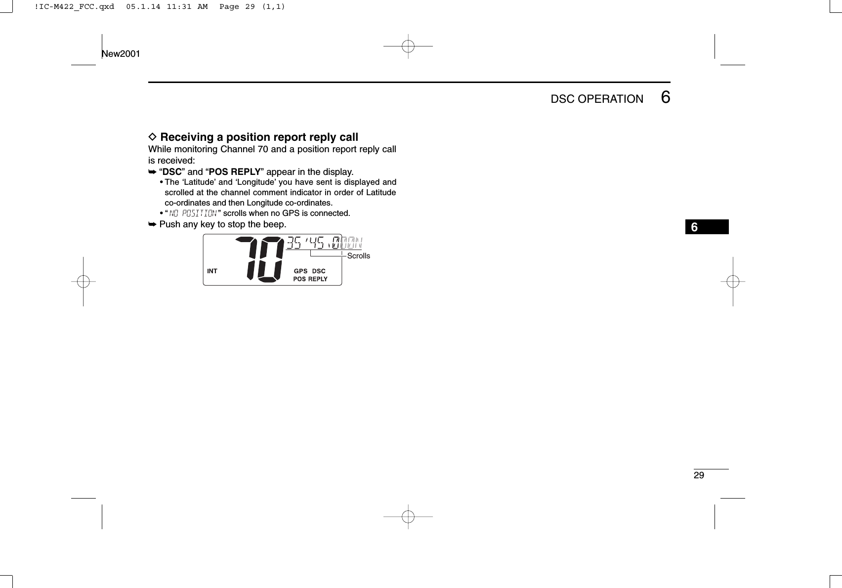
![286DSC OPERATIONNew2001DReceiving a position request callWhile monitoring Channel 70 and a position request call is re-ceived:➥“DSC” appears and “” scrolls at the chan-nel comment indicator.➥Push any key to stop the beep, then push [DSC•POS]toreply to the call; push any other key to ignore the call.DReceiving a position report callWhile monitoring Channel 70 and a position report call is re-ceived:➥“DSC” appears and “” scrolls at the chan-nel comment indicator.➥Push any key to stop the beep, then push [DSC•POS]toreply to the call; push any other key to ignore the call.DReceiving a polling request callWhile monitoring Channel 70 and a polling request call is re-ceived:➥“DSC” appears and “” scrolls at thechannel comment indicator.➥Push any key to stop the beep, then push [DSC•POS]toreply to the call; push any other key to ignore the call.DReceiving a position request reply callWhile monitoring Channel 70 and a position request reply callis received:➥“DSC” and “POS REPLY” appear in the display.•The ‘Latitude’and ‘Longitude’from the called station is displayedand scrolled at the channel comment indicator in order of Lati-tude co-ordinates and then Longitude co-ordinates.• “” scrolls when no GPS is connected.➥Push any key to stop the beep.ScrollsScrollsScrollsScrolls!IC-M422_FCC.qxd 05.1.14 11:31 AM Page 28 (1,1)](https://usermanual.wiki/ICOM-orporated/285200/User-Guide-523416-Page-34.png)
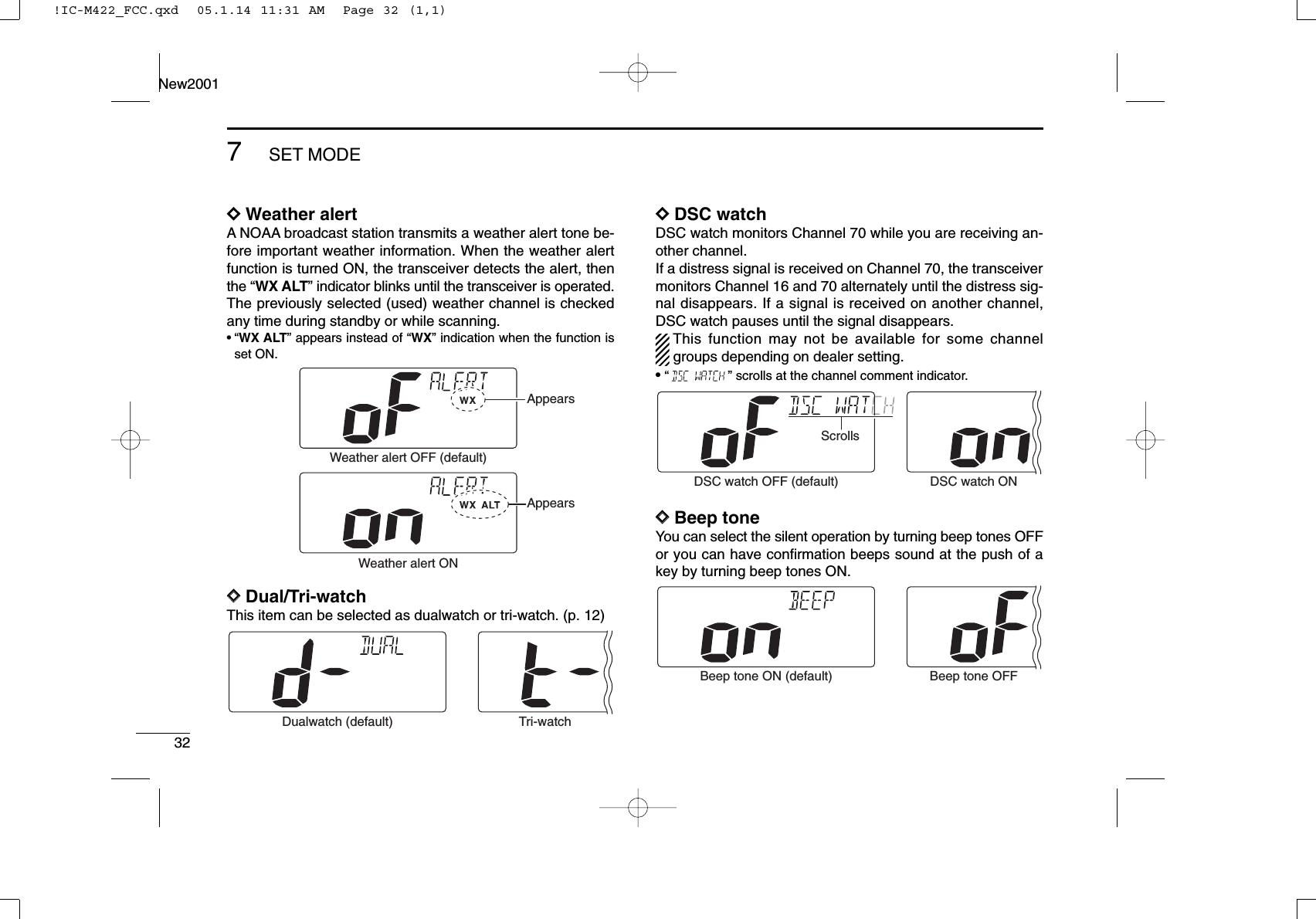
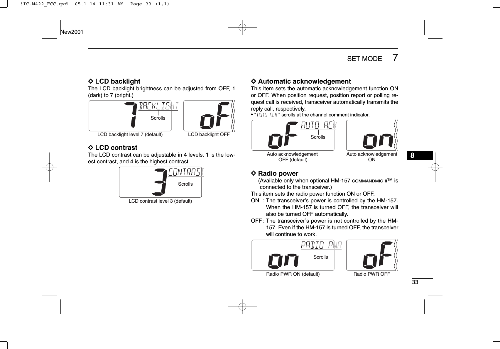
![317SET MODE67■Set mode programmingSet mode is used to change the conditions of the transceiver’sfunctions: Scan type (Normal or Priority,) Scan resume timer,Weather alert, Dual/Tri-watch, DSC watch, Beep tone (trans-ceiver,) LCD backlight, LCD contrast, Auto ACK and Radio PWR.Available functions may differ depending on dealer setting.qTurn power OFF.wWhile pushing [16•9], turn power ON to enter set mode.• “” appears at the channel comment indicator.eAfter the display appears, release [16•9].rPush [16•9]to select the desired item, if necessary.tPush [Y]or [Z]to select the desired condition of the item.yTurn power OFF, then ON again to exit set mode.■SET mode itemsDScan typeThe transceiver has 2 scan types: Normal scan and Priorityscan. Normal scan searches all tag channels in the selectedchannel group. Priority scan searches all tag channels in se-quence while monitoring Channel 16.DDScan resume timerThe scan resume timer can be selected as a pause (OFF) ortimer scan (ON). When OFF is selected, the scan pausesuntil the signal disappears. When ON is selected, the scanpauses 5 sec. and resumes even if a signal has been re-ceived on any other channel than Channel 16.Scan timer OFF (default) Scan timer ONNormal scan (default) Priority scanDSET MODE CONSTRUCTION: Push • Beep tone• Backlight• LCD contrast• Radio PWRStarting item • Scan type • Scan resume timer • Weather alert • Dual/Tri-watch • DSC watch• Auto acknowledgement!IC-M422_FCC.qxd 05.1.14 11:31 AM Page 31 (1,1)](https://usermanual.wiki/ICOM-orporated/285200/User-Guide-523416-Page-37.png)