ICOM orporated 287900 Communication Receiver User Manual
ICOM Incorporated Communication Receiver
User Manual

INSTRUCTION MANUAL
iR2500
COMMUNICATION RECEIVER
This device complies with Part 15 of the FCC rules. Operation is sub-
ject to the following two conditions: (1) This device may not cause
harmful interference, and (2) this device must accept any interference
received, including interference that may cause undesired operation.

i
FOREWORD
Thank you for purchasing this Icom product. The IC-R2500
VHF
/
UHF FM RECEIVER
is designed and built with Icom’s supe-
rior technology and craftsmanship. With proper care, this prod-
uct should provide you with years of trouble-free operation.
We want to take a couple of moments of your time to thank
you for making your IC-R2500 your radio of choice, and hope
you agree with Icom’s philosophy of “technology first.” Many
hours of research and development went into the design of
your IC-R2500.
DD
FEATURES
❍Wide frequency coverage with all mode re-
ceive
❍Both Remote controller operation and PC
control application are available
❍
ANF and NR functions are available (Only
when the optional DSP unit is installed.)
❍IF shift function
IMPORTANT
READ ALL INSTRUCTIONS carefully and completely
before using the receiver.
SAVE THIS INSTRUCTION MANUAL— This in-
struction manual contains important operating instructions for
the IC-R2500.
EXPLICIT DEFINITIONS
WORD DEFINITION
RWARNING!
CAUTION
NOTE
Personal injury, fire hazard or electric shock
may occur.
Equipment damage may occur.
Recommended for optimum use. No risk of
personal injury, fire or electric shock.
Icom, Icom Inc. and the logo are registered trademarks of Icom
Incorporated (Japan) in the United States, the United Kingdom, Ger-
many, France, Spain, Russia and/or other countries.

RWARNING! NEVER connect the receiver via the OPC-
254L to an AC outlet. This may pose a fire hazard or result in an elec-
tric shock.
RWARNING! NEVER operate the receiver while driving a
vehicle. Safe driving requires your full attention— anything less may
result in an accident.
NEVER connect the receiver to a power source of more than 14 V
DC. This will damage the receiver.
NEVER connect the receiver to a power source using reverse po-
larity. This will damage the receiver.
NEVER cut the DC power cable between the DC plug and fuse
holder. If an incorrect connection is made after cutting, the receiver
may be damaged.
NEVER expose the receiver to rain, snow or any liquids. The re-
ceiver may be damaged.
NEVER operate or touch the receiver with wet hands. This may
result in an electric shock or damage the receiver.
NEVER place the receiver where normal operation of the vehicle
may be hindered or where it could cause bodily injury.
NEVER let objects impede the operation of the cooling fan on the
rear panel.
AVOID using or placing the receiver in direct sunlight or in areas
with temperatures below –10°C (+14°F) or above +60°C (+140°F).
BE CAREFUL! The receiver will become hot when operating it
continuously for long periods.
AVOID setting the receiver in a place without adequate ventilation.
Heat dissipation may be affected, and the receiver may be damaged.
AVOID the use of chemical agents such as benzine or alcohol
when cleaning, as they can damage the receiver’s surfaces.
For U.S.A. only
CAUTION: Changes or modifications to this device, not ex-
pressly approved by Icom Inc., could void your authority to
operate this device under FCC regulations.
ii
PRECAUTION

iii
TABLE OF CONTENTS
FOREWORD ........................................................................................... i
IMPORTANT ............................................................................................ i
EXPLICIT DEFINITIONS ......................................................................... i
PRECAUTIONS ...................................................................................... ii
SUPPLIED ACCESSORIES .................................................................. iii
SPECIFICATIONS ................................................................................. iii
OPTIONS ............................................................................................... iii
TABLE OF CONTENTS ......................................................................... iii
1CONNECTION .............................................................................. 1–2
■Rear panel connection.................................................................... 1
■Antenna installation ........................................................................ 2
2PANEL DESCRIPTION ................................................................. 3–7
■Front panel—controller .................................................................. 3
■Function display—controller ........................................................... 5
■Rear panel—main unit ................................................................... 7
3SETTING A FREQUENCY .......................................................... 8–10
■Turning power ON/OFF ................................................................. 8
■Mode selection ............................................................................... 8
■Tuning step selection ..................................................................... 9
■Setting a frequency ........................................................................ 9
■Receive mode selection ............................................................... 10
4BASIC OPERATION ................................................................. 11–15
■Receiving ..................................................................................... 11
■Monitor function ............................................................................ 11
■Lock function ................................................................................ 11
■Attenuator function........................................................................ 12
■NB function .................................................................................. 12
■AGC function ................................................................................ 12
■AFC function ................................................................................ 13
SUPPLIED ACCESSORIES
Supplied accessories is described in the IC-PCR1500/2500’s
Instruction manual.
OPTIONS
UT-106*
DSP UNIT
Provides AF DSP functions such as noise reduction and auto notch.
CP-12L
CIGARETTE LIGHTER CABLES
For operation and charging via a 12 V cigarette lighter socket.
OPC-254L
DC POWER CABLES
For operation and charging via an external power supply.
SP-10
EXTERNAL SPEAKER
For all-round mobile operation. Cable length: 1.5 m; 4.9 ft
OPC-1156
SEPARATION CABLE
For extended separate installation. 3.5 m; 11.5 ft
*: UT-106 installation is described in the IC-PCR1500/2500’s Instruc-
tion manual.
SPECIFICATIONS
Specifications is described in the IC-PCR1500/2500’s In-
struction manual.

iv
1
2
3
4
5
6
7
8
9
10
11
12
13
14
■VSC function ................................................................................ 13
■IF filter selection ........................................................................... 14
■IF shift function ............................................................................. 14
■Duplex operation .......................................................................... 15
5MEMORY OPERATION ............................................................ 16–24
■General description ...................................................................... 16
■Memory channel selection ........................................................... 16
■Programming a memory channel ................................................. 17
■Programming channel names ..................................................... 18
■Copying memory contents ........................................................... 19
■Memory clearing .......................................................................... 21
■Memory bank setting .................................................................... 22
■Memory bank selection ................................................................ 23
■Transferring bank contents .......................................................... 23
6SCAN OPERATION .................................................................. 25–29
■Scan types ................................................................................... 25
■Scan start/stop ............................................................................. 26
■Scan edges programming ............................................................ 27
■Skip scan ..................................................................................... 28
■Scan resume condition ................................................................ 29
7PRIORITY WATCH .......................................................................... 30
■Priority watch types ...................................................................... 30
■Priority watch operation ............................................................... 30
8POCKET BEEP AND TONE SQUELCH ................................... 31–34
■Pocket beep operation ................................................................. 31
■Tone/DTCS squelch operation ..................................................... 33
■Tone scan ..................................................................................... 34
9SET MODE ................................................................................ 35–41
■General ........................................................................................ 35
■Set mode items ............................................................................ 35
10 OTHER FUNCTIONS ................................................................ 42–46
■Weather channel operation .......................................................... 42
■DSP operation .............................................................................. 43
■DATA cloning ................................................................................ 44
■Partial reset................................................................................... 45
■All reset......................................................................................... 45
■Internal audio switch..................................................................... 46
11 TROUBLESHOOTING .................................................................... 47
12 DOC ................................................................................................. 48
1
CONNECTION
1
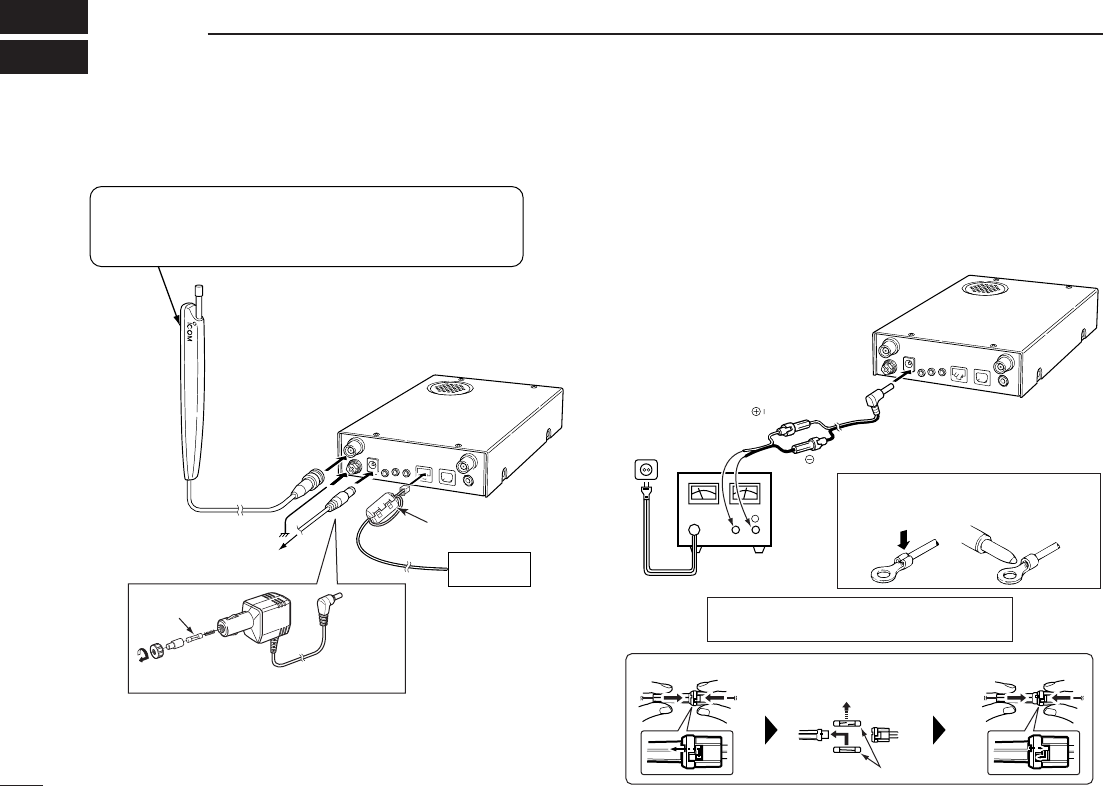
■Rear panel connection DDC power supply connection
Use a 12 V DC power supply with at least 4 A capacity.
Make sure the ground terminal of the DC power supply is
grounded.
•CONNECTING TO A DC POWER SUPPLY
OPC-254L
(optional)
black
white
R CAUTION! NEVER remove the fuse-
holders from the DC power cable.
Connects to a 12 V DC
battery. Pay attention
to polarities. NEVER
connect to a 24 V bat-
tery. This could dam-
age the receiver.
Solder
Crimp
NOTE: Use the terminals as shown
below for the cable connections.
D Fuse replacement
Receiver
Fuses (4 A)
DC power
supply 12 V
to an
AC outlet
−⊕
Ferrite core
Controller
CP-12L
(optional)
To a cigarette lighter socket
Fuse (4 A)
Or
Receiver
To ground
Supplied antenna
The double sided tape is set to the antenna holder.
Remove the protective paper when the antenna is
fixed to any place.
To AC adapter
2
1
CONNECTION
2
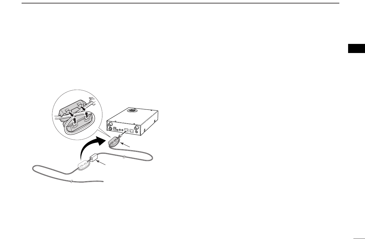
DDOPC-1156 connection
qConnect the controller plug to the OPC-1156 joint.
wDetach the ferrite core from the controller cable, then at-
tach it to the OPC-1156 as shown below.
• Make sure to roll the cable to the ferrite core.
eConnect the OPC-1156 plug to the [CONTROLLER] con-
nector of the receiver.
■Antennal installation
DAntenna location
To obtain maximum performance from the receiver, select a
high-quality antenna and mount it in a good location. A non-
radial antenna should be used when using a magnetic mount.
Receiver
Controller
Joint
Ferrite core
3
PANEL DISCRIPTION
2
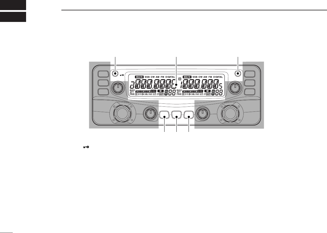
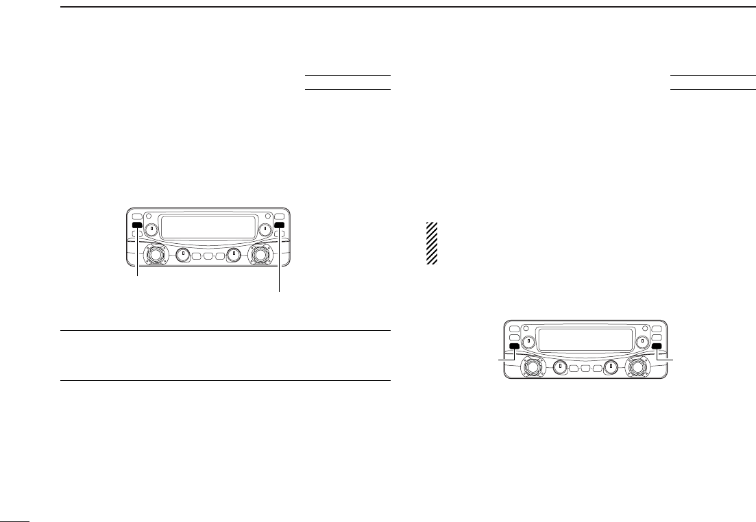
■Front panel— controller
qPOWER KEY [PWR•]
➥Turns the controller power ON and OFF when pushed
and held for 1 sec.
➥Continue to hold this key down for 2 sec. after power
ON to turn the lock function ON and OFF. (p. 15)
wSET•SKIP KEY [SET•SKIP]
➥Enters set mode when pushed. (p. 56)
➥Push and hold for 1 sec. to turn the channel skip setting
ON and OFF for memory/VFO skip scan operation.
(p. ??)
eMONITOR•TONE•TONE SCAN SWITCH
[MONI•T/T-SCAN]
➥Push to turn the monitor function ON and OFF. (p. ??)
➥Push and hold for 1 sec. to enter the tone function se-
lection mode. (pgs. ??, ??)
•Subaudible tone encoder, pocket beep (CTCSS), tone
squelch, pocket beep (DTCS), DTCS squelch or tone func-
tion OFF can be selected.
➥Push and hold for 1 sec. during tone function selection
mode to start the tone scan. (p. ??)
rMODE•SCAN SWITCH [MODE•SCAN]
➥Push and hold for 1 sec. to enter the mode selection
condition. (p. ??)
•Rotate [DIAL] to select the desired operating mode..
➥Starts scan when pushed and held for 1 sec. (p. ??)
•Cancels a scan when pushed during scan.
tATTENUATOR/PRIORITY SWITCH [ATT•PRIO]
➥Push to turn the ATT (Attenuator) function ON and OFF.
MAIN
AGC
S.MW
TS
VFO/MR
MHz
MAIN
NB
S.MW
VFO/MR
TS
MHz
VOLVOL
DIALDIAL
SQLSQL
MONI
T/T-SCAN
MODE
SCAN ATT
PRIO
COMMUNICATIONS RECEIVER
iR2500
PWR SET
SKIP
Function display (pgs. 3, 4)
qw
ert
*The keys wto tare for
the MAIN band only.
4
2
PANEL DESCRIPTION
1
2
3
4
5
6
7
8
9
10
11
12
13
14
15
16
(p. ??)
➥Starts priority watch when pushed for 1 sec. (p. ??)
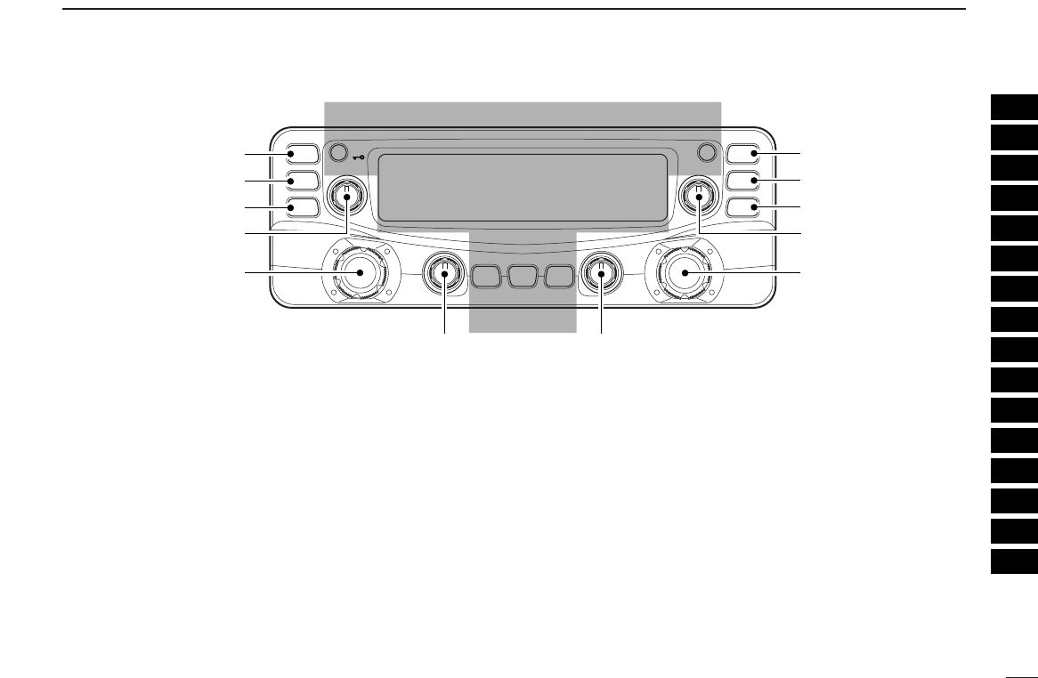
ya MAIN•AGC KEY [MAIN•AGC]
➥Push to select the main band. (p. 11)
➥Push for 1 sec. to turn the AGC (Automatic Gain Con-
trol) function ON and OFF. (p. ??)
yb MAIN•NB KEY [MAIN•NB]
➥Push to select the main band. (p. 11)
➥Push for 1 sec. to turn the NB (Noise Blanker) function
ON and OFF. (p. ??)
u
VFO/MEMORY•MEMORY WRITE KEY [VFO/MR•S.MW]
➥Push to select and toggle VFO, memory and weather
channel* modes. (pgs. 12, 29, 38, 65)
*Weather channels available for USA versions only.
➥Selects a memory channel for programming when
pushed for 1 sec. (pgs. 30, 39, 42)
iMHz TUNING•TUNING STEP [MHz•TS]
➥Selects band selection, 1 MHz or 10 MHz tuning when
pushed. ((p. 9))
➥Push and hold for 1 sec. to enter the tuning step selec-
tion mode. (p. ??)
•Rotate [DIAL] to select the desired tuning step.
oVOLUME CONTROL [VOL] (p. 16)
Adjusts the audio level for relative band.
!0TUNING DIAL [DIAL]
Selects the operating frequency (p. 13), memory channel
(p. 29), the setting of the set mode item and the scanning
direction (p. 41) for the relative band.
!1SQUELCH CONTROL [SQL]
Varies the squelch level for relative band. (p. 16)
MAIN
AGC
S.MW
TS
VFO/MR
MHz
MAIN
NB
S.MW
VFO/MR
TS
MHz
VOLVOL
DIALDIAL
SQLSQL
MONI
T/T-SCAN
MODE
SCAN ATT
PRIO
COMMUNICATIONS RECEIVER
iR2500
PWR SET
SKIP
Left band Right band
oo
yb
u
i
!0
ya
u
i
!0
!1!1
*The same controls for both the left and
right bands are arranged in symmetry.
5
2PANEL DESCRIPTION
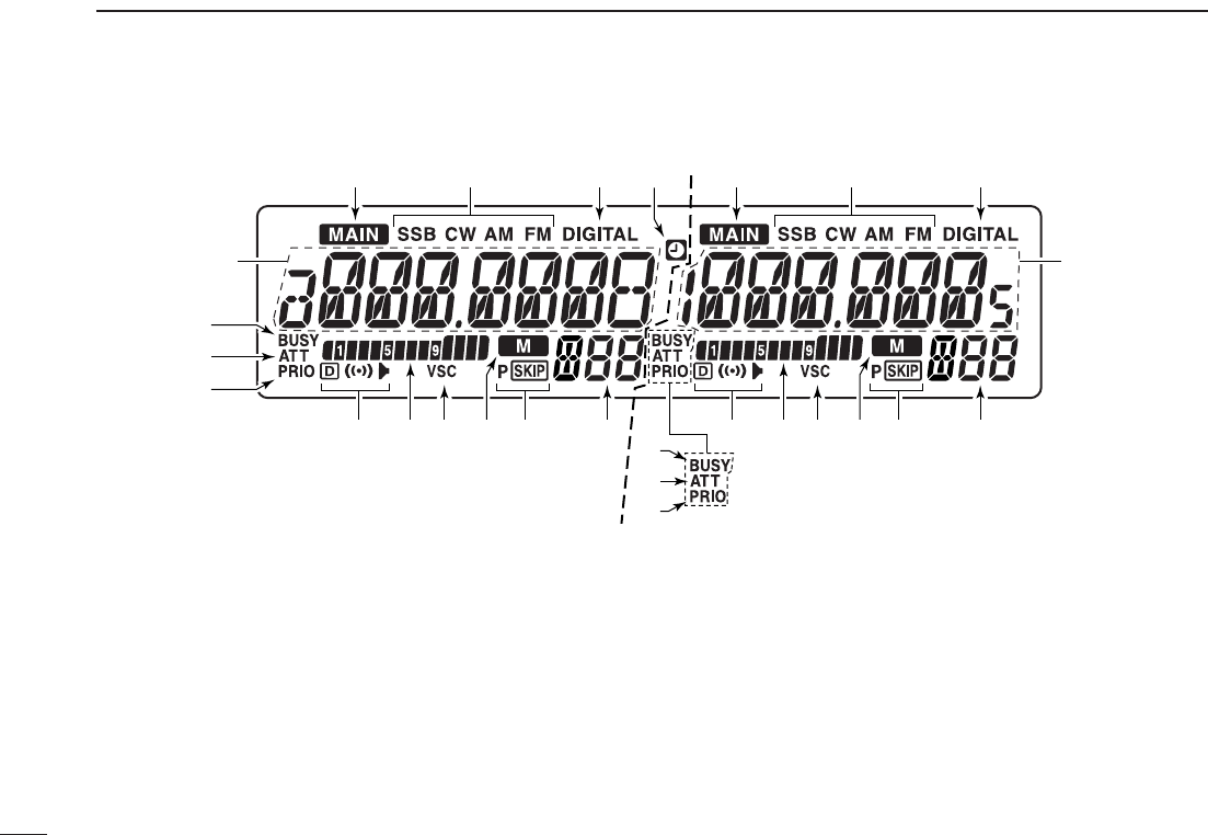
■Function display
qMAIN INDICATOR (p. 11)
Indicate the main band for transmit and function control.
wRECEIVE MODE INDICATORS FOR ANALOG
Shows the selected receive mode.
•SSB (LSB/USB), CW, AM and FM (FM/WFM) are available.
eRECEIVE MODE INDICATOR FOR DIGITAL
Appears while the digital mode is selected..
•DiGITAL mode is available dependes on versions.
rAUTO POWER-OFF INDICATOR ((p. 36))
Appears while the auto power OFF function is in use.
yFREQUENCY READOUT
Shows the operating frequency, channel names, set mode
contents, etc.
•Frequency decimal point blinks while scanning. ((p. 26))
uMEMORY CHANNEL NUMBER INDICATORS
➥Shows the selected memory channel number. ((p. 16))
➥Shows the selected bank initial. ((p. 23))
➥“L” appears when the lock function is activated. ((p. 11))
Left band Right band
t
t
!3
qewqewr
yyuuoo!0!0
!2
!1!1 ii
!4
!3
!4
!2
*The same indications for both the left and right
bands are arranged.

6
2
PANEL DESCRIPTION
2
iSKIP INDICATORS ((p. 28))
➥“~” appears when the displayed memory channel is
specified as a skip channel.
➥“
P
~” appears when the displayed frequency is speci-
fied as a program skip frequency.
iMEMORY INDICATOR (pgs. 12, 29)
Appears when memory mode is selected.
oVSC INDICATOR ((p. 13))
Appears when the VSC function is in use.
!0S-METER INDICATORS
Shows the relative signal strength while receiving signals.
((p. 11))
!1TONE INDICATORS
➥While FM mode operation:
●
●
“”appears while the tone squelch function is in use.
((p. 16))
●
●
“”appears while the DTCS squelch function is in
use. ((p. 16))
➥While DV (Digital) mode operation:
●
●
“”appears while the digital call sign squelch func-
tion is in use. ((p. 16))
●
●
“”appears while the digital code squelch function
is in use. ((p. 16))
➥“S” appears with the “ ” or “ ” indicator while the
pocket beep function is in use.
!2PRIORITY INDICATOR ((p. 30))
Appears while the priority watch is activated; blinks while
the watch is paused.
!3ATT INDICATOR ((p. 12))
Appears when the ATT function is in use.
!4BUSY INDICATOR
➥Appears when a signal is being received or the squelch
is open. ((p. 11))
➥Blinks while the monitor function is in use. ((p. 11))
7
2PANEL DESCRIPTION
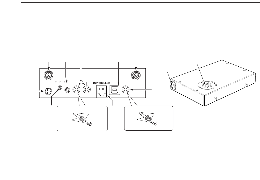
■Rear panel—main unit
Front
Top
Rear Power switch
Speaker
DATA
PACKET 1 USB EXT SP
ANT 1 ANT 2
DC IN
GND
PACKET 2
qwe r t
y
o
iu
2-conductor 3.5 (d) mm (1⁄8˝)/100 kΩ
PACKET jack connection
2-conductor 3.5 (d) mm (1⁄8˝)/8 Ω
EXT SP jack connection
PACKET
GND
SP
GND
8
2
PANEL DESCRIPTION
2
qANTENNA CONNECTOR1 [ANT1]
Connects a 50 Ωantenna with a BNC connector and a 50
Ωcoaxial cable.
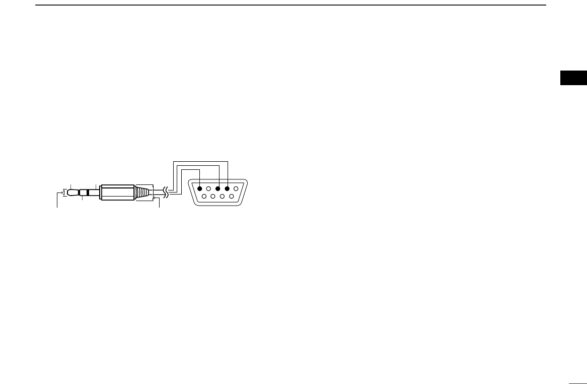
wDATA JACK [DATA]
Connect to a PC or GPS receiver via the RS-232 cable (D-
sub 9 pin) for data communication in the RS-232 format.
ePACKET JACKS [PACKET1/2]
Connect a TNC (Terminal Node Controller), etc. for data
communications. The receiver can receive 9600 bps
packet communication (AFSK).
rUSB CONNECTOR [USB]
Connects to a PC via the supplied USB cable.
tANTENNA CONNECTOR2 [ANT2]
Connects a 50 Ωantenna with a BNC connector and a 50
Ωcoaxial cable.
yEXTERNAL SPEAKER JACK [EXT SP]
Connects an 8 Ωexternal speaker.
•Audio output power is more than 0.5 W.
uCONTROLLER [CONTROLLER]
Connects to a controller via an extension cable.
iPOWER JACK [DC IN]
Accepts 12 V DC ±15% with the supplied DC power cable.
oGROUND TERMINAL [GND]
Connect this terminal to a ground.
Pin 2 (RxD),
Pin 3 (TxD),
Pin 5 (GND)
to [DATA] jack
TxD
2.5(d) mm Less than
10(d) mm
GND
RxD
1
5
69
RS-232
(DB-9 female)
9
SETTING A FREQUENCY
3
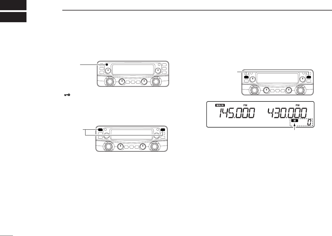
■Preparation
DTurning power ON/OFF
➥Push [PWR•]for 1 sec. to turn power ON and OFF.
DMAIN band
The IC-R2500 can receive 144 MHz and 430(440) MHz band
signals simultaneously.
➥Push the desired band’s [MAIN•AGC] to select the main
band.
•“Q” indicates the main band.
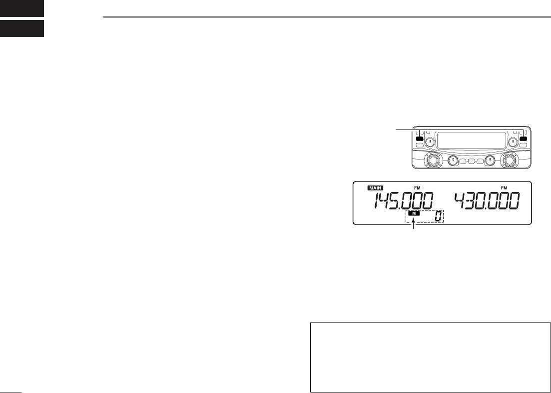
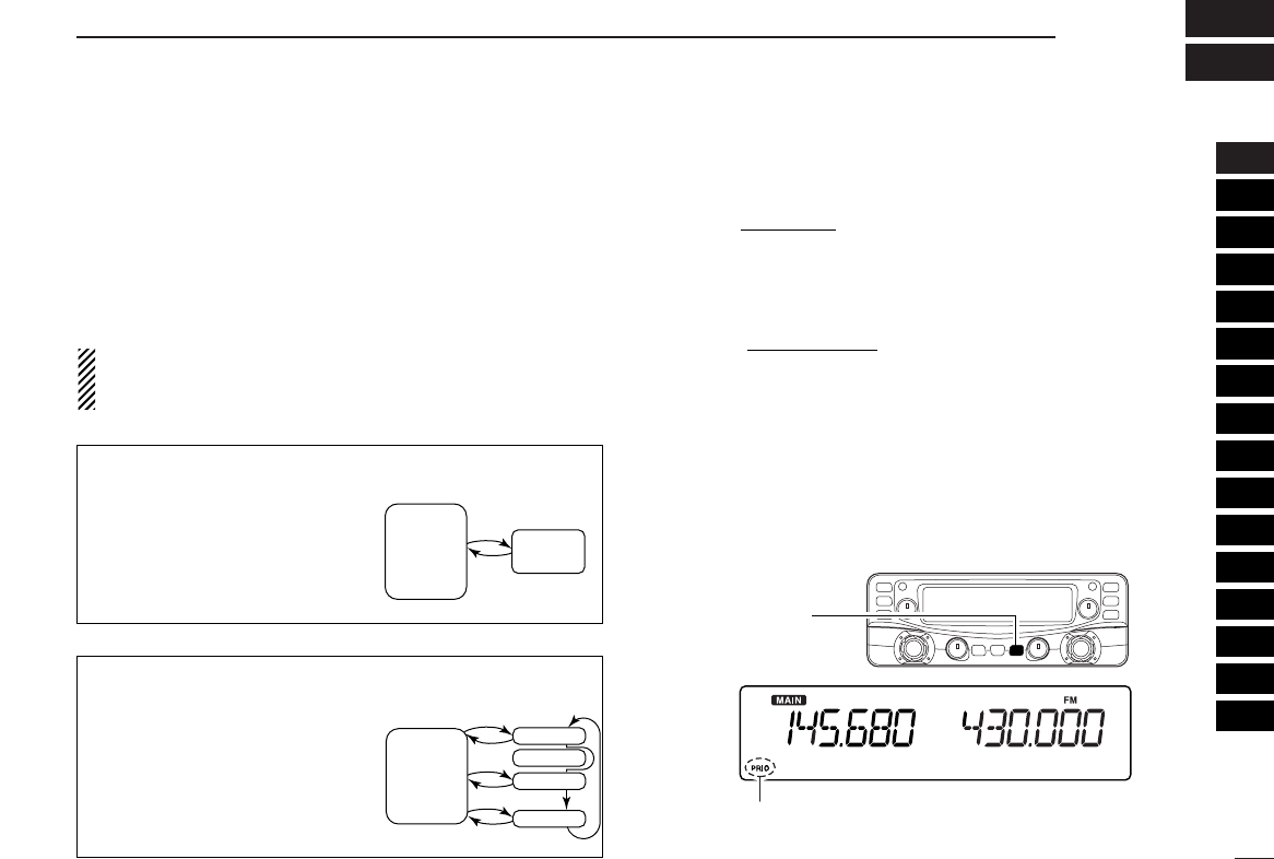
DVFO and memory modes
The receiver has 2 basic operating modes: VFO mode and
memory mode. Select VFO mode first to set an operating fre-
quency.
➥Push the desired band’s [VFO/MR•S.MW] to select VFO
mode.
➥Push [VFO/MR•S.MW] again to select memory mode.
•“!” indicator appears when memory mode is selected.
! indicator appears when
memory mode is selected
[VFO/MR¥S.MW]
Push the desired band’s
[MAIN]
Push [PWR] for 1 sec.
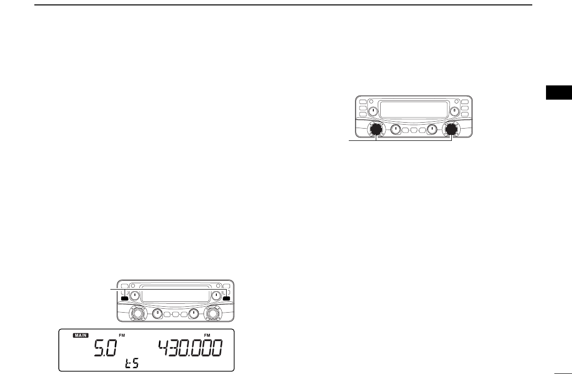
■Tuning step selection
When using the tuning dial to change the frequency, or when
a scan function is activated, the frequency changes in incre-
ments determined by the set tuning step. This can be
changed if desired.
The following tuning step are available.
• 0.01 kHz (10 Hz) • 0.02 kHz (20 Hz) • 0.05 kHz (50 Hz)
• 0.1 kHz (100 Hz) • 0.5 kHz (500 Hz) • 1 kHz
• 2.5 kHz • 5 kHz • 6.25 kHz
• 8.33 kHz • 9 kHz • 10 kHz
• 12.5 kHz • 15 kHz • 20 kHz
• 25 kHz • 30 kHz • 50 kHz
• 100 kHz • 125 kHz • 150 kHz
• 200 kHz • 500 kHz • 1000 kHz (1 MHz)
qPush the desired band’s [MAIN] to select the main band.
•Push the same band’s [VFO/MR•S.MW] to select VFO mode, if
necessary.
wPush and hold [MHz•TS] for 1 sec. to enter tuning step se-
lect mode.
eRotate the same band’s [DIAL] to select the desired tun-
ing step.
rPush [MHz•TS] to exit set mode.
•Or push the same band’s any other keys or common keys (below
the dusplay) to exit tuning step select mode.
[DIAL]
[MHz•TS]
10
3
SETTING A FREQUENCY
3
11
3SETTING A FREQUENCY
■Using the tuning dial
qRotate the desired band’s [DIAL] to set the frequency.
•If VFO mode is not selected, push the same band’s
[VFO/MR•S.MW] to select VFO mode.
•The frequency changes in the selected tuning steps. (p. 14)
wTo change the frequency band or in 1 MHz (10 MHz) steps,
push [MHz•TS], then rotate the band’s [DIAL].
ePush [MHz•TS] to exit tuning step select mode.
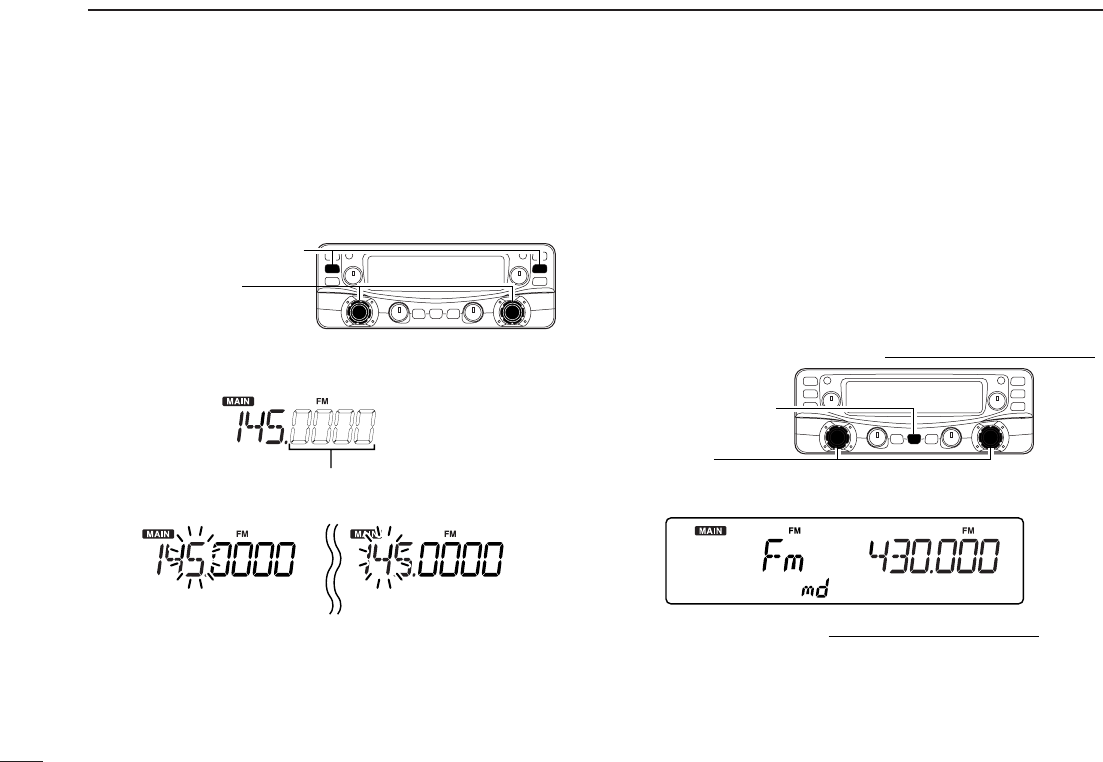
■Receive mode selection
Receive modes are determined by the physical properties of
the radio signals. The receiver has 7 receive modes: LSB
USB, CW, AM, WFM, FM and digital modes. The mode se-
lection is stored independently in each memory channels.
Typically, AM mode is used for the AM broadcast stations
(0.495–1.620 MHz) and air band (118–135.995 MHz), and
WFM is used for FM broadcast stations (76–107.9 MHz).
qPush [MODE•SCAN] to enter receive mode select mode.
wRotate [DIAL] to select the desired mode.
ePush any switch to exit receive mode select mode.
[DIAL]
[MODE•SCAN]
While the band selection mode is selected,
the digits below 100 kHz disappear.
While 1 MHz tuning step is
selected, the 1 MHz digit
blinks.
While 10 MHz tuning step is
selected, the 10 MHz digit
blinks.
Push [VFO/MR•S.MW]
Rotate [DIAL]
12
4
BASIC OPERATION
1
2
3
4
5
6
7
8
9
10
11
12
13
14
15
16
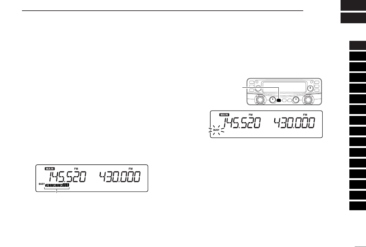
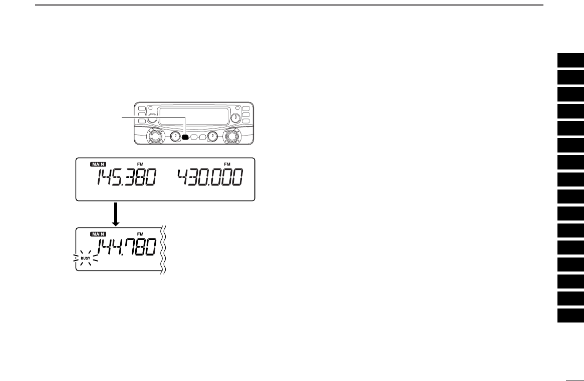
■Receiving
qSet the audio level for the main band.
➥Push the desired band’s [MAIN].
➥Push [MONI•T/T-SCAN] to open the squelch.
➥Rotate the main band’s [VOL] to adjust the audio level.
➥Push [MONI•T/T-SCAN] to close the squelch.
wSet the squelch level.
➥Rotate the main band’s [SQL] fully counterclockwise in
advance, then rotate [SQL] clockwise until the noise
just disappears.
eSet the operating frequency in the main band. (pgs. 11–13)
•When interference is received, push [ATT•PRIO] to turn the at-
tenuator function ON. (p. 17)
rWhen receiving a signal on the set frequency, squelch
opens and the receiver emits audio.
•“BUSY” appears and the S-meter shows the relative signal
strength for the received signal.
■Monitor function
This function is used to listen to weak signals without disturb-
ing the squelch setting or to open the squelch manually even
when mute functions such as the tone squelch are in use.
➥Push [MONI•T/T-SCAN] for 1 sec. to open the squelch.
•Push [MAIN] to select the desired band (left or right) as the main
band in advance.
•“BUSY” blinks.
•Push [MONI•T/T-SCAN] again to cancel the function.
[MONI•T/T-SCAN]
Appears when receiving a signal.
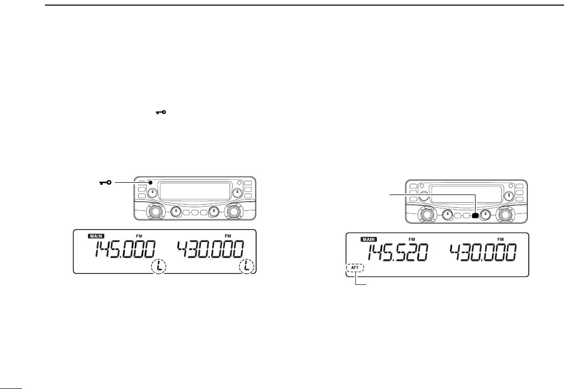
■Lock functions
To prevent accidental frequency changes and unnecessary
function access, use the lock function.
➥Continue to hold [SET• ] down for 2 sec. after power
ON to turn the lock function ON and OFF.
•[MONI•T/T-SCAN] (monitor function only), [VOL], [SQL],
[MAIN•AGC] (main band selection only) and [MAIN•NB] (main
band selection only) can be used while the channel lock function
is in use.
■Attenuator function
The attenuator prevents a desired signal from distorting when
very strong signals are near the desired frequency or when
very strong electric fields, such as from a broadcasting sta-
tion, are near your location. The attenuator gain is about 20
dB and this function can be activated on 1300 MHz or below.
➥Push [ATT•PRIO] momentarily to toggle the attenuator
function ON and OFF.
•“ATT” appears when the attenuator function is in use.
[ATT•PRIO]
Appears
[PWR• ]
2 “L”s appear while the lock function is activated.
13
4BASIC OPERATION
14
4
BASIC OPERATION
1
2
3
4
5
6
7
8
9
10
11
12
13
14
15
16
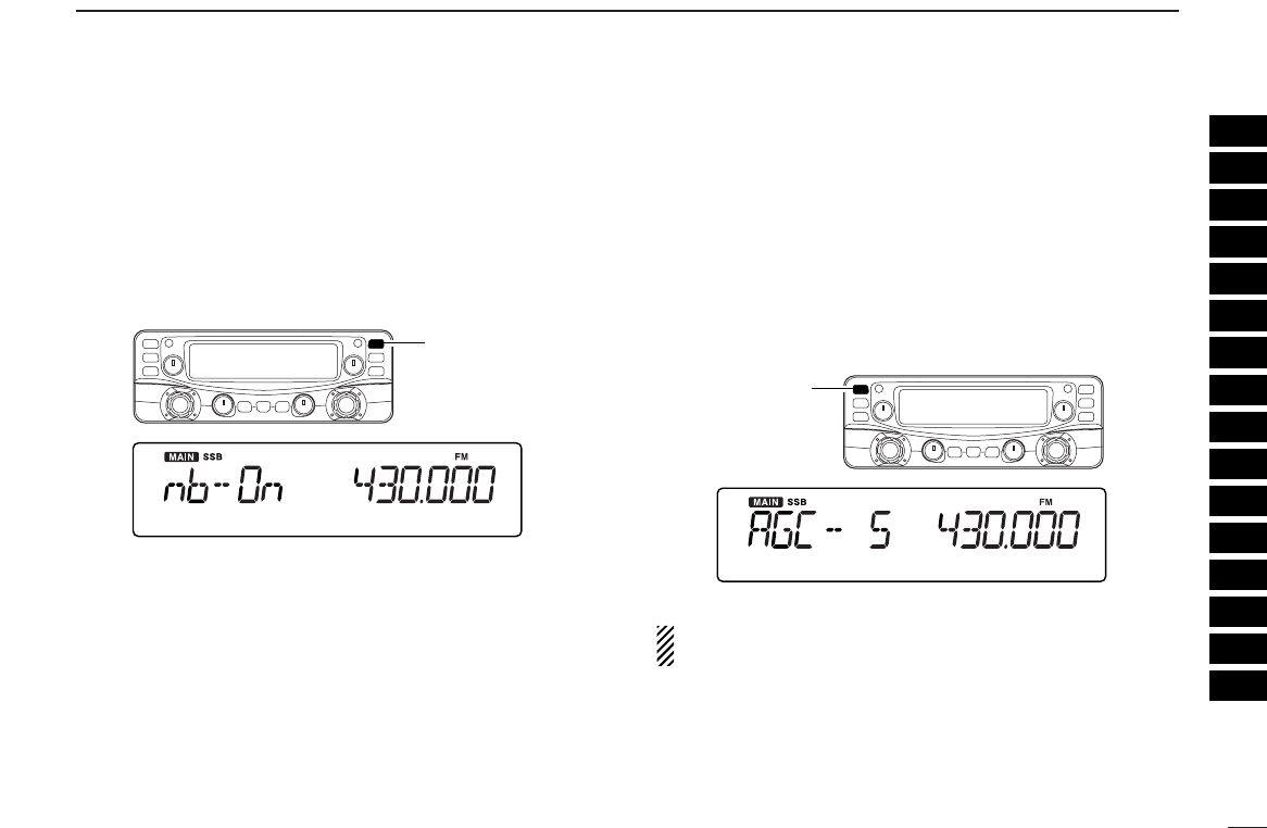
■NB function
The NB (noise blanker) function removes pulse-type noise
when SSB, CW or AM mode is selected.
➥Push and hold [MAIN•NB] for 1 sec. to toggle the NB func-
tion ON and OFF.
•“nb-On” or “nb-OF” appears for a moment when the NB function
is turned ON or OFF, respectively.
■AGC function
The AGC (Automatic Gain Control) function controls receiver
gain to produce a constant audio output level even when the
received signal strength is varied by fading, etc. This AGC
slow function is selectable for SSB, CW or AM mode.
➥Push and hold [MAIN•AGC] for 1 sec. to toggle the AGC
function Slow and Fast.
•“AGC-S” or “AGC-F” appears for a moment when the AGC func-
tion is selected Slow or Fast, respectively.
While in FM or WFM mode, the AGC function is fixed as
Fast and AGC Slow cannot be selected.
[MAIN•AGC]
[MAIN•NB]
15
4BASIC OPERATION
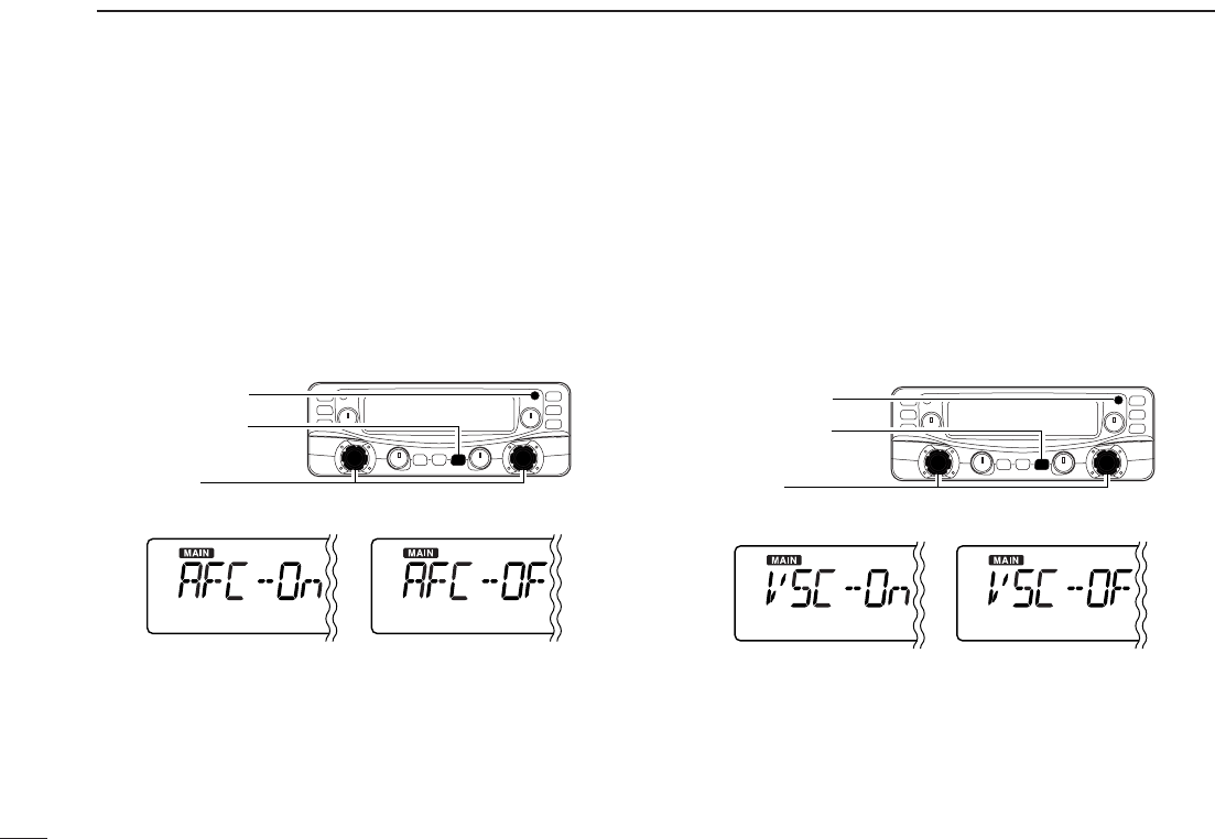
■AFC function [
The AFC (Automatic Frequency Control) function tunes the
displayed frequency automatically when an off-center fre-
quency is received. It activates in FM mode and only when
the selected IF filter is 6 kHz or 15 kHz.
qSelect FM mode.
wPush [SET•SKIP] to enter set mode.
ePush [SET•SKIP] or [ATT•PRIO] several times until “AFC”
appears.
rRotate [DIAL] to toggle the AFC function ON and OFF.
tPush any switch for main band to exit set mode.
■VSC function [
The VSC (Voice Squelch Control) function opens the squelch
only when receiving a modulated signal. This function is very
useful while scanning, the VSC pauses only when modulated
signals are received. Scanning continues when unmodulated
or beat signals are received.
qPush [SET•SKIP] to enter set mode.
wPush [SET•SKIP] or [ATT•PRIO] several times until “VSC”
appears.
eRotate [DIAL] to toggle the VSC function ON and OFF.
rPush any switch for main band to exit set mode.
[SET•SKIP]
[DIAL]
[ATT•PRIO]
[SET•SKIP]
[DIAL]
[ATT•PRIO]
16
4
BASIC OPERATION
1
2
3
4
5
6
7
8
9
10
11
12
13
14
15
16
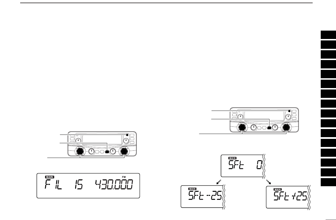
■IF filter selection [
The receiver has 2 to 4 passband width IF filters for each
mode. Selectable passband width are from 3, 6, 15, 50 and
230 (depending on the selected mode).
• Selectable passband width for each mode.
SSB mode : 3 (2.8 kHz) or 6 kHz
CW mode : 3 (2.8 kHz) or 6 kHz
AM mode : 3 (2.8 kHz), 6 kHz, 15 kHz or 50 kHz
WFM mode: 50 kHz or 230 kHz
FM mode : 6 kHz, 15 kHz or 50 kHz
qPush [SET•SKIP] to enter set mode.
wPush [SET•SKIP] or [ATT•PRIO] several times until “VSC”
appears.
eRotate [DIAL] to select the desired IF passband width.
rPush any switch for main band to exit set mode.
■IF shift function [
The IF shift function electronically changes the passband fre-
quency of the IF (Intermediate frequency) and cuts out higher
or lower frequency components of the IF to reject interfer-
ence. This function is available when the receive mode is se-
lected SSB or CW mode, and shifts the IF frequency up to
±25 steps in 1 step (50 Hz).
qPush [SET•SKIP] to enter set mode.
wPush [SET•SKIP] or [ATT•PRIO] several times until “SFt”
appears.
eRotate [DIAL] to set the shifting direction and frequency
range.
rPush any switch for main band to exit set mode.
Center position
(default)
Hi
g
hest
Lowest
[SET•SKIP]
[DIAL]
[ATT•PRIO]
[SET•SKIP]
[DIAL]
[ATT•PRIO]
17
4BASIC OPERATION
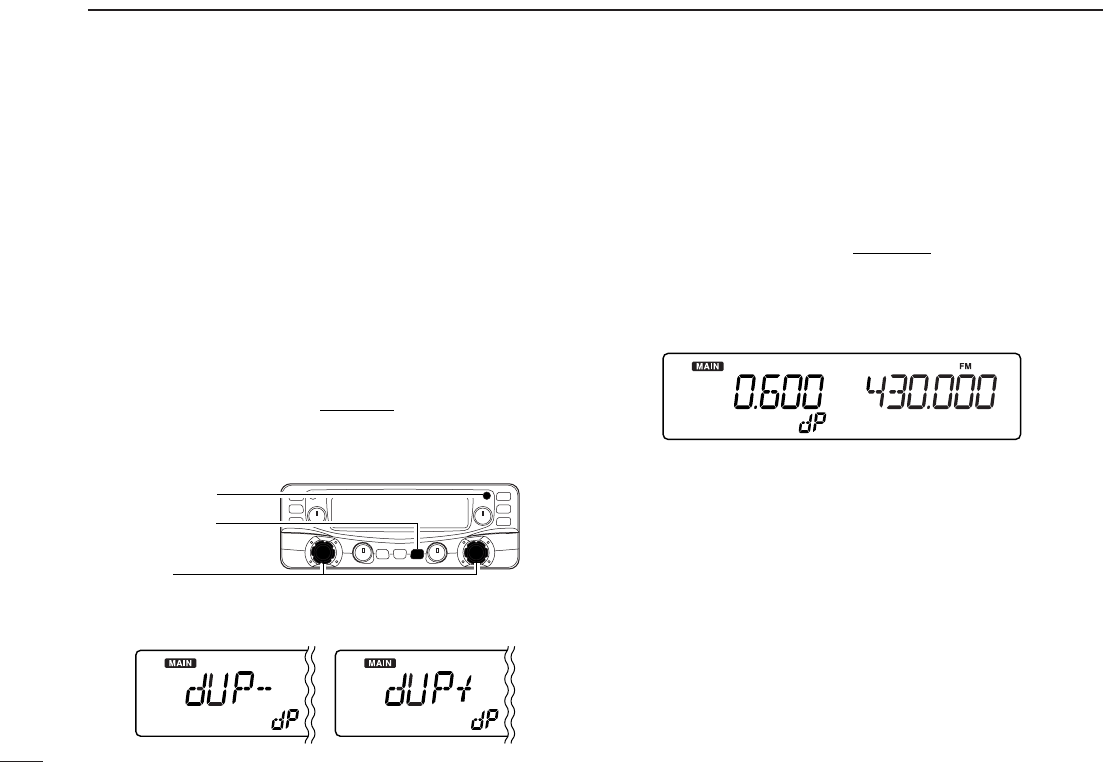
Duplex communication uses two different frequencies for
transmitting and receiving. Generally, duplex is used in com-
munication through a repeater, some utility communications,
etc.
During duplex operation, the transmit station frequency is
shifted from the receive station frequency by the offset fre-
quency. Repeater information (offset frequency and shift di-
rection) can be programmed into memory channels. ((p. 16))
DDSetting [
qPush [SET•SKIP] to enter set mode.
wPush [SET•SKIP] or [ATT•PRIO] several times until the
duplex direction setting item “OFF dP,” “DUP– dP” or “DUP+
dP” appears.
eRotate [DIAL] to select the duplex direction, “DUP– dP” or
“DUP+ dP.”
rPush [SET•SKIP] once to select the offset frequency set-
ting item.
tRotate [DIAL] to set the desired offset frequency within
0.000–1000.000 MHz range.
•The tuning step, selected in VFO mode, is used for setting.
•Push [MHz• TS] then rotate [DIAL] to change the frequency in
10 MHz steps, or push again then rotate [DIAL] to change the
frequency in 1 MHz steps. (Each push toggles 1MHz, 10 MHz
or selected tuning steps.)
yPush any switch for main band to exit set mode.
[SET•SKIP]
[DIAL]
[ATT•PRIO]
■Duplex operation
18
4
BASIC OPERATION
1
2
3
4
5
6
7
8
9
10
11
12
13
14
15
16
DDOperation
qSet the receive station frequency (repeater output frequency).
wPush [MONI•T/T-SCAN] to monitor the transmit station fre-
quency (repeater input frequency) directly.
[MONI¥T/T-SCAN]
Frequency shifts
the offset frequency
19
MEMORY OPERATION
5
■General description
The receiver has 1100 memory channels including 100 scan
edge memory channels (50 pairs) for storage of often-used
frequencies. And a total of 21 memory banks, A to H, J to R,
T, U, W and Y are available for storing groups of frequencies,
etc. Up to 100 channels can be assigned into a bank.
DDMemory channel contents
The following information can be programmed into memory
channels:
•Operating frequency ((p. 9))
•Receive mode ((p. 10))
•Duplex direction (DUP+ or DUP–) with an offset fre-
quency ((p. 15))
•Tone squelch or DTCS squelch ON/OFF ((p. 33))
•Tone squelch frequency or DTCS code with polarity
((p. 38))
•Scan skip information ((p. 28))
■Memory channel selection
qPush the desired band’s [VFO/MR•S.MW] once or twice
to select memory mode.
•“M” indicator appears.
w
Rotate the same band’s [DIAL] to select the desired mem-
ory channel.
•Programmed memory channels only can be selected.
! indicator appears when
memory mode is selected
[VFO/MR¥S.MW]
If memory banks or weather channels* mode appears when
pushed [VFO/MR•S.MW] at step q, push [MHz•TS] and ro-
tate [DIAL] to select “bAnk --,” then push any switches for
main band or common switches to exit from settings.
*Available for USA/CANADA versions only.
20
5
MEMORY OPERATION
5
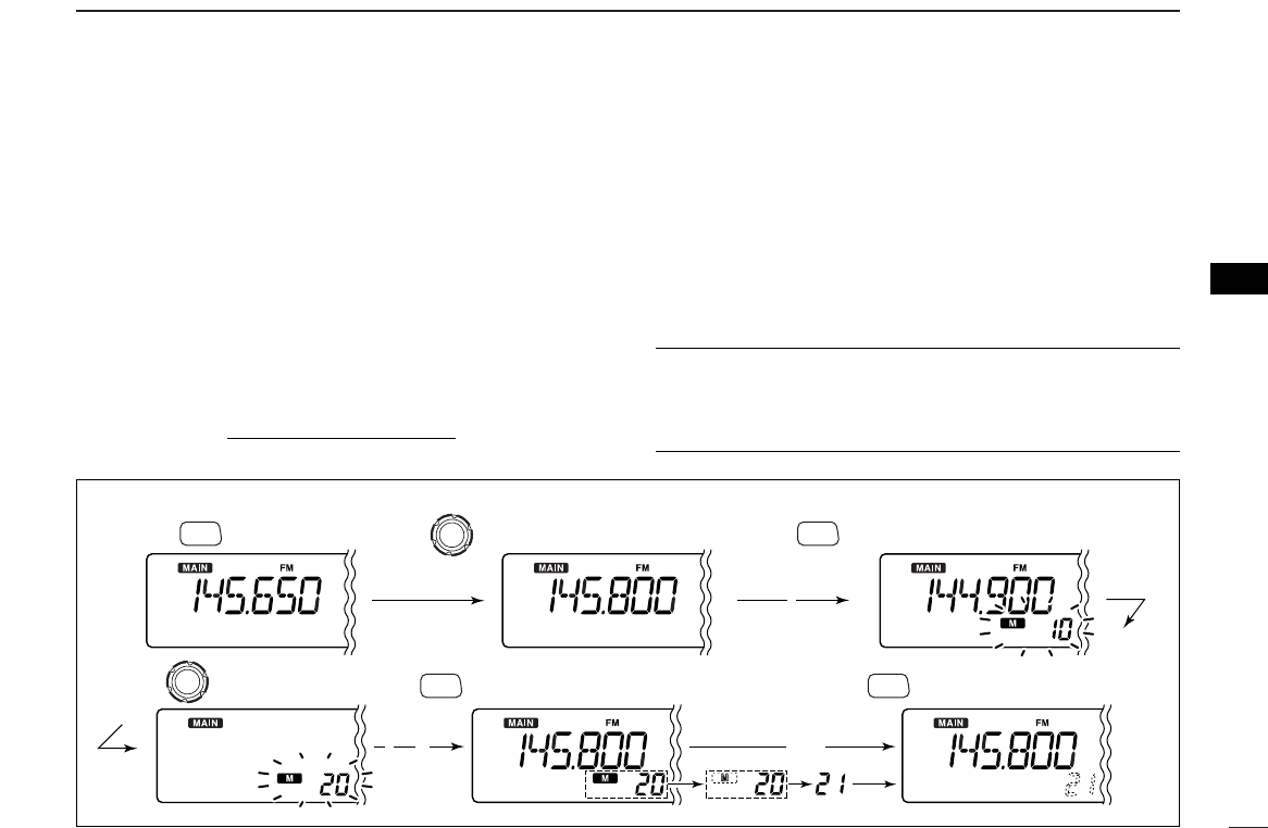
■Programming a memory channel
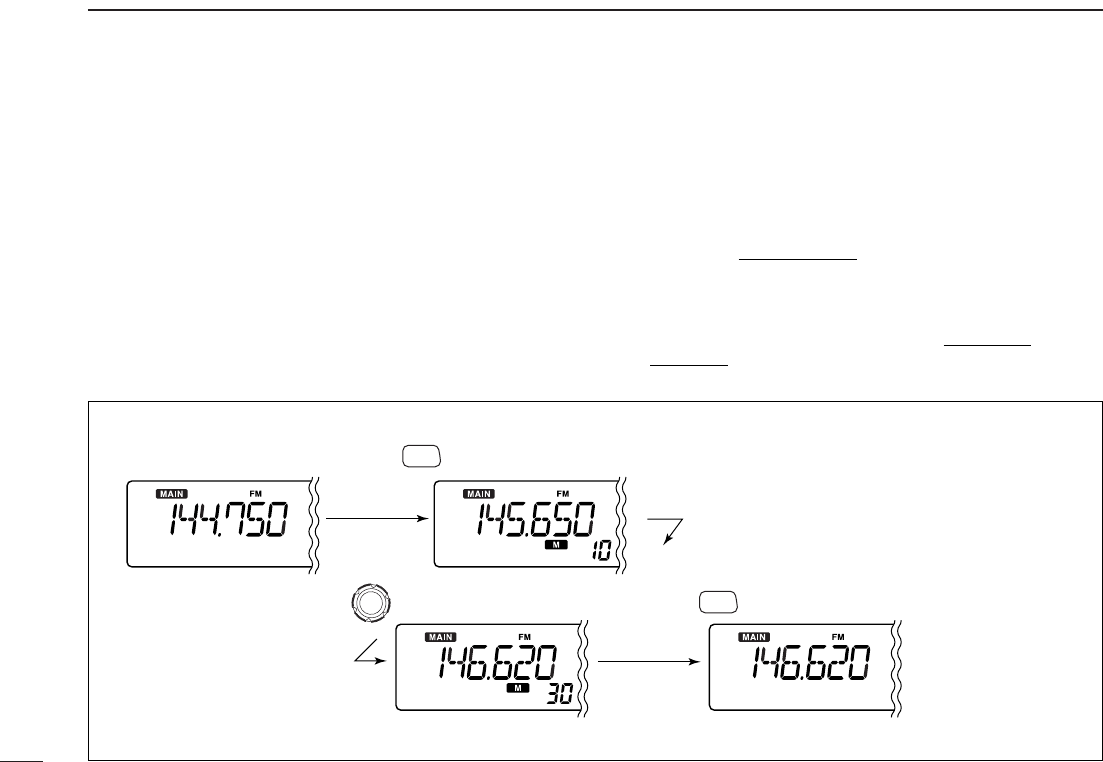
[EXAMPLE]: Programming 145.800 MHz into memory channel 20 (blank channel).
Push Rotate for setting frequency, etc. Push for 1 sec.
Rotate Push for 1 sec. and continue to push
➠
Beep
“
Beep
Beep
Beep
“
“
“
“
“
Beep
Beep
“
“
S.MW
VFO/MR
S.MW
VFO/MR
S.MW
VFO/MR
Release S.MW
VFO/MR
VFO settings, including the set mode contents such as sub-
audible tone frequency, offset, scan skip information can be
programmed into a memory channel.
qSet the desired frequency in the desired band (left or right).
➥Push the desired band’s [VFO/MR•S.MW] once or twice
to select VFO mode.
➥Set the frequency using the same band’s [DIAL].
➥Set other data (e.g. tone frequency, duplex information,
etc.) if required.
wPush and hold the same band’s [VFO/MR•S.MW] for
1sec. to enter select memory write mode.
•“!” indicator and the memory channel number blink.
eRotate [DIAL] to select the memory channel to be pro-
grammed.
•Memory channels not yet programmed are blank.
rPush and hold [VFO/MR•S.MW] for 1 sec. to program.
•3 beeps sound
•Memory channel number automatically increases when contin-
uing to push [VFO/MR•S.MW] after programming.
✔CONVENIENT
Memory programming can be performed in versatile ways
e.g. memory channel to the same (or different) memory chan-
nel, etc.
21
5MEMORY OPERATION
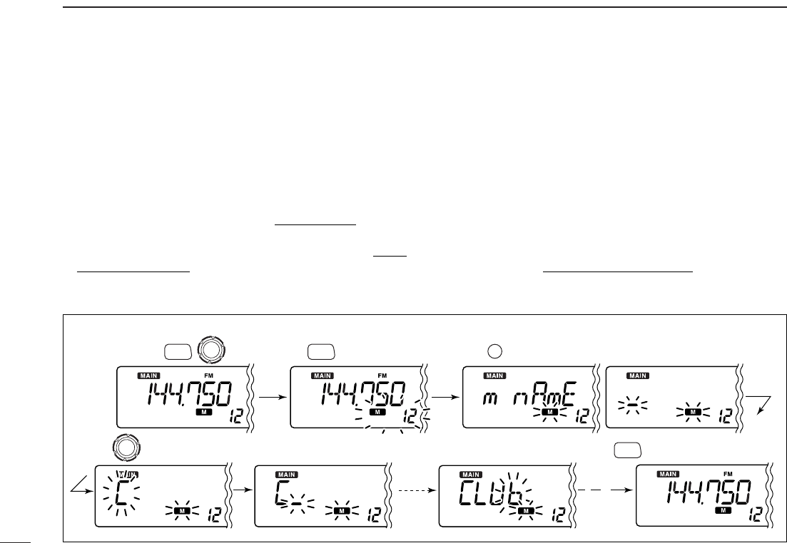
[EXAMPLE]: Programming “CLUB” into memory channel 12.
Select
memory channel Push for 1 sec.
Rotate Push for 1 sec.
Beep
Beep
Beep
“
“
“
“
“
S.MW
VFO/MR
S.MW
VFO/MR
S.MW
VFO/MR Push twice
SET
SKIP
Repeat the
previous
steps.
E
ach memory channel can be programmed with an alphanu-
meric channel name for easy recognition and can be indicated
independently by channel. Names can be a maximum of 6
characters— see the table on next page for available charac-
ters.
qSelect the desired memory channel to be programmed.
➥Push [VFO/MR•S.MW] to select memory mode, then ro-
tate [DIAL] to select the desired memory channel.
wPush and hold [VFO/MR•S.MW] for 1 sec. to enter select
memory write mode.
•“!” indicator and the memory channel number blink.
ePush [SET•SKIP] several times to select the memory
name programming condition, “m nAmE.”
•Frequency readouts disappear and a cursor blinks.
rRotate [DIAL] to select the desired character.
•The selected character blinks.
tPush [ATT•PRIO] to move the cursor to the right.
•Repeat pushing [ATT•PRIO] to return to the first digit.
yRepeat steps rand tuntil the desired channel names
are displayed.
uPush and hold [VFO/MR•S.MW] for 1 sec. to program the
name and exit select memory write mode.
■Programming channel names
22
5
MEMORY OPERATION
1
2
3
4
5
6
7
8
9
10
11
12
13
14
15
16
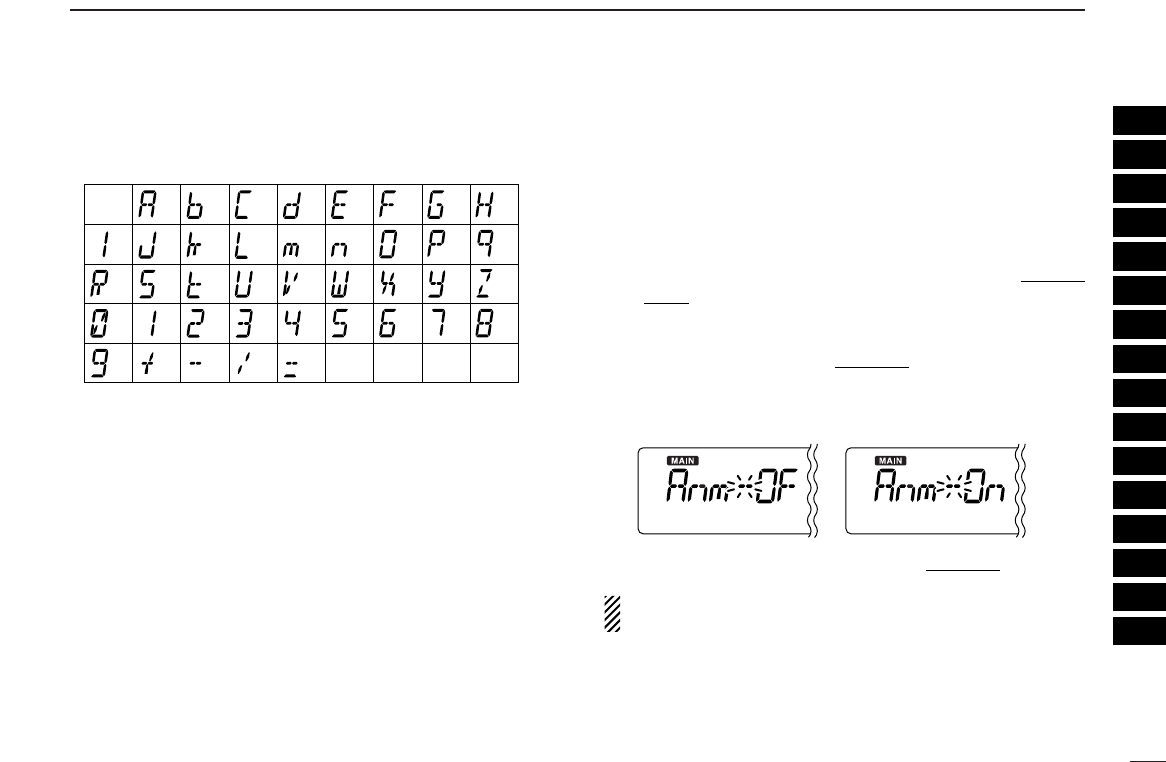
• Available characters DDTo indicate the channel name [
The channel name indication can be set for independent
memory channels.
qSelect the desired memory channel in the main band.
➥Push [VFO/MR•S.MW] once or twice to select memory
mode, then rotate [DIAL] to select the desired memory
channel.
•“!” and memory channel number appear.
wPush [SET•SKIP] to enter set mode.
ePush [SET•SKIP] or [ATT•PRIO] several times to select
“Anm” item.
rRotate [DIAL] to turn the memory name indication ON.
tPush any switch for main band to exit set mode.
NOTE: When no memory name is programmed, the stored
frequency is displayed.
(1)
(B)
(L)
(V)
(+)
(2)
(C)
(
M
)
(
W
)
(–)
(3)
(
D
)
(N)
(X)
(/)
(4)
(E)
(O)
(Y)
(=)
(5)
(F)
(P)
(Z)
(6)
(G)
(
Q
)
(space)
(7)
(
H
)
(
R
)
(8)
(I)
(S)
(9)
(J)
(T)
(0)
(A)
(
K
)
(U)
23
5MEMORY OPERATION
[EXAMPLE]: Transferring memory channel 30 contents to VFO.
Push to select memory mode.
Rotate for selecting memory channel. Push for 3 sec.
S.MW
VFO/MR
S.MW
VFO/MR
This function transfers a memory channel’s contents to VFO
(or another memory channel). This is useful when searching
for signals around a memory channel frequency and for re-
calling the subaudible tone frequency etc.
DMemory➪VFO
qSelect the desired band’s (left or right) memory channel to
be transferred.
➥Push the desired band’s [VFO/MR•S.MW] several times
to select memory mode, then rotate the same band’s
[DIAL] to select the desired memory channel.
•“!” and memory channel number appear.
wPush and hold [VFO/MR•S.MW] for 3 sec. to transfer the
selected memory channel contents to VFO mode.
•VFO mode is selected automatically.
■Copying memory contents
24
5
MEMORY OPERATION
5
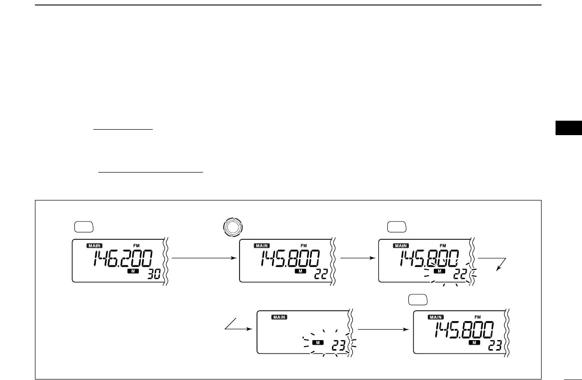
DMemory➪memory
qSelect the desired band’s (left or right) memory channel to
be transferred.
➥Push the desired band’s [VFO/MR•S.MW] several times
to select memory mode, then rotate the same band’s
[DIAL] to select the desired memory channel.
•“!” and memory channel number appear.
wPush and hold the same band’s [VFO/MR•S.MW] for 1
sec. to enter select memory write mode.
•“!” and memory channel number blink.
eRotate [DIAL] to select the target memory channel.
•Scan edge channels, 0A/0B to 49A/49B can also be selected.
rPush and hold [VFO/MR•S.MW] for 1 sec. to transfer the
selected memory channel contents to the target memory.
•The targeted memory and transferred contents are indicated.
[EXAMPLE]: Transferring memory channel 22 contents to channel 23.
Push to select memory mode.
Select the target channel.
Rotate for selecting memory channel.
Push for 1 sec.
S.MW
VFO/MR
S.MW
VFO/MR
Push for 1 sec.
S.MW
VFO/MR
5MEMORY OPERATION
25
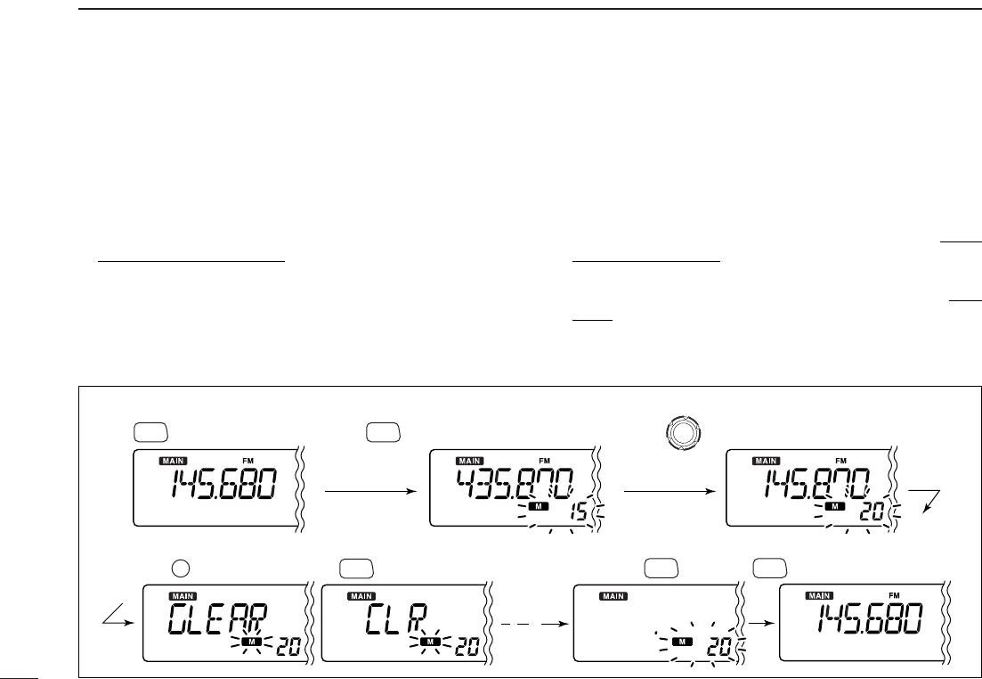
Contents of programmed memories can be cleared (blanked),
if desired.
qPush [VFO/MR•S.MW] to select VFO mode in the main
band.
wPush the same band’s [VFO/MR•S.MW] for 1 sec. to enter
select memory write mode.
•“!” indicator and the memory channel number blink.
eRotate the same band’s [DIAL] to select the memory
channel to be cleared.
•Memory channels not yet programmed are blank.
rPush [SET•SKIP] three times to select “CLEAR,” then
push and hold [VFO/MR•S.MW] for 1 sec.
•3 beeps sound.
•The cleared channel changes to blank channel
•“!” and the memory channel number blink continuously.
tPush the same band’s [MAIN] or [MHz•TS] to exit select
memory write mode, or repeat steps eand rto clear
other channel.
yPush the same band’s [VFO/MR•S.MW] to return to VFO
mode.
☞NOTE: Be careful!— the contents of cleared memories
CANNOT be recalled.
[EXAMPLE]: Clearing memory channel 20.
Push to select VFO. Rotate for selecting memory channel.Push for 1 sec.
S.MW
VFO/MR S.MW
VFO/MR
S.MW
VFO/MR
Push any switch for main band
other than , then push to return to VFO.
S.MW
VFO/MR S.MW
VFO/MR
Push three times, then push for 1 sec.
SET
SKIP
Beep
Beep
Beep
“
“
“
“
“
■Memory clearing
5
MEMORY OPERATION
26
5
■Memory bank setting [
The IC-R2500 has a total of 21 banks (A to H, J to R, T, U,
W, Y). Regular memory channels, 0 to 999, may assigned
into the desired bank for easy memory management.
qSelect the desired memory channel.
➥Push [VFO/MR•S.MW] to select memory mode in the
main band, then rotate the same band’s [DIAL] to se-
lect the desired memory channel.
•“!” and memory channel number appear.
wPush and hold the same band’s [VFO/MR•S.MW] for 1
sec. to enter select memory write mode.
•“!” indicator and the memory channel number blink.
ePush [SET•SKIP] once to select “bAnk.”
rRotate [DIAL] to select the desired bank and bank chan-
nel.
•Push [ATT•PRIO] to toggle the bank or bank channel selection.
•Banks A to H, J to R, T, U, W and Y are available.
•Vacant bank channel numbers are only be displayed.
tPush and hold [VFO/MR•S.MW] for 1 sec. to program the
bank and exit select memory write mode.
Bank selection Bank channel selection
After [SET•SKIP]
released
[SET•SKIP]
[DIAL]
[ATT•PRIO]
[VFO/MR•S.MW]
27
5MEMORY OPERATION
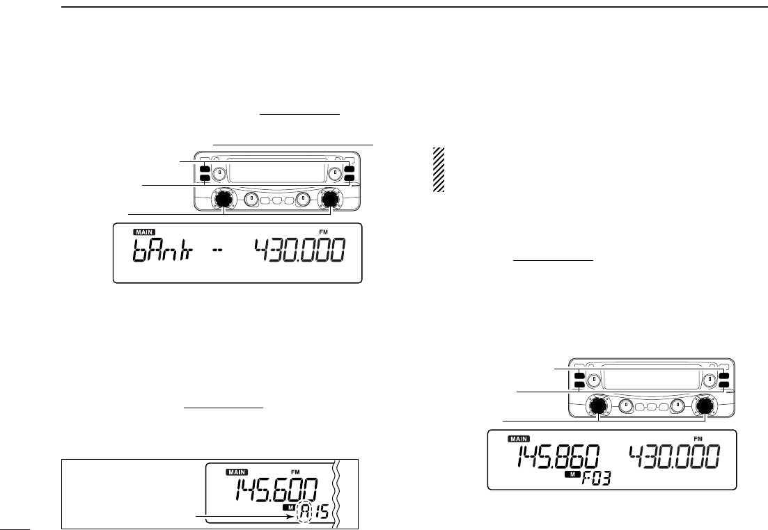
■Memory bank selection
qPush [VFO/MR•S.MW] to select memory mode in the de-
sired band (left or right).
wPush [MHz•TS] to enter memory type selection mode.
eRotate [DIAL] to select the desired bank (A to H, J to R, T,
U, W or Y).
•Only programmed banks are displayed.
rPush any switch for main band or common switch to set
the bank indication.
•Bank’s indicator appears at top of the memory channel.
tRotate [DIAL] to select the contents in the bank.
yTo return to regular memory mode, repeat steps w–rand
select “bAnk --” at step e.
• Memory bank indication
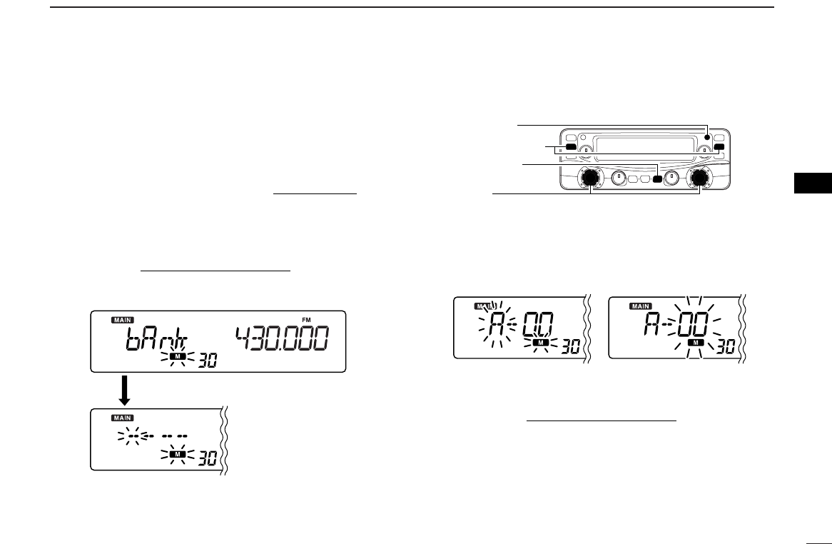
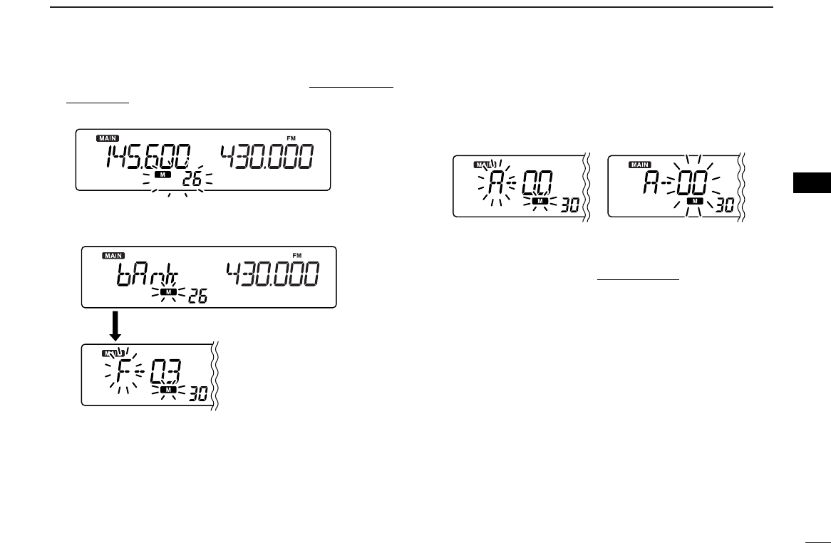
■Transferring bank contents
The bank contents of programmed memory channels can be
cleared or transferred to another bank.
INFORMATION: Even if the memory bank contents are
cleared, the memory channel contents still remain pro-
grammed.
qSelect the desired bank contents to be transferred or
erased from the bank in the main band.
➥Push the main band’s [VFO/MR•S.MW] several times
to select memory mode.
➥Push the same band’s [MHz•TS] then rotate the same
band’s [DIAL] to select the desired memory bank.
•Bank’s indicator appears at top of the memory channel.
➥Push any switch for main band or common switch to se-
lect the bank then rotate [DIAL] to select the desired
contents.
[DIAL]
[MHz•TS]
[VFO/MR•S.MW]
Bank indicator appears
[DIAL]
[MHz•TS]
[VFO/MR•S.MW]
28
5
MEMORY OPERATION
5
wPush [VFO/MR•S.MW] for 1 sec. to enter select memory
write mode.
•“!” indicator and the memory channel number blink.
ePush [SET•SKIP] once to select “bAnk.”
rRotate [DIAL] to select the desired bank indicator to trans-
fer or erase.
•Push [ATT•PRIO] to toggle the bank or bank channel selection.
•Select “– –” indication when erasing the contents from the bank.
•Vacant bank channel numbers are only be displayed.
tPush and hold [VFO/MR•S.MW] for 1 sec. to program the
bank and return to regular memory mode.
yRepeat steps qto tfor transferring or erasing an an-
other banks contents.
Bank selection Bank channel selection
After [SET•SKIP]
released
Memory channel blinks
29
SCAN OPERATION
6
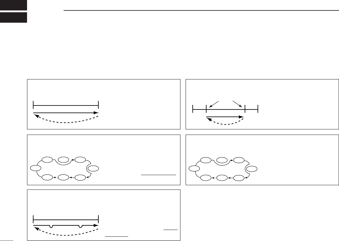
■Scan types
Scanning searches for signals automatically and makes it
easier to locate new stations for contact or listening purposes. There are 5 scan types and 4 resume conditions to suit your
operating needs.
FULL SCAN ((p. 26)) Repeatedly scans all frequen-
cies over the entire band.
Some frequency ranges are
not scanned according to the
frequency coverage of the re-
ceiver’s version.
10
kHz 3299.9999
MHz
Scan
Jump
ALL/SELECTED BANK
SCAN ((p. 26))
Repeatedly scans all bank
channels or selected bank
channels. The skip scan is
also available.
SKIP
SKIP
A99 A03
A00 A01 A02
A04
A98
A05
PROGRAMMED SCAN
((p. 26))
Repeatedly scans between
two user-programmed fre-
quencies. Used for checking
for frequencies within a speci-
fied range such as repeater
output frequencies, etc.
Band
edge xxA xxB
Band
edge
Scan edges
Scan
Jump
MEMORY (SKIP) SCAN
((p. 26))
Repeatedly scans memory
channels except those set as
skip channel. Skip channels
can be turned ON and OFF
by pushing and holding
[SET•SKIP] in memory mode.
SKIP
SKIP
M 0 M 4
M 1 M 2 M 3
M 5
M 199
M 6
FREQUENCY/MEMORY
SKIP FUNCTION ((p. 28))
Skips unwanted frequencies
or channels that inconve-
niently stop scanning. This
function can be turned ON
and OFF by pushing and
holding [SET•SKIP] in mem-
ory mode.
Band
edge Band
edge
Scan
SKIP SKIP
Jump
30
6
SCAN OPERATION
1
2
3
4
5
6
7
8
9
10
11
12
13
14
15
16
■Scan start/stop
DPreparation
Scan resume condition ((p. 29)); program the scan edges
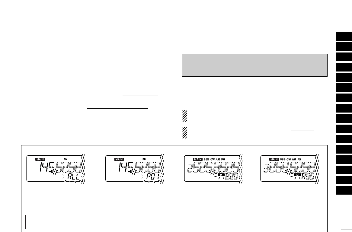
((p. 27)); program two or more memory channels ((p. 17)); set
skip settings ((p. 28)), if desired.
DOperation
qPush [VFO/MR•S.MW] once or twice to select VFO mode
for full/programmed scan; or to select memory mode for
memory/bank scan.
•Select the desired bank in memory type selection mode for bank
scan.
wSet the squelch level to the point where noise is just muted.
ePush and hold [MODE•SCAN] for 1 sec. to start the scan.
•To change the scanning direction, rotate [DIAL].
•The memory channel readout blinks the scan type as below.
rPush [SET•SKIP] (or [ATT•PRIO]) to switch full and pro-
grammed scan (P00 to P49), if VFO is selected in step q.
tTo stop the scan, push [MODE•SCAN].
About the scanning steps: The selected tuning step in
each frequency band (in VFO mode) is used during scan.
The bank-link setting can be changed in set mode. See
((p. 40)) for details.
• During full scan • During programmed scan • During memory scan • During bank scan
Indicates scan edge channels.
• P01 stands for 01A/01B
• P00 to P49 are available when
they are programmed, and
switches with [SET•SKIP].
Indicates bank channel.
Push [SET•SKIP] to se-
lect full (ALL) or program-
med scan (P00–P49) in
sequence.
While pushing and holding [MODE•SCAN], rotate [DIAL]
also to select full (ALL) or programmed scan (P00–P49).
NOTE: When SSB, CW, AM, FM, WFM or Digital mode
frequencies are programmed into memory channels disorderly,
memory scan takes a lot of time (very slow). Because
changing modes takes a time. In this case, assign the SSB,
CW, AM, FM, WFM or Digital mode frequencies into the
separate bank respectively. And using the bank scan is helpful.
IMPORTANT!: To perform memory or bank scan, two or
more memory/bank channels MUST be programmed, oth-
erwise the scan will not start.
31
6SCAN OPERATION
Scan edges can be programmed in the same manner as
memory channels. Scan edges are programmed into scan
edges, 0A/0B to 49A/49B, in memory channels.
qPush the desired band’s [VFO/MR•S.MW] once or twice
to select VFO mode.
wSet the edge frequency of the desired frequency range:
➥Set the frequency using the same band’s [DIAL].
➥Set other data (e.g. tone squelch, etc.), if desired.
ePush and hold the same band’s [VFO/MR•S.MW] for
1sec. to enter select memory write mode.
•“!” indicator and the memory channel number blink.
rRotate [DIAL] to select one of scan edge channel, 0A to
49A.
tPush and hold [VFO/MR•S.MW] for 1 sec. to program.
•3 beeps sound and VFO mode is automatically selected.
•Scan edge 0B to 49B is automatically selected when continuing
to hold [VFO/MR•S.MW] after programming.
yTo program a frequency for the other pair of scan edges,
0B to 49B, repeat steps wto r.
•If the same frequency is programmed into a pair of scan edges,
programmed scan will not function.
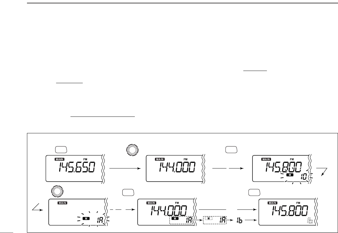
[EXAMPLE]: Programming 144.000 MHz into scan edge 1A.
Push Rotate for setting frequency, etc. Push for 1 sec.
Rotate Push for 1 sec. and continue to push
➠
Beep
“
Beep
Beep
Beep
“
“
“
“
“
Beep
Beep
“
“
S.MW
VFO/MR
S.MW
VFO/MR
S.MW
VFO/MR
Release S.MW
VFO/MR
■Scan edges programming
32
6
SCAN OPERATION
6
DSkip channel/frequency setting
You can set the selected memory channel as a skip channel
which is skipped during memory skip scan. In addition, it can
be set as a skip channel for both memory skip scan and fre-
quency skip scan. These are useful to speed up the scan in-
terval.
qSelect a memory channel.
➥Push the main band’s [VFO/MR•S.MW] once or twice
to select memory mode, then rotate the same band’s
[DIAL] to select the desired memory channel to be a
skip channel.
•“!” and memory channel number appear.
wPush and hold [SET•SKIP] for 1 sec. several times to set
the skip condition.
• (no indication): The channel is scanned during scan.
• ~: The channel is skipped during scan.
•
P
~: The channel is skipped during scan and the pro-
grammed frequency is skipped during VFO scan,
such as programmed scan.
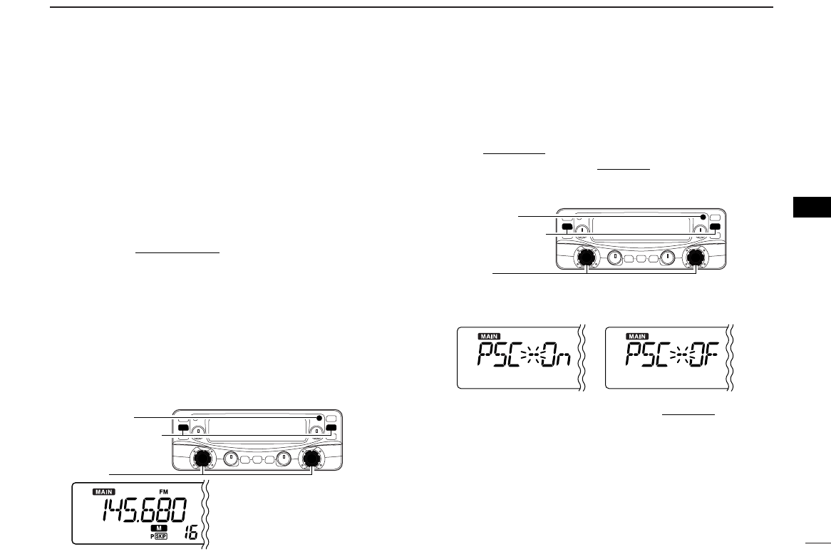
DSkip scan setting [
qPush the main band’s [VFO/MR•S.MW] once or twice to
select VFO mode.
qPush [SET•SKIP] to enter set mode.
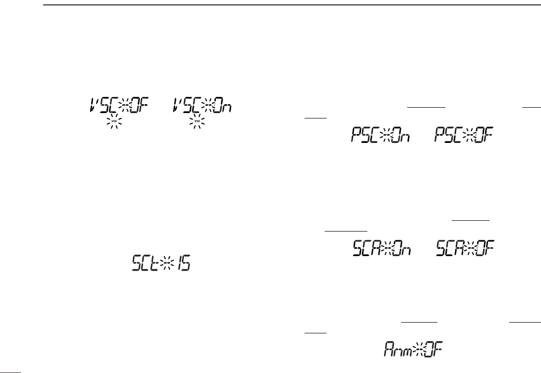
wPush [SET•LOCK] or [ATT•PRIO] several times until
“PSC” appears.
eRotate [DIAL] to toggle the skip scan function ON and
OFF.
rPush any switch for main band to exit set mode.
tThen start the scan to activate the skip scan (memory skip
scan or frequency skip scan).
[DIAL]
[VFO/MR•S.MW]
[SET•SKIP]
[DIAL]
[VFO/MR•S.MW]
The display shows that
memory channel 16 is
set as a skip channel.
[SET•SKIP]
■Skip scan
33
6SCAN OPERATION
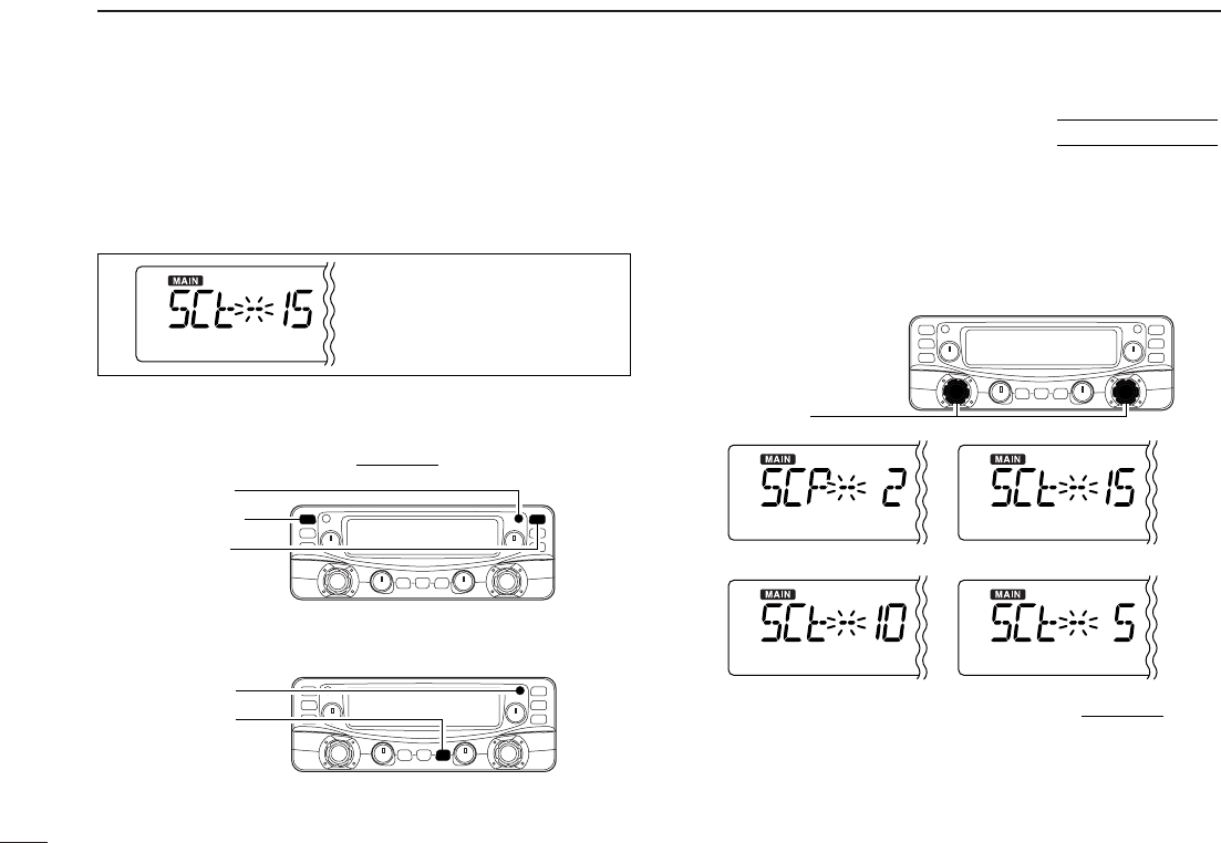
The scan resume condition can be selected as timer or pause
scan. The selected resume condition is also used for priority
watch. (p. 47)
qPush
[MAIN•AGC] (or [MAIN•NB])
to select the desired
band (left or right) as the main band.
wPush
[SET•
SKIP
]
to enter set mode.
ePush
[SET•
SKIP
]
or [ATT•PRIO] several times until “SCt”
or “SCP” appears.
rRotate the main band’s [DIAL] to set the desired timer:
•“SCP-2” : Scan pauses until the signal disappears and then
resumes 2 sec. later.
•“SCt-15” : Scan pauses 15 sec. while receiving a signal.
•“SCt-10” : Scan pauses 10 sec. while receiving a signal.
•“SCt-5” : Scan pauses 5 sec. while receiving a signal.
tPush any switch for the main band to exit set mode.
[DIAL]
[ATT•PRIO]
[SET•SKIP]
[MAIN•AGC]
[MAIN•NB]
[SET•SKIP]
The display shows that the
scan will resume 15 sec. after
it stops.
■Scan resume condition
USING
SET MODE
34
7
PRIORITY WATCH
1
2
3
4
5
6
7
8
9
10
11
12
13
14
15
16
■Priority watch types
Priority watch checks for signals on the frequency every
5sec. while operating on a VFO frequency or scanning. The
receiver has two priority watch types to suit your needs.
The watch resumes according to the selected scan resume
condition. See ((p. 29)) for details.
NOTE: If the pocket beep function is activated, the receiver
automatically selects the tone/DTCS squelch function
when priority watch starts.
■Priority watch operation
qPush the main band’s [VFO/MR•S.MW] once or twice to
select VFO mode; then set an operating frequency.
wSet the watching channel(s).
For memory channel watch:
Select the desired memory channel.
For memory scan watch:
Select memory mode, or the desired bank group; then,
push and hold [MODE•SCAN] for 1 sec. to start memory
scan or bank scan.
ePush and hold [ATT•PRIO] for 1 sec. to start the watch.
•The receiver checks the memory/bank channel(s) every 5 sec.
•The watch resumes according to the selected scan resume con-
dition. ((p. 29))
•While the watch is pausing, pushing and holding [ATT•PRIO] for
1 sec. resumes the watch manually.
rPush and hold [ATT•PRIO] for 1 sec. to stop the watch.
[ATT•PRIO]
“PRIO” appears
MEMORY CHANNEL WATCH
While operating on a VFO fre-
quency, priority watch checks for
a signal on the selected memory
channel every 5 sec.
•Amemory channel with skip infor-
mation can be watched.
5 sec.
VFO
frequency Memory
channel
MEMORY SCAN WATCH
While operating on a VFO fre-
quency, priority watch checks for
signals on each memory chan-
nel in sequence.
•The memory skip function and/or
memory bank scan is useful to
speed up the scan.
5 sec.
VFO
frequency
SKIP
Mch 000
Mch 001
Mch 001
Mch 999
35
POCKET BEEP AND TONE SQUELCH
8
This function uses subaudible tones for calling and can be
used as a “common pager” to inform you that someone has
called while you were away from the receiver.
DWaiting for a call from a specific station
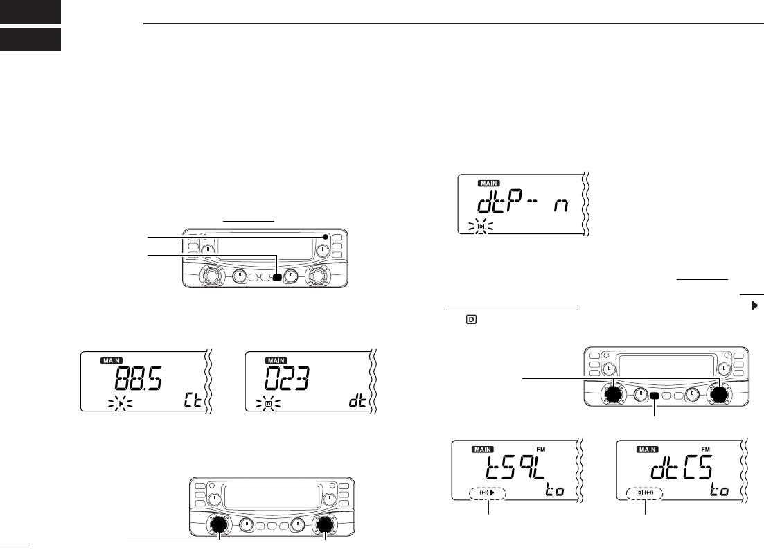
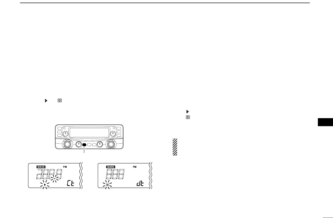
qSet the operating frequency in FM mode.
wPush
[SET•
SKIP
]
to enter set mode in the main band.
ePush
[SET•
SKIP
]
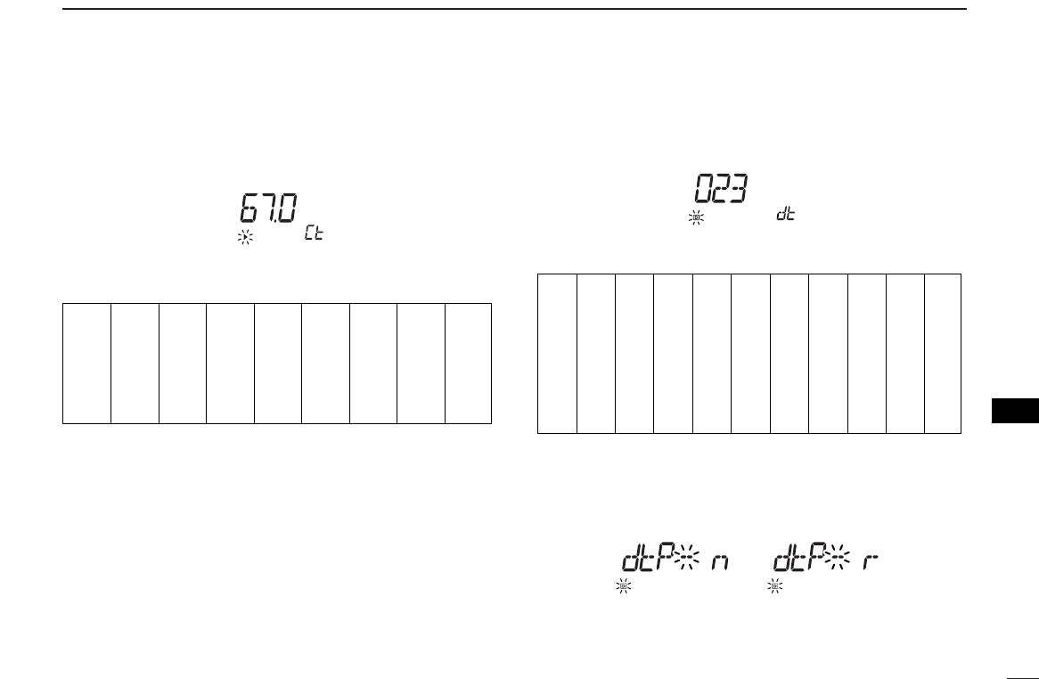
or [ATT•PRIO] several times until “Ct”
(when selecting the tone squelch) or “dt”(when selecting
the DTCS squelch) appears.
rRotate the main band’s [DIAL] to select the desired tone
frequency or DTCS code.
tWhen operating the pocket beep function with DTCS code
squelch, push
[SET•SKIP] once then r
otate [DIAL] to se-
lect the DTCS polarity.
yPush any switch for the main band to exit set mode.
uPush and hold [MONI•T/T-SCAN] for 1 sec. to enter tone
squelch selection mode, then rotate [DIAL] until “S”
or “ S” appears to turn the pocket beep function ON
with tone squelch or DTCS squelch, respectively.
[MONI•T/T-SCAN]
[DIAL]
Appears when the pocket beep
with tone squelch is turned ON. Appears when the pocket beep
with DTCS squelch is turned ON.
DTCS polarity setting
[DIAL]
Tone squelch frequency setting DTCS code setting
[ATT•PRIO]
[SET•SKIP]
■Pocket beep operation
36
8
POCKET BEEP AND TONE SQUELCH
1
2
3
4
5
6
7
8
9
10
11
12
13
14
15
16
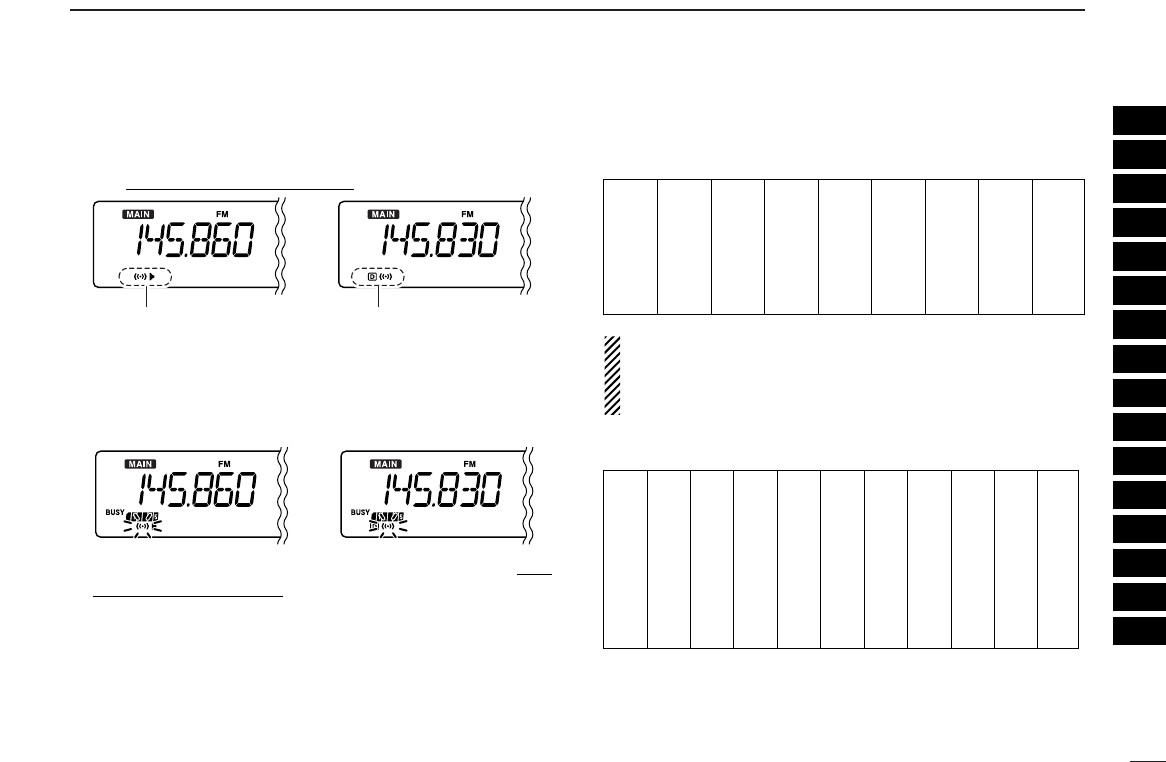
iPush any switch for the main band or common switch to
exit tone squelch selection mode.
oWhen a signal with the matched tone is received, the re-
ceiver emits beep tones and blinks “S”.
•Beep tones sound for 30 sec. and “S” blinks. To stop the
beeps and blinking manually, push any switch.
!0 Push and hold [MONI•T/T-SCAN] for 1 sec. to enter tone
squelch selection mode, then rotate [DIAL] to cancel the
tone squelch or DTCS squelch function.
•“oFF” is selected for turning the function OFF.
DAvailable tone frequency list
NOTE: The receiver has 51 tone frequencies and conse-
quently their spacing is narrow compared to units having
38 tones. Therefore, some tone frequencies may receive
interference from adjacent tone frequencies.
DAvailable DTCS code list
DCalling a waiting station using pocket beep
Asubaudible tone matched with the station’s CTCSS tone fre-
quency or 3-digit DTCS code with polarity is necessary. Use
the tone squelch on the next page ((p. 33)).
023
025
026
031
032
036
043
047
051
053
125
131
132
134
143
145
152
155
156
162
245
246
251
252
255
261
263
265
266
271
356
364
365
371
411
412
413
423
431
432
506
516
523
526
532
546
565
606
612
624
054
065
071
072
073
074
114
115
116
122
165
172
174
205
212
223
225
226
243
244
274
306
311
315
325
331
332
343
346
351
445
446
452
454
455
462
464
465
466
503
627
631
632
654
662
664
703
712
723
731
732
734
743
754
Appears when the pocket beep
with tone squelch is activated. Appears when the pocket beep
with DTCS squelch is activated.
67.0
69.3
71.0
71.9
74.4
77.0
79.7
82.5
85.4
88.5
91.5
94.8
097.4
100.0
103.5
107.2
110.9
114.8
118.8
123.0
127.3
131.8
136.5
141.3
146.2
151.4
156.7
159.8
162.2
165.5
167.9
171.3
173.8
177.3
179.9
183.5
186.2
189.9
192.8
196.6
199.5
203.5
206.5
210.7
218.1
225.7
229.1
233.6
241.8
250.3
254.1
37
10 POCKET BEEP AND TONE SQUELCH
The tone or DTCS squelch opens only when receiving a sig-
nal with the same pre-programmed subaudible tone or DTCS
code, respectively. You can silently wait for the specified sig-
nal using the same tone.
qSet the operating frequency in FM mode.
wProgram the CTCSS tone frequency or DTCS code in set
mode. ((p. 31))
ePush and hold [MONI•T/T-SCAN] for 1 sec. to enter
tone squelch selection mode, then rotate [DIAL] until “ ”
or “ ” appears in the function display.
rWhen a signal with the matched tone is received, the
squelch opens and the receiver emits audio.
•When the received signal includes an unmatched tone, the
squelch does not open. However, the S-meter indicator shows
the received signal strength.
•To open the squelch manually, push [MONI•T/T-SCAN].
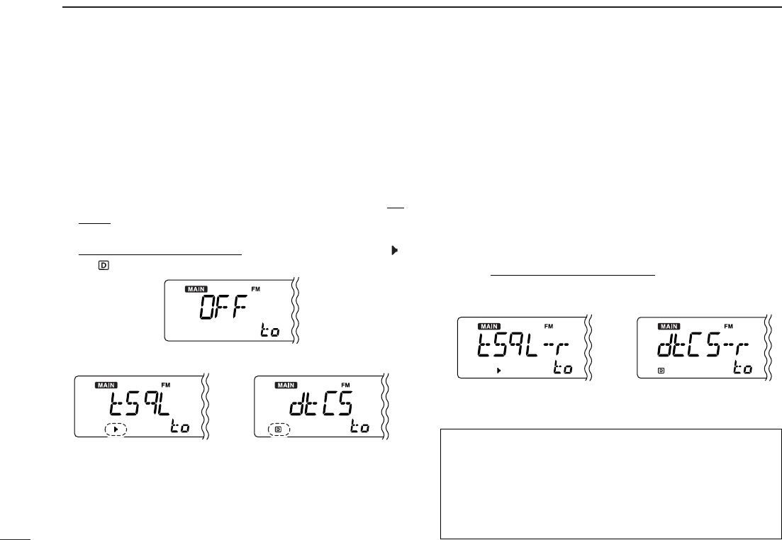
tTo cancel the tone squelch or DTCS squelch function, re-
peat steps euntil “oFF” appears, then push any switch.
DReverse action for tone or DTCS squelch
➥Enter tone squelch selection mode as described in steps
qto eas shown left, then rotate [DIAL] to select either
reverse action for the tone or DTCS squelch as below.
for DTCSfor Tone squelch
Tone OFF setting
DTCS settingTone squelch setting
■Tone/DTCS squelch operation
How does the Reverse action work?
When the reverse action is selected for either the tone
squelch, “tSqL-r,” or DTCS squelch, “dtCS-r,” and a signal
with the matched tone (or DTCS) is received, the squelch
closes, and the receiver mutes the signal. You can listen in
the signals any other than the specified one, if it’s with tone.
38
10
POCKET BEEP AND TONE SQUELCH
10
■Tone scan
By monitoring a signal that is being operated with pocket
beep, tone or DTCS squelch function, you can determine the
tone frequency or DTCS code necessary to open a squelch.
qSet the desired operating frequency or memory channel to
be checked for a tone frequency or code.
wPush and hold [MONI•T/T-SCAN] for 1 sec and rotate
[DIAL] to select the tone type, tone squelch or DTCS, to
be scanned.
•Either “ ” or “ ” appears.
ePush and hold [MONI•T/T-SCAN] for 1 sec. to start the
tone scan.
•To change the scanning direction, rotate [DIAL].
rWhen the CTCSS tone frequency or 3-digit DTCS code is
matched, the squelch opens and the tone frequency is
temporarily programmed into the selected condition such
as memory channel.
•The tone scan pauses when a CTCSS tone frequency or 3-digit
DTCS code is detected.
•The decoded CTCSS tone frequency or 3-digit DTCS code is
used for the tone decoder depending on the selected tone con-
dition or type in step w.
-“ ”: CTCSS tone decoder
-“ ”: DTCS tone decoder
tPush any switch for the main band or common switch to
stop the scan.
NOTE: The decoded tone frequency is programmed tem-
porarily when a memory is selected. However, this will be
cleared when the memory channel is re-selected.
[MONI•T/T-SCAN]
During CTCSS frequency scan During DTCS code scan
†Appears when accessing set mode from VFO mode only.
‡Appears when accessing set mode from memory mode only.
: Push
: Push
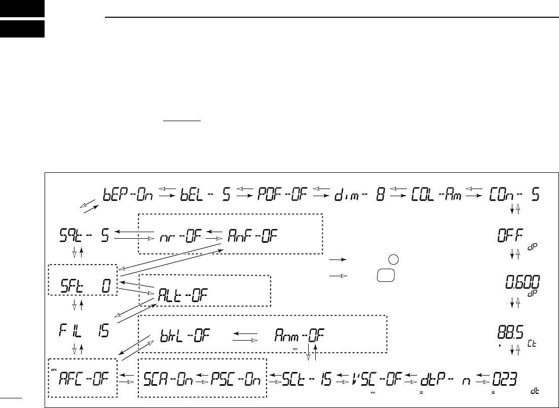
• Weather alert*1
When the UT-106 is installed
• Display dimmer• Auto power OFF• Key-touch beep • Beep output level • Display color
• TSQL frequency
• DTCS code• DTCS polarity
• Offset frequency
• Duplex direction
• Display contrast
• Scan resume timer • VSC function
• Bank link function‡
• AFC function*2
• NR function*4• ANF function*4
• Squelch delay
• IF filter
• IF shift*3
• Program skip†
• Scan skip area†
• Memory name‡
Memory mode
only
FM mode only VFO mode only
SSB/CW
mode only
USA/CANADA
versions only
*1Available for USA/CANADA versions only.
*2Appears while in FM mode only.
*3Appears while in SSB/CW mode only.
*4Appears when the UT-106 is selected.
SET
SKIP
ATT
PRIO
■Set mode
•Set mode operation
qPush the desired band’s
[MAIN]
to select the main band.
wPush
[SET•
SKIP
]
to enter set mode.
ePush
[SET•SKIP]
or [ATT•PRIO] to select the desired
item.
rRotate the main band’s [DIAL] to select the condition or
value.
tPush any switch for main band or common switch other
than
[SET•SKIP]
or [ATT•PRIO] to exit set mode.
•Set mode items
■Set mode items
39
SET MODE
9
40
9
SET MODE
1
2
3
4
5
6
7
8
9
10
11
12
13
14
15
16
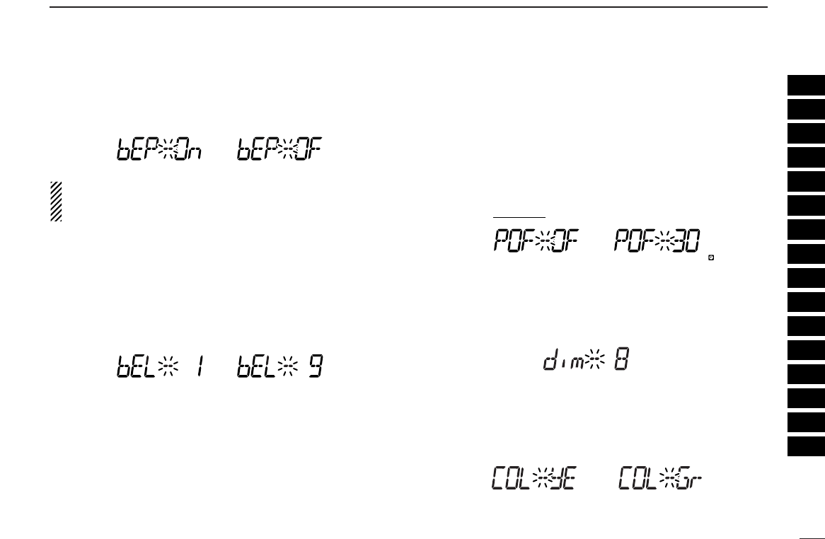
DDKey-touch beep
The key-touch beep can be turned OFF for silent operation.
(default: ON)
Even when this item is set to OFF, the power-on beep and
pocket beep function still sound. The power-on beep can
not be set to OFF.
DDBeep output level
Adust the beep level from 1 to 9 for key-touch beep, power-on
beep and pocket beep function. (default: 5)
When the previous set mode item “bEP” is set to OFF, this
setting level is not effective for key-touch beep.
DDAuto power OFF
The receiver can be set to automatically turn OFF with a beep
after a specified period when no key operations are per-
formed.
30 min., 1 hour, 2 hours and OFF can be specified. The spec-
ified period is retained even when the receiver is turned OFF
by the auto power OFF function. To cancel the function, select
“OF” in this set mode.(default: OFF)
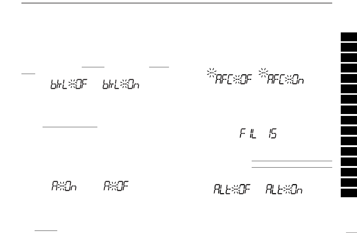
DDDisplay dimmer
Adjust the display lighting condition.
The levels 1 (dark) to 8 (bright: default) are available.
DDDisplay color
The display color can be set to amber (default), yellow or
green.
Yellow setting Green setting
41
9SET MODE
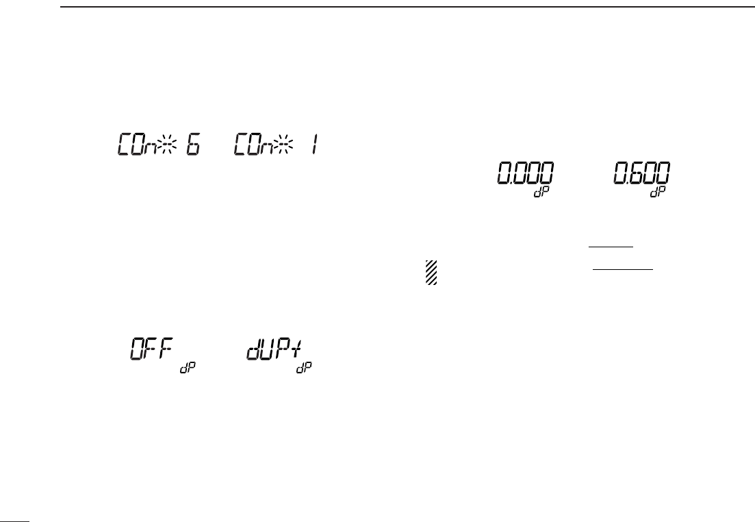
DDDisplay contrast
The LCD contrast can be adjusted through 9 levels.
(default: 5)
DDDuplex direction
Sets the duplex direction. The displaying frequency shifts the
programmed offset frequency (below) when monitor function
is in use (pushing [MONI•T/T-SCAN]).
•OFF : Simplex operation. (default)
•DUP– : The displaying frequency shifts down during
monitor.
•DUP+ : The displaying frequency shifts up during moni-
tor.
DDOffset frequency
Sets the duplex offset frequency for each frequency band in-
dependently within 0 to 1000 MHz range. During duplex op-
eration (DUP– or DUP+), the monitoring frequency (pushing
[MONI•T/T-SCAN]) shifts the set frequency.
The default value may differ according to the selected fre-
quency band (before accessing set mode)and receiver version.
The selected tuning step in VFO mode is used for setting
the offset frequency.
42
9
SET MODE
11
DDTone frequency
Sets subaudible tone frequency for tone squelch operation.
Total of 51 tone frequencies (67.0–254.1 Hz) are available.
(default: 88.5 Hz)
•Available tone frequency list
DDDTCS code
Sets DTCS code for DTCS squelch operation. Total of 104
codes (023–754) are available. (default: 023)
•Available DTCS code list
DDDTCS polarity
Sets DTCS polarities from n (normal) and r (reverse).
(default: n)
normal (default) reverse
023
025
026
031
032
036
043
047
051
053
125
131
132
134
143
145
152
155
156
162
245
246
251
252
255
261
263
265
266
271
356
364
365
371
411
412
413
423
431
432
506
516
523
526
532
546
565
606
612
624
054
065
071
072
073
074
114
115
116
122
165
172
174
205
212
223
225
226
243
244
274
306
311
315
325
331
332
343
346
351
445
446
452
454
455
462
464
465
466
503
627
631
632
654
662
664
703
712
723
731
732
734
743
754
67.0
69.3
71.0
71.9
74.4
77.0
79.7
82.5
85.4
88.5
91.5
94.8
097.4
100.0
103.5
107.2
110.9
114.8
118.8
123.0
127.3
131.8
136.5
141.3
146.2
151.4
156.7
159.8
162.2
165.5
167.9
171.3
173.8
177.3
179.9
183.5
186.2
189.9
192.8
196.6
199.5
203.5
206.5
210.7
218.1
225.7
229.1
233.6
241.8
250.3
254.1
43
9SET MODE
DDVSC setting
Turns VSC (Voice Squelch Control) function ON and OFF.
(default: OFF)
DDScan resume timer
Selects scan resume timer from SCT-15 (default), SCT-10,
SCT-5 and SCP-2. Scan resumes after the specified period
when the received signal disappears.
•SCT-15/10/5 : Scan pauses for 15/10/5 sec. when the
received signal disappears.
•SCP-2 : Scan pauses on a signal until signal dis-
appears, then resumes 2 sec. after the
signal disappears.
DDProgram scan skip setting
Sets the program scan skip setting ON and OFF for VFO
scan operation, such as programmed scan. (default: ON)
This item appears when set mode is accessed from VFO
mode only.
DDScan skip area setting
Sets the pre-programmed scan skip area setting ON and OFF
for VFO scan operation, such as programmed scan.
This item appears only when the scan skip area setting is pro-
grammed by the clone ((p. 44)) and set mode is accessed
from VFO mode.
DDMemory name setting
Sets memory name setting from ON (appear) and OFF (not
appear; default) for memory name appearance.
This item appears when set mode is accessed from memory
mode only.
44
9
SET MODE
1
2
3
4
5
6
7
8
9
10
11
12
13
14
15
16
DDMemory bank link function
Sets the memory bank link function ON and OFF (default).
The link function provides continuous banks scan, that scans
all contents in the selected banks during bank scan.
This item appears when set mode is accessed from memory
mode only.
•Bank link setting
qRotate [DIAL] to select the memory bank link function ON.
wPush and hold [SET•LOCK] or [S.MW•MW] for 1 sec. to
enter bank link setting mode.
ePush [SET•LOCK] or [S.MW•MW] to select the desired
bank to be linked.
•A: Bank A • b : Bank B • C : Bank C • d : Bank D
• E : Bank E • F : Bank F • G : Bank G • H : Bank H
• J : Bank J • k : Bank K • L : Bank L • m: Bank M
• n : Bank N • o : Bank O • P : Bank P • q : Bank Q
• r : Bank R • t : Bank T • U : Bank U • W: Bank W
• y : Bank Y
rRotate [DIAL] to select “On” to linking the bank.
tRepeat steps eand rto set the link condition.
yPush [TS•MODE] or any switch below the display to return
to set mode.
DDAFC setting
Turns AFC (Automatic Frequency Control) function ON and
OFF. (default: OFF)
DDFilter setting
Select the IF filter passband width from 3, 6, 15, 50 and 230
(depending on the selected mode.)
DDWeather alert function
Turns weather alert function ON and OFF.
U.S.A./CANADA versions only
Bank A ON Bank A OFF
45
9SET MODE
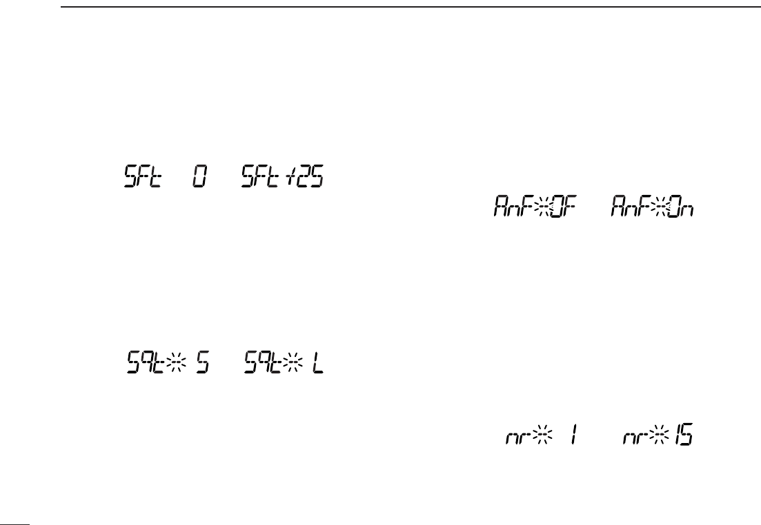
DDIF shift frequency setting
Select the IF shift frequency up to ±25 steps in 1 step (50 Hz
step).
This item appears when the receive mode is selected SSB or
CW mode.
DDSquelch delay
Selects squelch delay from short and long to prevent re-
peated opening and closing of the squelch during reception
of the same signal.
•S : Short squelch delay.
•L : Long squelch delay.
DDANF setting
Turns ANF (Automatic Notch Filter) function ON and OFF.
The ANF function automatically attenuates up to 3 beat tones,
tuning signals, etc. even if they are moving. The ANF func-
tion can be used in SSB, AM, FM and WFM modes.
☞This item appears when optional UT-106 is installed.
DDNR setting
Selects NR (Noise Reduction) level from 1 to 15 and OFF
(Default).
The NR function enhances desired signals in the presence of
noise by using the DSP circuit. The amount of enhancement
is adjustable.
The NR level can result in audio signal masking. Set the
noise reduction level for maximum readability.
☞This item appears when optional UT-106 is installed.
Center position (default) Highest

46
10
OTHER FUNCTION
1
2
3
4
5
6
7
8
9
10
11
12
13
14
15
16
49
10 OTHER FUNCTIONS
■Partial reset
If you want to initialize the operating conditions (VFO fre-
quency, VFO settings, set mode contents) without clearing
the memory contents, a partial resetting function is available
for the receiver left and right bands independently.
➥While pushing desired band’s [VFO/MR•S.MW], turn the
power ON to partially reset the desired band (left or right).
✔
Hint!
When pushing both [VFO/MR•S.MW] and turning the power
ON, partially reset both bands at the same time.
■ALL reset
The function display may occasionally display erroneous in-
formation (e.g. when first applying power). This may be
caused externally by static electricity or by other factors.
If this problem occurs, turn power OFF. After waiting a few
seconds, turn power ON again. If the problem persists, per-
form the following procedure.
•Partial resetting is also available. See left for details.
IMPORTANT!:
Resetting the receiver CLEARS all memory information
and initializes all values in the receiver.
➥While pushing both band’s [MHz•TS], turn the power ON
to reset the CPU.
[MHz•TS]
While pushing both [MHz•TS], turn power ON.
[MHz•TS]
AT
POWER ON
Left band partial reset.
Right band partial reset.
AT
POWER ON

1-1-32 Kamiminami, Hirano-ku, Osaka 547-0003, Japan