ICOM orporated 287901 Communication Receiver User Manual
ICOM Incorporated Communication Receiver
UserManual.wiki
>
ICOM orporated
>
287901 User Manual
User Manual
Navigation menu
Upload a User Manual
Namespaces
Wiki Guide
HTML
PDF
Info
Views
User Manual
Discussion / Help
Navigation
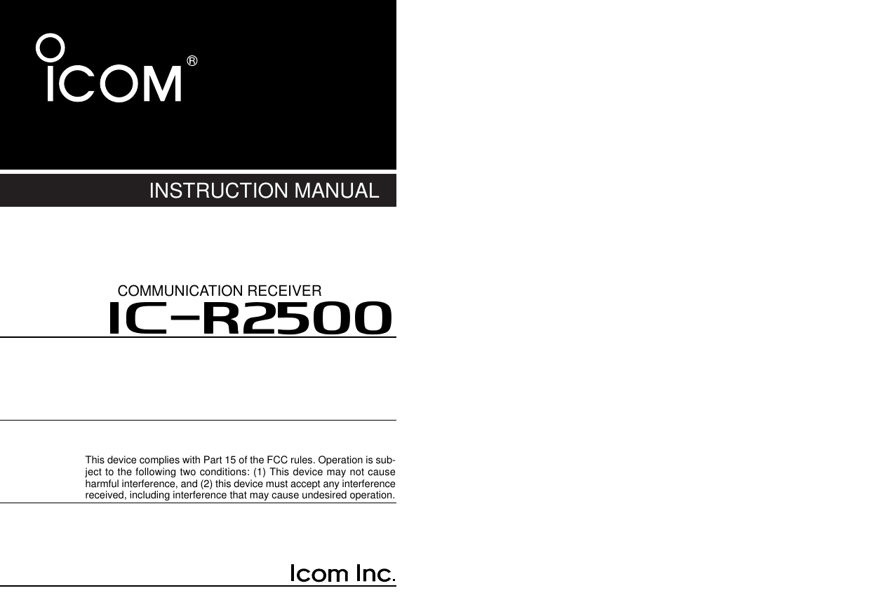
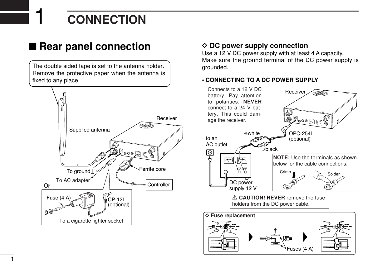
![21CONNECTION2DDOPC-1156 connectionqConnect the controller plug to the OPC-1156 joint.wDetach the ferrite core from the controller cable, then at-tach it to the OPC-1156 as shown below.• Make sure to roll the cable to the ferrite core.eConnect the OPC-1156 plug to the [CONTROLLER] con-nector of the receiver.■Antennal installationDAntenna locationTo obtain maximum performance from the receiver, select ahigh-quality antenna and mount it in a good location. A non-radial antenna should be used when using a magnetic mount.ReceiverControllerJointFerrite core](https://usermanual.wiki/ICOM-orporated/287901/User-Guide-804038-Page-7.png)
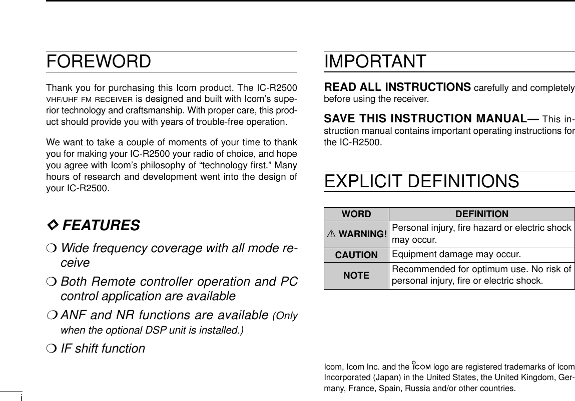
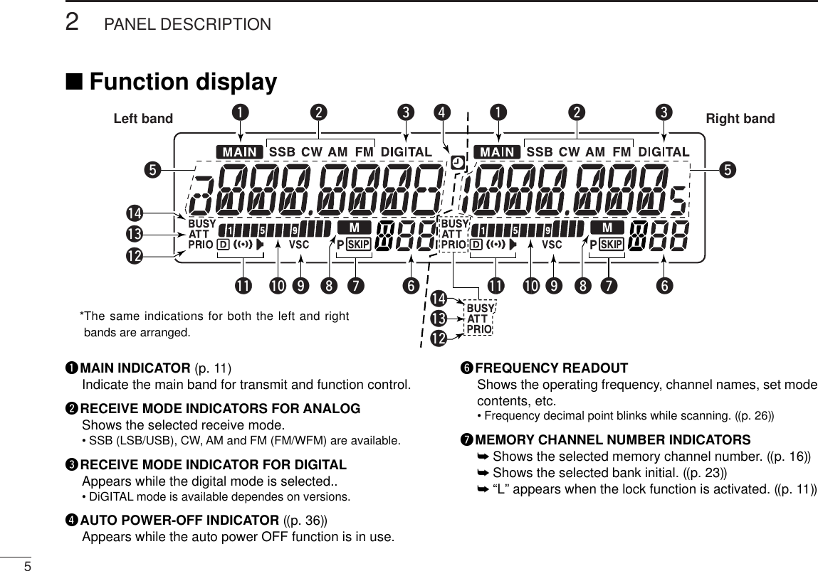
![3PANEL DISCRIPTION2■Front panel— controllerqPOWER KEY [PWR•]➥Turns the controller power ON and OFF when pushedand held for 1 sec.➥Continue to hold this key down for 2 sec. after powerON to turn the lock function ON and OFF. (p. 15)wSET•SKIP KEY [SET•SKIP]➥Enters set mode when pushed. (p. 56)➥Push and hold for 1 sec. to turn the channel skip settingON and OFF for memory/VFO skip scan operation.(p. ??)eMONITOR•TONE•TONE SCAN SWITCH[MONI•T/T-SCAN]➥Push to turn the monitor function ON and OFF. (p. ??)➥Push and hold for 1 sec. to enter the tone function se-lection mode. (pgs. ??, ??)•Subaudible tone encoder, pocket beep (CTCSS), tonesquelch, pocket beep (DTCS), DTCS squelch or tone func-tion OFF can be selected.➥Push and hold for 1 sec. during tone function selectionmode to start the tone scan. (p. ??)rMODE•SCAN SWITCH [MODE•SCAN]➥Push and hold for 1 sec. to enter the mode selectioncondition. (p. ??)•Rotate [DIAL] to select the desired operating mode..➥Starts scan when pushed and held for 1 sec. (p. ??)•Cancels a scan when pushed during scan.tATTENUATOR/PRIORITY SWITCH [ATT•PRIO]➥Push to turn the ATT (Attenuator) function ON and OFF.MAINAGCS.MWTSVFO/MRMHzMAINNBS.MWVFO/MRTSMHzVOLVOLDIALDIALSQLSQLMONIT/T-SCANMODESCAN ATTPRIOCOMMUNICATIONS RECEIVERiR2500PWR SETSKIPFunction display (pgs. 3, 4)qwert*The keys wto tare forthe MAIN band only.](https://usermanual.wiki/ICOM-orporated/287901/User-Guide-804038-Page-8.png)
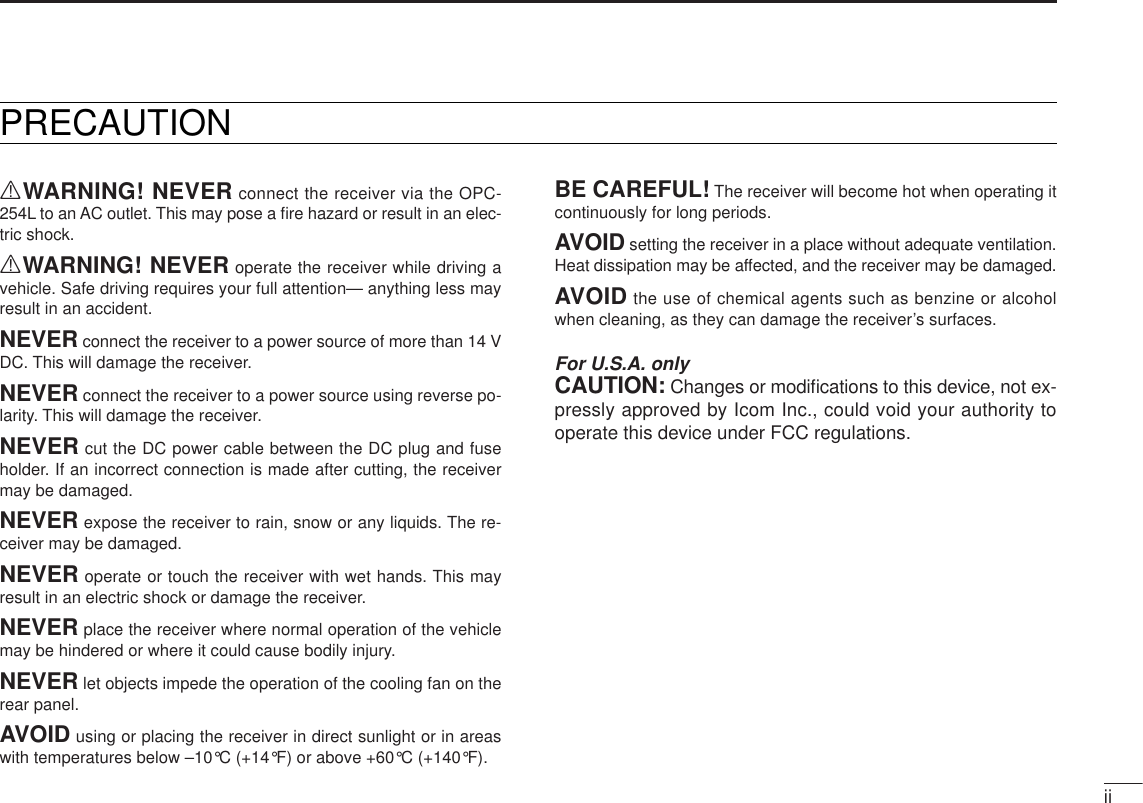
![42PANEL DESCRIPTION12345678910111213141516(p. ??)➥Starts priority watch when pushed for 1 sec. (p. ??)ya MAIN•AGC KEY [MAIN•AGC]➥Push to select the main band. (p. 11)➥Push for 1 sec. to turn the AGC (Automatic Gain Con-trol) function ON and OFF. (p. ??)yb MAIN•NB KEY [MAIN•NB]➥Push to select the main band. (p. 11)➥Push for 1 sec. to turn the NB (Noise Blanker) functionON and OFF. (p. ??)uVFO/MEMORY•MEMORY WRITE KEY [VFO/MR•S.MW]➥Push to select and toggle VFO, memory and weatherchannel* modes. (pgs. 12, 29, 38, 65)*Weather channels available for USA versions only.➥Selects a memory channel for programming whenpushed for 1 sec. (pgs. 30, 39, 42)iMHz TUNING•TUNING STEP [MHz•TS]➥Selects band selection, 1 MHz or 10 MHz tuning whenpushed. ((p. 9))➥Push and hold for 1 sec. to enter the tuning step selec-tion mode. (p. ??)•Rotate [DIAL] to select the desired tuning step.oVOLUME CONTROL [VOL] (p. 16)Adjusts the audio level for relative band.!0TUNING DIAL [DIAL]Selects the operating frequency (p. 13), memory channel(p. 29), the setting of the set mode item and the scanningdirection (p. 41) for the relative band.!1SQUELCH CONTROL [SQL]Varies the squelch level for relative band. (p. 16)MAINAGCS.MWTSVFO/MRMHzMAINNBS.MWVFO/MRTSMHzVOLVOLDIALDIALSQLSQLMONIT/T-SCANMODESCAN ATTPRIOCOMMUNICATIONS RECEIVERiR2500PWR SETSKIPLeft band Right bandooybui!0yaui!0!1!1*The same controls for both the left andright bands are arranged in symmetry.](https://usermanual.wiki/ICOM-orporated/287901/User-Guide-804038-Page-9.png)
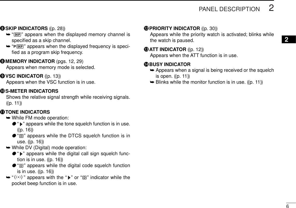
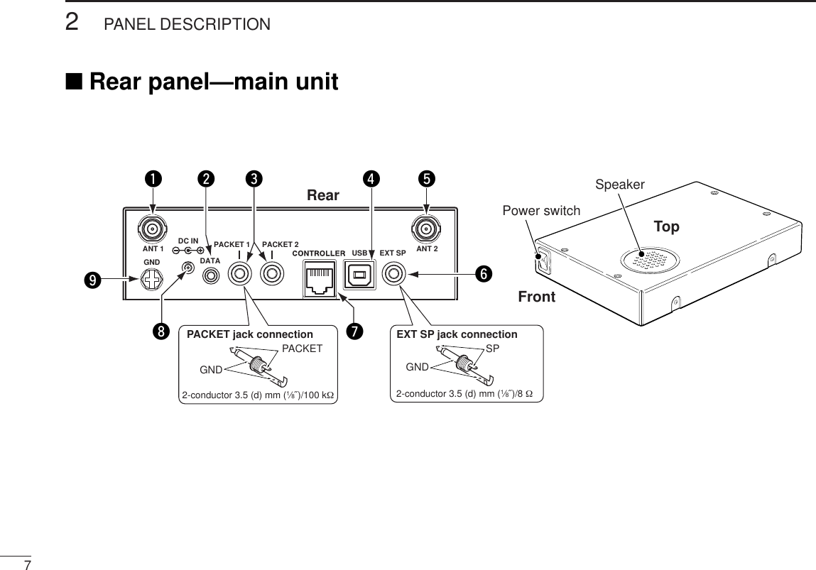
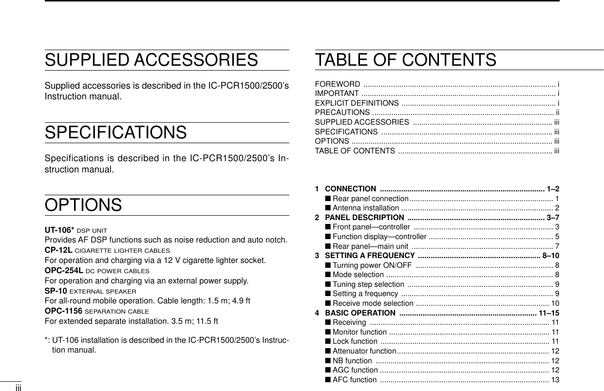
![82PANEL DESCRIPTION2qANTENNA CONNECTOR1 [ANT1]Connects a 50 Ωantenna with a BNC connector and a 50Ωcoaxial cable.wDATA JACK [DATA]Connect to a PC or GPS receiver via the RS-232 cable (D-sub 9 pin) for data communication in the RS-232 format.ePACKET JACKS [PACKET1/2]Connect a TNC (Terminal Node Controller), etc. for datacommunications. The receiver can receive 9600 bpspacket communication (AFSK).rUSB CONNECTOR [USB]Connects to a PC via the supplied USB cable.tANTENNA CONNECTOR2 [ANT2]Connects a 50 Ωantenna with a BNC connector and a 50Ωcoaxial cable.yEXTERNAL SPEAKER JACK [EXT SP]Connects an 8 Ωexternal speaker.•Audio output power is more than 0.5 W.uCONTROLLER [CONTROLLER]Connects to a controller via an extension cable.iPOWER JACK [DC IN]Accepts 12 V DC ±15% with the supplied DC power cable.oGROUND TERMINAL [GND]Connect this terminal to a ground.Pin 2 (RxD), Pin 3 (TxD), Pin 5 (GND)to [DATA] jackTxD2.5(d) mm Less than10(d) mmGNDRxD1569RS-232(DB-9 female)](https://usermanual.wiki/ICOM-orporated/287901/User-Guide-804038-Page-13.png)
![9SETTING A FREQUENCY3■PreparationDTurning power ON/OFF➥Push [PWR•]for 1 sec. to turn power ON and OFF.DMAIN bandThe IC-R2500 can receive 144 MHz and 430(440) MHz bandsignals simultaneously. ➥Push the desired band’s [MAIN•AGC] to select the mainband.•“Q” indicates the main band.DVFO and memory modesThe receiver has 2 basic operating modes: VFO mode andmemory mode. Select VFO mode first to set an operating fre-quency.➥Push the desired band’s [VFO/MR•S.MW] to select VFOmode.➥Push [VFO/MR•S.MW] again to select memory mode.•“!” indicator appears when memory mode is selected.! indicator appears whenmemory mode is selected[VFO/MR¥S.MW] Push the desired band’s [MAIN]Push [PWR] for 1 sec.](https://usermanual.wiki/ICOM-orporated/287901/User-Guide-804038-Page-14.png)
![■Tuning step selectionWhen using the tuning dial to change the frequency, or whena scan function is activated, the frequency changes in incre-ments determined by the set tuning step. This can bechanged if desired.The following tuning step are available.• 0.01 kHz (10 Hz) • 0.02 kHz (20 Hz) • 0.05 kHz (50 Hz)• 0.1 kHz (100 Hz) • 0.5 kHz (500 Hz) • 1 kHz• 2.5 kHz • 5 kHz • 6.25 kHz• 8.33 kHz • 9 kHz • 10 kHz• 12.5 kHz • 15 kHz • 20 kHz• 25 kHz • 30 kHz • 50 kHz• 100 kHz • 125 kHz • 150 kHz• 200 kHz • 500 kHz • 1000 kHz (1 MHz)qPush the desired band’s [MAIN] to select the main band.•Push the same band’s [VFO/MR•S.MW] to select VFO mode, ifnecessary.wPush and hold [MHz•TS] for 1 sec. to enter tuning step se-lect mode.eRotate the same band’s [DIAL] to select the desired tun-ing step.rPush [MHz•TS] to exit set mode.•Or push the same band’s any other keys or common keys (belowthe dusplay) to exit tuning step select mode.[DIAL] [MHz•TS] 103SETTING A FREQUENCY3](https://usermanual.wiki/ICOM-orporated/287901/User-Guide-804038-Page-15.png)
![113SETTING A FREQUENCY■Using the tuning dialqRotate the desired band’s [DIAL] to set the frequency.•If VFO mode is not selected, push the same band’s[VFO/MR•S.MW] to select VFO mode.•The frequency changes in the selected tuning steps. (p. 14)wTo change the frequency band or in 1 MHz (10 MHz) steps,push [MHz•TS], then rotate the band’s [DIAL].ePush [MHz•TS] to exit tuning step select mode.■Receive mode selectionReceive modes are determined by the physical properties ofthe radio signals. The receiver has 7 receive modes: LSBUSB, CW, AM, WFM, FM and digital modes. The mode se-lection is stored independently in each memory channels.Typically, AM mode is used for the AM broadcast stations(0.495–1.620 MHz) and air band (118–135.995 MHz), andWFM is used for FM broadcast stations (76–107.9 MHz).qPush [MODE•SCAN] to enter receive mode select mode.wRotate [DIAL] to select the desired mode.ePush any switch to exit receive mode select mode.[DIAL] [MODE•SCAN]While the band selection mode is selected, the digits below 100 kHz disappear.While 1 MHz tuning step is selected, the 1 MHz digit blinks.While 10 MHz tuning step is selected, the 10 MHz digit blinks.Push [VFO/MR•S.MW]Rotate [DIAL]](https://usermanual.wiki/ICOM-orporated/287901/User-Guide-804038-Page-16.png)
![124BASIC OPERATION12345678910111213141516■ReceivingqSet the audio level for the main band.➥Push the desired band’s [MAIN].➥Push [MONI•T/T-SCAN] to open the squelch.➥Rotate the main band’s [VOL] to adjust the audio level.➥Push [MONI•T/T-SCAN] to close the squelch.wSet the squelch level.➥Rotate the main band’s [SQL] fully counterclockwise inadvance, then rotate [SQL] clockwise until the noisejust disappears.eSet the operating frequency in the main band. (pgs. 11–13)•When interference is received, push [ATT•PRIO] to turn the at-tenuator function ON. (p. 17)rWhen receiving a signal on the set frequency, squelchopens and the receiver emits audio.•“BUSY” appears and the S-meter shows the relative signalstrength for the received signal.■Monitor functionThis function is used to listen to weak signals without disturb-ing the squelch setting or to open the squelch manually evenwhen mute functions such as the tone squelch are in use. ➥Push [MONI•T/T-SCAN] for 1 sec. to open the squelch.•Push [MAIN] to select the desired band (left or right) as the mainband in advance.•“BUSY” blinks.•Push [MONI•T/T-SCAN] again to cancel the function.[MONI•T/T-SCAN]Appears when receiving a signal.](https://usermanual.wiki/ICOM-orporated/287901/User-Guide-804038-Page-17.png)
![■Lock functionsTo prevent accidental frequency changes and unnecessaryfunction access, use the lock function.➥Continue to hold [SET• ] down for 2 sec. after powerON to turn the lock function ON and OFF.•[MONI•T/T-SCAN] (monitor function only), [VOL], [SQL],[MAIN•AGC] (main band selection only) and [MAIN•NB] (mainband selection only) can be used while the channel lock functionis in use.■Attenuator functionThe attenuator prevents a desired signal from distorting whenvery strong signals are near the desired frequency or whenvery strong electric fields, such as from a broadcasting sta-tion, are near your location. The attenuator gain is about 20dB and this function can be activated on 1300 MHz or below.➥Push [ATT•PRIO] momentarily to toggle the attenuatorfunction ON and OFF.•“ATT” appears when the attenuator function is in use.[ATT•PRIO]Appears[PWR• ]2 “L”s appear while the lock function is activated.134BASIC OPERATION](https://usermanual.wiki/ICOM-orporated/287901/User-Guide-804038-Page-18.png)
![144BASIC OPERATION12345678910111213141516■NB functionThe NB (noise blanker) function removes pulse-type noisewhen SSB, CW or AM mode is selected.➥Push and hold [MAIN•NB] for 1 sec. to toggle the NB func-tion ON and OFF.•“nb-On” or “nb-OF” appears for a moment when the NB functionis turned ON or OFF, respectively.■AGC functionThe AGC (Automatic Gain Control) function controls receivergain to produce a constant audio output level even when thereceived signal strength is varied by fading, etc. This AGCslow function is selectable for SSB, CW or AM mode.➥Push and hold [MAIN•AGC] for 1 sec. to toggle the AGCfunction Slow and Fast.•“AGC-S” or “AGC-F” appears for a moment when the AGC func-tion is selected Slow or Fast, respectively.While in FM or WFM mode, the AGC function is fixed asFast and AGC Slow cannot be selected.[MAIN•AGC][MAIN•NB]](https://usermanual.wiki/ICOM-orporated/287901/User-Guide-804038-Page-19.png)
![154BASIC OPERATION■AFC function [The AFC (Automatic Frequency Control) function tunes thedisplayed frequency automatically when an off-center fre-quency is received. It activates in FM mode and only whenthe selected IF filter is 6 kHz or 15 kHz.qSelect FM mode.wPush [SET•SKIP] to enter set mode.ePush [SET•SKIP] or [ATT•PRIO] several times until “AFC”appears.rRotate [DIAL] to toggle the AFC function ON and OFF.tPush any switch for main band to exit set mode.■VSC function [The VSC (Voice Squelch Control) function opens the squelchonly when receiving a modulated signal. This function is veryuseful while scanning, the VSC pauses only when modulatedsignals are received. Scanning continues when unmodulatedor beat signals are received.qPush [SET•SKIP] to enter set mode.wPush [SET•SKIP] or [ATT•PRIO] several times until “VSC”appears.eRotate [DIAL] to toggle the VSC function ON and OFF.rPush any switch for main band to exit set mode.[SET•SKIP][DIAL] [ATT•PRIO][SET•SKIP][DIAL] [ATT•PRIO]](https://usermanual.wiki/ICOM-orporated/287901/User-Guide-804038-Page-20.png)
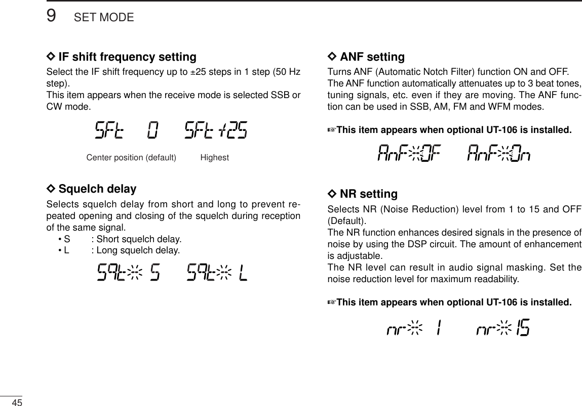
![164BASIC OPERATION12345678910111213141516■IF filter selection [The receiver has 2 to 4 passband width IF filters for eachmode. Selectable passband width are from 3, 6, 15, 50 and230 (depending on the selected mode).• Selectable passband width for each mode.SSB mode : 3 (2.8 kHz) or 6 kHzCW mode : 3 (2.8 kHz) or 6 kHzAM mode : 3 (2.8 kHz), 6 kHz, 15 kHz or 50 kHzWFM mode: 50 kHz or 230 kHzFM mode : 6 kHz, 15 kHz or 50 kHzqPush [SET•SKIP] to enter set mode.wPush [SET•SKIP] or [ATT•PRIO] several times until “VSC”appears.eRotate [DIAL] to select the desired IF passband width.rPush any switch for main band to exit set mode.■IF shift function [The IF shift function electronically changes the passband fre-quency of the IF (Intermediate frequency) and cuts out higheror lower frequency components of the IF to reject interfer-ence. This function is available when the receive mode is se-lected SSB or CW mode, and shifts the IF frequency up to±25 steps in 1 step (50 Hz).qPush [SET•SKIP] to enter set mode.wPush [SET•SKIP] or [ATT•PRIO] several times until “SFt”appears.eRotate [DIAL] to set the shifting direction and frequencyrange.rPush any switch for main band to exit set mode.Center position(default)HighestLowest[SET•SKIP][DIAL] [ATT•PRIO][SET•SKIP][DIAL] [ATT•PRIO]](https://usermanual.wiki/ICOM-orporated/287901/User-Guide-804038-Page-21.png)
![174BASIC OPERATIONDuplex communication uses two different frequencies fortransmitting and receiving. Generally, duplex is used in com-munication through a repeater, some utility communications,etc.During duplex operation, the transmit station frequency isshifted from the receive station frequency by the offset fre-quency. Repeater information (offset frequency and shift di-rection) can be programmed into memory channels. ((p. 16))DDSetting [qPush [SET•SKIP] to enter set mode.wPush [SET•SKIP] or [ATT•PRIO] several times until theduplex direction setting item “OFF dP,” “DUP– dP” or “DUP+dP” appears.eRotate [DIAL] to select the duplex direction, “DUP– dP” or“DUP+ dP.”rPush [SET•SKIP] once to select the offset frequency set-ting item.tRotate [DIAL] to set the desired offset frequency within0.000–1000.000 MHz range.•The tuning step, selected in VFO mode, is used for setting.•Push [MHz• TS] then rotate [DIAL] to change the frequency in10 MHz steps, or push again then rotate [DIAL] to change thefrequency in 1 MHz steps. (Each push toggles 1MHz, 10 MHzor selected tuning steps.)yPush any switch for main band to exit set mode.[SET•SKIP][DIAL] [ATT•PRIO]■Duplex operation](https://usermanual.wiki/ICOM-orporated/287901/User-Guide-804038-Page-22.png)
![184BASIC OPERATION12345678910111213141516DDOperationqSet the receive station frequency (repeater output frequency).wPush [MONI•T/T-SCAN] to monitor the transmit station fre-quency (repeater input frequency) directly.[MONI¥T/T-SCAN]Frequency shifts the offset frequency](https://usermanual.wiki/ICOM-orporated/287901/User-Guide-804038-Page-23.png)
![19MEMORY OPERATION5■General descriptionThe receiver has 1100 memory channels including 100 scanedge memory channels (50 pairs) for storage of often-usedfrequencies. And a total of 21 memory banks, A to H, J to R,T, U, W and Y are available for storing groups of frequencies,etc. Up to 100 channels can be assigned into a bank.DDMemory channel contentsThe following information can be programmed into memorychannels:•Operating frequency ((p. 9))•Receive mode ((p. 10))•Duplex direction (DUP+ or DUP–) with an offset fre-quency ((p. 15))•Tone squelch or DTCS squelch ON/OFF ((p. 33))•Tone squelch frequency or DTCS code with polarity((p. 38))•Scan skip information ((p. 28))■Memory channel selectionqPush the desired band’s [VFO/MR•S.MW] once or twiceto select memory mode.•“M” indicator appears.wRotate the same band’s [DIAL] to select the desired mem-ory channel.•Programmed memory channels only can be selected.! indicator appears whenmemory mode is selected[VFO/MR¥S.MW] If memory banks or weather channels* mode appears whenpushed [VFO/MR•S.MW] at step q, push [MHz•TS] and ro-tate [DIAL] to select “bAnk --,” then push any switches formain band or common switches to exit from settings.*Available for USA/CANADA versions only.](https://usermanual.wiki/ICOM-orporated/287901/User-Guide-804038-Page-24.png)
![205MEMORY OPERATION5■Programming a memory channel[EXAMPLE]: Programming 145.800 MHz into memory channel 20 (blank channel).Push Rotate for setting frequency, etc. Push for 1 sec.Rotate Push for 1 sec. and continue to push ➠Beep“BeepBeepBeep“““““BeepBeep““S.MWVFO/MRS.MWVFO/MRS.MWVFO/MRRelease S.MWVFO/MRVFO settings, including the set mode contents such as sub-audible tone frequency, offset, scan skip information can beprogrammed into a memory channel.qSet the desired frequency in the desired band (left or right). ➥Push the desired band’s [VFO/MR•S.MW] once or twiceto select VFO mode.➥Set the frequency using the same band’s [DIAL].➥Set other data (e.g. tone frequency, duplex information,etc.) if required.wPush and hold the same band’s [VFO/MR•S.MW] for1sec. to enter select memory write mode.•“!” indicator and the memory channel number blink.eRotate [DIAL] to select the memory channel to be pro-grammed.•Memory channels not yet programmed are blank.rPush and hold [VFO/MR•S.MW] for 1 sec. to program.•3 beeps sound•Memory channel number automatically increases when contin-uing to push [VFO/MR•S.MW] after programming.✔CONVENIENTMemory programming can be performed in versatile wayse.g. memory channel to the same (or different) memory chan-nel, etc.](https://usermanual.wiki/ICOM-orporated/287901/User-Guide-804038-Page-25.png)
![215MEMORY OPERATION[EXAMPLE]: Programming “CLUB” into memory channel 12.Select memory channel Push for 1 sec.Rotate Push for 1 sec.BeepBeepBeep“““““S.MWVFO/MRS.MWVFO/MRS.MWVFO/MR Push twiceSETSKIPRepeat theprevioussteps.Each memory channel can be programmed with an alphanu-meric channel name for easy recognition and can be indicatedindependently by channel. Names can be a maximum of 6characters— see the table on next page for available charac-ters.qSelect the desired memory channel to be programmed.➥Push [VFO/MR•S.MW] to select memory mode, then ro-tate [DIAL] to select the desired memory channel.wPush and hold [VFO/MR•S.MW] for 1 sec. to enter selectmemory write mode.•“!” indicator and the memory channel number blink.ePush [SET•SKIP] several times to select the memoryname programming condition, “m nAmE.”•Frequency readouts disappear and a cursor blinks.rRotate [DIAL] to select the desired character.•The selected character blinks.tPush [ATT•PRIO] to move the cursor to the right.•Repeat pushing [ATT•PRIO] to return to the first digit.yRepeat steps rand tuntil the desired channel namesare displayed.uPush and hold [VFO/MR•S.MW] for 1 sec. to program thename and exit select memory write mode.■Programming channel names](https://usermanual.wiki/ICOM-orporated/287901/User-Guide-804038-Page-26.png)
![225MEMORY OPERATION12345678910111213141516• Available characters DDTo indicate the channel name [The channel name indication can be set for independentmemory channels.qSelect the desired memory channel in the main band.➥Push [VFO/MR•S.MW] once or twice to select memorymode, then rotate [DIAL] to select the desired memorychannel.•“!” and memory channel number appear.wPush [SET•SKIP] to enter set mode.ePush [SET•SKIP] or [ATT•PRIO] several times to select“Anm” item.rRotate [DIAL] to turn the memory name indication ON.tPush any switch for main band to exit set mode.NOTE: When no memory name is programmed, the storedfrequency is displayed.(1)(B)(L)(V)(+)(2)(C)(M)(W)(–)(3)(D)(N)(X)(/)(4)(E)(O)(Y)(=)(5)(F)(P)(Z)(6)(G)(Q)(space)(7)(H)(R)(8)(I)(S)(9)(J)(T)(0)(A)(K)(U)](https://usermanual.wiki/ICOM-orporated/287901/User-Guide-804038-Page-27.png)
![235MEMORY OPERATION[EXAMPLE]: Transferring memory channel 30 contents to VFO.Push to select memory mode.Rotate for selecting memory channel. Push for 3 sec.S.MWVFO/MRS.MWVFO/MRThis function transfers a memory channel’s contents to VFO(or another memory channel). This is useful when searchingfor signals around a memory channel frequency and for re-calling the subaudible tone frequency etc.DMemory➪VFOqSelect the desired band’s (left or right) memory channel tobe transferred.➥Push the desired band’s [VFO/MR•S.MW] several timesto select memory mode, then rotate the same band’s[DIAL] to select the desired memory channel.•“!” and memory channel number appear.wPush and hold [VFO/MR•S.MW] for 3 sec. to transfer theselected memory channel contents to VFO mode.•VFO mode is selected automatically.■Copying memory contents](https://usermanual.wiki/ICOM-orporated/287901/User-Guide-804038-Page-28.png)
![245MEMORY OPERATION5DMemory➪memoryqSelect the desired band’s (left or right) memory channel tobe transferred.➥Push the desired band’s [VFO/MR•S.MW] several timesto select memory mode, then rotate the same band’s[DIAL] to select the desired memory channel.•“!” and memory channel number appear.wPush and hold the same band’s [VFO/MR•S.MW] for 1sec. to enter select memory write mode.•“!” and memory channel number blink.eRotate [DIAL] to select the target memory channel.•Scan edge channels, 0A/0B to 49A/49B can also be selected.rPush and hold [VFO/MR•S.MW] for 1 sec. to transfer theselected memory channel contents to the target memory.•The targeted memory and transferred contents are indicated.[EXAMPLE]: Transferring memory channel 22 contents to channel 23.Push to select memory mode.Select the target channel.Rotate for selecting memory channel.Push for 1 sec.S.MWVFO/MRS.MWVFO/MRPush for 1 sec.S.MWVFO/MR](https://usermanual.wiki/ICOM-orporated/287901/User-Guide-804038-Page-29.png)
![5MEMORY OPERATION25Contents of programmed memories can be cleared (blanked),if desired.qPush [VFO/MR•S.MW] to select VFO mode in the mainband.wPush the same band’s [VFO/MR•S.MW] for 1 sec. to enterselect memory write mode.•“!” indicator and the memory channel number blink.eRotate the same band’s [DIAL] to select the memorychannel to be cleared.•Memory channels not yet programmed are blank.rPush [SET•SKIP] three times to select “CLEAR,” thenpush and hold [VFO/MR•S.MW] for 1 sec.•3 beeps sound.•The cleared channel changes to blank channel•“!” and the memory channel number blink continuously.tPush the same band’s [MAIN] or [MHz•TS] to exit selectmemory write mode, or repeat steps eand rto clearother channel.yPush the same band’s [VFO/MR•S.MW] to return to VFOmode.☞NOTE: Be careful!— the contents of cleared memoriesCANNOT be recalled.[EXAMPLE]: Clearing memory channel 20.Push to select VFO. Rotate for selecting memory channel.Push for 1 sec.S.MWVFO/MR S.MWVFO/MRS.MWVFO/MRPush any switch for main band other than , then push to return to VFO.S.MWVFO/MR S.MWVFO/MRPush three times, then push for 1 sec.SETSKIPBeepBeepBeep“““““■Memory clearing](https://usermanual.wiki/ICOM-orporated/287901/User-Guide-804038-Page-30.png)
![5MEMORY OPERATION265■Memory bank setting [The IC-R2500 has a total of 21 banks (A to H, J to R, T, U,W, Y). Regular memory channels, 0 to 999, may assignedinto the desired bank for easy memory management.qSelect the desired memory channel.➥Push [VFO/MR•S.MW] to select memory mode in themain band, then rotate the same band’s [DIAL] to se-lect the desired memory channel.•“!” and memory channel number appear.wPush and hold the same band’s [VFO/MR•S.MW] for 1sec. to enter select memory write mode.•“!” indicator and the memory channel number blink.ePush [SET•SKIP] once to select “bAnk.”rRotate [DIAL] to select the desired bank and bank chan-nel.•Push [ATT•PRIO] to toggle the bank or bank channel selection.•Banks A to H, J to R, T, U, W and Y are available.•Vacant bank channel numbers are only be displayed.tPush and hold [VFO/MR•S.MW] for 1 sec. to program thebank and exit select memory write mode. Bank selection Bank channel selectionAfter [SET•SKIP]released[SET•SKIP][DIAL] [ATT•PRIO][VFO/MR•S.MW]](https://usermanual.wiki/ICOM-orporated/287901/User-Guide-804038-Page-31.png)
![275MEMORY OPERATION■Memory bank selectionqPush [VFO/MR•S.MW] to select memory mode in the de-sired band (left or right).wPush [MHz•TS] to enter memory type selection mode.eRotate [DIAL] to select the desired bank (A to H, J to R, T,U, W or Y).•Only programmed banks are displayed.rPush any switch for main band or common switch to setthe bank indication.•Bank’s indicator appears at top of the memory channel.tRotate [DIAL] to select the contents in the bank.yTo return to regular memory mode, repeat steps w–randselect “bAnk --” at step e.• Memory bank indication■Transferring bank contentsThe bank contents of programmed memory channels can becleared or transferred to another bank.INFORMATION: Even if the memory bank contents arecleared, the memory channel contents still remain pro-grammed.qSelect the desired bank contents to be transferred orerased from the bank in the main band.➥Push the main band’s [VFO/MR•S.MW] several timesto select memory mode.➥Push the same band’s [MHz•TS] then rotate the sameband’s [DIAL] to select the desired memory bank.•Bank’s indicator appears at top of the memory channel.➥Push any switch for main band or common switch to se-lect the bank then rotate [DIAL] to select the desiredcontents.[DIAL] [MHz•TS][VFO/MR•S.MW] Bank indicator appears[DIAL] [MHz•TS][VFO/MR•S.MW]](https://usermanual.wiki/ICOM-orporated/287901/User-Guide-804038-Page-32.png)
![285MEMORY OPERATION5wPush [VFO/MR•S.MW] for 1 sec. to enter select memorywrite mode.•“!” indicator and the memory channel number blink.ePush [SET•SKIP] once to select “bAnk.”rRotate [DIAL] to select the desired bank indicator to trans-fer or erase.•Push [ATT•PRIO] to toggle the bank or bank channel selection.•Select “– –” indication when erasing the contents from the bank.•Vacant bank channel numbers are only be displayed.tPush and hold [VFO/MR•S.MW] for 1 sec. to program thebank and return to regular memory mode. yRepeat steps qto tfor transferring or erasing an an-other banks contents.Bank selection Bank channel selectionAfter [SET•SKIP]releasedMemory channel blinks](https://usermanual.wiki/ICOM-orporated/287901/User-Guide-804038-Page-33.png)
![29SCAN OPERATION6■Scan typesScanning searches for signals automatically and makes iteasier to locate new stations for contact or listening purposes. There are 5 scan types and 4 resume conditions to suit youroperating needs.FULL SCAN ((p. 26)) Repeatedly scans all frequen-cies over the entire band.Some frequency ranges arenot scanned according to thefrequency coverage of the re-ceiver’s version.10kHz 3299.9999MHzScanJumpALL/SELECTED BANKSCAN ((p. 26))Repeatedly scans all bankchannels or selected bankchannels. The skip scan isalso available.SKIPSKIPA99 A03A00 A01 A02A04A98A05PROGRAMMED SCAN((p. 26))Repeatedly scans betweentwo user-programmed fre-quencies. Used for checkingfor frequencies within a speci-fied range such as repeateroutput frequencies, etc.Bandedge xxA xxBBandedgeScan edgesScanJumpMEMORY (SKIP) SCAN((p. 26))Repeatedly scans memorychannels except those set asskip channel. Skip channelscan be turned ON and OFFby pushing and holding[SET•SKIP] in memory mode.SKIPSKIPM 0 M 4M 1 M 2 M 3M 5M 199M 6FREQUENCY/MEMORYSKIP FUNCTION ((p. 28))Skips unwanted frequenciesor channels that inconve-niently stop scanning. Thisfunction can be turned ONand OFF by pushing andholding [SET•SKIP] in mem-ory mode.Bandedge BandedgeScanSKIP SKIPJump](https://usermanual.wiki/ICOM-orporated/287901/User-Guide-804038-Page-34.png)
![306SCAN OPERATION12345678910111213141516■Scan start/stopDPreparationScan resume condition ((p. 29)); program the scan edges((p. 27)); program two or more memory channels ((p. 17)); setskip settings ((p. 28)), if desired.DOperationqPush [VFO/MR•S.MW] once or twice to select VFO modefor full/programmed scan; or to select memory mode formemory/bank scan.•Select the desired bank in memory type selection mode for bankscan.wSet the squelch level to the point where noise is just muted.ePush and hold [MODE•SCAN] for 1 sec. to start the scan.•To change the scanning direction, rotate [DIAL].•The memory channel readout blinks the scan type as below.rPush [SET•SKIP] (or [ATT•PRIO]) to switch full and pro-grammed scan (P00 to P49), if VFO is selected in step q.tTo stop the scan, push [MODE•SCAN].About the scanning steps: The selected tuning step ineach frequency band (in VFO mode) is used during scan.The bank-link setting can be changed in set mode. See((p. 40)) for details.• During full scan • During programmed scan • During memory scan • During bank scanIndicates scan edge channels.• P01 stands for 01A/01B• P00 to P49 are available when they are programmed, and switches with [SET•SKIP].Indicates bank channel.Push [SET•SKIP] to se-lect full (ALL) or program-med scan (P00–P49) in sequence.While pushing and holding [MODE•SCAN], rotate [DIAL] also to select full (ALL) or programmed scan (P00–P49).NOTE: When SSB, CW, AM, FM, WFM or Digital mode frequencies are programmed into memory channels disorderly, memory scan takes a lot of time (very slow). Because changing modes takes a time. In this case, assign the SSB, CW, AM, FM, WFM or Digital mode frequencies into the separate bank respectively. And using the bank scan is helpful.IMPORTANT!: To perform memory or bank scan, two ormore memory/bank channels MUST be programmed, oth-erwise the scan will not start.](https://usermanual.wiki/ICOM-orporated/287901/User-Guide-804038-Page-35.png)
![316SCAN OPERATIONScan edges can be programmed in the same manner asmemory channels. Scan edges are programmed into scanedges, 0A/0B to 49A/49B, in memory channels.qPush the desired band’s [VFO/MR•S.MW] once or twiceto select VFO mode.wSet the edge frequency of the desired frequency range:➥Set the frequency using the same band’s [DIAL].➥Set other data (e.g. tone squelch, etc.), if desired.ePush and hold the same band’s [VFO/MR•S.MW] for1sec. to enter select memory write mode.•“!” indicator and the memory channel number blink.rRotate [DIAL] to select one of scan edge channel, 0A to49A.tPush and hold [VFO/MR•S.MW] for 1 sec. to program.•3 beeps sound and VFO mode is automatically selected.•Scan edge 0B to 49B is automatically selected when continuingto hold [VFO/MR•S.MW] after programming.yTo program a frequency for the other pair of scan edges,0B to 49B, repeat steps wto r.•If the same frequency is programmed into a pair of scan edges,programmed scan will not function.[EXAMPLE]: Programming 144.000 MHz into scan edge 1A.Push Rotate for setting frequency, etc. Push for 1 sec.Rotate Push for 1 sec. and continue to push ➠Beep“BeepBeepBeep“““““BeepBeep““S.MWVFO/MRS.MWVFO/MRS.MWVFO/MRRelease S.MWVFO/MR■Scan edges programming](https://usermanual.wiki/ICOM-orporated/287901/User-Guide-804038-Page-36.png)
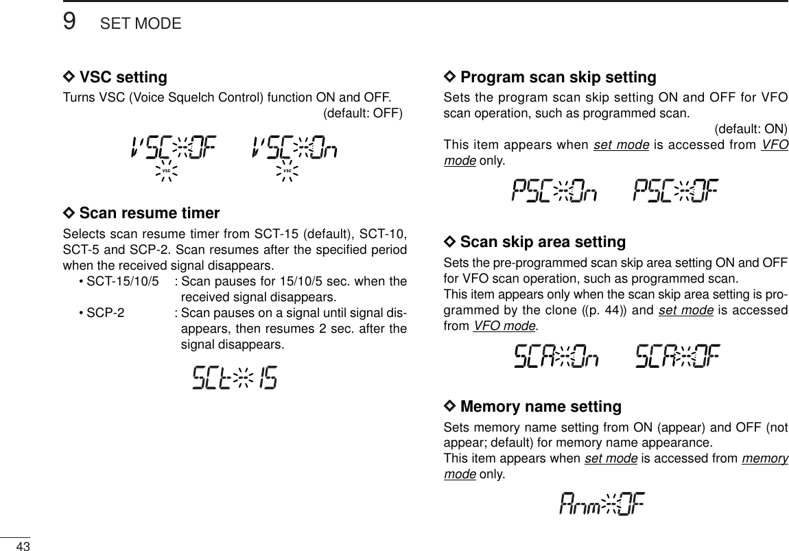
![326SCAN OPERATION6DSkip channel/frequency settingYou can set the selected memory channel as a skip channelwhich is skipped during memory skip scan. In addition, it canbe set as a skip channel for both memory skip scan and fre-quency skip scan. These are useful to speed up the scan in-terval.qSelect a memory channel.➥Push the main band’s [VFO/MR•S.MW] once or twiceto select memory mode, then rotate the same band’s[DIAL] to select the desired memory channel to be askip channel.•“!” and memory channel number appear.wPush and hold [SET•SKIP] for 1 sec. several times to setthe skip condition.• (no indication): The channel is scanned during scan.• ~: The channel is skipped during scan.• P~: The channel is skipped during scan and the pro-grammed frequency is skipped during VFO scan,such as programmed scan.DSkip scan setting [qPush the main band’s [VFO/MR•S.MW] once or twice toselect VFO mode.qPush [SET•SKIP] to enter set mode.wPush [SET•LOCK] or [ATT•PRIO] several times until“PSC” appears.eRotate [DIAL] to toggle the skip scan function ON andOFF.rPush any switch for main band to exit set mode.tThen start the scan to activate the skip scan (memory skipscan or frequency skip scan).[DIAL] [VFO/MR•S.MW] [SET•SKIP][DIAL] [VFO/MR•S.MW] The display shows that memory channel 16 is set as a skip channel.[SET•SKIP]■Skip scan](https://usermanual.wiki/ICOM-orporated/287901/User-Guide-804038-Page-37.png)
![336SCAN OPERATIONThe scan resume condition can be selected as timer or pausescan. The selected resume condition is also used for prioritywatch. (p. 47)qPush [MAIN•AGC] (or [MAIN•NB])to select the desiredband (left or right) as the main band.wPush [SET•SKIP]to enter set mode.ePush [SET•SKIP]or [ATT•PRIO] several times until “SCt”or “SCP” appears.rRotate the main band’s [DIAL] to set the desired timer:•“SCP-2” : Scan pauses until the signal disappears and thenresumes 2 sec. later.•“SCt-15” : Scan pauses 15 sec. while receiving a signal.•“SCt-10” : Scan pauses 10 sec. while receiving a signal.•“SCt-5” : Scan pauses 5 sec. while receiving a signal.tPush any switch for the main band to exit set mode.[DIAL] [ATT•PRIO] [SET•SKIP][MAIN•AGC] [MAIN•NB] [SET•SKIP]The display shows that the scan will resume 15 sec. after it stops.■Scan resume conditionUSINGSET MODE](https://usermanual.wiki/ICOM-orporated/287901/User-Guide-804038-Page-38.png)
![347PRIORITY WATCH12345678910111213141516■Priority watch typesPriority watch checks for signals on the frequency every5sec. while operating on a VFO frequency or scanning. Thereceiver has two priority watch types to suit your needs.The watch resumes according to the selected scan resumecondition. See ((p. 29)) for details.NOTE: If the pocket beep function is activated, the receiverautomatically selects the tone/DTCS squelch functionwhen priority watch starts.■Priority watch operationqPush the main band’s [VFO/MR•S.MW] once or twice toselect VFO mode; then set an operating frequency.wSet the watching channel(s).For memory channel watch:Select the desired memory channel.For memory scan watch:Select memory mode, or the desired bank group; then,push and hold [MODE•SCAN] for 1 sec. to start memoryscan or bank scan.ePush and hold [ATT•PRIO] for 1 sec. to start the watch.•The receiver checks the memory/bank channel(s) every 5 sec.•The watch resumes according to the selected scan resume con-dition. ((p. 29))•While the watch is pausing, pushing and holding [ATT•PRIO] for1 sec. resumes the watch manually.rPush and hold [ATT•PRIO] for 1 sec. to stop the watch.[ATT•PRIO] “PRIO” appearsMEMORY CHANNEL WATCHWhile operating on a VFO fre-quency, priority watch checks fora signal on the selected memorychannel every 5 sec.•Amemory channel with skip infor-mation can be watched.5 sec.VFOfrequency MemorychannelMEMORY SCAN WATCHWhile operating on a VFO fre-quency, priority watch checks forsignals on each memory chan-nel in sequence.•The memory skip function and/ormemory bank scan is useful tospeed up the scan.5 sec.VFOfrequencySKIPMch 000Mch 001Mch 001Mch 999](https://usermanual.wiki/ICOM-orporated/287901/User-Guide-804038-Page-39.png)
![35POCKET BEEP AND TONE SQUELCH8This function uses subaudible tones for calling and can beused as a “common pager” to inform you that someone hascalled while you were away from the receiver.DWaiting for a call from a specific stationqSet the operating frequency in FM mode.wPush [SET•SKIP]to enter set mode in the main band.ePush [SET•SKIP]or [ATT•PRIO] several times until “Ct”(when selecting the tone squelch) or “dt”(when selectingthe DTCS squelch) appears.rRotate the main band’s [DIAL] to select the desired tonefrequency or DTCS code.tWhen operating the pocket beep function with DTCS codesquelch, push [SET•SKIP] once then rotate [DIAL] to se-lect the DTCS polarity.yPush any switch for the main band to exit set mode.uPush and hold [MONI•T/T-SCAN] for 1 sec. to enter tonesquelch selection mode, then rotate [DIAL] until “S”or “ S” appears to turn the pocket beep function ONwith tone squelch or DTCS squelch, respectively.[MONI•T/T-SCAN][DIAL] Appears when the pocket beepwith tone squelch is turned ON. Appears when the pocket beepwith DTCS squelch is turned ON.DTCS polarity setting[DIAL] Tone squelch frequency setting DTCS code setting[ATT•PRIO] [SET•SKIP]■Pocket beep operation](https://usermanual.wiki/ICOM-orporated/287901/User-Guide-804038-Page-40.png)
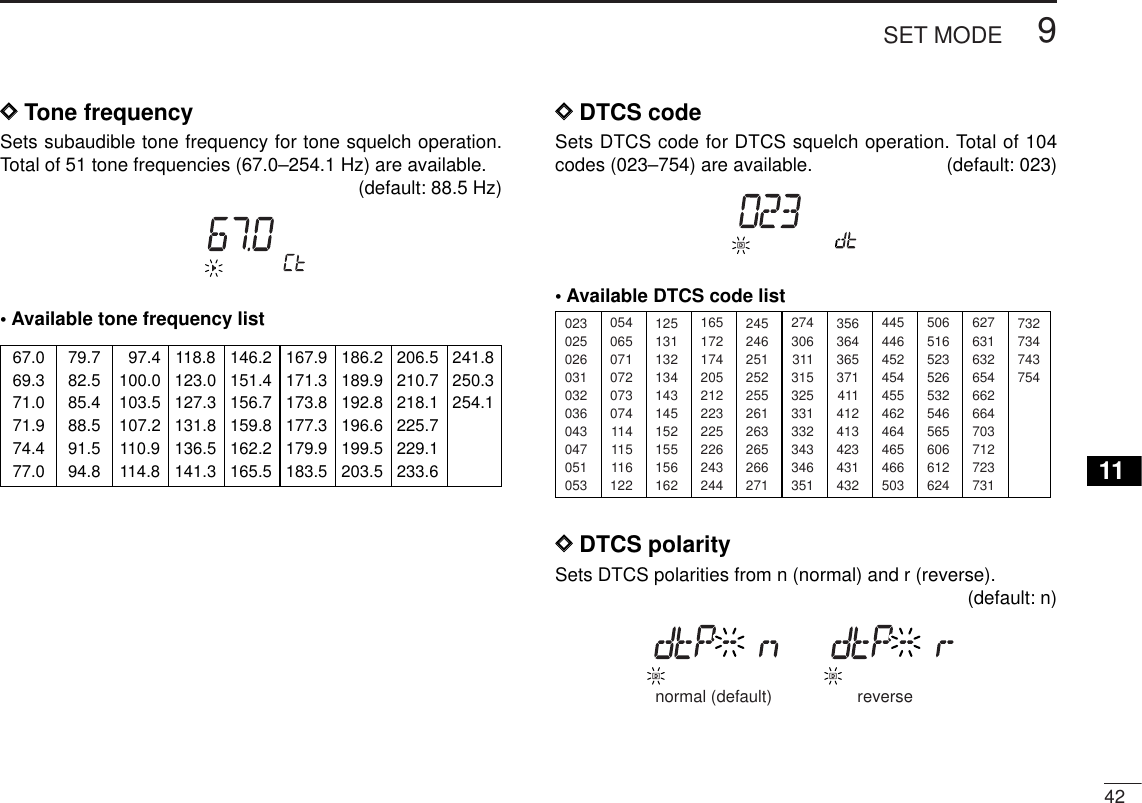
![368POCKET BEEP AND TONE SQUELCH12345678910111213141516iPush any switch for the main band or common switch toexit tone squelch selection mode.oWhen a signal with the matched tone is received, the re-ceiver emits beep tones and blinks “S”.•Beep tones sound for 30 sec. and “S” blinks. To stop thebeeps and blinking manually, push any switch.!0 Push and hold [MONI•T/T-SCAN] for 1 sec. to enter tonesquelch selection mode, then rotate [DIAL] to cancel thetone squelch or DTCS squelch function.•“oFF” is selected for turning the function OFF.DAvailable tone frequency listNOTE: The receiver has 51 tone frequencies and conse-quently their spacing is narrow compared to units having38 tones. Therefore, some tone frequencies may receiveinterference from adjacent tone frequencies.DAvailable DTCS code listDCalling a waiting station using pocket beepAsubaudible tone matched with the station’s CTCSS tone fre-quency or 3-digit DTCS code with polarity is necessary. Usethe tone squelch on the next page ((p. 33)).023025026031032036043047051053125131132134143145152155156162245246251252255261263265266271356364365371411412413423431432506516523526532546565606612624054065071072073074114115116122165172174205212223225226243244274306311315325331332343346351445446452454455462464465466503627631632654662664703712723731732734743754Appears when the pocket beepwith tone squelch is activated. Appears when the pocket beepwith DTCS squelch is activated.67.069.371.071.974.477.079.782.585.488.591.594.8097.4100.0103.5107.2110.9114.8118.8123.0127.3131.8136.5141.3146.2151.4156.7159.8162.2165.5167.9171.3173.8177.3179.9183.5186.2189.9192.8196.6199.5203.5206.5210.7218.1225.7229.1233.6241.8250.3254.1](https://usermanual.wiki/ICOM-orporated/287901/User-Guide-804038-Page-41.png)
![3710 POCKET BEEP AND TONE SQUELCHThe tone or DTCS squelch opens only when receiving a sig-nal with the same pre-programmed subaudible tone or DTCScode, respectively. You can silently wait for the specified sig-nal using the same tone.qSet the operating frequency in FM mode.wProgram the CTCSS tone frequency or DTCS code in setmode. ((p. 31))ePush and hold [MONI•T/T-SCAN] for 1 sec. to enter tone squelch selection mode, then rotate [DIAL] until “ ”or “ ” appears in the function display.rWhen a signal with the matched tone is received, thesquelch opens and the receiver emits audio.•When the received signal includes an unmatched tone, thesquelch does not open. However, the S-meter indicator showsthe received signal strength.•To open the squelch manually, push [MONI•T/T-SCAN].tTo cancel the tone squelch or DTCS squelch function, re-peat steps euntil “oFF” appears, then push any switch.DReverse action for tone or DTCS squelch➥Enter tone squelch selection mode as described in stepsqto eas shown left, then rotate [DIAL] to select eitherreverse action for the tone or DTCS squelch as below.for DTCSfor Tone squelchTone OFF settingDTCS settingTone squelch setting■Tone/DTCS squelch operationHow does the Reverse action work?When the reverse action is selected for either the tonesquelch, “tSqL-r,” or DTCS squelch, “dtCS-r,” and a signalwith the matched tone (or DTCS) is received, the squelchcloses, and the receiver mutes the signal. You can listen inthe signals any other than the specified one, if it’s with tone.](https://usermanual.wiki/ICOM-orporated/287901/User-Guide-804038-Page-42.png)
![3810POCKET BEEP AND TONE SQUELCH10■Tone scanBy monitoring a signal that is being operated with pocketbeep, tone or DTCS squelch function, you can determine thetone frequency or DTCS code necessary to open a squelch.qSet the desired operating frequency or memory channel tobe checked for a tone frequency or code.wPush and hold [MONI•T/T-SCAN] for 1 sec and rotate[DIAL] to select the tone type, tone squelch or DTCS, tobe scanned.•Either “ ” or “ ” appears. ePush and hold [MONI•T/T-SCAN] for 1 sec. to start thetone scan.•To change the scanning direction, rotate [DIAL].rWhen the CTCSS tone frequency or 3-digit DTCS code ismatched, the squelch opens and the tone frequency istemporarily programmed into the selected condition suchas memory channel.•The tone scan pauses when a CTCSS tone frequency or 3-digitDTCS code is detected.•The decoded CTCSS tone frequency or 3-digit DTCS code isused for the tone decoder depending on the selected tone con-dition or type in step w.-“ ”: CTCSS tone decoder-“ ”: DTCS tone decodertPush any switch for the main band or common switch tostop the scan.NOTE: The decoded tone frequency is programmed tem-porarily when a memory is selected. However, this will becleared when the memory channel is re-selected.[MONI•T/T-SCAN]During CTCSS frequency scan During DTCS code scan](https://usermanual.wiki/ICOM-orporated/287901/User-Guide-804038-Page-43.png)
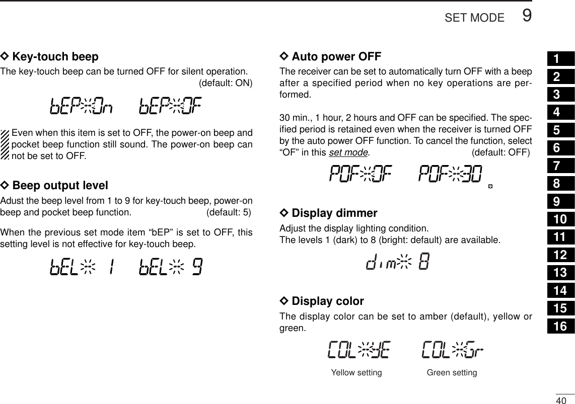
![†Appears when accessing set mode from VFO mode only.‡Appears when accessing set mode from memory mode only.: Push: Push• Weather alert*1When the UT-106 is installed• Display dimmer• Auto power OFF• Key-touch beep • Beep output level • Display color• TSQL frequency• DTCS code• DTCS polarity• Offset frequency• Duplex direction• Display contrast• Scan resume timer • VSC function• Bank link function‡• AFC function*2• NR function*4• ANF function*4• Squelch delay• IF filter• IF shift*3• Program skip†• Scan skip area†• Memory name‡Memory modeonlyFM mode only VFO mode onlySSB/CW mode onlyUSA/CANADA versions only*1Available for USA/CANADA versions only.*2Appears while in FM mode only.*3Appears while in SSB/CW mode only.*4Appears when the UT-106 is selected.SETSKIPATTPRIO■Set mode•Set mode operationqPush the desired band’s [MAIN]to select the main band.wPush [SET•SKIP]to enter set mode.ePush [SET•SKIP]or [ATT•PRIO] to select the desireditem.rRotate the main band’s [DIAL] to select the condition orvalue.tPush any switch for main band or common switch otherthan [SET•SKIP]or [ATT•PRIO] to exit set mode.•Set mode items■Set mode items39SET MODE9](https://usermanual.wiki/ICOM-orporated/287901/User-Guide-804038-Page-44.png)
![419SET MODEDDDisplay contrastThe LCD contrast can be adjusted through 9 levels.(default: 5)DDDuplex directionSets the duplex direction. The displaying frequency shifts theprogrammed offset frequency (below) when monitor functionis in use (pushing [MONI•T/T-SCAN]).•OFF : Simplex operation. (default)•DUP– : The displaying frequency shifts down duringmonitor.•DUP+ : The displaying frequency shifts up during moni-tor.DDOffset frequencySets the duplex offset frequency for each frequency band in-dependently within 0 to 1000 MHz range. During duplex op-eration (DUP– or DUP+), the monitoring frequency (pushing[MONI•T/T-SCAN]) shifts the set frequency.The default value may differ according to the selected fre-quency band (before accessing set mode)and receiver version.The selected tuning step in VFO mode is used for settingthe offset frequency.](https://usermanual.wiki/ICOM-orporated/287901/User-Guide-804038-Page-46.png)
![449SET MODE12345678910111213141516DDMemory bank link functionSets the memory bank link function ON and OFF (default).The link function provides continuous banks scan, that scansall contents in the selected banks during bank scan.This item appears when set mode is accessed from memorymode only.•Bank link settingqRotate [DIAL] to select the memory bank link function ON.wPush and hold [SET•LOCK] or [S.MW•MW] for 1 sec. toenter bank link setting mode.ePush [SET•LOCK] or [S.MW•MW] to select the desiredbank to be linked.•A: Bank A • b : Bank B • C : Bank C • d : Bank D• E : Bank E • F : Bank F • G : Bank G • H : Bank H• J : Bank J • k : Bank K • L : Bank L • m: Bank M• n : Bank N • o : Bank O • P : Bank P • q : Bank Q• r : Bank R • t : Bank T • U : Bank U • W: Bank W• y : Bank YrRotate [DIAL] to select “On” to linking the bank.tRepeat steps eand rto set the link condition.yPush [TS•MODE] or any switch below the display to returnto set mode.DDAFC settingTurns AFC (Automatic Frequency Control) function ON andOFF. (default: OFF)DDFilter settingSelect the IF filter passband width from 3, 6, 15, 50 and 230(depending on the selected mode.)DDWeather alert functionTurns weather alert function ON and OFF.U.S.A./CANADA versions onlyBank A ON Bank A OFF](https://usermanual.wiki/ICOM-orporated/287901/User-Guide-804038-Page-49.png)
![4910 OTHER FUNCTIONS■Partial resetIf you want to initialize the operating conditions (VFO fre-quency, VFO settings, set mode contents) without clearingthe memory contents, a partial resetting function is availablefor the receiver left and right bands independently.➥While pushing desired band’s [VFO/MR•S.MW], turn thepower ON to partially reset the desired band (left or right).✔Hint!When pushing both [VFO/MR•S.MW] and turning the powerON, partially reset both bands at the same time.■ALL resetThe function display may occasionally display erroneous in-formation (e.g. when first applying power). This may becaused externally by static electricity or by other factors.If this problem occurs, turn power OFF. After waiting a fewseconds, turn power ON again. If the problem persists, per-form the following procedure.•Partial resetting is also available. See left for details.IMPORTANT!:Resetting the receiver CLEARS all memory informationand initializes all values in the receiver.➥While pushing both band’s [MHz•TS], turn the power ONto reset the CPU.[MHz•TS]While pushing both [MHz•TS], turn power ON.[MHz•TS]ATPOWER ONLeft band partial reset.Right band partial reset.ATPOWER ON](https://usermanual.wiki/ICOM-orporated/287901/User-Guide-804038-Page-52.png)