ICOM orporated 289401 UHF Transceiver User Manual Manual
ICOM Incorporated UHF Transceiver Manual
UserManual.wiki
>
ICOM orporated
>
289401 User Manual
Manual
Navigation menu
Upload a User Manual
Namespaces
Wiki Guide
HTML
PDF
Info
Views
User Manual
Discussion / Help
Navigation
![PRECAUTIONSiiRCAUTION! NEVER hold the transceiver so that theantenna is very close to, or touching exposed parts of thebody, especially the face or eyes, while transmitting. Thetransceiver will perform best if the microphone is 2 to 4 in. (5to 10 cm) away from the lips and the transceiver is vertical.RCAUTION! NEVER operate the transceiver with aheadset or other audio accessories at high volume levels. RCAUTION! NEVER short the terminals of the bat-tery pack.DO NOT push [PTT] when not actually desiring to trans-mit.AVOID using or placing the transceiver in direct sunlight orin areas with temperatures below +22°F (–30°C) or above+140°F (+60°C).The basic operations, transmission and reception of the trans-ceiver are guaranteed within the specified operating temper-ature range. However, the LCD display may not be operatecorrectly, or show an indication in the case of long hours ofoperation, or after being placed in extremely cold areas. DO NOT modify the transceiver for any reason.KEEP the transceiver from the heavy rain, and Neverimmerse it in the water. The transceiver construction is waterresistant, not waterproof.The use of non-Icom battery packs/chargers may impairtransceiver performance and invalidate the warranty.For U.S.A. onlyCAUTION: Changes or modifications to this transceiver, notexpressly approved by Icom Inc., could void your authority tooperate this transceiver under FCC regulations.](https://usermanual.wiki/ICOM-orporated/289401/User-Guide-660111-Page-3.png)
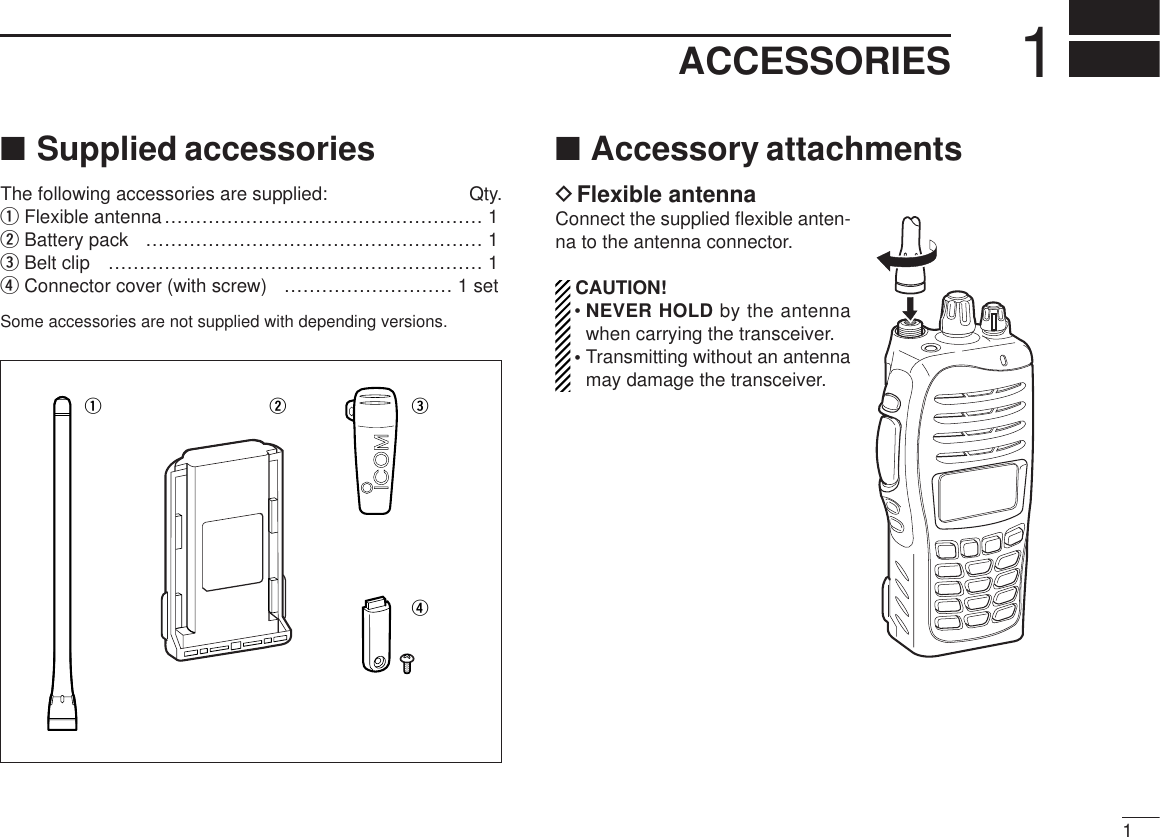
![42PANEL DESCRIPTION■Front panelqROTARY SELECTORRotate to select the pre-programmed memory channels orthe operating zone.(Depending on the pre-setting)wANTENNA CONNECTORConnects the supplied antenna.eDEALER-PROGRAMMABLE KEY [Emer]Desired functions can be programmed by your dealer. ((☞ p. 7))rDEALER-PROGRAMMABLE KEY [Side1]Desired functions can be programmed by your dealer. ((☞ p. 7))tPTT SWITCH [PTT]Push and hold to transmit; release to receive.yDEALER-PROGRAMMABLE KEYS [Side2]/[Side3]Desired functions can be programmed independently byyour dealer. ((☞ p. 7))u10-KEYPAD (Depending on version)The keypad allows you to enter digits to:• Select memory channels• Select tone channels• Select DTMF codes (during transmit)• Set TX codes• Start up with the passwordiDEALER-PROGRAMMABLE KEYS [P0] to [P3]Desired functions can be programmed independently byyour dealer. ((☞ p. 7))oFUNCTION DISPLAYDisplays a variety of information such as an operatingchannel number/name, 2-tone code, DTMF numbers,selected function, etc.wetryq!1!0o!2uiMicrophoneSpeaker](https://usermanual.wiki/ICOM-orporated/289401/User-Guide-660111-Page-8.png)
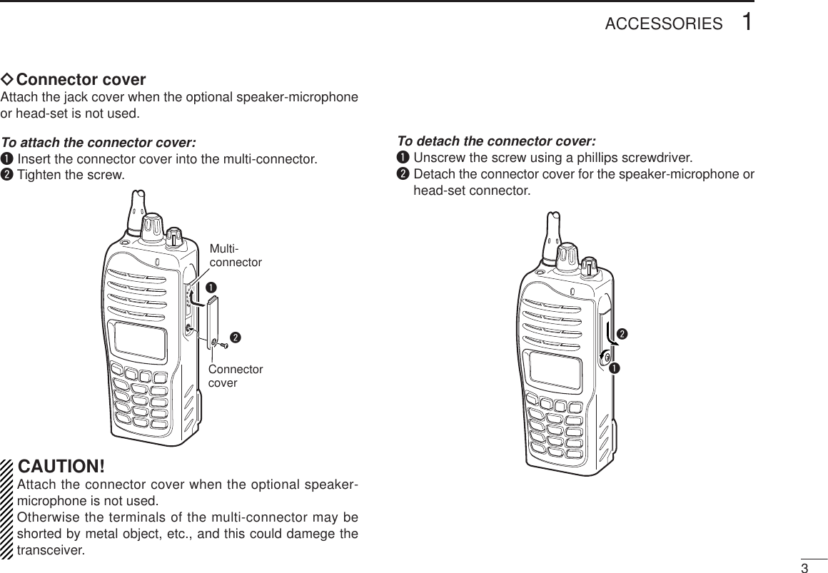
![52PANEL DESCRIPTION!0 MULTI-CONNECTORConnect an optional speaker-microphone.!1 BUSY/TRANSMIT INDICATOR➥ Lights green while receiving a signal, or when thesquelch is open.➥ Lights red while transmitting.!2 VOLUME CONTROL [VOL]Rotate to turn the power ON/OFF and adjusts the audiolevel.Connector coverNOTE: Attach the connector cover when the optional speak-er-microphone is not used. See ((☞ p. 3)) for details.](https://usermanual.wiki/ICOM-orporated/289401/User-Guide-660111-Page-9.png)
![62PANEL DESCRIPTION■Function displayqSIGNAL STRENGTH INDICATORIndicates relative signal strength level.wLOW POWER INDICATORAppears when low output power is selected.eAUDIBLE INDICATOR➥Appears when the channel is in the ‘audible’ (unmute)condition.➥Appears when the specified 2-tone is received.rCOMPANDER INDICATORAppears when the compander function is activated.tSCRAMBLER INDICATORAppears when the voice scrambler function is activated.yBELL INDICATOR➥Appears/blinks when the specific 2-tone/DTMF selectcall is received, according to the pre-programming.uCALL CODE MEMORY INDICATORAppears when the call code memory is selected.iBATTERY INDICATORAppears or blinks when the battery power decreases to aspecified level.oALPHANUMERIC DISPLAY➥Displays an operating channel number, channel name,Set mode contents, DTMF code, etc. ➥The indication mode can be selected from 1 line or 2lines. Ask your dealer for details.• In this instruction manual, the LCD illustration is describedusing the 2 lines indication mode.!0 KEY INDICATORIndicate the programmed function of the front panel keys([P0], [P1], [P2] and [P3]).q t iuyrewo!0](https://usermanual.wiki/ICOM-orporated/289401/User-Guide-660111-Page-10.png)
![72PANEL DESCRIPTION■Programmable function keysThe following functions can be assigned to [Emer],[Side1],[Side2], [Side3], [P0], [P1], [P2] and [P3] programmablefunction keys. Consult your Icom dealer or system operator for details con-cerning your transceivers programming.If the programmable function names are bracketed in the fol-lowing explanations, the specific key is used to activate thefunction depends on the programming.CH UP AND DOWN KEYS “UUPP” “DDOOWWNN”➥Push to select an operating channel.➥Push to select a transmit code channel after pushing [TXCode CH Select].➥Push to select a DTMF channel after pushing [DTMFAutodial].➥Push to select a scan group after pushing and holding[Scan A Start/Stop]/[Scan B Start/Stop].ZONE KEY “ZZOONNEE”Push this key, then push [CH Up] or [CH Down] to select thedesired zone.What is “zone”?— The desired channels are assignedinto a zone according to the intended use for grouping. Forexample, ‘Staff A’ and ‘Staff B’ are assigned into a“Business” zone, and ‘John’ and ‘Cindy’ are assigned into a“Private” zone.SCAN A KEY “SSCCNNAA”➥This key’s operation depends on the Power ON Scan set-ting.When the power ON scan function is turned OFF;Push to start and cancel scanning operation. In case oftransmission during scan, cancels scanning.When the power ON scan function is turned ON;Push to pause scanning., then resumes scanning afterpassing a specified time period. In case of transmissionduring scan, scanning will be canceled.➥Push and hold this key for 1 sec. to indicate the scangroup, then push [CH Up] or [CH Down] to select thedesired group.SCAN B KEY “SSCCNNBB”➥Push to start and cancel scanning operation. In case oftransmission during scan, pauses scanning. Scanningresumes after passing a specified time period. ➥Push and hold this key for 1 sec. to indicate the scangroup, then push [CH Up] or [CH Down] to select thedesired group.](https://usermanual.wiki/ICOM-orporated/289401/User-Guide-660111-Page-11.png)
![82PANEL DESCRIPTIONSCAN ADD/DEL (TAG) KEY “SSCCAADD”Push to add or delete the selected channel to/from the scangroup.PRIO A/B KEYS “PPRRAA” “PPRRAARR” “PPRRBB” “PPRRBBRR”➥Push to select Priority A or Priority B channel.➥Push and hold [Prio A (Rewrite)] to rewrite the Prio A chan-nel.MR-CH 1/2/3/4 KEYS “CCHH11” “CCHH22” “CCHH33” “CCHH44”Push to select an operating channel directly.MONI KEY “MMOONN”Mute and release the CTCSS (DTCS) or 2-tone squelchmute. Open any squelch/deactivate any mute while pushingthis key.LIGHT KEY “LLIIGGTT”Push to turn the transceiver’s backlight ON temporarily onlywhen the backlight function is turned OFF in user set mode. LOCK KEY “LLOOCCKK”➥Push and hold for 1 sec. to electronically lock all program-mable keys except the following:[Call] (incl. Call A and Call B), [Moni(Audi)] and[Emergency].➥Push and hold for 1 sec. again to turn the lock functionOFF.HIGH/LOW KEY “HH//LL”Push to select the transmit output power temporarily or per-manently, depending on the pre-setting.•Ask your dealer for the output power level for each selection.C.TONE CH ENT KEY “TTSSEELL”Push to select the continuous tone channel using [CH Up]/[CH Down] to change the tone frequency/code set-ting. The selected channel remains set as the continuoustone channel until another channel is designated as such.TALK AROUND KEY “TTAA”Push to turn the talk around function ON and OFF.•The talk around function equalizes the transmit frequency to thereceive frequency for transceiver-to-transceiver communication.WIDE/NARROW KEY “WW//NN”Push to toggle the IF bandwidth between wide and narrow.DTMF AUTODIAL KEY “DDTTMMAA”➥Push to enter the DTMF channel selection mode. Thenselect the desired DTMF channel using [CH Up]/[CHDown].➥After selecting the desired DTMF channel, push this key totransmit the DTMF code.RE-DIAL KEY “DDTTMMRR”Push to transmit the last-transmitted DTMF code.](https://usermanual.wiki/ICOM-orporated/289401/User-Guide-660111-Page-12.png)
![92PANEL DESCRIPTIONCALL KEYS “CCAALLLL” “CCAALLAA” “CCAALLBB”Push to transmit a 2-tone.•Call transmission is necessary before you call another stationdepending on your signaling system.•[Call A] and/or [Call B] may be available when your system employsselective ‘Individual/Group’ calls. Ask your dealer which call isassigned to each key.EMERGENCY KEY “EEMMRR”Push and hold for a specified period to transmit an emer-gency call.• If you want to cancel the emergency call, push (or push and hold)the key again before transmitting the call.• The emergency call is transmitted one time only or repeatedly untilreceiving a control code depending on the pre-setting.SURVEILLANCE KEY “SSUURRVV”Push to turn the surveillance function ON or OFF.When this function is turned ON, the beep is not emitted andthe LCD backlight does not light when a signal is received ora key is pushed, etc.TX CODE CHANNEL SELECT KEY “TTXXCC”➥Push to enter the ID code channel selection mode directly.Then set the desired channel using [CH Up]/[CH Down].((☞p. 15))TX CODE CHANNEL UP/DOWN KEYS “TTXXCCUU” “TTXXCCDD”Push to select a TX code channel directly.SCRAMBLER FUNCTION “SSCCRR”Push to toggle the voice scrambler function ON and OFF.COMPANDER KEY “CCOOMMPP”Push to toggle the compander function ON and OFF. The compander function reduces noise components from thetransmitting audio to provide clear communication.PHONE KEY “PPHHNN”Push to connect or disconnect the telephone network con-nection during LTR operation.USER SET MODE KEY “SSEETT”➥Push and hold to enter user set mode.• During user set mode, push this key to select an item, andchange the value or condition using push [CH Up]/[CH Down].➥Push and hold this key again to exit user set mode.User set mode is also available via the ‘Power ON function.’Refer to ((☞p. 16)) also.OPT OUT KEYS “OOPP11” “OOPP22” “OOPP33”Push to control the output signal level of the optional ports inthe optional unit connector.OPT MOMENTARY KEYS “OO11MM” “OO22MM” “OO33MM”Push and hold to control the output signal level of the option-al ports in the optional unit connector.](https://usermanual.wiki/ICOM-orporated/289401/User-Guide-660111-Page-13.png)
![■Turning power ONPrior to using the transceiver for the first time, the batterypack must be fully charged for optimum life and operation.((☞p. 20))qRotate [VOL] to turn the power ON.wIf the transceiver is programmed for a start up password,input the digit codes as directed by your dealer.• 10-keypad can be used for password input depending on ver-sion:• The keys in the table below can be used for password input:• The transceiver detects numbers in the same block as identical.Therefore “01234” and “56789” are the same.eWhen the “PASSWORD” indication does not clear afterinputting 4 digits, the input code number may be incorrect.Turn the power off and start over in this case.■Channel selectionSeveral types of channel selections are available. Methodsmay differ according to your system set up.NON-ZONE TYPE:Push [CH Up] or [CH Down], or rotate [ROTARY SELEC-TOR]* to select the desired operating channel, in sequence;or, push one of [MR-CH 1] to [MR-CH 4] keys to select achannel directly.• Up to 16 pre-programmed channels can be selected via [ROTARYSELECTOR].*ZONE TYPE:Push [Zone], then push [CH Up] or [CH Down] or rotate[ROTARY SELECTOR]* to select the desired zone.AUTOMATIC SCAN TYPE:Channel setting is not necessary for this type. When turningpower ON, the transceiver automatically starts scanning.Scanning stops when receiving a call.*Depending on the pre-setting.KEYNUMBER 0549382716(Side3)103BASIC OPERATION](https://usermanual.wiki/ICOM-orporated/289401/User-Guide-660111-Page-14.png)
![113BASIC OPERATION■Call procedureWhen your system employs tone signaling (excluding CTCSSand DTCS), the call procedure may be necessary prior to voicetransmission. The tone signaling employed may be a selectivecalling system which allows you to call specific station(s) onlyand prevent unwanted stations from contacting you.qSelect the desired TX code channel or 2-tone codeaccording to your System Operator’s instructions.• This may not be necessary depending on programming.• Refer to ((☞ pages. 14 or 15)) for selection.wPush the call key (assigned to one of the dealer program-mable keys: [Emer], [Side1], [Side2], [Side3], [P0], [P1],[P2] and [P3]) or [PTT].eAfter transmitting a 2-tone code, the remainder of yourcommunication can be carried out in the normal fashion.Selective calling Non-selective calling](https://usermanual.wiki/ICOM-orporated/289401/User-Guide-660111-Page-15.png)
![■Receiving a callDGroup callqPush [CH Up] or [CH Down], or rotate [ROTARY SELEC-TOR]* to select the LTR system channel or talk group.wWhen a call is received;•‘BUSY’ indicator lights green.ePush and hold [PTT], then speak into the microphone at anormal voice level.rRelease [PTT] to return to receive.DSelective call (DTMF call)qPush [CH Up] or [CH Down], or rotate [ROTARY SELEC-TOR]* to select the LTR system channel or talk group.wPush [Call] to mute the channel.eWhen receiving a call, the calling station name appearsand a beep is emitted. Then the mute is released.•“”appears.*:Depending on the pre-setting.DPhone call• Receive a phone callqPush [CH Up] or [CH Down], or rotate [ROTARY SELEC-TOR]* to select the phone channel of LTR system chan-nel.•“”appears.wWhen a phone call is received (transceiver rings), push[PHONE] (or push [PTT]).•“”blinks.ePush and hold [PTT], then speak into the microphone at anormal voice level. Release [PTT] to return to receive.rAfter conversation is finished, push [PHONE] (or whilepushing and holding [PTT], push [#]) to disconnect thephone call.•“”stops blinking.002 ch-03fH 173.7MBlinks002 ch-03fH 173.7MAppears124LTR OPERATION](https://usermanual.wiki/ICOM-orporated/289401/User-Guide-660111-Page-16.png)
![134LTR OPERATION• Make a phone callqSelect the phone channel of LTR system channel.•“”appears.wPush [PHONE] (or push [PTT]).•“”blinks.ePush [DTMF Autodial] (or while pushing and holding [PTT]enter the desired telephone number using 10 key pad) tomake a phone call.rAfter conversation is finished, push [PHONE] (or whilepushing and holding [PTT], push [#]) to disconnect thephone call.•“”stops blinking.*:Depending on the pre-setting.■Transmitting a callDGroup callqPush [CH Up] or [CH Down], or rotate [ROTARY SELEC-TOR]* to select the LTR system channel or talk group.wWhile pushing and holding [PTT], speak into the micro-phone at a normal voice level after a beep is emitted.• If an error beep is emitted, release [PTT]. After a while, repeatstep w.• The beep can be turned OFF in User set mode.DSelective call (DTMF call)qPush [CH Up] or [CH Down], or rotate [ROTARY SELEC-TOR*] to select the LTR system channel or talk group.wPush [DTMF Autodial]— a DTMF encode channelappears.ePush [CH Up] or [CH Down] to select the desired DTMFencode channel.rPush [PTT] to transmit the selected DTMF code in theselected DTMF channel.• Push [DTMF Autodial] to cancel the DTMF transmission.002 ch-03fH 173.7MBlinks](https://usermanual.wiki/ICOM-orporated/289401/User-Guide-660111-Page-17.png)
![145CONVENTIONAL OPERATION■Receiving and transmittingNOTE: Transmitting without an antenna may damage thetransceiver. See ((☞p. 1)) for accessory attachments.Receiving:qRotate [VOL] to turn the power ON.wPush [CH Up] or [CH Down], or rotate [ROTARY SELEC-TOR]* to select the conventional system channel, insequence.*Depending on the pre-setting.eWhen receiving a call, adjust the audio output level to acomfortable listening level.Transmitting:Wait for the channel to become clear to avoid interference.qPush [Call] when initiating a call from your side.• Coded audio may be heard from the transceiver, then “”appears.• This operation may not be necessary depending on your signal-ing system. Ask your dealer for details.wWhile pushing and holding [PTT], speak into the micro-phone at a normal voice level.eRelease [PTT] to return to receive.IMPORTANT: To maximize the readability of your signal;1. Pause briefly after pushing [PTT].2. Hold the microphone 5 to 10 cm (2 to 4 inches) fromyour mouth, then speak into the microphone at a nor-mal voice level.DTransmitting notes• Transmit inhibit functionThe transceiver has several inhibit functions which restricttransmission under the following conditions:- The channel is in mute condition (‘Inaudible’ condition; “” does not appear.)- The channel is busy.- Un-matched (or matched) CTCSS is received.(Depending on the pre-setting.)- The selected channel is a ‘receive only’ channel.• Time-out timerAfter continuous transmission for the pre-programmed timeperiod, the time-out timer is activated, causing the transceiv-er to stop transmitting.• Penalty timerOnce the time-out timer is activated, transmission is furtherinhibited for a period determined by the penalty timer.](https://usermanual.wiki/ICOM-orporated/289401/User-Guide-660111-Page-18.png)
![155CONVENTIONAL OPERATIONDTX code channel selectionIf the transceiver has [TX Code CH Select] assigned to it, theindication can be toggled between the operating channelnumber (or name) and TX code channel number (or name).When the TX code channel number (or name) is displayed,[CH Up] or [CH Down] selects the TX code channel.USING [TX CODE CH SELECT] KEY: qPush [TX Code CH Select]— a TX code channel number(or name) appears.wPush [CH Up] or [CH Down] to select the desired TX codechannel.ePush [Call] (or [PTT] during MSK operation) to transmit theselected TX code.rPush [TX Code CH Select] again to return to the operat-ing channel number indication.USING [TX CODE CH UP]/[TX CODE CH DOWN] KEY:If the transceiver has a [TX Code CH Up] or [TX Code CHDown] key assignment, the programmed TX code channelcan be selected directly when pushed.DDTMF transmissionIf the transceiver has [DTMF Autodial] assigned to it, the auto-matic DTMF transmission function is available. Up to 8 DTMFchannels are available.TO SELECT A TX CODE:qPush [DTMF Autodial]— a DTMF channel appears.wPush [CH Up] or [CH Down] to select the desired DTMFchannel.ePush [DTMF Autodial] to transmit the DTMF code in theselected DTMF channel.](https://usermanual.wiki/ICOM-orporated/289401/User-Guide-660111-Page-19.png)
![165CONVENTIONAL OPERATION■User set modeUser set mode is accessed at power ON and allows you toset seldom-changed settings. In this case you can “cus-tomize” the transceiver operation to suit your preferences andoperating style.Entering the user set mode:qWhile pushing and holding [P1] and [P2], rotate [VOL] toturn the power ON. Then, push and hold [P0] to enter userset mode. wPush [P0] several times to select the appropriate item.Then push [Side2] or [Side3] to set the desired level/con-dition.• Available set mode functions are Backlight, LCD contrast,Beep, Beep Level, Ringer Level, SQL Level, AF Min Level,Mic Gain, VOX Gain, VOX Delay, Battery Voltage and SignalMoni.eRotate [VOL] to turn the power OFF to exit user set mode.NOTE: User set mode is also available via a programma-ble key. Please refer to ((☞p. 9)) [User Set Mode] section.■Emergency transmissionWhen [Emergency Single] or [Emergency Repeat] is pushed,an emergency signal is automatically transmitted for the spec-ified time period.When [Emergency] is pushed, the DTMF emergency signalis transmitted on the priority channel.When [Emergency Single] or [Emergency Repeat] is pushedfor the specified time period, the DTMF emergency signal istransmitted once or repeatedly on the emergency channel.However, when no emergency channel is specified, the signalis transmitted on the previously selected channel.■Scrambler functionThe voice scrambler function provides private communicationbetween stations. The frequency inversion type is equippedto all versions, moreover, the optional Rolling or Non-rollingtype can be available.qPush [Scrambler] to turn the scrambler function ON.• “ ” appears.wPush [Scrambler] again to turn the scrambler functionOFF.• “ ” disappears.](https://usermanual.wiki/ICOM-orporated/289401/User-Guide-660111-Page-20.png)
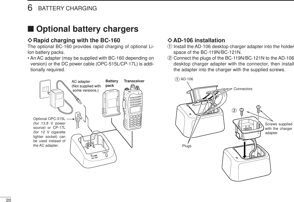
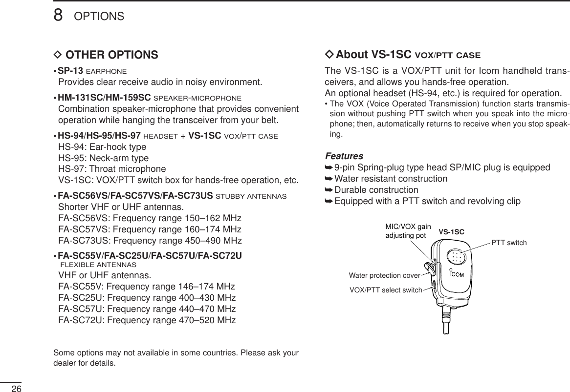
![278OPTIONSVOX gain and delay adjustmentqAttach the connector of the VS-1SC into the multi-connec-tor on the transceiver and tighten the screw.• Toggle the VOX/PTTselect switch to [VOX].wEnter user set mode. ((☞p. 16)) ePush [P0] several times to select the “VOX Gain” or “VOXDelay” items. Then, push [Side2] or [Side3] to set thedesired level/condition.rRotate [VOL] to turn the power OFF to exit user set mode.• VOX GainThe VOX sensitivity level can be adjusted from OFF or 1 to 6(more sensitive).• VOX DelayThe VOX delay time can be set from 0.5 to 3.0 sec. (0.5 sec.step) for a convenient interval before returning to receive.NOTE: MIC/VOX gain can be adjusted via the Adjustingpot using a thin screw driver.0.5 sec (min.)(default)XTXCSET3.0 sec (max.)XTXCSET[Side2]Push[Side3]VOX function is OFFXTXCSETVOX gain level 3(default)XTXCSET[Side2]Push[Side3]](https://usermanual.wiki/ICOM-orporated/289401/User-Guide-660111-Page-31.png)