ICOM orporated 290500 VHF Marine Transceiver User Manual Manual
ICOM Incorporated VHF Marine Transceiver Manual
UserManual.wiki
>
ICOM orporated
>
290500 User Manual
Manual
Navigation menu
Upload a User Manual
Namespaces
Wiki Guide
HTML
PDF
Info
Views
User Manual
Discussion / Help
Navigation
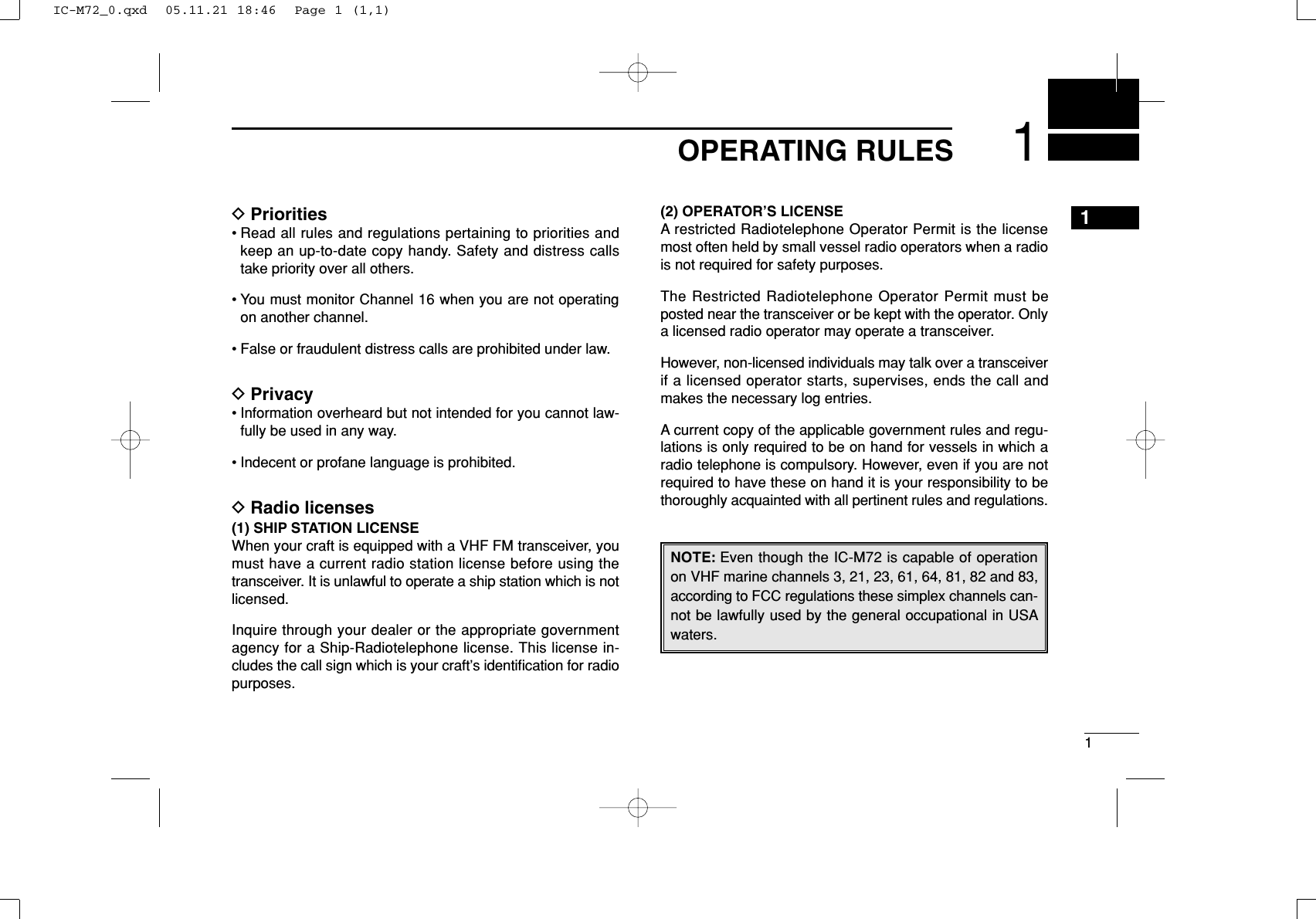
![4PANEL DESCRIPTIONNew20013■Front, top and side panelsqVOLUME CONTROL [VOL]Turns power ON and adjusts the audio level.wPTT SWITCH [PTT]Push and hold to transmit; release to receive.eMONITOR KEY [ ]• Manually opens the squelch for monitoring the channelwhile pushed and held. (p. 10)• Push this switch, then adjust the squelch level with[YY]/[ZZ]. (p. 11)• While pushing and holding this switch, turn power ON toenter the set mode. (p. 17)rCHANNEL UP/DOWN KEYS [YY]/[ZZ]• Selects an operating channel. (pgs. 7–9)• Selects the SET mode condition of the item. (p. 17)• Selects the SET mode item when pushed with [].(p. 17)• Checks TAG channels or changes scanning direction dur-ing scan. (p. 15)tCHANNEL 16 KEY [16•9]• Selects Channel 16 when pushed. (p. 7)• Selects call channel when pushed for 1 sec. (p. 7)• Enters call channel write mode when the call channel isselected and this key is pushed and held for 3 sec. (p. 10)qwertMicrophone!0oiuySpeakerFunctiondisplay(p. 5)IC-M72_0.qxd 05.11.21 18:46 Page 4 (1,1)](https://usermanual.wiki/ICOM-orporated/290500/User-Guide-623774-Page-10.png)
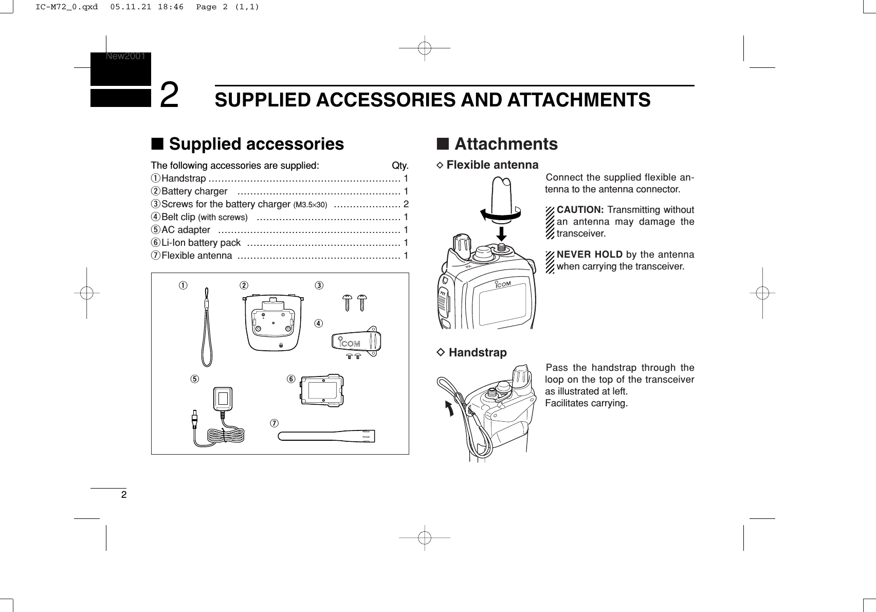
![53PANEL DESCRIPTIONNew2001yTRANSMIT POWER/LOCK KEY [H/L•LOCK]• Selects high, middle or low power when pushed. (p. 9)• Toggles the lock function ON/OFF when pushed and heldfor 1 sec. (p. 10)uSCAN KEY [SCAN•DUAL]• Starts and stops normal or priority scan when pushed.(pgs. 14, 15)• Enters watch mode when pushed and held for 1 sec.(p. 16)iCHANNEL/WEATHER CHANNEL KEY [CH/WX•U/I/C]• Selects and toggles the regular channels and weatherchannel when pushed. (p. 8)• Selects one of 3 regular channels in sequence whenpushed and held for 1 sec. (p. 8)- U.S.A., International and Canadian* channels are avail-able. *Available with the USA versions only.• Push to return to the condition before selecting the chan-nel when the priority channel or the call channel is se-lected.oSPEAKER-MICROPHONE CONNECTOR [SP MIC]Connects the optional external speaker-microphone orheadset.NOTE: Attach the [SP MIC] cap when the optionalspeaker-microphone or headset is not used.!0 ANTENNA CONNECTORConnects the supplied antenna.■Function displayqCHANNEL NUMBER READOUT• Indicates the selected operating channel number.• In SET mode, indicates the selected condition.• “DUP” appears when a duplex channel is selected.wTAG CHANNEL INDICATOR (p. 15)Appears when TAG channel is selected.eBATTERY INDICATORIndicates remaining battery power.IndicationFull Middle Chargingrequired No batteryBattery levelblinks when the battery is over charged.qwertyuio!0!1!2!3!4!53IC-M72_0.qxd 05.11.21 18:46 Page 5 (1,1)](https://usermanual.wiki/ICOM-orporated/290500/User-Guide-623774-Page-11.png)
![74BASIC OPERATION34■Channel selectionIMPORTANT!: Prior to using the transceiver for the firsttime, the battery pack must be fully charged for optimumlife and operation. To avoid damage to the transceiver, turnthe power OFF while charging.DChannel 16Channel 16 (Distress channel) is used for establishing initialcontact with another station and for emergency communica-tions. Channel 16 is automatically monitored during bothdualwatch and tri-watch. While standing by, you must monitorChannel 16.qPush [16•9] to select Channel 16.wPush [CH/WX•U/I/C] to return to the condition before se-lecting Channel 16, or push [YY]/[ZZ]to select the operatingchannel.DChannel 9 (Call channel)Channel 9 is the leisure-use call channel. Each regularchannel group has separate call channels. In addition, the callchannel is monitored during tri-watch. The call channels canbe re-programmed (p. 10) and may be used to store your mostoften used channels in each channel group for quick recall.qPush and hold [16•9] for 1 sec. to select the call channel.•“CALL” and the call channel number appear.•Call channel can be re-programmed. See the “Call channelprogramming” on p. 10 for details.wPush [CH/WX•U/I/C] to return to the condition before se-lecting Channel 9 (call channel), or push [YY]/[ZZ]to selectthe operating channel.Pushfor 1 sec.PushIC-M72_0.qxd 05.11.21 18:46 Page 7 (1,1)](https://usermanual.wiki/ICOM-orporated/290500/User-Guide-623774-Page-13.png)
![DU.S.A., International and Canadian channelsThe IC-M72 has 57 U.S.A., 57 International and 61 Cana-dian* channels. You must select the proper channels for theoperating area. *Available with the USA versions only.qPush [CH/WX•U/I/C] to select the regular channel.•If the weather channel appears, push [CH/WX•U/I/C] again.wPush [YY]/[ZZ]to select a channel.•“DUP” appears for duplex channels.eTo change the channel group, push and hold[CH/WX•U/I/C] for 1 sec.•U.S.A., International and Canadian channels can be selected insequence. DWeather channelsThe IC-M72 has 10 weather channels. They are used formonitoring NOAA (National Oceanographic and Atmospheric Ad-ministration) broadcasts (reception of weather channels possible inU.S.A. only).qPush [CH/WX•U/I/C] to select the weather channel group.wPush [YY]/[ZZ]to select a weather channel.ePush [CH/WX•U/I/C] to return to the condition before se-lecting the weather channel group.✔CONVENIENT!The IC-M72 can detect a weather alert tone on theselected weather channel while in another channel (when thepower save function is turned ON) or during scanning. See the“SET mode items” on p. 18 for details.PushPush for 1 sec.U.S.A. channelInternational channel Canadian channel84BASIC OPERATIONNew2001IC-M72_0.qxd 05.11.21 18:46 Page 8 (1,1)](https://usermanual.wiki/ICOM-orporated/290500/User-Guide-623774-Page-14.png)
![94BASIC OPERATIONNew20014■Receiving and transmittingqRotate [VOL] clockwise to turn power ON.•Opening comment scrolls. (p. 13)•Push [16•9] to skip the opening comment indication.wSet the volume and squelch level.➥Push [], and push [ZZ]to open the squelch.➥Rotate [VOL] to set the volume level.➥Push [], and push [YY]/[ZZ]to set the squelch level.ePush [YY]/[ZZ]to select the desired channel.- When receiving a signal, “” indicator appears while audio isemitted from the speaker.- Further adjustment of [VOL] may be necessary at this point.rPush [H/L•LOCK] to select the output power if necessary.- “LOW” appears when low power is selected; “MID” appearswhen middle power is selected; no indication when high power isselected.- Choose low power to conserve battery power, choose highpower for longer distance communications.- Some channels are for low power only.tPush and hold [PTT] to transmit, then speak into the mi-crophone.- The transmit indicator appears while transmitting.- Channel 70 cannot be used for transmission.yRelease [PTT] to receive.IMPORTANT: To maximize the readability of your trans-mitted signal, pause a few sec. after pushing [PTT], holdthe microphone 5 to 10 cm (2 to 4 inches) from your mouthand speak into the microphone at a normal voice level.NOTE: The transceiver has a power save function to con-serve the battery power. The power save function activatesautomatically when no signal is received for 5 sec.To prevent accidental prolonged transmission, etc., the IC-M72 has a time-out timer function. This timer cuts a trans-mission OFF after 5 min. of continuous transmission.MicrophoneSpeakerr Set output powert Push to transmity Release to receive q Power ONw Set volumew Set the squelch levelw Set the squelch levele Select the channelCAUTION: Transmitting without an antenna maydamage the transceiver.IC-M72_0.qxd 05.11.21 18:46 Page 9 (1,1)](https://usermanual.wiki/ICOM-orporated/290500/User-Guide-623774-Page-15.png)
![104BASIC OPERATIONNew2001■Call channel programmingThe call channel key is used to select Channel 9 by default,however, you can program your most often-used channel ineach channel group for quick recall.qPush and hold [CH/WX•U/I/C] for 1 sec. to several times toselect the desired channel group (USA, INT, CAN) to be pro-grammed.wPush and hold [16•9] for 1 sec. to se-lect the call channel.•“CALL” and call channel number appear.ePush and hold [16•9] again for 3 sec.(until a long beep changes to 2 shortbeeps) to enter call channel program-ming condition.•Call channel number to be programmedblinks.rPush [YY]/[ZZ]to select the desiredchannel.tPush [16•9] to program the displayedchannel as the call channel.•The call channel number stops blinking.■Lock functionThis function electronically locks all keys (except for [PTT], []and [H/L•LOCK])to prevent accidental channel changes andfunction access.➥Push [H/L•LOCK] for 1 sec. to turn the lock function ONand OFF.■Monitor functionThe monitor function releases the noise squelch mute tocheck the volume level. See p. 19 for details of the monitorswitch action.➥Push and hold []for 1 sec. to activate the monitor func-tion.•“ ” and “” appear and audio is emitted.Pushfor 1 sec.Appears while the monitor function is in use.Pushfor 1 sec.Appears while the lockfunction is in use.IC-M72_0.qxd 05.11.21 18:46 Page 10 (1,1)](https://usermanual.wiki/ICOM-orporated/290500/User-Guide-623774-Page-16.png)
![114BASIC OPERATIONNew20014■Adjusting the squelch levelTo adjust the IC-M72’s squelch level, use the [YY]/[ZZ]keys asdesired below. In order to receive signals properly, as well asfor the scan to function effectively, the squelch must be ad-justed to the proper level.qPush [], then adjust the squelch level with [YY]/[ZZ].- “SQL” and the squelch level are displayed.- There are 11 squelch levels to choose from: OP is completelyopen; 10 is tight squelch; 1 is loose squelch level.- When no key is pushed for 5 sec., the transceiver returns tonormal condition.wPush []again to return to normal condition.■Backlighting functionThis function is convenient for nighttime operation. The back-lighting can be turned OFF in the SET mode. (p. 19)➥Push any key other than [PTT] to turn the backlighting ON.•The backlighting is automatically turned OFF after 5 sec. ofinactivity.■Voice scrambler operation(available with some versions only)DActivating the scramblerThe voice scrambler provides private communications. Inorder to receive or send scrambled transmissions, you mustactivate the scrambler function first.qSelect an operating channel other than Channel 16, 70 orweather channels.wWhile pushing andholding [], push[SCAN•DUAL].•“SCRM” appears.eTo turn the scramblerfunction OFF, repeatstep w.•“SCRM” disappears.DProgramming scramble codesThere are 32 codes (1 to 32) available for programming. Setthe code in the SET mode. In order to understand each other,all transceivers in your group must have the same scramblecode, as well as the same scrambler unit. See p. 22 for“Scrambler code” setting details.Push Shows the squelchlevel.Appears during squelch level adjustmentAppears when the voice scramblerfunction is in use.IC-M72_0.qxd 05.11.21 18:46 Page 11 (1,1)](https://usermanual.wiki/ICOM-orporated/290500/User-Guide-623774-Page-17.png)
![124BASIC OPERATIONNew2001■VOX functionThe VOX function (voice operated transmission) starts transmis-sion without pushing [PTT] when you speak into microphone;then automatically returns to receive when you stop speak-ing (hands-free operation becomes possible).➥Push and hold [], then push [H/L•LOCK] to turn theVOX function ON/OFF while connecting the headset andoptional headset adapter to [SP MIC] connector.• “VOX” appears on the LCD while the VOX function turns ON.• The VOX gain and VOX delay can be set on the SET mode. (p. 22)•During scan, dual/tri-watch or on a transmission inhibited chan-nel, the VOX function will not be activated.■Water draining functionIC-M72 is employs a new water draining support system fordriving out water that has built up in the speaker housing. A vi-brating noise occurs when this function is being used. Thisnew feature keeps the speaker and speaker housing freefrom water and grit build up for crisp, clear audio all the time.➥Push and hold both [16•9] and [H/L•LOCK].•A low beep tone sounds for 9 sec. to drain water, regardless of[VOL] control setting.•The transceiver never accepts a key operation while the waterdraining function is activated. And this function won’t be activatedwhen an optional speaker-microphone or headset is connected. ■Comment programmingThe IC-M72 has a capability to assign up to 10-characterchannel comments for each operating channel including theweather channel. This provides easy recognition of channelusage, or station names, etc.When shipped from the factory, the IC-M72 is programmedwith default comments for each VHF marine channel. Thesedefaults can be overwritten if desired.In addition, up to 16-character user-programmable openingcomments are also available. DDAvailable characters(=)(4)(D)(N)(X)(h)(r)(✱)(5)(E)(O)(Y)(i)(s)(+)(6)(F)(P)(Z)(j)(t)(7)(G)(Q)(a)(k)(u)(,)(8)(H)(R)(b)(l)(v)(/)(9)(I)(S)(c)(m)(w)(0)(Space)(J)(T)(d)(n)(x)(1)(A)(K)(U)(e)(o)(y)(2)(B)(L)(V)(f)(p)(z)(3)(C)(M)(W)(g)(q)(–)NOTE: An optional headset and optional headset adapterare required for the VOX operation.IC-M72_0.qxd 05.11.21 18:46 Page 12 (1,1)](https://usermanual.wiki/ICOM-orporated/290500/User-Guide-623774-Page-18.png)
![134BASIC OPERATIONNew20014DDChannel comment programmingqPush [YY]/[ZZ]to select a channel toprogram.• Push and hold [CH/WX•U/I/C] for 1 sec.to select a channel group, if necessary.wWhile pushing and holding [],push [CH/WX•U/I/C].• The 1st character of the currently pro-grammed comment blinks.ePush [YY]/[ZZ]to select a character.rPush [H/L•LOCK] to move to theright; then push [YY]/[ZZ]to select acharacter.• Pushing [16•9], moves to lefttContinue until the desired charactershave been selected, then push[CH/WX•U/I/C] to return to normaloperation.DDOpening comment programmingqWhile pushing and holding[SCAN•DUAL], turn power ON.• “OC” is displayed and the 1st characterof the currently programmed commentblinks.wPush [YY]/[ZZ]to select a character.ePush [H/L•LOCK] to move to theright; then push [YY]/[ZZ]to select acharacter.• Pushing [16•9], moves to leftrContinue until the desired charactershave been selected, then push[CH/WX•U/I/C] to return to normaloperation.The programmed opening comment is displayed orscrolled when the transceiver is powered ON.However, the opening comment indication can be skippedby pushing [16•9].IC-M72_0.qxd 05.11.21 18:46 Page 13 (1,1)](https://usermanual.wiki/ICOM-orporated/290500/User-Guide-623774-Page-19.png)
![155SCAN OPERATIONNew20015■Setting TAG channelsFor more efficient scanning, add desired channels as TAGchannels or clear the TAG for unwanted channels.Channels are not tagged will be skipped during scanning.TAG channels can be assigned to each channel group (USA,INT, CAN) independently.qSelect the desired channel to set as a TAG channel.wPush and hold both [YY]and [ZZ]for 1 sec. to set the dis-played channel as a TAG channel.•“ ” appears in the function display.eTo cancel the TAG channel setting, push and hold both [YY]and [ZZ]for 1 sec.•“ ” disappears.✔Clearing all tagged channels in the selected channel groupWhile pushing and holding both [YY]and [ZZ], turn power ONto clear all TAG channels setting in the channel group.■Starting a scanSet the weather alert function, priority scan function, scan re-sume timer and auto scan function in advance, using the SETmode. (pgs. 18, 19)qSelect the desired channel group (e.g., USA, CAN, INT) bypushing [CH/WX•U/I/C] for 1 sec., if desired.•When the weather alert function is in use, select the desiredweather channel with [CH/WX•U/I/C] and [YY]/[ZZ].wPush [SCAN•DUAL] to start priority or normal scan.•“SCAN” blinks in the function display.•“16” appears on the comment indicator during priority scan.•When a signal is received, scan pauses until the signal disap-pears or resumes after pausing 5 sec. according to scan resumetimer setting. (Channel 16 is still monitored during priority scan.)•Push [YY]/[ZZ]to check the scanning TAG channels, change thescanning direction or resume the scan manually.eTo stop the scan, push [SCAN•DUAL].•“SCAN” disappears.•Pushing [PTT], [16•9] or [CH/WX•U/I/C] also stops the scan.[Example]: Starting a normal scan.Scan starts“SCAN” indication blinksPushfor 1 sec.Pushto stop the scanWhen receiving a signal, “SCAN” indi-cation blinks and audio is emitted.IC-M72_0.qxd 05.11.21 18:46 Page 15 (1,1)](https://usermanual.wiki/ICOM-orporated/290500/User-Guide-623774-Page-21.png)
![16DUALWATCH/TRI-WATCHNew2001New20016■DescriptionDualwatch monitors Channel 16 while you are receiving another channel; tri-watch monitors Channel 16 and the callchannel while receiving another channel.■OperationqSelect the desired operating channel.wPush [SCAN•DUAL] for 1 sec. to start dualwatch or tri-watch (depending on the SET mode setting; p. 19).•“DUAL” blinks during dualwatch; “TRI” blinks during tri-watch.•A beep tone sounds when a signal is received on Channel 16.•Tri-watch becomes dualwatch when receiving a signal on the callchannel.eTo cancel dualwatch/tri-watch, push [SCAN•DUAL] again.DUALWATCH/TRI-WATCH SIMULATION•If a signal is received on Channel 16, dualwatch/tri-watchpauses on Channel 16 until the signal disappears.•If a signal is received on the call channel during tri-watch,tri-watch becomes dualwatch until the signal disappears.•To transmit on the selected channel during dualwatch/tri-watch, push and hold [PTT].Dualwatch Tri-watchCall channel[Example]: Operating tri-watch on INT channel 07.Signal is received on the call channel.Signal is received on Channel 16 takes priority.Tri-watch resumes after the signal disappears.Tri-watch starts.Push for 1 sec.IC-M72_0.qxd 05.11.21 18:46 Page 16 (1,1)](https://usermanual.wiki/ICOM-orporated/290500/User-Guide-623774-Page-22.png)
![17677SET MODENew2001■SET mode programmingSET mode is used to change the condition of 18 transceiverfunctions: beep tone function, weather alert function, scantype, scan resume timer, auto scan function, dual/tri-watchfunction, monitor key action, backlighting function, LCD con-trast selection, auto power save function, self check function,battery voltage indication, squelch sensitivity, scroll type,scroll speed, scrambler code, VOX gain and VOX delay.DSET mode operationqTurn power OFF.wWhile pushing and holding [], turn power ON to enterthe SET mode.• “BEEP” (Beep tone function setting) appears.ePush [], or push []] and [YY]/[ZZ]to select the de-sired item.rPush [YY]/[ZZ]to select the desired condition of the item.tTo exit the SET mode, push [16•9].DSET MODE ITEMSBeep tone* Weather alert Scan type Scan resume timerAuto scan start functionDual/Tri-watchMonitor keyactionDisplaybacklightLCDcontrastVOX delayVOX gainVoice scramblercode†Scroll speedPower save functionSelf-check functionBattery voltage indicationSquelch sensitivityComment scroll type: Push [ ], or while pushing and holding [ ], push [Y]: While pushing and holding [ ], push [Z]*Starting item†Availability may differ according to versions.IC-M72_0.qxd 05.11.21 18:46 Page 17 (1,1)](https://usermanual.wiki/ICOM-orporated/290500/User-Guide-623774-Page-23.png)
![197SET MODENew20017DAuto scan function “”The Auto scan function starts the desired scan automaticallywhen no signal is received, and no operation is performed for30 sec.DDual/Tri-watch function “”This item selects dual or tri-watch as desired. See p. 16 fordetails.DMonitor key action “”The monitor key action cuts off the squelch function tem-porarily. This key action contains PUSH (Pu) or HOLD (Ho)settings as shown below.• Pu (PUSH): After pushing []for 1 sec., the squelch opens andemits audio. The squelch is held open while continu-ously pushing and holding []. (default)• Ho (HOLD): After pushing []for 1 sec., the squelch opens andemits audio even []is released. To close thesquelch, push any key.DBacklighting function “”This function is convenient for nighttime operation. The back-lighting can be selected from ON and OFF.• The automatic backlighting turns the backlighting ON when any keyexcept for [PTT] is pushed.• The backlighting is automatically turned OFF after 5 sec. of inactiv-ity.PushBacklighting ON(default)Backlighting OFFPushPush setting (default) Hold settingPushDualwatch (default) Tri-watchPushAuto scan OFF (default) Auto scan ONIC-M72_0.qxd 05.11.21 18:46 Page 19 (1,1)](https://usermanual.wiki/ICOM-orporated/290500/User-Guide-623774-Page-25.png)
![2910OPTIONAL SPEAKER-MICROPHONE910■HM-125 descriptionsNEVER immerse the connector in water. If the connector be-comes wet, be sure to dry BEFORE attaching it to the trans-ceiver.NOTE: The microphone is located at the top of thespeaker-microphone, as shown in the diagram above. Tomaximize the readability of your transmitted signal (voice),hold the microphone approx. 2.5 cm (1 inch) from yourmouth, and speak in a normal voice level.■AttachmentInsert the speaker-mic connector onto the [SP MIC] connec-tor and carefully screw it tight, as shown in the diagrambelow. Be careful not to cross thread the connection.IMPORTANT: KEEP the transceiver’s [SP MIC] connectorcap attached when the speaker-microphone is not in use.Water will not get into the transceiver even if the cover isnot attached, however, the terminals (pins) will becomerusty, or the transceiver will function abnormally if the con-nector has become wet.Alligator type clipTo attach the speaker-mic.to your shirt or collar, etc.PTT switchTransmits during push.Receives during release.MicrophoneSpeakerTurn the transceiver power OFF when connecting the HM-125.Set the triangle mark to the front side.CAUTION: Attach the speaker-microphone’s connector securely to prevent accidental dropping, or water intrusion in the connector.Detaching:Pull up the cap in the direction of the arrow to detach it.Attaching:Attach the cap in the direction of the arrow completely.IC-M72_0.qxd 05.11.21 18:46 Page 29 (1,1)](https://usermanual.wiki/ICOM-orporated/290500/User-Guide-623774-Page-35.png)
![PROBLEMThe transceiver does notturn ON.No sound from thespeaker.Transmitting is impossible,or high power can not beselected.The displayed channelcannot be changed.Scan does not start.No beeps.Self check error.(Temperature)Self check error.(Battery voltage)Transmitting continuouslywhile not speaking whenusing VOX function.“CHARGE” commentblinks30TROUBLESHOOTINGNew200111POSSIBLE CAUSE•The battery is exhausted.•Bad connection to the battery pack.•Squelch level is too deep.•Volume level is too low.•Speaker has been exposed to water.• Water has entered to [SP MIC] connector.•Some channels are for low power or receiveonly.•The battery is exhausted.•The battery is over charged.•The output power is set to low.•Lock function is activated.•“TAG” channels are not programmed.•Beep tones are turned OFF.•The temperature is outside of –35°C to +73°C;–31°F to +163°F (approx.).•The connected battery pack’s voltage is morethan 11 V.• Ambient noise is too loud.•The connected battery is exhaustion.SOLUTION•Recharge the battery pack.•Check the connection to the transceiver.•Set squelch to the threshold point.•Rotate [VOL] to set a suitable level.•Push and hold both [16•9] and [H/L•LOCK] todrain water from the speaker.• Dry [SP MIC] connector.•Change channels.•Recharge the battery pack.•Verify the battery voltage is correct.•Push [H/L•LOCK] to select high power.•Push [H/L•LOCK] for 1 sec. to cancel the function.•Set the desired channels as “TAG” channels.•Set the beep tones to ON (Fix Beep/User Beep) inthe SET mode.•Leave the transceiver at room temperature for awhile. Turn the power ON to check if the internaltemperature has returned to normal.•Verify the battery voltage is correct.• Push []and [H/L•LOCK] to deactivate theVOX function.• Set the VOX gain to lower sensitive value.•Recharge the battery pack.REF.pgs.25–27p. 3p. 11p. 9p. 12—pgs. 8, 9,31pgs.25–27—p. 9p. 10p. 15p. 18——p. 12p. 22pgs.25–27IC-M72_0.qxd 05.11.21 18:46 Page 30 (1,1)](https://usermanual.wiki/ICOM-orporated/290500/User-Guide-623774-Page-36.png)