ICOM orporated 292600 VHF-FM Transceiver User Manual IC F3020 F4020 Series Instruction Manual
ICOM Incorporated VHF-FM Transceiver IC F3020 F4020 Series Instruction Manual
UserManual.wiki
>
ICOM orporated
>
292600 User Manual
>
User Manual
Contents
1.
Manual
2.
User Manual_Cut Antenna
3.
User Manual
4.
Updated User Manual Page
User Manual
Navigation menu
Upload a User Manual
Namespaces
Wiki Guide
HTML
PDF
Info
Views
User Manual
Discussion / Help
Navigation
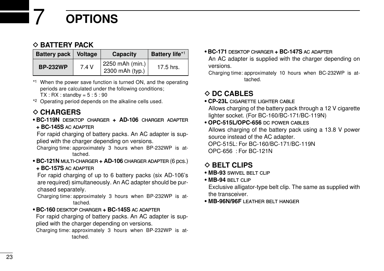
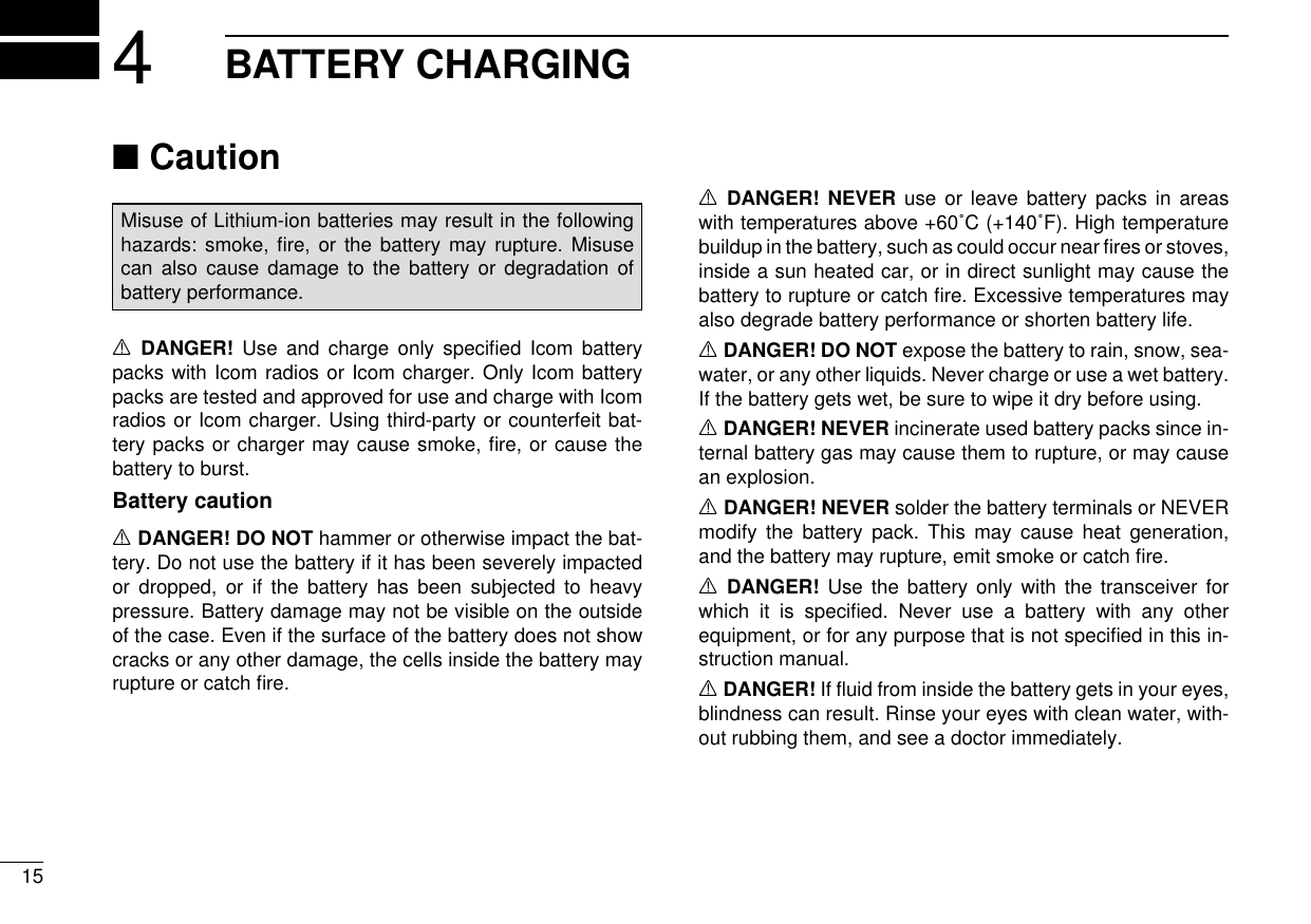
![iiCAUTION: MAKE SURE the flexible antenna, bat-tery pack and jack cover are securely attached to the trans-ceiver, and that the antenna and battery pack are dry before attachment. Exposing the inside of the transceiver to dust or water will result in serious damage to the transceiver.DO NOT operate the transceiver near unshielded electri-cal blast ing caps or in an explosive atmosphere.DO NOT push [PTT] when not actually intending to transmit.DO NOT use or place the transceiver in direct sunlight or in areas with temperatures below –30°C (–22°F) or above +60°C (+140°F).The basic operations, transmission and reception of the transceiver are guaranteed within the specified operating temperature range. However, the LCD display may not be operate correctly, or show an indication in the case of long hours of operation, or after being placed in extremely cold areas.DO NOT modify the transceiver. The transceiver warranty does not cover any problems caused by unauthorized modification.DO NOT use harsh solvents such as benzine or alcohol when cleaning, as they will damage the transceiver surfaces.BE CAREFUL! The transceiver will become hot when operating it continuously for long periods of time.PRECAUTIONSR DANGER! NEVER short the terminals of the battery pack.R DANGER! Use and charge only specified Icom bat-tery packs with Icom radios or Icom chargers. Only Icom bat-tery packs are tested and approved for use with Icom radios or charged with Icom chargers. Using third-party or coun-terfeit battery packs or chargers may cause smoke, fire, or cause the battery to burst.R WARNING! NEVER hold the transceiver so that the antenna is very close to, or touching exposed parts of the body, especially the face or eyes, while transmitting. The transceiver will perform best if the microphone is 5 to 10 cm (2 to 4 inches) away from the lips and the transceiver is verti-cal.R WARNING! NEVER operate the transceiver with a headset or other audio accessories at high volume levels. Hearing experts advise against continuous high volume op-eration. If you experience a ringing in your ears, reduce the volume level or discontinue use.R WARNING! NEVER operate the transceiver while driving a vehicle. Safe driving requires your full attention—anything less may result in an accident.](https://usermanual.wiki/ICOM-orporated/292600.User-Manual/User-Guide-1649351-Page-3.png)
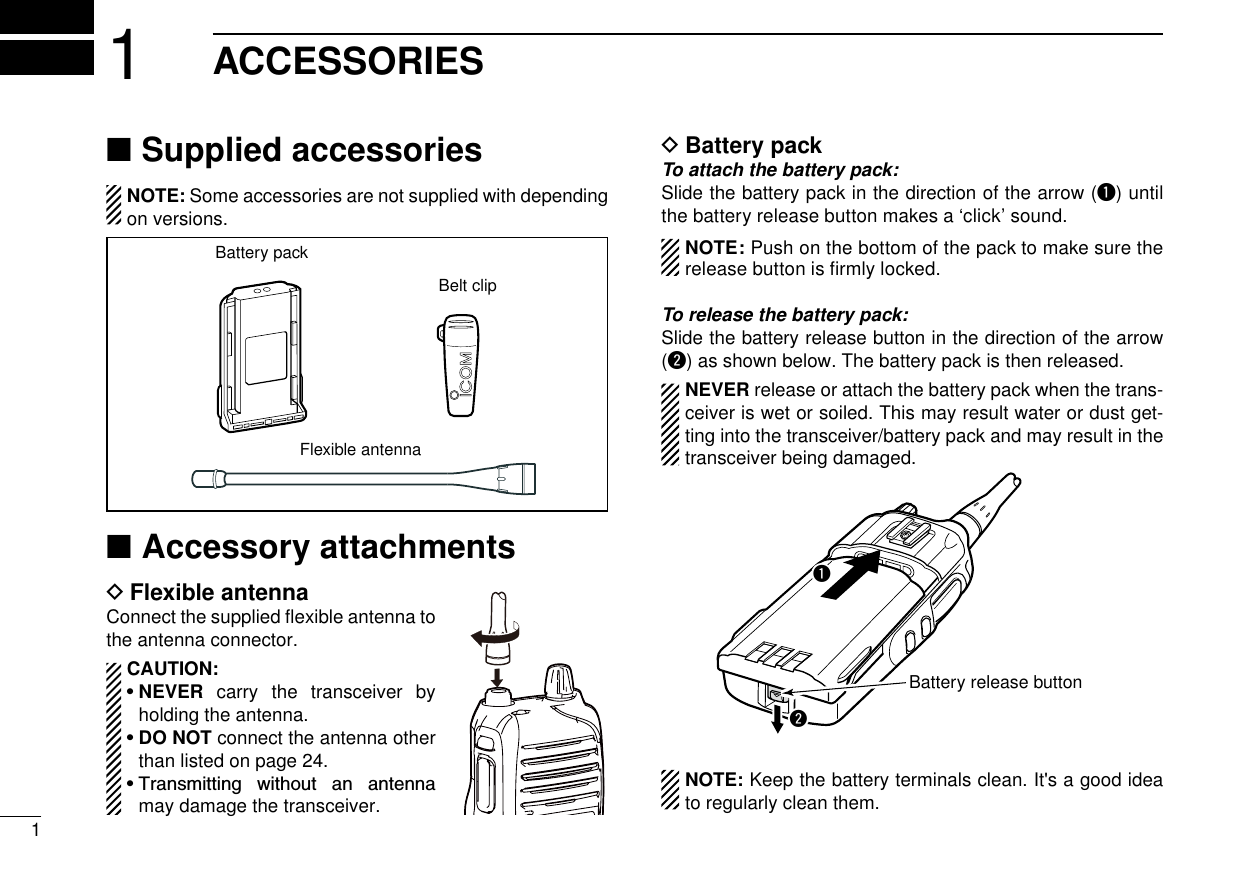
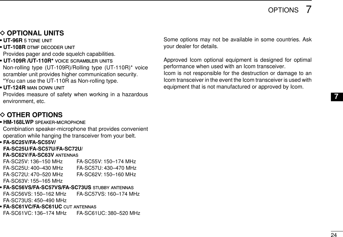
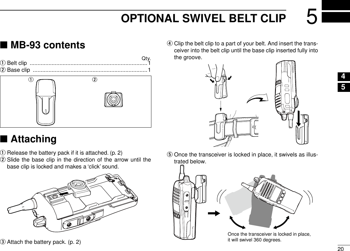
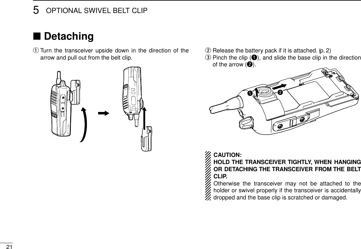
![21ACCESSORIES1Belt clip DTo attach the belt clip:Release the battery pack if it is attached. q w Slide the belt clip in the direction of the arrow until the belt clip is locked and makes a ‘click’ sound.To detach the belt clip: Release the battery pack if it is attached. q Pinch the clip ( wq), and slide the belt clip in the direction of the arrow (w).qwJack cover DTo attach the jack cover:q Attach the jack cover to the [MIC/SP] jack.w Tighten the screws.w[MIC/SP] jackJack coverqqqw CAUTION: • Attach the jack cover when the op-tional speaker-microphone is not used. • Use the supplied screws only.To detach the jack cover:q Unscrew the screws using a phillips screwdriver.w Detach the jack cover for the speak-er-microphone connection.](https://usermanual.wiki/ICOM-orporated/292600.User-Manual/User-Guide-1649351-Page-7.png)
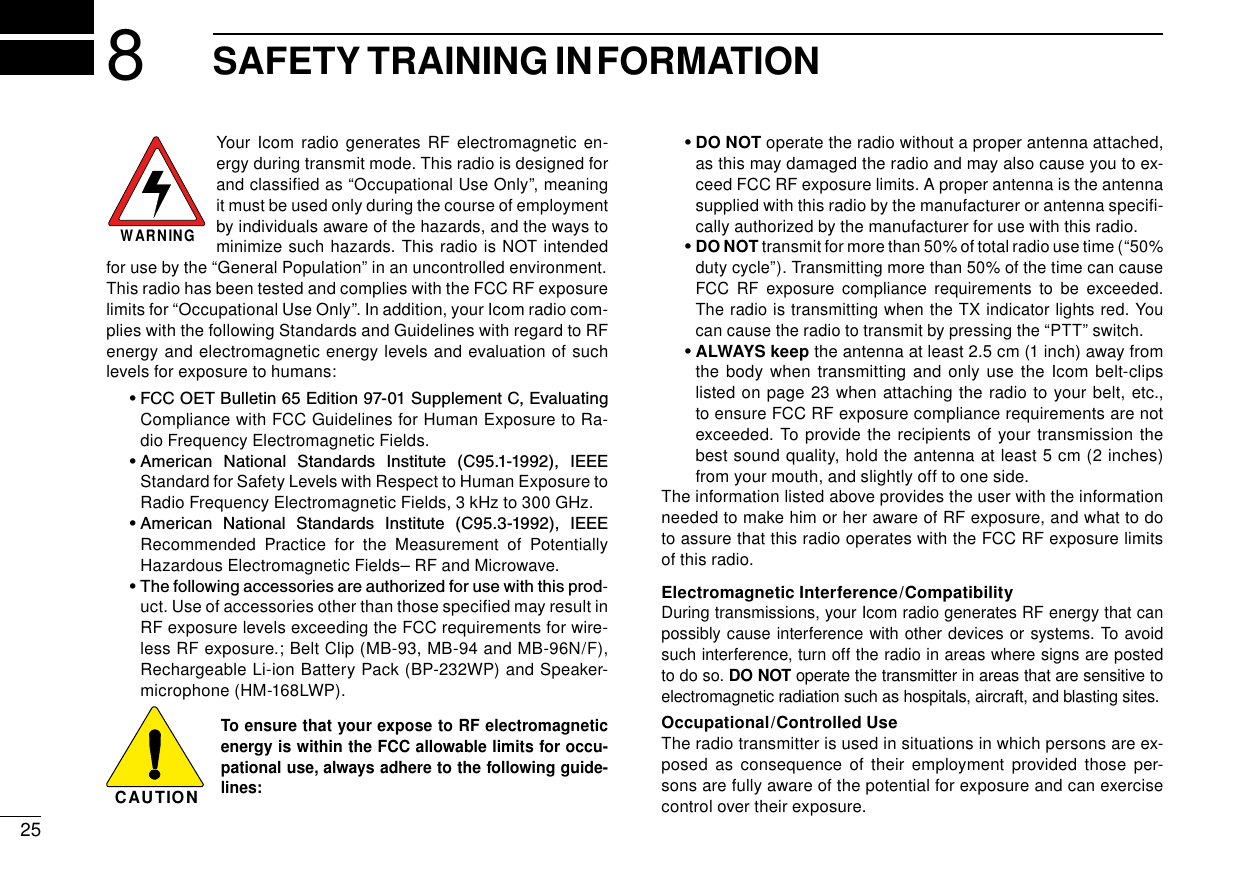
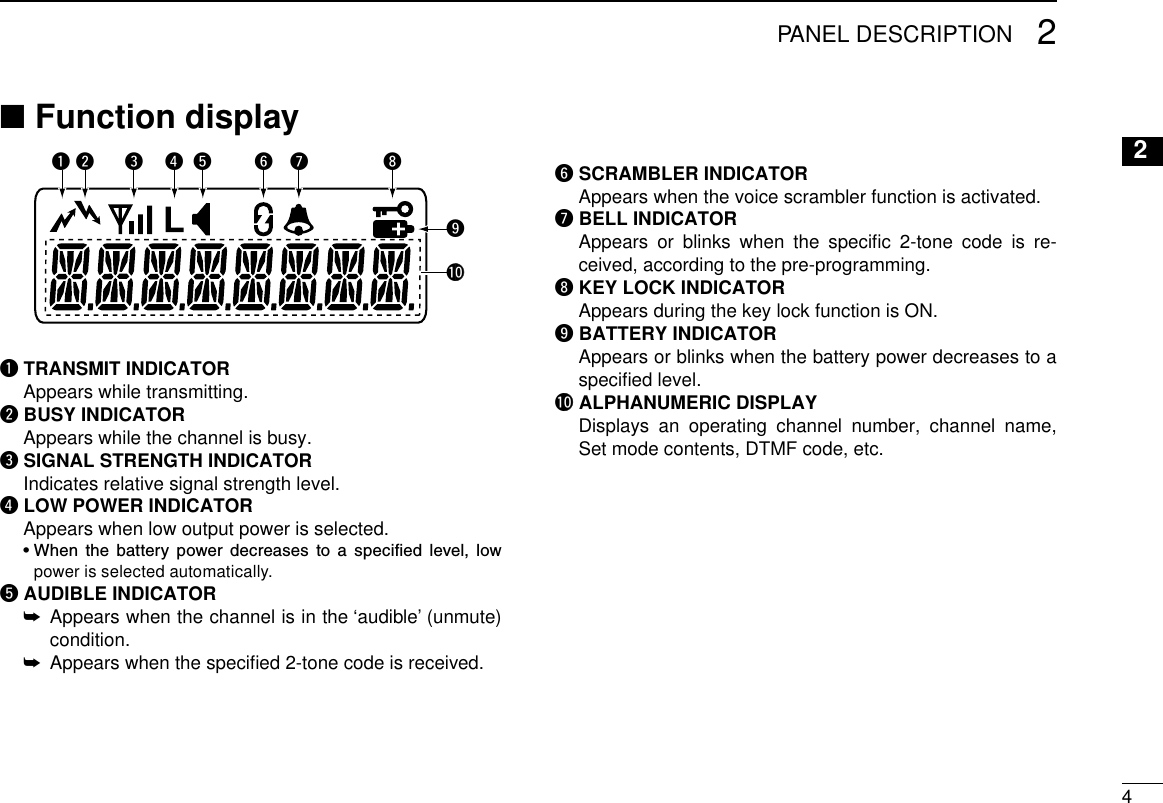
![32PANEL DESCRIPTIONFront panel ■qwreouyMicrophoneSpeakertiq ANTENNA CONNECTORConnects the supplied antenna.w DEALER-PROGRAMMABLE KEY [Emer] Desired function can be programmed by your dealer. (p. 7)e DEALER-PROGRAMMABLE KEY [Side1] Desired function can be programmed by your dealer. (p. 5)r PTT SWITCH [PTT]Push and hold to transmit; release to receive.t DEALER-PROGRAMMABLE KEYS [Side2]/[Side3] Desired functions can be programmed independently by your dealer. (p. 5)y DEALER-PROGRAMMABLE KEYS [P0] to [P3] Desired functions can be programmed independently by your dealer. (p. 5)u FUNCTION DISPLAY (p. 4) Displays a variety of information such as an operating channel number/name, 2-tone code, DTMF numbers, se-lected function and so on.i EXTERNAL MICROPHONE/SPEAKER JACK Connect an optional speaker-microphone. NOTE: Connect or disconnect the optional equipment after the transceiver is turned OFF.Jack coverNOTE: Attach the jack cover when the optional equipment is not used. See (p. 2) for details.o VOLUME CONTROL [VOL] Rotate to turn the power ON/OFF and adjusts the audio level.](https://usermanual.wiki/ICOM-orporated/292600.User-Manual/User-Guide-1649351-Page-8.png)
![52PANEL DESCRIPTIONProgrammable function keys ■The following functions can be assigned to [Emer], [Side1], [Side2], [Side3], [P0], [P1], [P2] and [P3] programmable function keys. Consult your Icom dealer or system operator for details con-cerning your transceivers programming.If the programmable function names are bracketed in the fol-lowing explanations, the specific key is used to activate the function depends on the programming.CH UP AND DOWN KEYS ➥ Push to select an operating channel.➥ Push to select a transmit code channel after pushing [TX Code CH Select].➥ Push to select a DTMF channel after pushing [DTMF Au-todial].➥ Push to select a scan group after pushing and holding [Scan A Start/Stop]/[Scan B Start/Stop] for 1 second.SIREN KEYPush to emit a siren.ZONE KEYPush this key, then push [CH Up] or [CH Down] to select the desired zone.What is “zone”?— The desired channels are assigned into a zone according to the intended use for grouping. For example, ‘Staff A’ and ‘Staff B’ are assigned into a “Business” zone, and ‘John’ and ‘Cindy’ are assigned into a “Private” zone.SCAN A KEY➥ This key’s operation depends on the Power ON Scan set-ting. When the power ON scan function is turned OFF; Push to start and cancel scanning operation. In case of transmission during scan, scanning will be cancelled. When the power ON scan function is turned ON; Push to pause scanning, then resumes scanning after passing a specified time period. In case of transmission during scan, scanning will be cancelled. ➥ Push and hold this key for 1 second to indicate the scan group, then push [CH Up] or [CH Down] to select the de-sired group.SCAN B KEY➥ Push to start and cancel scanning operation. In case of transmission during scan, scanning will be paused. Then resumes scanning after passing a specified time period.➥ Push and hold this key for 1 second to indicate the scan group, then push [CH Up] or [CH Down] to select the de-sired group.PRIO A/B KEYS ➥ Push to select Priority A or Priority B channel.➥ Push and hold [Prio A (Rewrite)] or [Prio B (Rewrite)] for 1 second to reassign the operating channel to Priority A or Priority B channel.](https://usermanual.wiki/ICOM-orporated/292600.User-Manual/User-Guide-1649351-Page-10.png)
![62PANEL DESCRIPTION2SCAN ADD/DEL (TAG) KEY➥ Push to add a channel to, or delete it from the current scan list. • When a channel is added to the current scan list, the display shows “SCAN ON.” When a channel is deleted from the current scan list, the display shows “SCAN OFF.” After showing “SCAN ON” or “SCAN OFF,” the display shows the current scan list text.➥ You can add a channel to, or delete it from the scan list after selecting the list. 1. Hold down for 1 second to display the current scan list, and then push [CH Up] or [CH Down] to select a desired list. 2. Push this key to add a channel to, or delete it from the selected list. 3. Hold down this key for 1 second to exit the scan list selection mode.➥ Push this key while a scan is paused on a channel, except for primary or secondary channel, and then the channel is deleted from the scan list. • Depending on the setting, the deleted channel is added to the scan list again after the scan is cancelled. (Nuisance Delete function)C.TONE CH ENT KEYPush to select the continuous tone channel using [CH Up]/[CH Down] to change the tone frequency/code setting. The selected channel remains set as the continuous tone channel until another channel is designated as such.MR-CH 1/2/3/4 KEYSPush to select memory channels 1 to 4 in the operating zone directly.MONI KEY Mute and release the CTCSS (DTCS) or 2-tone squelch mute. Open any squelch/deactivate any mute while pushing and holding this key.LOCK KEY➥ Push and hold for 1 second to electronically lock all pro-grammable keys except the following: [Call] (incl. Call A and Call B), [Moni], [Emergency], [Sur-veillance], [Siren], [Lone Worker] and [OPT 1/2/3].➥ Push and hold for 1 second again to turn the lock function OFF.HIGH/LOW KEY Push to select the transmit output power temporarily or per-manently, depending on the presetting.• Ask your dealer for the output power level for each selection.OPT MOMENTARY KEYS Controls the output signal level of the optional ports in the optional unit connector while pushing and holding this key.OPT OUT KEYS Push to control the output signal level of the optional ports in the optional unit connector.SCRAMBLER FUNCTIONPush to toggle the voice scrambler function ON and OFF.](https://usermanual.wiki/ICOM-orporated/292600.User-Manual/User-Guide-1649351-Page-11.png)
![72PANEL DESCRIPTIONTALK AROUND KEYPush to turn the talk around function ON and OFF.• The talk around function equalizes the transmit frequency to the receive frequency for transceiver-to-transceiver communication.WIDE/NARROW KEYPush to toggle the IF bandwidth between wide and narrow.DTMF AUTODIAL KEY➥ Push to enter the DTMF channel selection mode. Then se-lect the desired DTMF channel using [CH Up]/[CH Down].➥ After selecting the desired DTMF channel, push this key to transmit the DTMF code.RE-DIAL KEYPush to transmit the last-transmitted DTMF code.CALL KEYS Push to transmit a 2-tone.• Call transmission is necessary before you call another station de-pending on your signaling system.• [Call A] and/or [Call B] may be available when your system em-ploys selective ‘Individual/Group’ calls. Ask your dealer which call is assigned to each key.LONE WORKER KEYPush to turn the Lone Worker function ON or OFF.• If the Lone Worker function is activated, the Emergency function is automatically turned ON after the specified time period has passed with no operation is performed.TX CODE CHANNEL UP/DOWN KEYS Push to select a TX code channel directly.EMERGENCY KEYPush and hold to transmit the emergency call.• The transceiver can transmit the emergency call silently or audibly depending on the presetting. Ask your dealer for details.• When the emergency call transmits with beeps, the emergency text is displayed on the LCD if programmed.• If you want to cancel the emergency call, push and hold the key again before transmitting the call.• The emergency call is transmitted one time only or repeatedly until receiving a control code, depending on the presetting.SURVEILLANCE KEYPush to turn the surveillance function ON or OFF.When this function is turned ON, the beep is not emitted and the LCD backlight does not light when a signal is received or a key is pushed, etc.TX CODE CHANNEL SELECT KEYPush to enter the ID code channel selection mode directly. Then set the desired channel using [CH Up]/[CH Down]. (p. 11)USER SET MODE KEY➥ Push and hold for 1 second to enter user set mode. • During in the user set mode, push this key to select an item that is enabled by your dealer, and change the value or condition by pushing [CH Up] or [CH Down].➥ Push and hold this key for 1 second again to exit user set mode.User set mode is also available via the ‘Power ON function.’ Refer to page 8 also.](https://usermanual.wiki/ICOM-orporated/292600.User-Manual/User-Guide-1649351-Page-12.png)
![83BASIC OPERATION12345678910111213141516Turning power ON ■ Prior to using the transceiver for the first time, the battery pack must be fully charged for optimum life and operation. (p. 17)Rotate [VOL] to turn the power ON. q w If the transceiver is programmed for a start up password, input the digit codes as directed by your dealer. • 10-keypad can be used for password input depending on ver-sion: • The keys in the table below can be used for password input: • The transceiver detects numbers in the same block as identi-cal. Therefore “01234” and “56789” are the same.KEYNUMBER 0549382716[Side3][P0]/[P1]/[P2]/[P3]Side3[VOL] e When the “PASSWORD” indication does not clear after inputting 4 digits, the input code number may be incorrect. Turn the power off and start over in this case.Battery type selection DThe battery type must be selected according to the attaching battery type when turning the transceiver ON.Ask your dealer for details.Turn the power OFF. q While pushing and holding [Emer] and [PTT], turn the wpower ON with rotating [VOL] to toggle the attaching bat-tery type. • After the display appears, release [Emer] and [PTT]. • “DRY BATT” is displayed for about 3 seconds then “L” appears when the battery case operation is selected. In this case, the transmit output power is low. • “LI-ION” is displayed for about 3 seconds when the Lithium-ion battery operation is selected.[VOL][PTT][Emer]Dry battery modeAppears](https://usermanual.wiki/ICOM-orporated/292600.User-Manual/User-Guide-1649351-Page-13.png)
![93BASIC OPERATIONChannel selection ■Several types of channel selections are available. Methods may differ according to your system set up.NON-ZONE TYPE:Push [CH Up] or [CH Down] to select the desired operating channel, in sequence; or, push one of [MR-CH 1] to [MR-CH 4] keys to select a channel directly.ZONE TYPE:Push [Zone], then push [CH Up] or [CH Down] to select the desired zone.AUTOMATIC SCAN TYPE:Channel setting is not necessary for this type. When turn-ing power ON, the transceiver automatically starts scanning. Scanning stops when receiving a call.Call procedure ■When your system employs tone signaling (excluding CTCSS and DTCS), the call procedure may be necessary prior to voice transmission. The tone signaling employed may be a selective calling system which allows you to call specific station(s) only and prevent unwanted stations from contacting you. q Select the desired TX code channel or 2-tone code ac-cording to your System Operator’s instructions. • This may not be necessary depending on programming. • Refer to page 13 for selection. w Push the call key (assigned to one of the dealer program-mable keys: [Emer], [Side1], [Side2], [Side3], [P0], [P1], [P2] and [P3]) or [PTT]. After transmitting a 2-tone code, the remainder of your ecommunication can be carried out in the normal fashion.Selective calling Non-selective calling](https://usermanual.wiki/ICOM-orporated/292600.User-Manual/User-Guide-1649351-Page-14.png)
![103BASIC OPERATION3Receiving and transmitting ■CAUTION: Transmitting without an antenna may damage the transceiver. See page 1 for accessory attachments.Receiving:Rotate [VOL] to turn the power ON. q Push [CH Up] or [CH Down] to select the conventional sys- wtem channel, in sequence. e When receiving a call, adjust the audio output level to a comfortable listening level.NOTE: When a matched RX code signal is received, audio from the microphone is automatically transmitted for a specified time period.** Depending on the presetting. Ask your dealer for details.Transmitting:Wait for the channel to become clear to avoid interference.Push [Call] when initiating a call from your side. q • Coded audio may be heard from the transceiver, then “ ” ap-pears. • This operation may not be necessary depending on your sig-naling system. Ask your dealer for details. While pushing and holding [PTT], speak into the micro- wphone at a normal voice level.Release [PTT] to return to receive. e IMPORTANT: To maximize the readability of your signal; 1. Pause briefly after pushing [PTT]. 2. Hold the microphone 5 to 10 cm (2 to 4 inches) from your mouth, then speak into the microphone at a normal voice level.Transmitting notes D• Transmit inhibit functionThe transceiver has several inhibit functions which restrict transmission under the following conditions: - The channel is in mute condition (‘Inaudible’ condition; “” does not appear.) - The channel is busy. - Un-matched (or matched) CTCSS is received. (Depending on the presetting.) - The selected channel is a ‘receive only’ channel.• Time-out timerAfter continuous transmission for the pre-programmed time period, the time-out timer is activated, causing the transceiv-er to stop transmitting.• Penalty timerOnce the time-out timer is activated, transmission is further inhibited for a period determined by the penalty timer.• PTTID callThe transceiver sends the ID code (DTMF or digital ANI) au-tomatically when [PTT] is pushed (beginning of transmission) and released (end of transmission) depends on the setting.](https://usermanual.wiki/ICOM-orporated/292600.User-Manual/User-Guide-1649351-Page-15.png)
![113BASIC OPERATIONTX code channel selection DIf the transceiver has [TX Code CH Select] assigned to it, the indication can be toggled between the operating channel number (or name) and TX code channel number (or name). When the TX code channel number (or name) is displayed, [CH Up] or [CH Down] selects the TX code channel.USING [TX CODE CH SELECT] KEY: Push [TX Code CH Select]— a TX code channel number q(or name) appears. w Push [CH Up] or [CH Down] to select the desired TX code channel. • Push [TX Code CH Select] again to return to the operating channel number indication. Push [Call] to transmit the selected TX code. eUSING [TX CODE CH UP]/[TX CODE CH DOWN] KEY:If the transceiver has [TX Code CH Up] or [TX Code CH Down] assignment, the programmed TX code channel can be selected directly when pushed.DTMF transmission DIf the transceiver has [DTMF Autodial] assigned to it, the automatic DTMF transmission function is available. Up to 8 DTMF channels are available.TO SELECT A TX CODE:Push [DTMF Autodial]— a DTMF channel appears. q w Push [CH Up] or [CH Down] to select the desired DTMF channel. Push [DTMF Autodial] to transmit the DTMF code in the eselected DTMF channel.](https://usermanual.wiki/ICOM-orporated/292600.User-Manual/User-Guide-1649351-Page-16.png)
![123BASIC OPERATION3User set mode ■User set mode is accessed at power ON and allows you to set seldom-changed settings. In this case you can “custom-ize” the transceiver operation to suit your preferences and operating style.Entering the user set mode: q While pushing and holding [Side2] and [Side3], rotate [VOL] to turn the power ON. Then, push and hold [P0] for 1 second to enter user set mode. w Push [P0] several times to select the appropriate item. Then push [CH Up] or [CH Down] to set the desired level/condition. • Available set mode functions are Backlight, Beep, Beep Level, SQL Level, Mic Gain, Battery Voltage, Signal Moni and Lone Worker. Rotate [VOL] to turn the power OFF to exit user set emode. NOTE: User set mode is also available via a programma-ble function key. Refer to “USER SET MODE KEY.” (p. 7)Emergency Call ■When [Emergency] is pushed for the specified time period*, the emergency signal is transmitted once, or repeatedly, on the specified emergency channel.A repeat emergency signal is automatically transmitted until the transceiver receives an acknowledgement signal, or you turn the transceiver power OFF.When no emergency channel is specified, the signal is transmitted on the previously selected channel.If you want to cancel the emergency call, hold down [Emergency] again before transmitting the call.If your transceiver is programmed for Silent operation, you can trans-mit an Emergency call without the beep sounding and the LED indi-cator lighting.IMPORTANT: It is recommended to set an emergency channel individually to provide the certain emergency call operation.* Depending on the presetting. Ask your dealer for details.D NOTESDepending on the presetting, the following functions are au-tomatically activated. Ask your dealer for details.• Auto TX functionAfter the emergency call transmission, audio from the micro-phone is automatically transmitted for a specified time period.*• Auto RX functionAfter the emergency call transmission, the transceiver stands by in the audible mode for the specified time period.*](https://usermanual.wiki/ICOM-orporated/292600.User-Manual/User-Guide-1649351-Page-17.png)
![133BASIC OPERATIONPriority A channel selection ■Depending on the presetting, the Priority A channel is se-lected each time the transceiver power is turned ON.Man Down Emergency Call ■This function requires the optional UT-124R man down unit.When the transceiver has been left in a horizontal position for the specified time period*, the transceiver enters the emer-gency mode, and then the countdown starts.After the specified time period* has passed, an emergency call is automatically transmitted once, or repeatedly.If the transceiver is placed in a vertical position before the first transmission, the transceiver exits the emergency mode and the emergency call is cancelled.IMPORTANT: It is recommended to set an emergency channel individually to provide the certain emergency call operation.* Depending on the presetting. Ask your dealer for details.Stun function ■When the specified ID, set as a stun ID or kill ID, is received, the stun function is activated.When the stun ID is received, the transceiver becomes unus-able. Entering of the password (p. 8) or receiving a specified ID, set as a revive ID, is necessary to operate the transceiver again in this case.When the kill ID is received, the transceiver switches to the cloning required condition. Cloning the transceiver is neces-sary to operate the transceiver again in this case.Stun function is also available with the MDC 1200 signaling system. (p. 14)Scrambler function ■The voice scrambler function provides private communica-tion between stations. The optional Rolling or Non-rolling type can be available.Push [Scrambler] to turn the scrambler function ON. q • “ ” appears. w Push [Scrambler] again to turn the scrambler function OFF. • “ ” disappears.](https://usermanual.wiki/ICOM-orporated/292600.User-Manual/User-Guide-1649351-Page-18.png)
![143BASIC OPERATION3MDC 1200 system operation ■The MDC 1200 signaling system enhances your transceiv-er’s capabilities. It allows PTT ID*, Emergency signaling, and receiving Radio Check. Also, the dispatcher can stun and re-vive transceivers on the system.* When [PTT] is pushed and/or released, the transceiver transmits your station ID.Transmitting an Emergency Call DThe MDC 1200 system’s Emergency feature can be ac-cessed using the [Emergency] key (p. 7). The transceiver will send an Emergency MDC 1200 system command once, or repeatedly for a programmed number of times until it receives the acknowledgement signal.The emergency call can be transmitted without a beep sound depending on how the emergency function is programmed. Ask your dealer for details.Receiving an Emergency Call DWhen an emergency call is received; q • Beeps sound. • The calling station alias and “EMG EMG” are displayed alter-nately. w Turn power OFF, change the channel, push [PTT] for reply-ing the call, etc. to stop the beep and display indication.Receiving a Stun and Revive DThe dispatcher can send MDC 1200 system signals that will stun or revive your transceiver. If a Stun command is re-ceived that matches your station ID, the transceiver will dis-play “SORRY” (default) and you can not receive or transmit. When a Revive command is received that matches your sta-tion ID, normal operation is restored.](https://usermanual.wiki/ICOM-orporated/292600.User-Manual/User-Guide-1649351-Page-19.png)
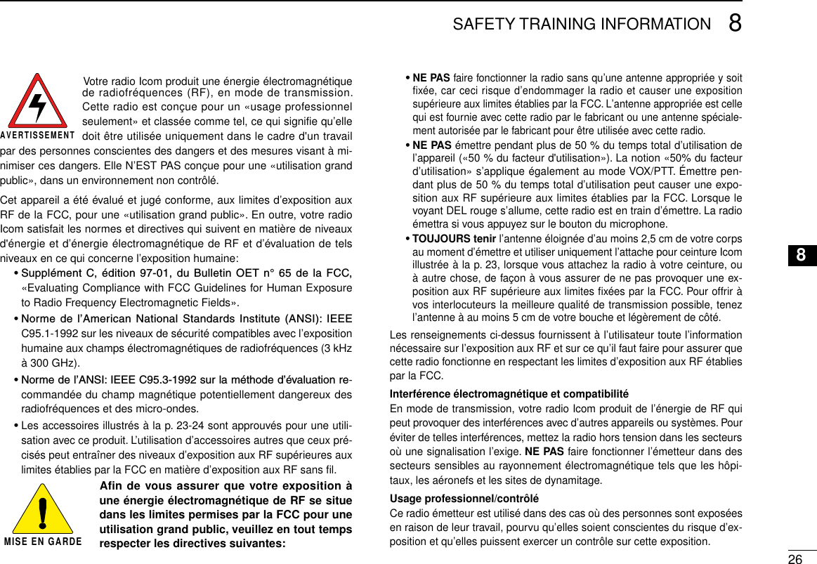
![226SPEAKER MICROPHONE12345678910111213141516Optional HM-168LWP description ■Alligator type clipTo attach the speaker-mic.to your shirt or collar, etc.PTT switchTransmits while pushedReceives while releasedMicrophoneSpeakerTurn the transceiver power OFF when connecting the HM-168LWP.NEVER immerse the connector in water. If the connector becomes wet, be sure to dry it BEFORE attaching it to the transceiver. NOTE: The microphone is located as shown in the dia-gram above. To maximize the readability of your transmit-ted signal (voice), hold the microphone approximately 5 to 10 cm (2 to 4 inches) from your mouth, and speak in a normal voice level.Attachment ■Attach the connector of the speaker-microphone into the [SP MIC] jack on the transceiver and tighten the screws with fin-gers. NOTE: Use only your fingers instead of tools to tighten the screws. IMPORTANT: Keep the [SP MIC] jack cover attached to the transceiver when the speaker-microphone is not in use.Hand tightenCAUTION: Attach the con-nector snugly.A loose connection will al-low water intrusion into the connector.](https://usermanual.wiki/ICOM-orporated/292600.User-Manual/User-Guide-1649351-Page-27.png)