ICOM orporated 297410 VHF Air Band Transceiver User Manual
ICOM Incorporated VHF Air Band Transceiver
UserManual.wiki
>
ICOM orporated
>
297410 User Manual
User Manual
Navigation menu
Upload a User Manual
Namespaces
Wiki Guide
HTML
PDF
Info
Views
User Manual
Discussion / Help
Navigation
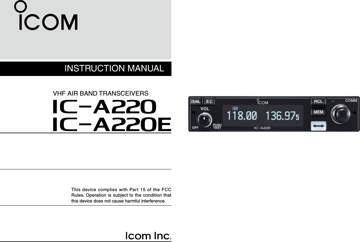
![11PANEL DESCRIPTIONq DUAL SWITCH [DUAL]➥ Push to turn Dualwatch operation ON or OFF. (p. 14)➥ Hold down for two seconds to turn the intercom func-tion ON or OFF.w EMERGENCY CHANNEL SWITCH [EC]➥ Push to set the emergency frequency (121.5 MHz) as the standby frequency. (p. 15)➥ Hold down for two seconds to enter the direct frequency setting mode (p. 6), and set the emergency frequency (121.5 MHz). (p. 15)e VOLUME/POWER SWITCH [VOL]➥ Turn [VOL] to switch the power ON or OFF.➥ Adjusts the audio output level. The volume level bar is displayed while rotating [VOL].➥ Hold down for two seconds to enter the AM squelch level “SQL LEVEL” item in the Settings menu. (p. 6)➥ Push to set the squelch test function ON or OFF. (p. 16)* * When the squelch test function is ON, and the Auto squelch “AUTO SQL” item in the Configuration menu (p. 22) is set to “USER SET,” push [VOL] again to switch the squelch mode. (p. 6)RCLMEMOFFVOLPUSHTESTCOMMDUALECCH09 SAMPLE121.525118.00RX MEMORYeytriouqw ■Front panelCAUTION: DO NOT turn ON power until the en-gines have been started. Otherwise, the power supply circuit may damage.](https://usermanual.wiki/ICOM-orporated/297410/User-Guide-2553003-Page-8.png)
![r FREQUENCY EXCHANGE (FLIP-FLOP) SWITCH [ ]➥ Push to exchange the standby frequency with the ac-tive frequency. (p. 5)➥ Hold down for two seconds to enter the direct frequen-cy setting mode. (p. 6)t MEMORY SWITCH [MEM] Hold down for two seconds to enter a displayed frequency into any blank regular memory channel or delete or revive the selected memory channel (depending on the operating mode). y RECALL SWITCH [RCL]➥ Push to enter and exit the memory mode. (p. 8)➥ Hold down for two seconds to enter the Settings menu. (p. 18)➥ Push to exit the Settings menu. (p. 18)u LIGHT-SENSITIVE DETECTOR This detector senses ambient light. The detector is used to automatically adjust “DISP LOW” or “DISP HIGH” (pp. 23, 24) when the “DISP MODE” (p. 23) is set to ‘AUTO.’i INNER (Small) TUNING DIAL [DIAL]➥ Rotate to set the standby frequencies (kHz digit) (p. 5), memory channels (p. 8), and menu mode settings. (pp. 18, 19)➥ Hold down for two seconds to turn ON the dial/panel lock mode. (p. 15)o OUTER (Large) TUNING DIAL [O-DIAL]Rotate to set the standby frequency (MHz digit) (p. 5), group memory channel (p. 8), select the input digit for group name (p. 10), and so on.Rear panel ■21PANEL DESCRIPTION 01qwe qeFor regular typeOptional MBA-3qweq ANTENNA CONNECTOR Connect the antenna connector.w D-SUB 25 PIN CONNECTOR Connect a 13.8 V or 27.5 V DC power supply, speaker, headset and third party GPS receiver*. Refer to ‘INSTALLATION GUIDE’ for details. *Ask your dealer for available GPS receiver details.](https://usermanual.wiki/ICOM-orporated/297410/User-Guide-2553003-Page-9.png)
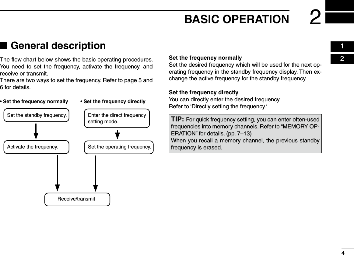
![52BASIC OPERATION ■Receiving and transmittingSetting the standby frequency1. Rotate [DIAL] and [O-DIAL] to select the desired frequency as the standby frequency.• The active frequency is not affected.• Rotate [O-DIAL] to set above 1 MHz digit.• Rotate [DIAL] to set below 100 kHz digit.• You can set the frequency step in the Settings menu. (p. 21)126.405134.80MEMORYExchanging the frequency2. After setting the standby frequency, push [] to exchange it with the active frequency.134.805126.40Receiving3. When receiving a signal, “RX” is displayed and audio is heard.• Rotate [VOL] to adjust the audio level.• Adjust the squelch if necessary. Refer to ‘Squelch settings’ for de-tails.134.805126.40RXTransmitting4. Hold down PTT switch, and then speak at your normal qvoice level. • “TX” is displayed. • DO NOT hold the microphone too closely to your mouth or speak too loudly. This may distort your signal.134.805126.40TXRelease the PTT switch to receive. wNOTE: To prevent interference, listen on the frequency before transmitting. If the frequency is busy, wait until it is clear.NOTE: DO NOT hold down [ ] continuously. Otherwise, the standby frequency disappears. If this happens, again hold down [] until the standby frequency reappears.](https://usermanual.wiki/ICOM-orporated/297410/User-Guide-2553003-Page-12.png)
![62BASIC OPERATION 02You can also directly set the desired frequency. Hold down q[] for two seconds to enter the direct frequen-cy setting mode. • Only the active frequency is displayed.Set an operating frequency. w • Rotate [O-DIAL] to set above 1 MHz digit. • Rotate [DIAL] to set below 100 kHz digit. • You can set the frequency step in the Settings menu. (p. 21) When receiving a signal, “RX” is edisplayed and audio is heard. • Rotate [VOL] to adjust the audio level. • Adjust the squelch if necessary. Refer to ‘Squelch settings’ for details. Hold down PTT switch, and then rspeak at your normal voice level. • “TX” is displayed. • DO NOT hold the microphone too closely to your mouth or speak too loudly. This may distort your signal.Release the PTT switch to receive. t Push y[RCL] or [] to exit the direct frequency setting mode. ■Directly setting the frequency Squelch settings ■Adjusting the squelch DAdjust the squelch to mute undesired noise when no signal received. Hold down q[VOL] for two seconds to enter “SQL LEVEL.” Rotate w[DIAL] to select the desired squelch level to be-tween –10 and 10. Push e[RCL] to exit “SQL LEVEL.”Switching the squelch mode DYou can switch the squelch mode when the Auto squelch “AUTO SQL” item in the Configuration menu (p. 22) is set to “USER SET.” Push q[VOL] to turn ON the squelch test function. • “RX” and “TEST” are displayed. • The squelch mode readout “MN” or “AU” blinks. Push w[VOL] again while the squelch mode readout is blinking to switch the squelch mode. • “RX” and “TEST” disappear and the squelch test function is turned OFF. • MN (manual): Uses the squelch level set in “SQL LEVEL.” • AU (auto): Prevents the audio from breaking up while receiv-ing weak signals.Repeat e q through w to switch the squelch mode again. 121.80121.80RX121.80TX127.005122.00RX MEMORYTESTMN127.005122.00MEMORYAU](https://usermanual.wiki/ICOM-orporated/297410/User-Guide-2553003-Page-13.png)
![73MEMORY OPERATIONGeneral description ■The transceiver has memory to store frequently used fre-quencies. You can easily set the desired frequency by select-ing the channel from the memory.The figure below shows the structure of the memory mode. There are five memory channel types*.* There may be 4 memory types, depending on the transceiver ver-sion.Regular memory channelsCH01:127.00CH02:127.10CH20: 128.575Group memory channelsCH01:120.10CH02:120.20CH10: 130.10Weather memory channels*History memory channelsGPS memory channelsGRP01GRP02GRP05………Memory Memory channel types DRegular memory channels (MEMORY)Up to 20 memory channels can be selected. Group memory channels (GRP01–GRP05)There are up to 50 group channels, with 10 channels in each of 5 groups.Weather memory channels (WEATHER)*10 weather memory channels can be selected.These are used for monitoring NOAA (National Oceanic and Atmospheric Administration) broadcasts.*For only U.S.A. version transceiversHistory memory channels (HISTORY)Up to 20 history memory channels can be selected.The active frequency is automatically written into history memory channels when you push [] to exchange the active and standby frequencies. (except weather memory channels: For only U.S.A. version transceivers.)GPS memory channels (GPS)Up to 10 GPS memory channels can be selected.When connected to an external GPS receiver* equipped with an airport frequency database, you can enter the frequency data at nearby airports into the GPS memory channels.* Ask your dealer for available GPS receiver details.](https://usermanual.wiki/ICOM-orporated/297410/User-Guide-2553003-Page-14.png)
![83MEMORY OPERATION 03Basic operation ■ ■ Editing Regular memory/Group memory channelsMemory mode menu DThere are memory mode menus to edit the memory contents. They contain the following items.REPLACE (p. 9)Enter the selected memory channel frequency to the standby frequency.DELETE (p. 9)Deletes the selected memory channel frequency.REVIVEReturns the selected memory channel to its previous state.CH NAME (For only regular memory channel)Sets the channel name to the selected regular memory chan-nel.GRP NAME (For only group memory channel)Sets the group name to the selected memory group.CH TAG (For only group memory channel)Sets the channel tag to the selected memory channel. (Se-lecting the group memory channel is the only option.)DONEReturns to the memory mode. Push q[RCL] to enter the mem-ory mode. • The memory channel number is displayed. • The memory channel name is also displayed if it has been en-tered. Rotate w[O-DIAL] to select the memory channel types. • For the group memory channel, push [DIAL] and then rotate [O-DIAL] to select a group. Rotate e[DIAL] to select the de-sired channel. Push r[RCL] to change standby frequency to the selected fre-quency and exit the memory mode. • For the group memory channel, push [RCL] twice to change the standby frequency to the selected frequency and exit the memory channel. • Hold down [RCL] for two seconds to exit the memory mode with-out changing the previously set standby frequency. Push t[ ] to exchange to the active frequency.CH01127.005118.00GRP01CH02128.105118.00GRP02128.105118.00118.005128.10CH01127.005118.00MEMORY](https://usermanual.wiki/ICOM-orporated/297410/User-Guide-2553003-Page-15.png)
![93MEMORY OPERATION DClearing the memory contents You can clear unwanted memory channels.Push q[RCL] to enter the memory mode. • The memory channel number is displayed. • The memory channel name is also displayed if it has been en-tered.Rotate w[O-DIAL] to select a desired memory channel. • Select regular memory channels or group memory channels. • For the group memory channels, push [DIAL] and then rotate [O-DIAL] to select a group. Rotate e[DIAL] to select a desired channel. Push r[MEM] and then rotate [O-DIAL] to select “DE-LETE.” • The channel number blinks. • For the group memory channel, push [DIAL], [MEM] and then rotate [O-DIAL] to select “DELETE.”CH01127.000127.000122.00MEMORYÅDELETE Ç Push t[MEM] to clear the memory channel data.CH01122.00MEMORY Push y[RCL] to exit the memory mode. • For the group memory channel, hold down [RCL] for two sec-onds to exit the memory mode. DEnter frequencies into memory channelsTo enter frequencies into memory channels, follow the steps below. Rotate q[DIAL] and [O-DIAL] to set the desired frequency for the standby frequency.Push w[RCL] to enter the memory mode. • The memory channel number is displayed. • The memory channel name is also displayed if it has been en-tered. Rotate e[O-DIAL] to select a desired memory channel. • Select regular memory channels or group memory channels. • For the group memory channel, push [DIAL] and then rotate [O-DIAL] to select a group. Push r[MEM] and then ro-tate [O-DIAL] to select “REPLACE.” • The channel number blinks. • For the group memory channel, push [DIAL], [MEM] and then rotate [O-DIAL] to select “REPLACE.” Rotate t[DIAL] to select a channel to be entered.Push y[MEM] to enter the frequency into the channel. • “WRITE COMPLETED” is displayed when the regular memory channel is entered.Push u[RCL] to exit the memory mode. • For the group memory channel, hold down [RCL] for two sec-onds to exit the memory mode.CH01128.000127.000122.00MEMORYREPLACE ÇCH02128.000127.000122.00MEMORYREPLACE Ç](https://usermanual.wiki/ICOM-orporated/297410/User-Guide-2553003-Page-16.png)
![103MEMORY OPERATION 03 DEntering channel names (For only regular memory channels)The regular memory channels can display a six character name in addition to the memory number. Push q[RCL] to enter the memory mode, and then rotate [O-DIAL] to select the regular memory channel. Rotate w[DIAL] to select a desired channel. Push e[MEM] and then rotate [O-DIAL] to select “CH NAME.”Push r[MEM]. • The channel name’s 1st digit blinks.Rotate t[DIAL] to select a desired character. • Push [DIAL] to switch from upper case letters (A, B, C, ···) → lower case (a, b, c, ···) → number (0, 1, 2, ···) → then again to upper case letters (A, B, C, ···) in sequential order. • You can enter the characters listed below. Rotate y[O-DIAL] to select the next input digit. Repeat u t–y to enter the memory channel name. Push i[MEM] to set the memory channel name. Push o[RCL] to exit the memory mode. DEntering group names (For only group memory channels)The memory groups can display a six character name in ad-dition to the group number (“GRP01”–“GRP05”). Push q[RCL] to enter the memory mode, and then rotate [O-DIAL] to select the group memory channel. Push w[DIAL] and then rotate [O-DIAL] to select a memory group from GRP01 to GRP05. • Push [DIAL] again to set the memory group. Push e[MEM] and then rotate [O-DIAL] to select “GRP NAME.” Push r[MEM]. • The channel name’s 1st digit blinks. Rotate t[DIAL] to select the desired character. • Push [DIAL] to switch from upper case letters (A, B, C, ···) → lower case (a, b, c, ···) → number (0, 1, 2, ···) → then again to upper case letters (A, B, C, ···) in sequential order. • You can enter the characters listed below.Rotate y[O-DIAL] to select the next input digit. Repeat u t–y to input the group name. Push i[MEM] to set the group name. Hold down o[RCL] to exit the memory mode.A B C D E F G H I J K L M N O P Q R S T U V W X Y Z [ \ ] ^ _ `a b c d e f g h i j k l m n o p q r s t u v w x y z { | } ~ (space) ! ” # $ % & ’ ( ) ∗ + , – . /0 1 2 3 4 5 6 7 8 9 : ; < = > ? @ A B C D E F G H I J K L M N O P Q R S T U V W X Y Z [ \ ] ^ _ `a b c d e f g h i j k l m n o p q r s t u v w x y z { | } ~ (space) ! ” # $ % & ’ ( ) ∗ + , – . /0 1 2 3 4 5 6 7 8 9 : ; < = > ? @](https://usermanual.wiki/ICOM-orporated/297410/User-Guide-2553003-Page-17.png)
![113MEMORY OPERATION D Selecting channel tag names (For only group memory channels)The tag name can be set to a three character name, in ad-dition to the group number. It is convenient for separating memory types.q Push [RCL] to enter the memory mode, and then rotate [O-DIAL] to select group memory channel. Push w[DIAL] and then rotate [O-DIAL] to select a memory group from GRP01 to GRP05. • Push [DIAL] again to set the memory group. Push e[MEM] and then rotate [O-DIAL] to select “CH TAG.” Push r[MEM] and then rotate [DIAL] to select the desired channel tag. • The tag name shown to the right is selectable. Push t[MEM] to set the channel tag. Hold down y[RCL] to exit the memory mode.CH01127.005122.00GRP01TWR Channel tag listTAG NAMEDISPLAY MEANSGroup*1GPS*2_ _ _ YES – Non-tagTWR YES YES TowerGND YES YES GroundATS YES YES ATISATF YES YES Air trafficAPP YES YES ApproachARR YES YES ArrivalAWS YES YES Automatic Weather StationCLR YES YES Clearance / DeliveryCTF YES YESCommon Traffic Advisory FrequencyDEP YES YES DepartureFSS YES YES Flight Service StationRFS YES YES Remote Flight Service StationUNI YES YES Unicom frequencyMF YES YES Mandatory frequencyOTH YES – OtherU-1 YES – User1 setting (p. 24)U-2 YES – User2 setting (p. 24)*1Group memory, *2GPS memory About U-1/U-2You can edit U-1 and U-2 to the desired tag name in the Con-figuration menu. Refer to page 24 for the details.](https://usermanual.wiki/ICOM-orporated/297410/User-Guide-2553003-Page-18.png)
![123MEMORY OPERATION 03 Selecting a ■weather memory channelThe U.S.A. version transceivers have built-in VHF marine WX (weather) channels. Push q[RCL] to enter the memory mode. Rotate w[O-DIAL] to select “WEATHER.” Rotate e[DIAL] to set a desired weather memory channel. Push r[RCL] to exit the memory mode.WX01162.555122.00DUAL WEATHER• Weather memory channel listChannel Frequency Channel FrequencyWX01 162.550 MHz WX06 162.500 MHzWX02 162.400 MHz WX07 162.525 MHzWX03 162.475 MHz WX08 161.650 MHzWX04 162.425 MHz WX09 161.775 MHzWX05 162.450 MHz WX10 163.275 MHz (For only U.S.A. version transceivers) ■History memory channelThe transceiver has 20 history memory channels.When pushing [], the standby frequency is stored into a history memory channel.The frequencies are stored into the history memory channel from “CH01” to “CH20.” Push q[RCL] to enter the memory mode.Rotate w[O-DIAL] to select “HISTORY.” Rotate e[DIAL] to set a desired history memory channel. Push r[RCL] to exit the memory mode.CH01127.005122.00HISTORY](https://usermanual.wiki/ICOM-orporated/297410/User-Guide-2553003-Page-19.png)
![133MEMORY OPERATION■ Selecting a GPS memory channelWhen connected to an external GPS receiver* with an airport frequency database, you can transfer frequency data such as nearby airports to the GPS memory (maximum 10 memory channels).*Ask your dealer for available GPS receiver details.Push q[RCL] to enter the memory mode. Rotate w[O-DIAL] to select “GPS.” Rotate e[DIAL] to set a desired GPS memory channel. r Push [RCL] to exit the memory mode.CH01 TWR122.055122.00GPS RJTJAirport codeTag nameNOTE: Refer to the GPS receiver’s instruction manual for transferring the frequency data.Editing GPS memory ■The received GPS memory data is stored in the desired group memory channel.Push q[RCL] to enter the memory mode. Rotate w[O-DIAL] to select “GPS.” • “GPS” is displayed. Push e[MEM] to enter the GPS memory channel edit mode, then rotate [O-DIAL] to select a desired group memory. • “GPS” and airport code blink. Push r[MEM] to store the GPS memory channel data to the selected group memory. Push t[RCL] to exit the memory mode. ■Protecting memoryThe transceiver has memory protection which inhibits the ed-iting (storing, deleting, replacing, and so on) of the regular memory and group memory.Refer to ‘Memory Protection’ (p. 22) for details.NOTE: The GPS memory data is overwritten if the se-lected GPS memory channel already contains other data.](https://usermanual.wiki/ICOM-orporated/297410/User-Guide-2553003-Page-20.png)
![144OTHER FUNCTIONS 03 04 ■Dualwatch operationThe Dualwatch operation monitors the active frequency at certain intervals, even when receiving a signal on the standby frequency. When a signal is received on the active frequency, the transceiver switches to the active frequency and stays on it until the signal disappears, irrespective of the standby frequency status. Push q[DUAL] to enter Dualwatch operation. • “DUAL” is displayed on the active frequency display. • The active or standby frequency’s “RX” blinks when receiving a signal, or the squelch opens.Push w[DUAL] again to exit Dualwatch operation. • “DUAL” disappears. ■Priority watchThe Priority watch operation monitors the active frequency at certain intervals* even when receiving a signal on the standby frequency. When a signal is received on the active frequency and standby at the same time, the transceiver pref-erentially receives the active frequency and stops receiving the standby frequency. * You can set the priority watch intervals in the Configuration menu. Refer to page 22 for details.ATTENTION! During Dualwatch operation, the standby frequency’s audio may be interrupted during the monitoring interval, but this is not a malfunction.129.405121.00RX DUAL RX](https://usermanual.wiki/ICOM-orporated/297410/User-Guide-2553003-Page-21.png)
![154OTHER FUNCTIONSUsing the ■lock functionThe lock function prevents accidental frequency changes and accidental function activation. There are two lock modes, panel lock and dial lock. You can select the lock mode in the Settings menu. Refer to page 20 for details.Panel lock: Lock transceiver’s keys and dials except [EC] and [VOL].Dial lock: Lock [DIAL] and [O-DIAL]. Hold down q[DIAL] for two seconds to turn ON the lock function. • “OFD” is displayed when dial lock mode is selected. • “OFP” is displayed when panel lock mode is selected.w Push [DIAL] to turn OFF the lock function. • “OFD” or “OFP” disappears. Accessing the 121.5 MHz ■emergency frequencyThe transceiver can be set to the 121.5 MHz emergency fre-quency immediately. This function can be activated even if the key lock function is in use. Hold down q[EC] for two seconds to set the emergency fre-quency (121.50 MHz) in direct frequency setting mode. • “EC” is displayed.121.505EC Hold down w[ ] to return to the normal frequency display mode, and then push [] to exchange emergency fre-quency with the standby frequency. • Set the frequency other than 121.500 MHz before pushing [ ] to the standby frequency if necessary. • “EC” disappears. NOTE: LOCK RELEASE FUNCTIONThis transceiver has a lock release function that releases the Lock function when an operator gets into a panic.The lock function is released when pushing any keys (ex-cept [EC]) eight times, or rotate any dial (except [VOL]) 25 clicks in five seconds.You can also set the 121.5 MHz emergency frequency from normal frequency display mode. Push q[EC] to set the emergency frequency to the stand-by frequency.Push w[] to change to the active frequency. • “EC” is displayed.121.50 118.00EC](https://usermanual.wiki/ICOM-orporated/297410/User-Guide-2553003-Page-22.png)
![164OTHER FUNCTIONS 04Enabling the ■intercomWhen two headsets are connected to the transceiver, you can use them as a voice-activated intercom. While holding down q[DUAL], rotate [VOL] to turn ON the transceiver’s power. • Conguration menu is displayed. Rotate w[O-DIAL] to select “INCOM MODE.” Rotate e[DIAL] to set the intercom usable setting to ON. Push r[RCL] to exit the Configuration menu and restart the transceiver. Hold down t[DUAL] for two seconds to enable the intercom function. • “ICS” is displayed. • You can set the headphone output level in the Settings menu. (p. 20) • You can also set microphone 1 and microphone 2 audio input levels in the Settings menu. (p. 20)Opening the ■squelch for testThis function manually opens the squelch for testing.Push q[VOL] to turn ON the squelch test function. • “RX” and “TEST” are displayed. To turn the function OFF, push w[VOL] again. • “RX” and “TEST” disappear.Setting the ■frequency stepYou can select Frequency steps of 8.33 kHz or 25 kHz in the menu mode. Hold down q[RCL] for two seconds to enter the Settings menu. Rotate w[O-DIAL] to select “FREQ. STEP.” Rotate e[DIAL] to select the desired frequency steps of 8.33 kHz or 25 kHz. Push r[RCL] to exit the Settings menu.Using the ■remote controlYou can remotely control the frequency exchange switch, in-tercom, and recall switch by connecting pins 1, 3, and 17* of the D-Sub 25 pin connector on the rear panel to the switches connected to the power ground.Refer to “INSTALLATION GUIDE” for details.• Turn the remote control in the Conguration menu ON. Refer to page 25 for details. * Connect pins L, 10, and 15 to the switches connected to the power ground if you are using the optional MBA-3 connector.](https://usermanual.wiki/ICOM-orporated/297410/User-Guide-2553003-Page-23.png)
![174OTHER FUNCTIONSScanning automatically searches for weather channel sig-nals.Repeatedly scans all weather memory channels. You can set the interval time (scan speed) for the scan in the Settings menu. Refer to page 22 for details. Push q[RCL] to enter the memory mode, and then rotate [O-DIAL] to select the weather memory channel. Hold down w[VOL] for two seconds to start a weather mem-ory channel scan. • “SEARCH“ blinks while scanning. • To change the scan direction, turn [DIAL]. • The scan continues even when receiving a signal on the active frequency.162.555122.00RX WEATHERSEARCH When receiving a signal on the weather channel: e • “RX” blinks on the standby frequency display and the scan is cancelled. • “DUAL” is displayed on the active frequency display.WEATHER161.655122.00RX DUAL RXWX08When no signal is received on the weather channel: r • “NO WTH” is displayed even searches “WX01” to “WX10” chan-nels for three times and the scan is cancelled. Hold down t[VOL] for two seconds to cancel the scan man-ually. (For only U.S.A. version transceivers) Scanning the ■weather memory channels](https://usermanual.wiki/ICOM-orporated/297410/User-Guide-2553003-Page-24.png)
![185MENU MODE 04 05Using the menu mode ■The menu mode is accessible at power ON and allows you to set seldom-changed settings. You can customize the trans-ceiver settings to suit your preferences and operating style.There are two types of menu mode, Settings menu and Con-figuration menu. Using the DSettings menu Rotate q[VOL] to turn ON the transceiver’s power. • Push [RCL] to exit memory mode if the memory mode is se-lected. Hold down w[RCL] for two seconds to enter the Settings menu. Rotate e[O-DIAL] to select setting items. Rotate r[DIAL] to select a desired setting. Push t[RCL] to exit the Settings menu.SETTINGSSQL LEVEL -01001/44RCLMEMOFFVOLPUSHTESTCOMMDUALEC-010-009009010Desired settingFM SQL LVHP LEVELINCOM LV1SQL LEVELSettings itemsSettings menu items Items numberSetting value• Settings menu itemsItem Ref. Item Ref.SQL LEVEL p. 20MIC1 GAINp. 21SQL MODE p. 20MIC2 GAINp. 21FM SQL LV p. 20 SIDETONE LV p. 21HP LEVEL p. 20 DISP MAN. p. 21INCOM LV1 p. 20 FREQ DISP p. 21INCOM LV2 p. 20 AUX LEVEL p. 21ANL p. 20 BEEP p. 21LOCK MODEp. 20 FREQ. STEP p. 21](https://usermanual.wiki/ICOM-orporated/297410/User-Guide-2553003-Page-25.png)
![195MENU MODE Using the DConguration menu While holding down q[DUAL], rotate [VOL] to turn ON the transceiver’s power. • Conguration menu is displayed. Rotate w[O-DIAL] to select a setting item. Rotate e[DIAL] to select a desired setting. Push r[RCL] to exit the Configuration menu and restart the transceiver.CONFIG RCL=SAV/EXMIC1 SQL 00209/44RCLMEMOFFVOLPUSHTESTCOMMDUALECOFF001029030Desired settingMIC1 SQLMIC2 SQLDW INTERVALAUTO SQLConfiguration itemsConfiguration menu itemsItems numberSetting value• Conguration menu itemsItem Ref. Item Ref.AUTO SQL p. 22DISP HIGHp. 24SQL SW p. 22DISP RESP.p. 24MIC1 SQL p. 22U-1 ID SETp. 24MIC2 SQL p. 22 U-2 ID SET p. 24DW INTERVAL p. 22 AUX IN p. 24PRI. WATCH p. 22 AUX MAX LEVEL p. 24PW INTERVAL p. 22 INCOM MODE p. 24MEM PROTECT p. 22 TIME OUT p. 25GRP MEMORY p. 23 INTERLOCK p. 25TX MIC SEL p. 23 INTLOCK MODE p. 25DISP MODE p. 23 REM SWAP p. 25DISP AUTO p. 23 REM INCOM p. 25DISP EXT p. 23 REM RECALL p. 25DISP LOWp. 23 MEM CLEAR p. 25](https://usermanual.wiki/ICOM-orporated/297410/User-Guide-2553003-Page-26.png)
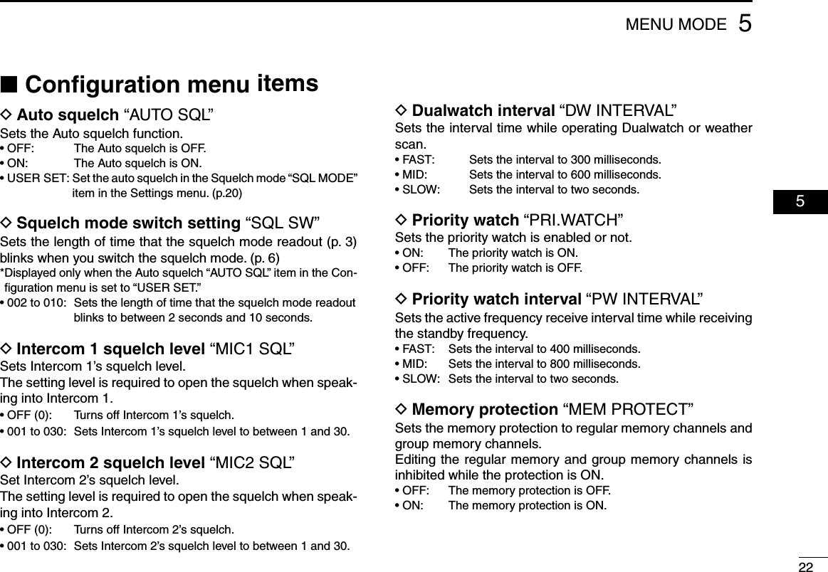
![205MENU MODE 05 ■Settings menu items DAM squelch level “SQL LEVEL”Adjust the squelch level for AM mode operation.In order to receive signals properly, the squelch must be ad-justed to the proper level.• –010 to 010: Sets the AM squelch level to between –10 and 10. DSquelch mode “SQL MODE”Sets the squelch mode for AM mode operation*.* Displayed only when the Auto squelch “AUTO SQL” item in the Con-figuration menu (p. 22) is set to “USER SET.”• MN (manual): Use “SQL LEVEL” to set the squelch level.• AU (auto): Prevents the audio from breaking up while receiving weak signals. DFM squelch level “FM SQL LV” (For only U.S.A. version transceivers)Set the squelch level for FM mode operation.• –010 to 010: Sets the FM squelch level to between –10 and 10. DHeadphone level “HP LEVEL”Sets the headphone output level while receiving.• AF gain: The output level is the same as [VOL].• OFF (0): Mutes the headphone.• 001 to 080: Sets the audio level to between 1 and 80. DIntercom 1 microphone audio input level “IN-COM LV1”Sets the intercom 1 microphone input level.• OFF (0): Mutes the intercom1 microphone.• 001 to 080: Sets the intercom1 input level to between 1 and 80. DIntercom 2 microphone audio Input level “IN-COM LV2”Sets the intercom 2 microphone input level.• OFF (0): Mutes the intercom 2 microphone.• 001 to 080: Sets the intercom 2 input level to between 1 and 80. DAutomatic noise limiter “ANL”The ANL (Automatic Noise Limiter) function reduces noise components while receiving, such as those caused by engine ignition systems.• OFF: ANL function is OFF.• ON: ANL function is ON. DLock mode “LOCK MODE”Sets the lock function.• OFF : The lock function is OFF.• DIAL: The lock function applies to [DIAL].• PANEL: The lock function applies to switches on the front pan-el.](https://usermanual.wiki/ICOM-orporated/297410/User-Guide-2553003-Page-27.png)
![215MENU MODE DSetting microphone 1 Gain “MIC1 GAIN”Sets microphone 1’s gain.• –010 to 010: Sets the microphone 1’s gain to between –10 and 10. DSetting microphone 2 Gain “MIC2 GAIN”Sets microphone 2’s gain.• –010 to 010: Sets the microphone 2’s gain to between –10 and 10. DSidetone level “SIDETONE LV”When using an optional headset (user supplied) through an adapter, the transceiver sends your transmitted voice to the headset for monitoring.*Ask your dealer in details.• OFF (0): The sidetone function is OFF.• 001 to 080: Sets the sidetone level to between 1 and 80. DManual dimmer control “DISP MAN.”Sets the brightness manually to suit your own preferences.• 000 to 100: Sets the dimmer level to between 0 (OFF) and 100. DFrequency display “FREQ DISP”Sets the 1 kHz digit frequency displaying on the OLED.• OFF : The 1 kHz digit is not displayed on the OLED.• ON : The 1 kHz digit is always displayed on the OLED.• ZERO SUPP.: The 1 kHz digit is displayed only when the 1 kHz digit frequency is 5 kHz. DExternal input level “AUX LEVEL”Sets the external input level.• OFF (0): The external input is disabled.• 001 to 080: Sets the external input level to between 1 and 80.• AF GAIN: Interlocked with [VOL]. DBeep tone level “BEEP”Confirmation beep tones normally sound when storing mem-ory, operating the time-out-timer function, and so on. These can be set at a desired beep level.• OFF (0): The beep tone is OFF.• 001 to 100: Sets the beep tone level to between 1 and 100.NOTE: When using an external speaker, the beep tone level while the squelch is closed is fixed and cannot be changed in the Settings menu. DFrequency step “FREQ. STEP”Sets the desired frequency step: 8.33 kHz or 25 kHz*.• 25kHz: Sets the frequency step to 25 kHz.• 8.33kHz: Sets the frequency step to 8.33 kHz.](https://usermanual.wiki/ICOM-orporated/297410/User-Guide-2553003-Page-28.png)
![245MENU MODE 05D Dimmer brightness (High) “DISP HIGH”Sets the maximum brightness level in the automatic adjust-ment range.** Displayed only when the Dimmer mode “DISP MODE” item in the Configuration menu is set to “AUTO.”• 050 to 100: Sets the maximum dimmer brightness level to be-tween 50 and 100. DDimmer response “DISP RESP.”Sets the dimmer switching speed when selecting “AUTO” in the Dimmer mode “DISP MODE” item. (p. 23)• STANDARD: Selects the normal switching speed.• FAST: Selects the fast switching speed.D USER-1 setting/USER-2 setting “U-1 ID SET”/“U-2 ID SET”You can edit U-1 and U-2 channel tags (p.11) to the desired tag name.q Push [MEM] to enter the U-1 or U-2 tag edit mode.w Rotate [DIAL] to select a desired character.e Rotate [O-DIAL] to select the next input digit.r Repeat the steps w–e to input the desired tag name. • You can set three characters for the tag name.t Push [MEM] again to store the name, and exit the edit mode. DExternal input “AUX IN”Set the audio usage input from an external audio device.Refer to ‘INSTALLATION GUIDE’ for an external audio device connection details.• OFF: The external audio is not used.• ON: The external audio is output from the connected head-set while no signal is received.• INCOM: The external audio is output from the intercom 2’s headset when: - The intercom function is OFF. - While the intercom function is not in use. - While an audio signal is not input into the intercom 1’s microphone.D External input gain “AUX MAX LVL”Sets the maximum gain for audio usage input.* Displayed only when the External input “AUX IN” item in the Configu-ration menu is set to “ON.”• 0 dB: The maximum gain for audio usage input is 0dB.• +3 dB: The maximum gain for audio usage input is +3dB.• +6 dB: The maximum gain for audio usage input is +6dB. DIntercom usable setting “INCOM MODE” Sets the intercom using or not.• ON: The intercom is usable.• OFF: The intercom is unusable.](https://usermanual.wiki/ICOM-orporated/297410/User-Guide-2553003-Page-31.png)
![255MENU MODED Time-Out-Timer “TIME OUT”To prevent accidental prolonged transmission, the transceiver has a time-out-timer.The function inhibits continuous trans-missions longer than the set time period.• 020 to 240: Setting time-out-timer period from 20 seconds to 240 seconds in 10 second steps.D Interlock “INTERLOCK”If the transceiver is connected together with the other trans-ceiver, the interlock function can prevent the transceiver from receiving or transmitting while the other transceiver is trans-mitting.• ON: The interlock function is ON.• OFF: The interlock function is OFF.D Interlock mode “INTLOCK MODE”Sets the desired function to be disabled by the interlock.* Displayed only when the Interlock “INTLOCK” item in the Configura-tion menu is set to “ON.”• TX INHIBIT: Transmission is disabled.• RX MUTE: Audio output is disabled.• BOTH: Both transmission and audio output are disabled.NOTE: The interlock mode is not displayed when the “TX/RX INTERLOCK SW” item is set to “DISABLE.”Ask your dealer for the “TX/RX INTERLOCK SW” setting details.D Remote exchange “REM SWAP”Sets the remote control (p. 16) to use the frequency exchange switch or not.• OFF: The remote control for the frequency exchange switch is OFF.• ON: The remote control for the frequency exchange switch is ON.D Remote incom “REM INCOM”Sets the remote control (p. 16) to use the intercom or not.• OFF: The remote control for the intercom is OFF.• ON: The remote control for the intercom is ON.D Remote recall “REM RECALL”Sets the remote control (p. 16) to use the recall switch or not.• OFF: The remote control for the recall switch is OFF.• ON: The remote control for the recall switch is ON.D Memory clear “MEM CLEAR”Select a desired item to be reset.After the selection, hold down [MEM] for two seconds to reset the selected item’s contents.• MENU: Reset the menu mode items setting to their defaults.• MEMORY: Clear the stored memories except the weather memo-ry channel.• ALL: Reset the menu mode items setting to their defaults and clear the stored memories.](https://usermanual.wiki/ICOM-orporated/297410/User-Guide-2553003-Page-32.png)