ICOM orporated 298001 UHF Mobile Transceiver User Manual Manual
ICOM Incorporated UHF Mobile Transceiver Manual
UserManual.wiki
>
ICOM orporated
>
298001 User Manual
Manual
Navigation menu
Upload a User Manual
Namespaces
Wiki Guide
HTML
PDF
Info
Views
User Manual
Discussion / Help
Navigation
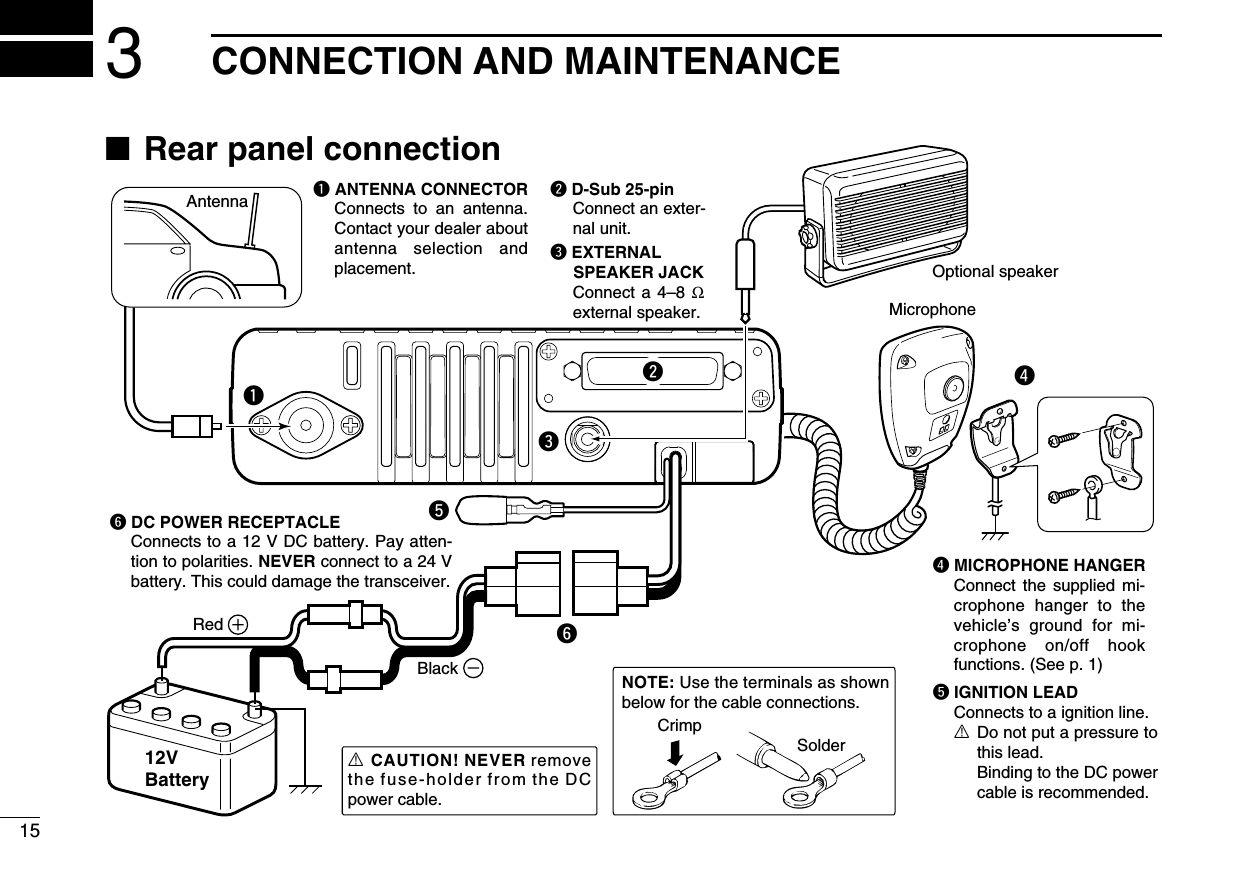
![11PANEL DESCRIPTIONIcom Inc.qeySpeakerFunction display (p. 2)w rt■Front panelqAF VOLUME CONTROL KNOB [VOL]Rotate the knob to adjust the audio output level.• Minimum audio level is pre-programmed.wLED INDICATOR➥Lights red while transmitting a signal.➥Lights green while receiving a signal.eUP/DOWN KEYS [CH Up]/[CH Down]Push to select an operating channel, etc.*The desired function can be assigned by your dealer. (p. 3)rPOWER SWITCH [ ]Push to turn the power ON and OFF.• Automatic scan start, Password prompt and Set mode accessare available at power ON.tDEALER-PROGRAMMABLE KEYSDesired functions can be programmed independently byyour dealer. (p. 3)yMICROPHONE CONNECTORConnect the supplied or optional microphone.NEVER connect non-specified microphones. The pinassignments may be different and the transceiver maybe damaged.DDMICROPHONEThe supplied microphone has a PTT switch and a hanger hook.• The following functions are available when the microphone is on oroff hook (depending on the setting):- Automatic scan start when on hook.- Scan is cancelled when off hook.- Scan is paused when off hook.- Automatic priority channel selection is available when off hook.- Sets to ‘Inaudible’ condition (mute condition) when on hook.- Sets to ‘Audible’ condition (unmute condition) when off hook.](https://usermanual.wiki/ICOM-orporated/298001/User-Guide-770917-Page-4.png)
![21PANEL DESCRIPTION12345678910111213141516■Function displayqSIGNAL STRENGTH INDICATORIndicates relative signal strength level as below.wLOW POWER INDICATORAppears when low output power is selected.eAUDIBLE INDICATOR➥Appears when the channel is in the ‘audible’ (unmute)condition.➥Appears when the specified 2/5-tone/BIIS*1/MDC*2code is received.rCOMPANDER INDICATORAppears when the compander function is activated.tSCRAMBLER INDICATORAppears when the voice scrambler function is activated.yBELL INDICATORAppears/blinks when the specific 2/5-tone/BIIS*1/MDC*2code is received, according to the pre-programming.uCALL CODE MEMORY INDICATOR➥Appears when the call code memory is selected.➥Appears when a phone call is received.*3iSCROLL INDICATORAppears when the received SDM includes more than 12characters.*1oSDM INDICATORAppears when an SDM is received, or a transmit SDM isselected.*1!0 ALPHANUMERIC DISPLAY➥Displays an operating channel number, channel name,Set mode contents, DTMF code, etc. ➥The indication mode can be selected from 1 line or 2lines. Ask your dealer for details.• In this instruction manual, the LCD illustration is describedusing the 2 lines indication mode.!1 ACTIVATED KEY INDICATORAppears above the key assigned as [Scan A Start/Stop],[Scan B Start/Stop], [Scan Add/Del(Tag)], [Lock], [TalkAround], [Surveillance], [Talkgroup]*4and [Digital]*1keysduring that key is activated.*1BIIS operation only *2MDC operation only*3LTR®operation only *4Digital operation onlySee the operating guide for details of BIIS, MDC and LTR®system operations. Ask your dealer for details.Weak ⇐ Receive Signal level ⇒ Strong Icom Inc.qw ertyuio!0!1](https://usermanual.wiki/ICOM-orporated/298001/User-Guide-770917-Page-5.png)
![31PANEL DESCRIPTION■Programmable function keysThe following functions can be assigned to [UP], [DOWN],[P0], [P1], [P2], [P3] and [P4] programmable function keys.Consult your Icom dealer or system operator for details con-cerning your transceivers programming.If the programmable function names are bracketed in the fol-lowing explanations, the specific key is used to activate thefunction depends on the programming.CH UP AND DOWN KEYS ➥Push to select an operating channel.➥Push to select a transmit code channel after pushing [TXCode CH Select].➥Push to select a DTMF channel after pushing [DTMFAutodial].➥Push to select a scan group after pushing and holding[Scan A Start/Stop]/[Scan B Start/Stop] for 1 sec.ZONE KEYPush this key, then select the desired zone using [CH Up]/[CH Down].What is “zone”?—The desired channels are assignedinto a zone according to the intended use for grouping.For example, ‘Staff A’ and ‘Staff B’ are assigned into a“Business” zone, and ‘John’ and ‘Cindy’ are assigned into a“Private” zone.SCAN A START/STOP KEY➥This key’s operation depends on the Power ON Scan setting.When the power ON scan function is turned OFF;Push to start and cancel scanning operation.When the power ON scan function is turned ON;Push to pause scanning, then resumes scanning after aspecified time period has passed.➥Push and hold this key for 1 sec. to indicate the scan group,then select the desired group using [CH Up]/[CH Down].SCAN B START/STOP KEY➥Push to start and cancel scanning operation. Scanresumes after a specified time period has passed whenscan is cancelled except for this key.➥Push and hold this key for 1 sec. to indicate the scan group,then select the desired group using [CH Up]/[CH Down].SCAN ADD/DEL (TAG) KEY➥Push to add or delete the selected channel to/from thescan group.1. Push to indicate the scan group, then push [CH Up] or [CHDown] to select the desired group.2. Push to add or delete the channel to/from the selected scangroup.3. Push and hold for 1 sec. to exit the scan group selection mode.➥Push this key while scan is paused (a signal is detected)on a channel (except for priority channel,) the channel iscleared from the scan group.Depending on the setting, the cleared channel is addedto the scan group again after the scan is cancelled.](https://usermanual.wiki/ICOM-orporated/298001/User-Guide-770917-Page-6.png)
![41PANEL DESCRIPTION1PRIO A/B KEYS➥Push to select Priority A or Priority B channel.➥Push and hold [Prio A (Rewrite)] or [Prio B (Rewrite)] to setthe operating channel as the Priority A or Priority B chan-nel.MR-CH 1/2/3/4 KEYSPush to select the memory channel 1 to 4 directly.MONI (AUDI) KEY➥Mute and release the CTCSS (DTCS) or 2-tone squelchmute. Open any squelch/deactivate any mute while push-ing and holding this key. (LMR operation only)➥Activates one of (or two of) the following functions on eachchannel independently: (PMR or BIIS PMR operation only)• Push and hold to un-mute the channel (audio is emitted;‘Audible’ condition).• Push to mute the channel (sets to ‘Inaudible’ only).• Push to un-mute the channel (sets to ‘Audible’ only).• Push after the communication is finished to send a ‘reset code’.(BIIS PMR operation only)NOTE: The un-mute condition (‘Audible’ condition) mayautomatically return to the mute condition (‘Inaudible’ con-dition) after a specified period depending on programming.PUBLIC ADDRESS KEYPush to activate the Public Address (PA) function for voiceamplification. When the PA function is activated, the audiooutput can be controlled from the transceiver separately withthe [VOL] control knob.• This function is available when the external unit, such as a audioamplifier, speaker, etc. is additionally connected.•Push this key, then speak into the microphone while pushing andholding [PTT].•[CH Up]/[CH Down] also allow you to set the audio output level.RX SPEAKER KEYThe received audio can be heard via the external speakerwhen this key is pushed.• This function is available when the external speaker is additionallyconnected.•This function is useful when you are out of the vehicle.•The audio output level is linked to the transceiver’s volume control.LIGHT KEYPush to turn the transceiver’s backlight ON for about 5 sec.when the backlight function is turned OFF in user set mode.LOCK KEYPush and hold to electronically lock all programmable keysexcept the following:[Moni(Audi)], [Light], [Lock], [Call] (incl. Call A and Call B),[Emergency Single]/[Emergency Repeat] (incl. Silent), [Surveillance]and [OPT 1/2/3].](https://usermanual.wiki/ICOM-orporated/298001/User-Guide-770917-Page-7.png)
![51PANEL DESCRIPTIONHIGH/LOW KEYPush to select the transmit output power temporarily or per-manently, depending on the pre-setting.•Ask your dealer for the output power level for each selection.C.TONE CH ENT KEYPush to select the continuous tone channel using [CH Up]/[CHDown] to change the tone frequency/code setting after push-ing this key. The selected channel remains set as the continu-ous tone channel until another channel is designated as such.TALK AROUND KEYPush to turn the talk around function ON and OFF.•The talk around function equalizes the transmit frequency to thereceive frequency for transceiver-to-transceiver communication.WIDE/NARROW KEYPush to toggle the IF bandwidth between wide and narrow.• The wide passband width can be selected from 25.0 or 20.0 kHzusing the CS-F5060 CLONING SOFTWARE. (PMR or BIIS PMR opera-tion only) Ask your dealer for details.DTMF AUTODIAL KEYPush to enter the DTMF channel selection mode. Then selectthe desired DTMF channel using [CH Up]/[CH Down].After selecting the DTMF channel, push again to transmit theselected DTMF code.RE-DIAL KEYPush to transmit the last-transmitted DTMF code.• TX memories are cleared after turning the transceiver OFF.SCRAMBLER FUNCTIONPush to toggle the voice scrambler function ON and OFF.CALL KEYSPush to transmit a 2/5-tone/BIIS ID code.•Call transmission is necessary before calling another stationdepending on your signalling system.•[Call A] and/or [Call B] may be available when your system employsselective ‘Individual/Group’ calls. Ask your dealer which call isassigned to each key.EMERGENCY KEYS➥Push and hold to transmit an emergency call.➥When [Emergency Single (Silent)] or [Emergency Repeat(Silent)] is pushed, an emergency call is transmitted withno beep emission and LCD indication change.• If you want to cancel the emergency call, push (or push andhold) the key again before transmitting the call.• The emergency call is transmitted one time only or repeatedlyuntil receiving a control code depending on the pre-setting.SURVEILLANCE KEYPush to turn the surveillance function ON or OFF.When this function is turned ON, the beep is not emitted andthe LCD backlight and the LED indicator do not light when asignal is received or a key is pushed.COMPANDER KEYPush to toggle the compander function ON and OFF. The compander function reduces noise components from thetransmitted audio to provide clear communication.](https://usermanual.wiki/ICOM-orporated/298001/User-Guide-770917-Page-8.png)
![61PANEL DESCRIPTION1TX CODE ENTER KEY (PMR or BIIS PMR operation only)Push to enter the ID code edit mode directly, for both 5-toneand MSK. Then set the desired digit using [CH Up]/[CH Down]. (p. 11)TX CODE CHANNEL SELECT KEY➥Push to enter the ID code channel selection mode directly.Then set the desired channel using [CH Up]/[CH Down]. (p. 10)➥During ID code channel selection mode, push for 1 sec. toenter the ID code edit mode for 5-tone and MSK. Then setthe desired digit using [CH Up]/[CH Down]. (p. 11)TX CODE CHANNEL UP/DOWN KEYS➥Push to select a TX code channel directly.➥Push to set the desired digit during the ID code edit mode.ID-MR SELECT KEY (PMR or BIIS PMR operation only)➥Recalls detected ID codes.• Push this key, then select the ID code using [CH Up]/[CH Down].• Up to 5 ID’s are memorized.➥Push and hold for 1 sec. to erase the selected ID’s.HOOK SCAN KEYWhen the on hook scan function is activated, push this keyto disables on hook scan function (stop scanning) temporari-ly. Push this key again to re-start scanning.USER SET MODE KEY➥Push and hold to enter user set mode.• During user set mode, push this key to select an item, andchange the value or condition using push [CH Up]/[CH Down].➥Push and hold this key again to exit user set mode.User set mode is also available via the ‘Power ON function.’Refer to p. 14 also.MR-CH ENT KEYSPush to enter the memory channel selection mode, then enterthe desired channel number using the 10-keypad of the con-nected microphone.OPT 1/2/3 KEYSPush to control the output signal level from the optional unitconnector.](https://usermanual.wiki/ICOM-orporated/298001/User-Guide-770917-Page-9.png)
![71PANEL DESCRIPTIONDFor Digital mode operation onlyTALKGROUP KEYPush to enter the talkgroup ID code selection mode. Thenselect the desired talkgroup ID code using [CH Up]/[CHDown]. (p. 12)TX STATUS KEYPush to enter the Status message selection mode. Thenselect the desired Status message using [CH Up]/[CH Down].(p. 12)TONE/RAN CH SELECT KEY➥While in the analog mode operation, push to select thecontinuous tone channel using [CH Up] or [CH Down] tochange the tone frequency/code setting.➥While in the digital mode operation, push to select the RANchannel using [CH Up] or [CH Down] to change the RANcode setting.➥While in the mixed (digital and analog) mode operation,push to select the continuous tone channel using [CH Up]or [CH Down] to change the tone frequency/code setting.Then push this key to enter the setting. After that, the RANchannel selection screen appears. Select the RAN channelusing [CH Up] or [CH Down] to change the RAN code set-ting. Then push this key to enter the setting.](https://usermanual.wiki/ICOM-orporated/298001/User-Guide-770917-Page-10.png)
![82BASIC OPERATION12345678910111213141516■Turning power ONqPush []to turn the power ON.wIf the transceiver is programmed for a start up password,input the digit codes as directed by your dealer.• The keys as below can be used for password input:The transceiver detects numbers in the same block as identical.Therefore “01234” and “56789” are the same.eWhen the “PASSWORD” indication does not clear afterinputting 6 digits, the input code number may be incorrect.Turn the power off and start over in this case.■Channel selectionSeveral types of channel selections are available. Methodsmay differ according to your system set up.NON-ZONE TYPE:Push [CH Up] or [CH Down] to select the desired operatingchannel, in sequence; or, push one of [MR-CH 1] to [MR-CH4] keys to select a channel directly.ZONE TYPE:Push [Zone] then push [CH Up] or [CH Down] to select thedesired zone.AUTOMATIC SCAN TYPE:Channel setting is not necessary for this type. When turningpower ON, the transceiver automatically starts scanning.Scanning stops when receiving a call.KEYNUMBER 0549382716](https://usermanual.wiki/ICOM-orporated/298001/User-Guide-770917-Page-11.png)
![92BASIC OPERATION■Call procedureWhen your system employs tone signaling (excluding CTCSSand DTCS), the call procedure may be necessary prior to voicetransmission. The tone signalling employed may be a selec-tive calling system which allows you to call specific station(s)only and prevent unwanted stations from contacting you.qSelect the desired TX code channel, 2/5-tone code orTalkgroup ID code* according to your System Operator’sinstructions.• This may not be necessary depending on programming.• Refer to pgs. 10–12 for selection.*Digital mode operation only.wPush the call key (assigned to one of the dealer program-mable keys; except for the Digital mode operation) or [PTT].eAfter transmitting, the remainder of your communicationcan be carried out in the normal fashion.■Receiving and transmittingReceiving:qPush [ ] to turn the power ON.wPush [CH Up] or [CH Down] to select a channel, insequence.eWhen receiving a call, adjust the audio output level to acomfortable listening level.Transmitting:Wait for the channel to become clear to avoid interference.qTake the microphone off hook.• 2/5-tone mute may be released. (The ‘audible’ condition isselected and BUSY indicator lights green.)• A priority channel may be selected automatically.wWait for the channel to become clear.• The channel is busy when BUSY indicator lights green.ePush [CALL] when initiating a call from your side.• Coded audio may be heard from the transceiver, then “ ”appears.• This operation may not be necessary depending on your signal-ing system. Ask your dealer for details.rWhile pushing and holding [PTT], speak into the micro-phone at your normal voice level.tRelease [PTT] to receive.IMPORTANT: To maximize the readability of your signal;1. Pause briefly after pushing [PTT].2. Hold the microphone 5 to 10 cm (2 to 4 inches) fromyour mouth, then speak into the microphone at a normalvoice level.Selective calling Non-selective calling](https://usermanual.wiki/ICOM-orporated/298001/User-Guide-770917-Page-12.png)
![102BASIC OPERATION12345678910111213141516DTransmitting notes• Transmit inhibit functionThe transceiver has several inhibit functions which restricttransmission under the following conditions:- The channel is in mute condition (‘Inaudible’ condition; “ ” does not appear.)- The channel is busy.- Un-matched (or matched) CTCSS is received.(Depending on the pre-setting)- Un-matched (or matched) RAN is received.*(Depending on the pre-setting)- The selected channel is a ‘receive only’ channel.*Digital mode operation only.• Time-out timerAfter continuous transmission for the pre-programmed timeperiod, the time-out timer is activated, causing the transceiv-er to stop transmitting.• Penalty timerOnce the time-out timer is activated, transmission is furtherinhibited for a period determined by the penalty timer.DTX code channel selectionIf the transceiver has [TX Code CH Select] assigned to it, theindication can be toggled between the operating channelnumber (or name) and TX code channel number (or name).When the TX code channel number (or name) is displayed,[CH Up]/[CH Down] selects the TX code channel.USING [TX CODE CH SELECT] KEY:qPush [TX Code CH Select]— a TX code channel number(or name) appears.wPush [CH Up] or [CH Down] to select the desired TX codechannel.ePush [Call] to transmit the selected TX code.USING [TX CODE CH UP]/[TX CODE CH DOWN] KEY:If the transceiver has a [TX Code CH Up] or [TX Code CHDown] key assignment, the programmed TX code channelcan be selected directly when pushed.NOTE for PMR or BIIS PMR operation:• The LCD indication does not change when the operatingchannel number (or name) is displayed.• To check the selected TX code, push [TX Code CHSelect].](https://usermanual.wiki/ICOM-orporated/298001/User-Guide-770917-Page-13.png)
![112BASIC OPERATIONDTX code number edit(PMR or BIIS PMR operation only)If the transceiver has [TX Code CH Select] or [TX CodeEnter] assigned to it, TX code contents can be edited withinthe allowable digits.USING [TX CODE CH SELECT] KEY:qPush [TX Code CH Select] to enter the TX code channelselection mode.• Select the desired channel before entering the TX code channelselection mode if necessary.wPush [TX Code CH Select] for 1 sec. to enter the TX codeedit mode.ePush [TX Code CH Select] to select the desired digit to beedited.• The digit to be edited blinks.rPush [CH Up] or [CH Down] to set the desired digit.tPush [TX Code CH Select] to set the digit. The digit to theright will blink automatically.yRepeat rand tto input all allowable digits.uPush [Call] to transmit the edited TX code.USING [TX CODE ENTER] KEY:qAfter pushing [TX Code CH Select], push [CH Up] or [CHDown], or push [TX Code CH Up] or [TX Code CH Down]to select the desired TX code channel.wPush [TX Code Enter] to enter the TX code edit mode.• The digit to be edited blinks.ePush [TX Code Enter] to select the desired digit to be edit-ed.rPush [CH Up] or [CH Down] to set the desired digit.tPush [TX Code Enter] to set the digit. The digit to the rightwill blink automatically.yRepeat rand tto input all allowable digits.uPush [Call] to transmit the edited TX code.](https://usermanual.wiki/ICOM-orporated/298001/User-Guide-770917-Page-14.png)
![122BASIC OPERATION2DTalkgroup ID code selection(Digital mode operation only)If the transceiver has [Talkgroup] assigned to it, the indicationcan be toggled between the operating channel name (and thechannel number)* and the Talkgroup ID name (or ID code ifthe ID name is not programmed.) When the Talkgroup IDname (or ID code) is displayed, [CH Up] or [CH Down] selectsthe desired Talkgroup ID name (or ID code).qPush [Talkgroup]— Talkgroup ID name (or ID code)appears.wPush [CH Up] or [CH Down] to select the desiredTalkgroup ID name (or ID code).ePush [PTT] to transmit the selected Talkgroup ID.DTX Status message selection(Digital mode operation only)If the transceiver has [TX Status] assigned to it, the indicationcan be toggled between the operating channel name (and thechannel number)* and the Status message (and the Statuschannel.)* When the Status message (and the Status chan-nel)* is displayed, [CH Up] or [CH Down] selects the desiredStatus message.qPush [TX Status]— Status message (and Status channel)*appears.wPush [CH Up] or [CH Down] to select the desired Statusmessage.ePush [PTT] to transmit the selected Status message.* Only when the 2 lines indication mode is selected.STATUS 01TX Status 01When the 2 lines indication mode is selected.Status messageStatus channelTGID01When the 2 lines indication mode is selectedand [Talkgroup] is assigned to [P0].Talkgroup ID nameAppears above the key that [Talkgroup] is assinged after pushed.](https://usermanual.wiki/ICOM-orporated/298001/User-Guide-770917-Page-15.png)
![132BASIC OPERATIONDDTMF transmissionIf the transceiver has [DTMF Autodial] assigned to it, the auto-matic DTMF transmission function is available. Up to 8 DTMFchannels are available.qPush [DTMF Autodial]— a DTMF channel appears.wPush [CH Up] or [CH Down] to select the desired DTMFchannel.ePush [DTMF Autodial] to transmit the DTMF code in theselected DTMF channel.■Scrambler functionThe voice scrambler function provides private communicationbetween stations. The frequency inversion type is equippedto all versions, moreover, the optional Rolling or Non-rollingtype can be available.qPush [Scrambler] to turn the scrambler function ON.• “ ” appears.wPush [Scrambler] again to turn the scrambler functionOFF.• “ ” disappears.](https://usermanual.wiki/ICOM-orporated/298001/User-Guide-770917-Page-16.png)
![142BASIC OPERATION2■User set modeUser set mode is accessed with [User Set Mode] and allowsyou to set seldom-changed settings. In this case you can“customize” the transceiver operation to suit your preferencesand operating style.Entering the user set mode:qWhile pushing and holding [P1] and [P2], push [ ] to turnthe power ON. Then, push and hold [P0] for 1 sec. to enteruser set mode.• You should hold [P1] and [P2] until “SET MODE” appears.wPush [P0] several times to select the appropriate item.Then, push [Up] or [Down] to set the desired level/condi-tion.• Available set mode functions are Backlight, LCD Contrast,Beep, Beep Level, Ringer Level, SQL Level, AF Min Level,Mic Gain, Horn and Signal Moni.ePush and hold [ ] for 1 sec. to turn power OFF, then ONagain to exit set mode.User set mode is also available via a programmable key.Please refer to p. 6 [User Set Mode] section.[ ][P0] [Up]/[Down][P1][P0] [P2] [ ]](https://usermanual.wiki/ICOM-orporated/298001/User-Guide-770917-Page-17.png)