ICOM orporated 298700 VHF Marine Transceiver User Manual
ICOM Incorporated VHF Marine Transceiver Users Manual
UserManual.wiki
>
ICOM orporated
>
298700 User Manual
Users Manual
Navigation menu
Upload a User Manual
Namespaces
Wiki Guide
HTML
PDF
Info
Views
User Manual
Discussion / Help
Navigation
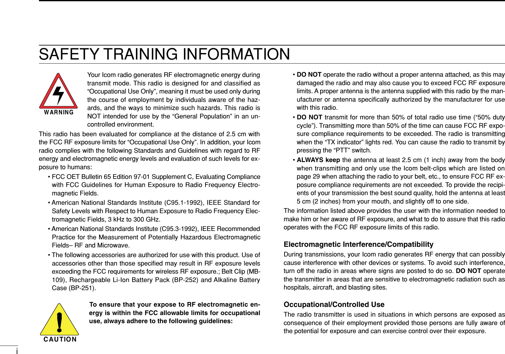
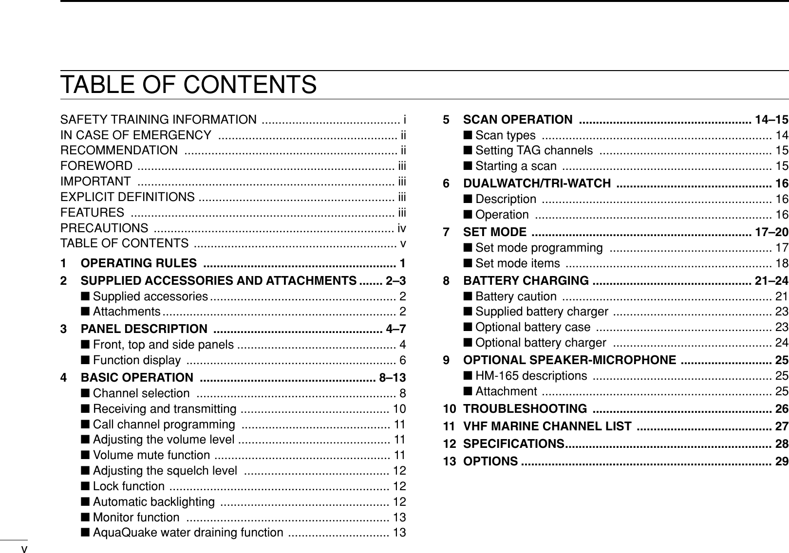
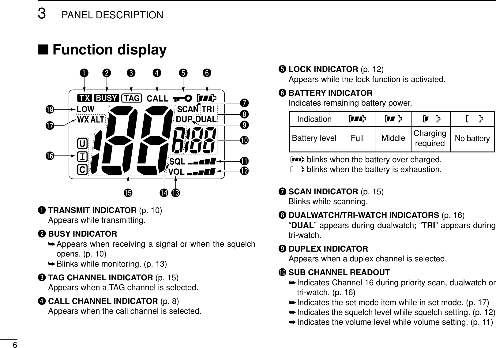
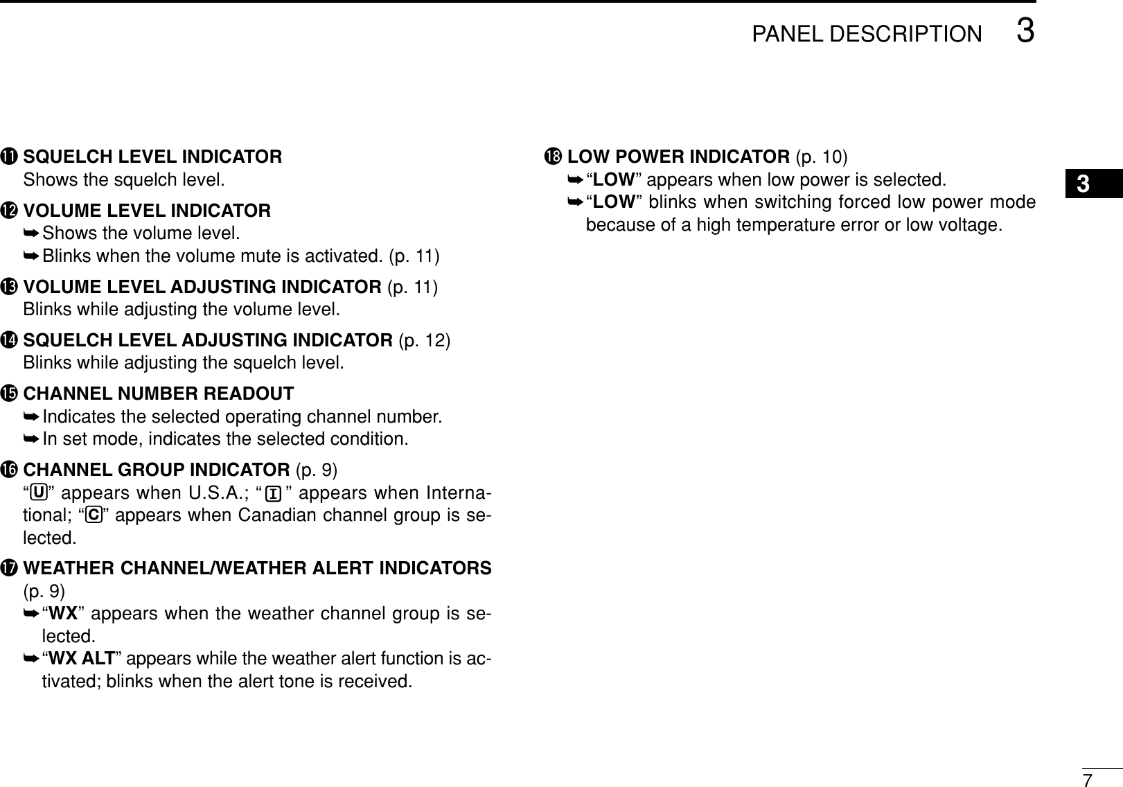
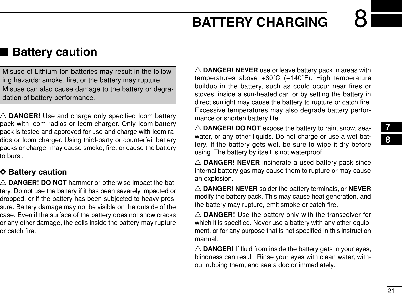
![4PANEL DESCRIPTION3■Front, top and side panelsqPOWER SWITCH [PWR]Push and hold to turn power ON and OFF.wSPEAKER-MICROPHONE CONNECTOR [SP MIC] (p. 25)Connects the optional external speaker-microphone.NOTE: Attach the [SP MIC] cap when the optionalspeaker-microphone is not used. Otherwise, water willget into the transceiver.eANTENNA CONNECTOR (p. 2)Connects the supplied antenna.rCHANNEL/WEATHER CHANNEL KEY [CH/WX•U/I/C]➥Toggles the regular channels and weather channel whenpushed. (p. 9)➥Selects the U.S.A., International or Canadian channelgroup when pushed and held for 1 sec. (p. 9)➥Push to return to the condition before selecting thechannel 16 or the call channel.q Attach the [SP MIC] cap.w Then rotate it clockwise completely.wqMicrophone Function display (pgs. 6, 7)Speakero!2!1!0ityurwqe](https://usermanual.wiki/ICOM-orporated/298700/User-Guide-735497-Page-10.png)
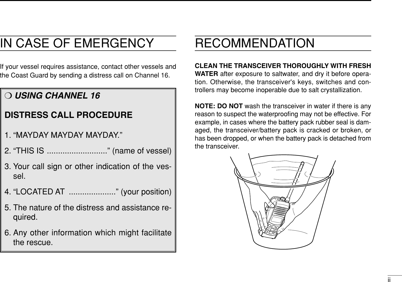
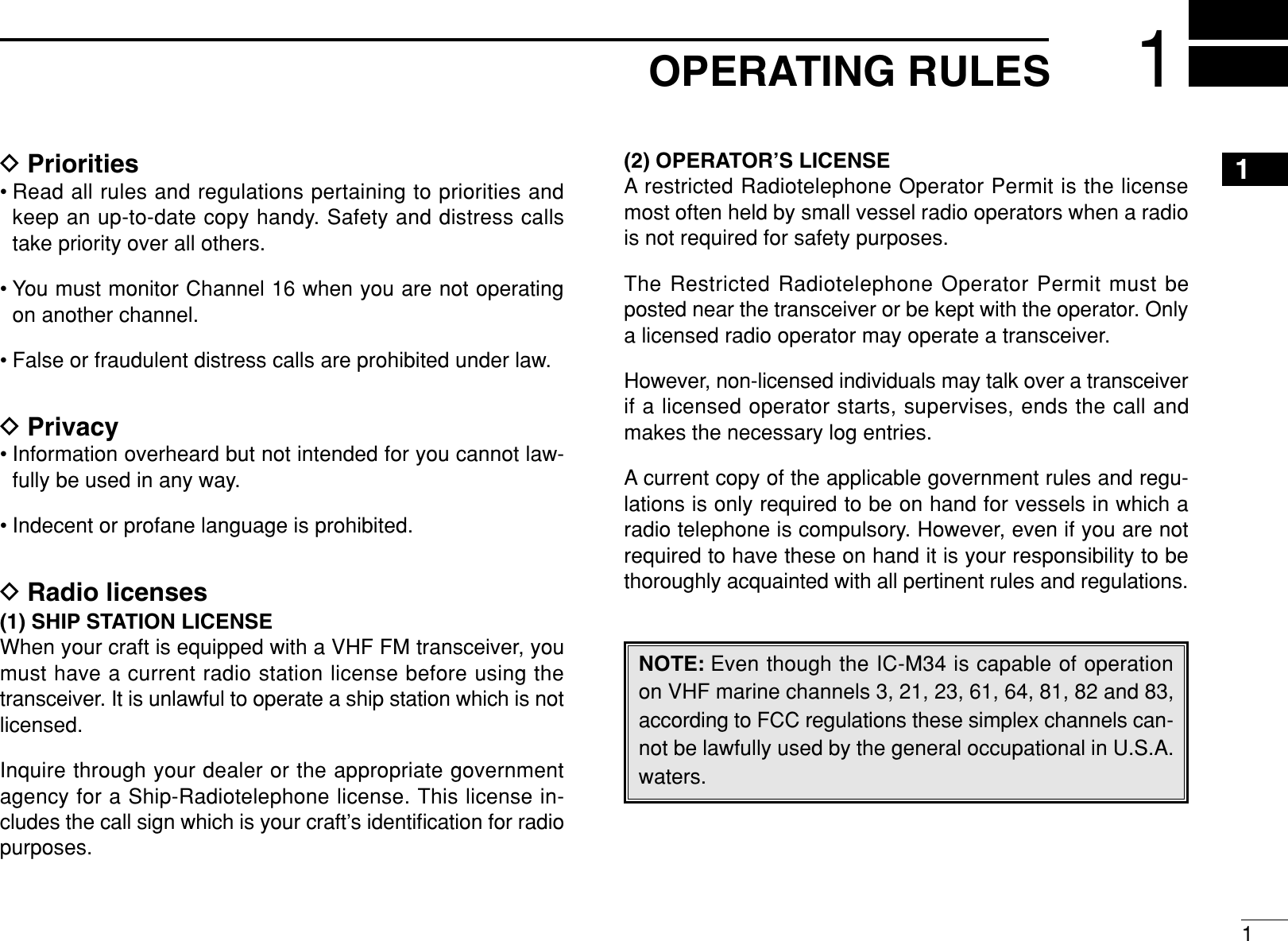
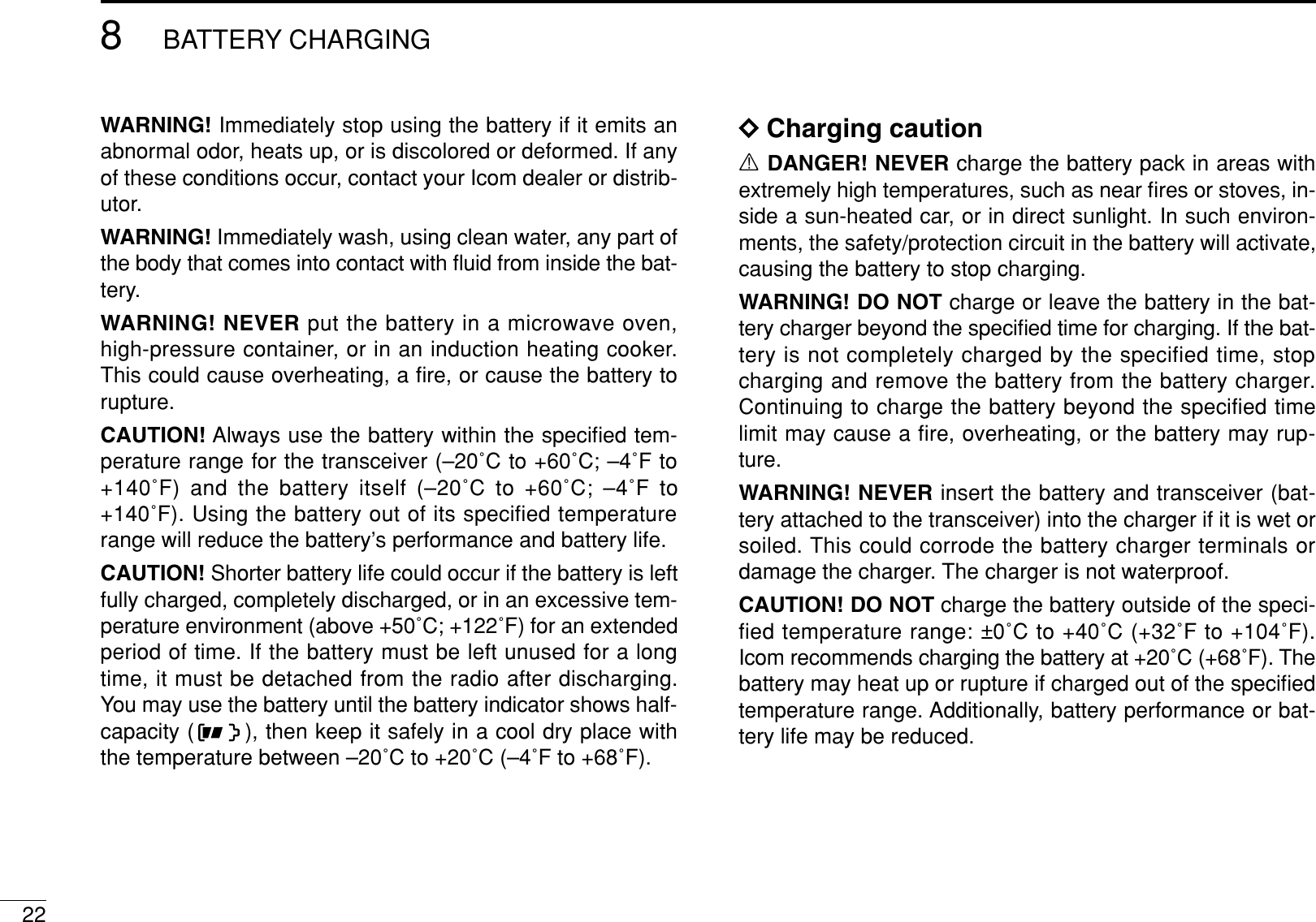
![53PANEL DESCRIPTION3tFAVORITE/TAG KEY [FAV•TAG]➥While pushing and holding this key, push [Y]/[Z] to se-lect the favorite (TAG) channels in the selected channelgroup in sequence. (p. 8)• Pushing this key only selects the favorite (TAG) channels up-ward.➥Push and hold for 1 sec. to set or clear the displayedchannel as a TAG (scanned) channel. (p. 15)➥While pushing and holding this key, turn power ON toclear or set all TAG channels (when no TAG channelsetting) in the selected channel group. (p. 15)ySQUELCH/MONITOR KEY [SQL•MONI]➥Push this key, then adjust the squelch level with [Y]/[Z].(p. 12)➥Manually opens the squelch for monitoring the channelwhile pushing and holding. (p. 13)➥While pushing and holding this key, turn power ON toenter the set mode. (p. 17)uTRANSMIT POWER/LOCK KEY [H/L•LOCK]➥Selects high or low power when pushed. (p. 10)➥Toggles the key lock function ON/OFF when pushed andheld for 1 sec. (p. 12)iCHANNEL UP/DOWN KEYS [Y]/[Z]➥Selects an operating channel. (pgs. 8, 9)➥Selects the set mode condition of the item. (p. 17)➥Checks TAG channels or changes scanning directionduring scan. (p. 15)oSCAN/DUAL KEY [SCAN•DUAL]➥Push to start and stops normal or priority scan. (p. 15)➥Push and hold for 1 sec. to enter watch mode. (p. 16)➥Exits watch mode when pushed during watch operation.(p. 16)!0 VOLUME KEY [VOL•MUTE]➥Push this key, then adjust the volume level with [Y]/[Z].(p. 11)➥Push and hold for 1 sec. to activate the volume mutefunction. (p. 11)!1 CHANNEL 16 KEY [16•9]➥Push to select Channel 16. (p. 8)➥Push and hold for 1 sec. to select the call channel. (p. 8)➥Enters call channel programming condition when the callchannel is selected and this key is pushed and held for 3sec. (p. 11)➥Push to exit set mode during set mode operation. (p. 17)!2 PTT SWITCH [PTT]Push and hold to transmit; release to receive. (p. 10)](https://usermanual.wiki/ICOM-orporated/298700/User-Guide-735497-Page-11.png)
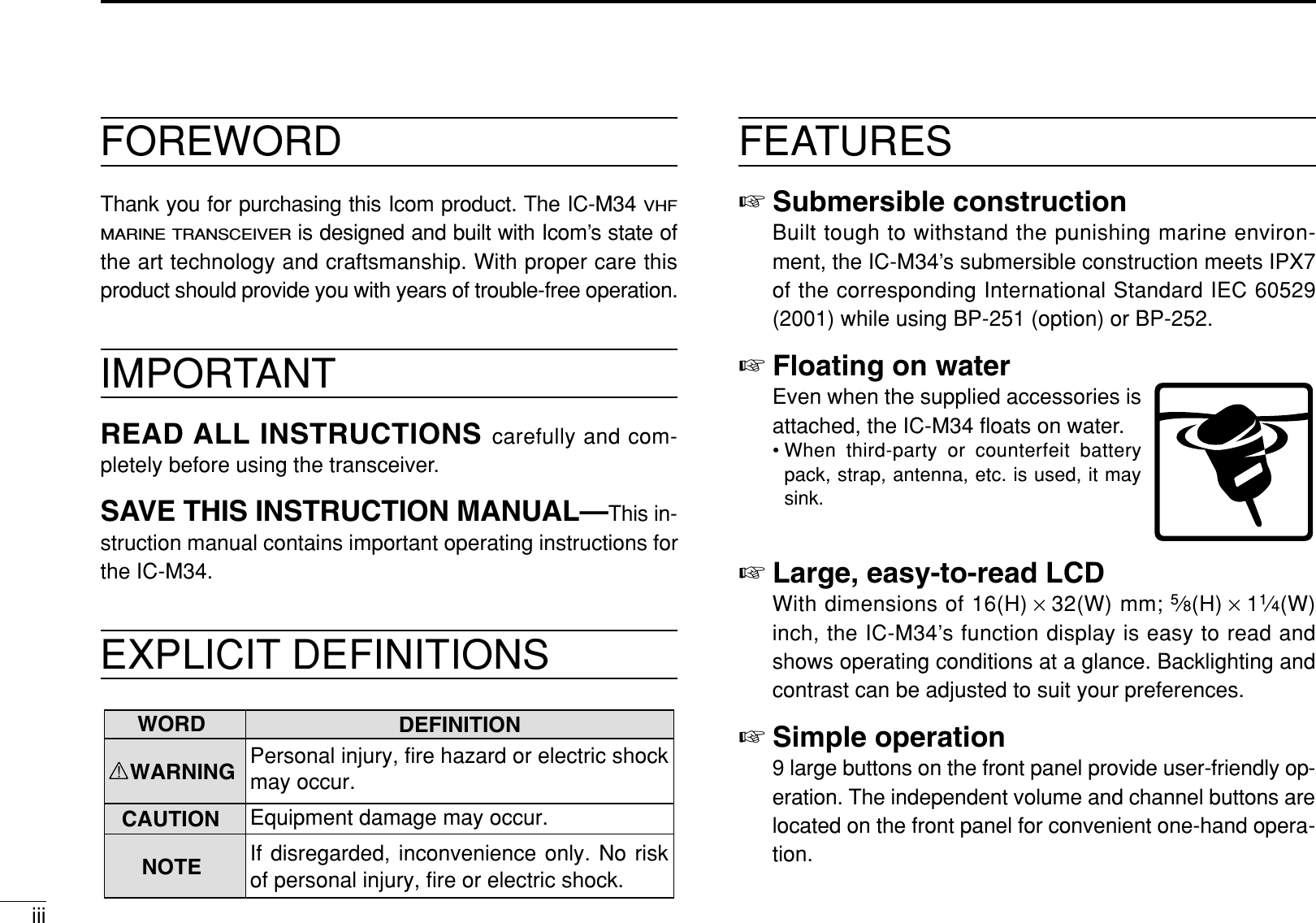
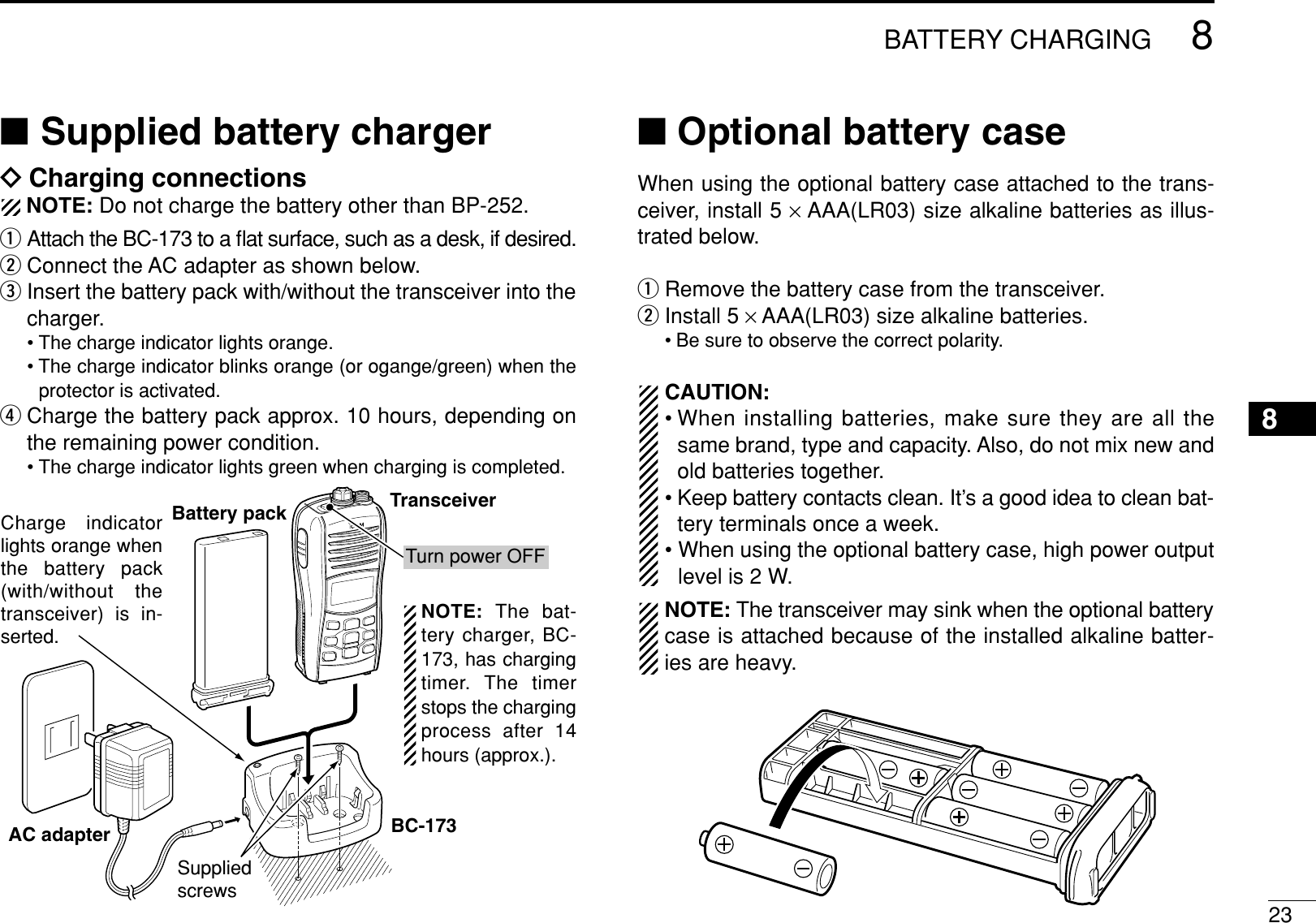
![8BASIC OPERATION4■Channel selectionIMPORTANT!: Prior to using the transceiver for the firsttime, the battery pack must be fully charged for optimumlife and operation. To avoid damage to the transceiver, turnthe power OFF while charging.DChannel 16Channel 16 is the distress and safety channel. It used for es-tablishing initial contact with a station and for emergencycommunications. Channel 16 is monitored during both Dual-watch and Tri-watch. While standing by, you must monitorChannel 16.qPush [16] momentarily to select Channel 16.wPush [CH/WX] to return to the condition before selectingChannel 16, or push [Y]/[Z]to select a channel.Convenient!While pushing and holding [FAV], push [Y]/[Z] to select thefavorite (TAG) channels in the selected channel group in se-quence.• Pushing [FAV] only selects the favorite (TAG) channels upward.• The favorite channels are set by the TAG channel setting. (p. 15)DChannel 9 (Call channel)Each regular channel group has separate leisure-use callchannels. The call channel is monitored during Tri-watch. Thecall channels can be programmed (p. 11) and are used tostore your most often used channel in each channel group forquick recall.qPush and hold [9] (16) for 1 sec. to select the call channelof the selected channel group.•“CALL” and call channel number appear.• Each channel group may have an independent call channel afterprogramming a call channel. (p. 11)wPush [CH/WX] to return to the condition before selectingcall channel, or push [Y]/[Z]to select a channel.Push and holdfor 1 sec.Push](https://usermanual.wiki/ICOM-orporated/298700/User-Guide-735497-Page-14.png)
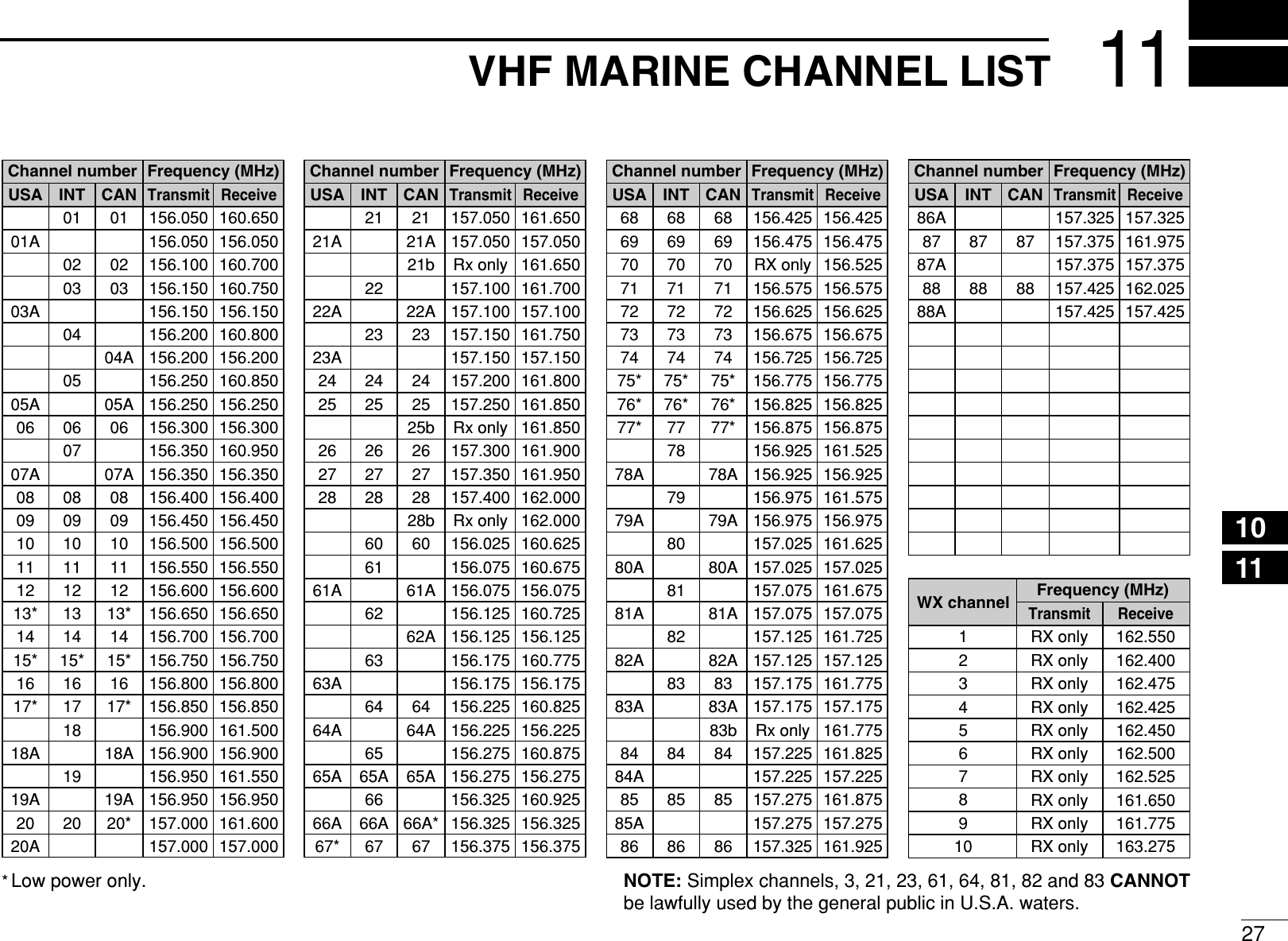
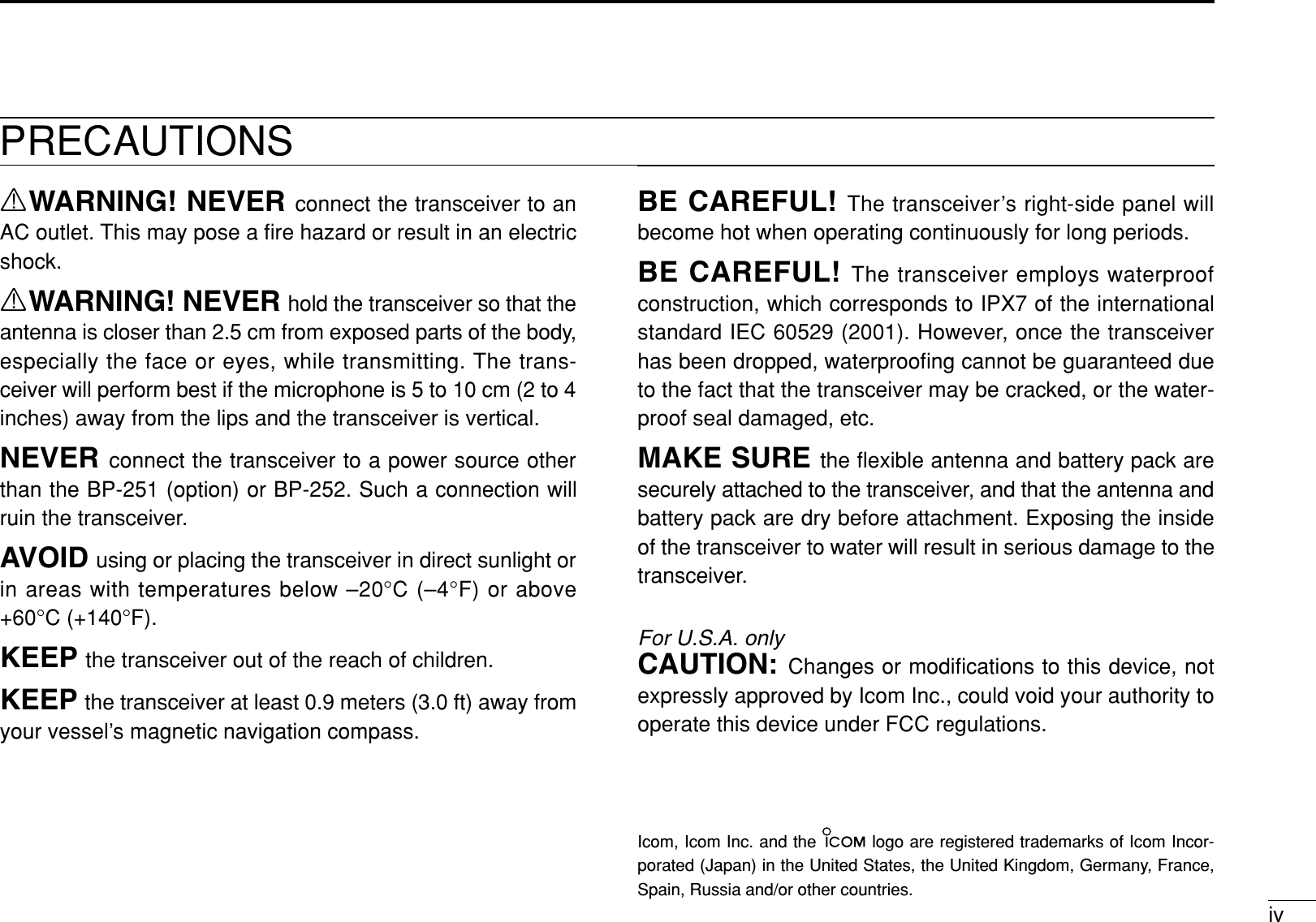
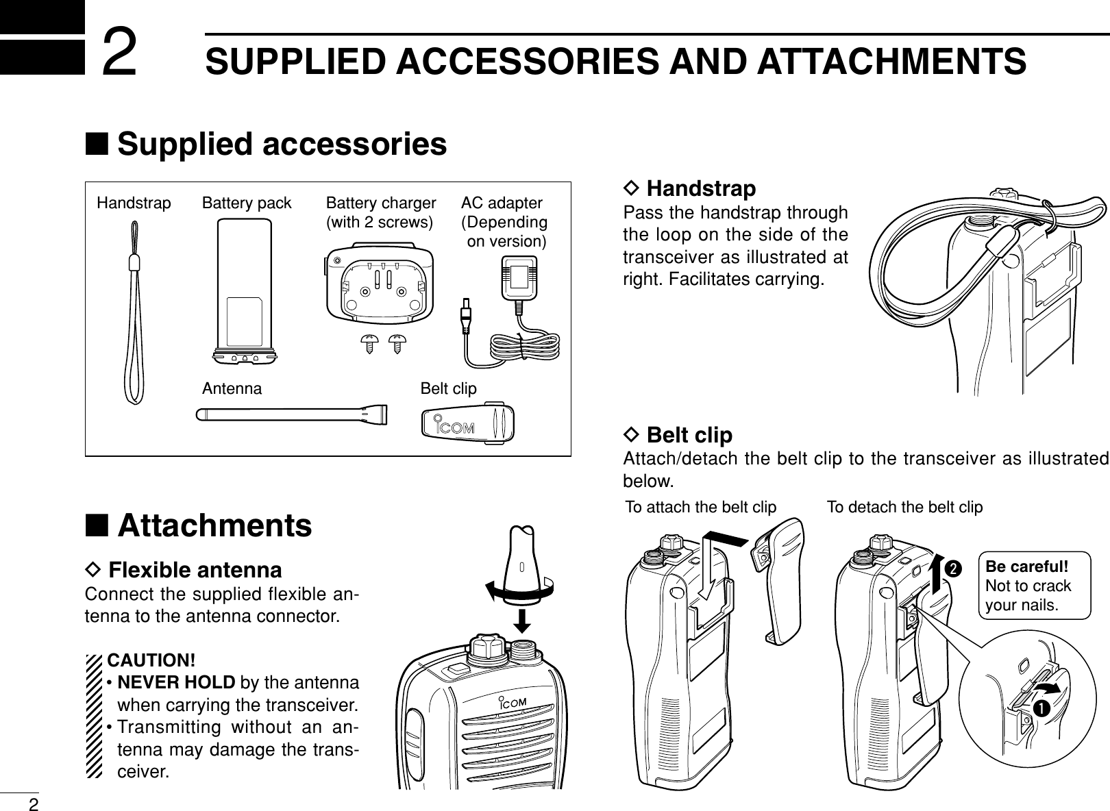
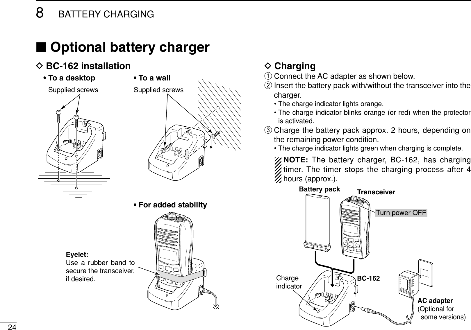
![94BASIC OPERATION4DU.S.A., International and Canadian channelsThe IC-M34 is pre-programmed with 59 U.S.A., 59 Interna-tional and 63 Canadian channels. These channel groups maybe specified for the operating area.qPush [CH/WX] to select a regular channel.• If a weather channel appears, push [CH/WX] again.wPush and hold [U/I/C] (CH/WX) for 1 sec. several times tochange the channel group.• U.S.A., International and Canadian channel groups can be se-lected in sequence.ePush [Y]/[Z]to select a channel.•“DUP” appears for duplex channels.DWeather channelsThe IC-M34 has 10 pre-programmed weather channels.These are used for monitoring broadcasts from the NOAA(National Oceanographic and Atmospheric Administration).The transceiver can automatically detect a weather alert toneon the selected weather channel while receiving the channelor while scanning. (p. 18)qPush [CH/WX] once or twice to select a weather channel.•“WX” appears when a weather channel is selected.•“WX ALT” appears when the weather alert function is turned ON.(p. 18)wPush [Y]/[Z]to select a weather channel.Push once or twice.Weather alert is OFF. Weather alert is ON.Push and holdU.S.A. channelsInternational channels Canadian channels for 1 sec.](https://usermanual.wiki/ICOM-orporated/298700/User-Guide-735497-Page-15.png)
![104BASIC OPERATION■Receiving and transmittingCAUTION: Transmitting without an antenna will damagethe transceiver.qPush and hold [PWR] to turn power ON.wSet the audio and squelch levels.➥Push [SQL], and push [Z]several times to open the squelch.➥Push [VOL], then push [Y]/[Z]to adjust the volume level.➥Push [SQL], and push [Y]until the noise disappears.ePush [Y]/[Z]to select the desired channel.• When receiving a signal, “ ” appears and audio is emittedfrom the speaker.• Further adjustment of the audio may be necessary at this point.rPush [H/L] to select the output power if necessary.•“LOW” appears when low power is selected; no indication whenhigh power is selected.• Choose low power to conserve battery power, choose highpower for longer distance communications.• Some channels are for low power only.tPush and hold [PTT] to transmit, then speak into themicrophone.• “ ” appears.• Channel 70 cannot be used for transmission.yRelease [PTT] to receive.IMPORTANT: To maximize the readability of your trans-mitted signal, pause a few sec. after pushing [PTT], holdthe microphone 2 to 4 inches (5 to 10 cm) from your mouthand speak into the microphone at a normal voice level.NOTE: The transceiver has a power save function to con-serve the battery power. The power save function activatesautomatically when no signal is received for 5 sec.For U.S.A version:To prevent accidental prolonged trans-mission, etc., the IC-M34 has a time-out timer function.This timer cuts a transmission OFF after 5 min. of continu-ous transmission.Microphoner Set output powerq Power ONw Set the squelch levelw Set volumet Push to transmity Release to receiveeSet channelSet the squelch and volume level.w](https://usermanual.wiki/ICOM-orporated/298700/User-Guide-735497-Page-16.png)
![114BASIC OPERATION4■Call channel programmingCall channel is used to select Channel 9 (default), however,you can program the call channel with your most often-usedchannels in each channel group for quick recall.qPush and hold [U/I/C] (CH/WX) for 1 sec. several times toselect the desired channel group (U.S.A., International orCanada) to be programmed.wPush and hold [9] (16) for 1 sec. to select the call channelof the selected channel group.•“CALL” and call channel number appear.ePush and hold [9] (16) again for 3sec. (until a long beep changes to2 short beeps) to enter call chan-nel programming condition.• Channel number starts blinking.rPush [Y]/[Z]to select the desiredchannel.tPush [16] to program the dis-played channel as the call chan-nel.• The channel number stops blinking.■Adjusting the volume levelThe volume level can be adjusted with [VOL] and [Y]/[Z].qPush [VOL], then adjust the volume level with [Y]/[Z].•“VOL” indicator starts blinking.• There are 31 volume levels and OFF.• When no key is pushed for 5 sec., the transceiver returns to nor-mal condition.wPush [VOL] again to return to normal condition.■Volume mute functionThe volume mute function can be activated temporarily with[MUTE] (VOL).qPush and hold [MUTE] (VOL) for 1 sec to activate the vol-ume mute function.• The audio is muted.• The volume level indicator starts blinking.wPush [VOL] again or turn power OFF to turn the volumemute function OFF.Indicates the volume level.Blinks during volume level adjustment.](https://usermanual.wiki/ICOM-orporated/298700/User-Guide-735497-Page-17.png)
![124BASIC OPERATION■Adjusting the squelch levelTo adjust the IC-M34’s squelch level, use the [Y]/[Z]keys asdesired below. In order to receive signals properly, as well asfor the scan to function effectively, the squelch must be ad-justed to the proper level.qPush [SQL], then adjust the squelch level with [Y]/[Z].•“SQL” indicator starts blinking.• There are 11 squelch levels to choose from: OP is completelyopen; 10 is tight squelch; 1 is loose squelch level.• When no key is pushed for 5 sec., the transceiver returns to nor-mal condition.wPush [SQL] again to return to normal condition.■Lock functionThis function electronically locks all keys (except for [PTT],[SQL•MONI],[VOL•MUTE],[H/L•LOCK] and [Y]/[Z]*) toprevent accidental channel changes and function access.➥Push and hold [LOCK] (H/L) for 1 sec. to turn the lockfunction ON and OFF.* Activates after pushing [VOL] or [SQL] only.■Automatic backlightingThis function is convenient for nighttime operation. The auto-matic backlighting can be activated in set mode. (p. 19)➥Push any key except for [PTT] to turn the backlighting ON.• The backlighting is automatically turned OFF after 5 sec. of in-activity.Push and holdfor 1 sec.Appears while the lock function is used.Blinks during squelch level adjustment.Indicates the squelch level.](https://usermanual.wiki/ICOM-orporated/298700/User-Guide-735497-Page-18.png)
![134BASIC OPERATION4■Monitor functionThe monitor function releases the noise squelch mute. Seep. 5 for details of the monitor key action.➥The monitor function activates while pushing and holding[MONI] (SQL).• “ ” blinks and audio is emitted.■AquaQuake water draining functionThe IC-M34 uses a new technology to clear water away fromthe speaker grill: AquaQuake. AquaQuake helps drain wateraway from the speaker housing (water that might otherwisemuffle the sound coming from the speaker). The IC-M34emits a vibrating beep when this function is being used.➥Push and hold both [SCAN] and [H/L].• A low beep tone sounds for 9 sec. to drain water, regardless ofvolume level setting.• The transceiver never accepts a key operation while theAquaQuake function is activated. And this function won’t be acti-vated when an optional speaker-microphone is connected.Push and holdBlinks while the monitor function is used.](https://usermanual.wiki/ICOM-orporated/298700/User-Guide-735497-Page-19.png)

![155SCAN OPERATION■Setting TAG channelsFor more efficient scanning, add the desired channels as TAGchannels or clear the TAG for unwanted channels.Channels that are not tagged will be skipped during scanning.TAG channels can be assigned to each channel group(U.S.A., International and Canada) independently.qPush and hold [U/I/C] (CH/WX) for 1 sec. several times toselect the desired channel group, if desired.wSelect the desired channel to be set as a TAG channel.ePush and hold [TAG] (FAV) for 1 sec. to set the displayedchannel as a TAG channel.• “ ” appears in the function display.rTo cancel the TAG channel setting, push and hold [TAG](FAV) for 1 sec.• “ ” disappears.✔Clearing (or setting) all tagged channelsWhile pushing and holding [TAG] (FAV), turn power ON toclear all TAG channels in the selected channel group.• Repeat above procedure to set all channels as TAG channels(when no TAG channel setting).■Starting a scanSet the weather alert function, priority scan function, scan re-sume timer and auto scan function in advance, using setmode. (pgs. 18, 19)qPush and hold [U/I/C] (CH/WX) for 1 sec. several times toselect the desired channel group, if desired.• When the weather alert function is in use, select the desiredweather channel with [CH/WX] and [Y]/[Z].wPush [SCAN] to start priority or normal scan.•“SCAN” blinks in the function display.• “16” appears on the sub channel readout during priority scan.• When a signal is received, scan pauses until the signal disap-pears or resumes after pausing 5 sec. according to scan resumetimer setting. (Channel 16 is still monitored during priority scan.)• Push [Y]/[Z] to check the scanning TAG channels, change thescanning direction or resume the scan manually.eTo stop the scan, push [SCAN].•“SCAN” disappears.• Pushing [PTT],[16],[CH/WX] or [FAV] also stops the scan.[Example]: Starting a normal scan.5Scan startsto stop the scanPushPushWhen a signal is received](https://usermanual.wiki/ICOM-orporated/298700/User-Guide-735497-Page-21.png)
![16DUALWATCH/TRI-WATCH6■DescriptionDualwatch monitors Channel 16 while you are receiving on another channel; Tri-watch monitors Channel 16 and thecall channel while receiving another channel. Dualwatch/Tri-watch is convenient for monitoring Channel 16 when you areopening on another channel.■OperationqSelect Dualwatch or Tri-watch in set mode. (p. 19)wSelect the desired channel.ePush and hold [DUAL] (SCAN) for 1 sec. to start Dual-watch or Tri-watch (depending on set mode setting).•“DUAL” blinks during dualwatch; “TRI” blinks during tri-watch.• A beep tone sounds when a signal is received on Channel 16.• Tri-watch becomes dualwatch when receiving a signal on the callchannel.rTo cancel dualwatch/tri-watch, push [SCAN] again.DUALWATCH/TRI-WATCH SIMULATION• If a signal is received on Channel 16, dualwatch/tri-watchpauses on Channel 16 until the signal disappears.• If a signal is received on the call channel during Tri-watch,Tri-watch becomes Dualwatch until the signal disappears.• To transmit on the selected channel during Dualwatch/Tri-watch, push and hold [PTT].Dualwatch Tri-watchCall channel[Example]: Operating Tri-watch on INT channel 07.Tri-watch starts. Signal is received on call channel.Signal received on Channel 16 takes priority.Tri-watch resumes after the signal disappears.](https://usermanual.wiki/ICOM-orporated/298700/User-Guide-735497-Page-22.png)
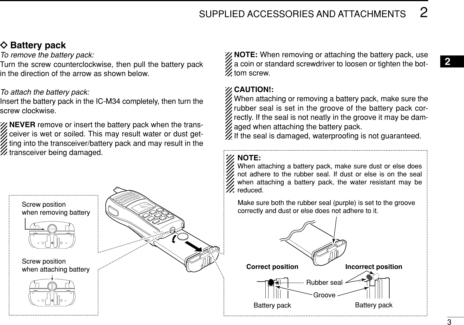
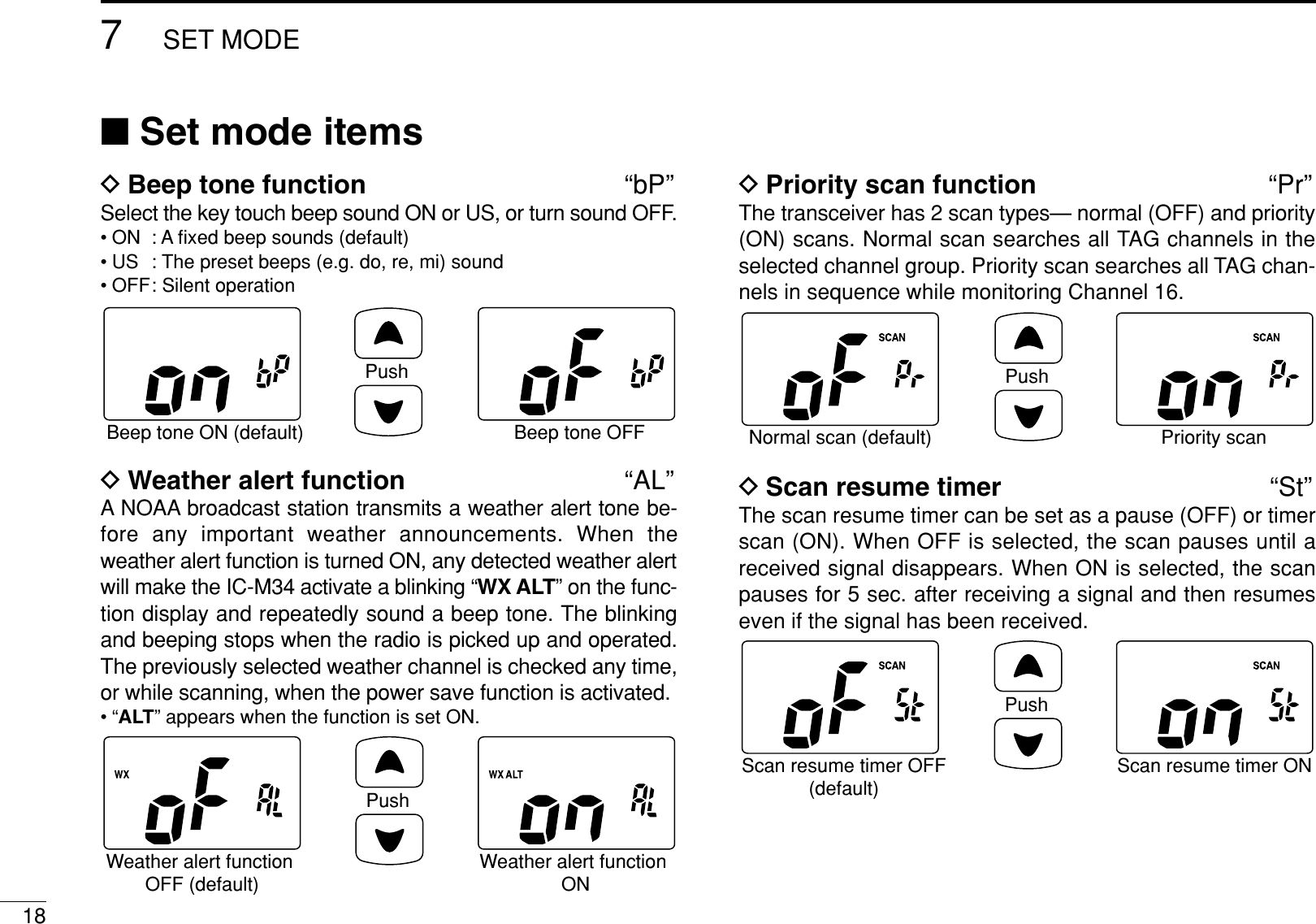
![177SET MODE67■Set mode programmingSet mode is used to change the condition of 12 transceiverfunctions: beep tone function, weather alert function, priorityscan function, scan resume timer, auto scan function, dual/tri-watch function, monitor key action, automatic backlighting,LCD contrast setting, power save function, squelch sensitivityand low fix function*.*Appears only when the optional battery case is attached.DSet mode operationqTurn power OFF.wWhile pushing [SQL], turn power ON to enter set mode.• “bP” appears.ePush [SQL] to select the desired item, if necessary.rPush [Y]/[Z]to select the desired condition of the item.tTo exit set mode, push [16].DSET MODE ITEMS (The display shows the default settings, and the selected item is displayed in the dotted circle.)• Auto scanStarting item• Beep tone• Low fix* • Scan resume timer• Dual/Tri-watch• Automatic backlighting• Power save • LCD contrast • Monitor key action• Squelch sensitivity• Priority scan• Weather alert: Push +[Z]: Push or +[Y]*Appears only when the optional battery case is attached.](https://usermanual.wiki/ICOM-orporated/298700/User-Guide-735497-Page-23.png)
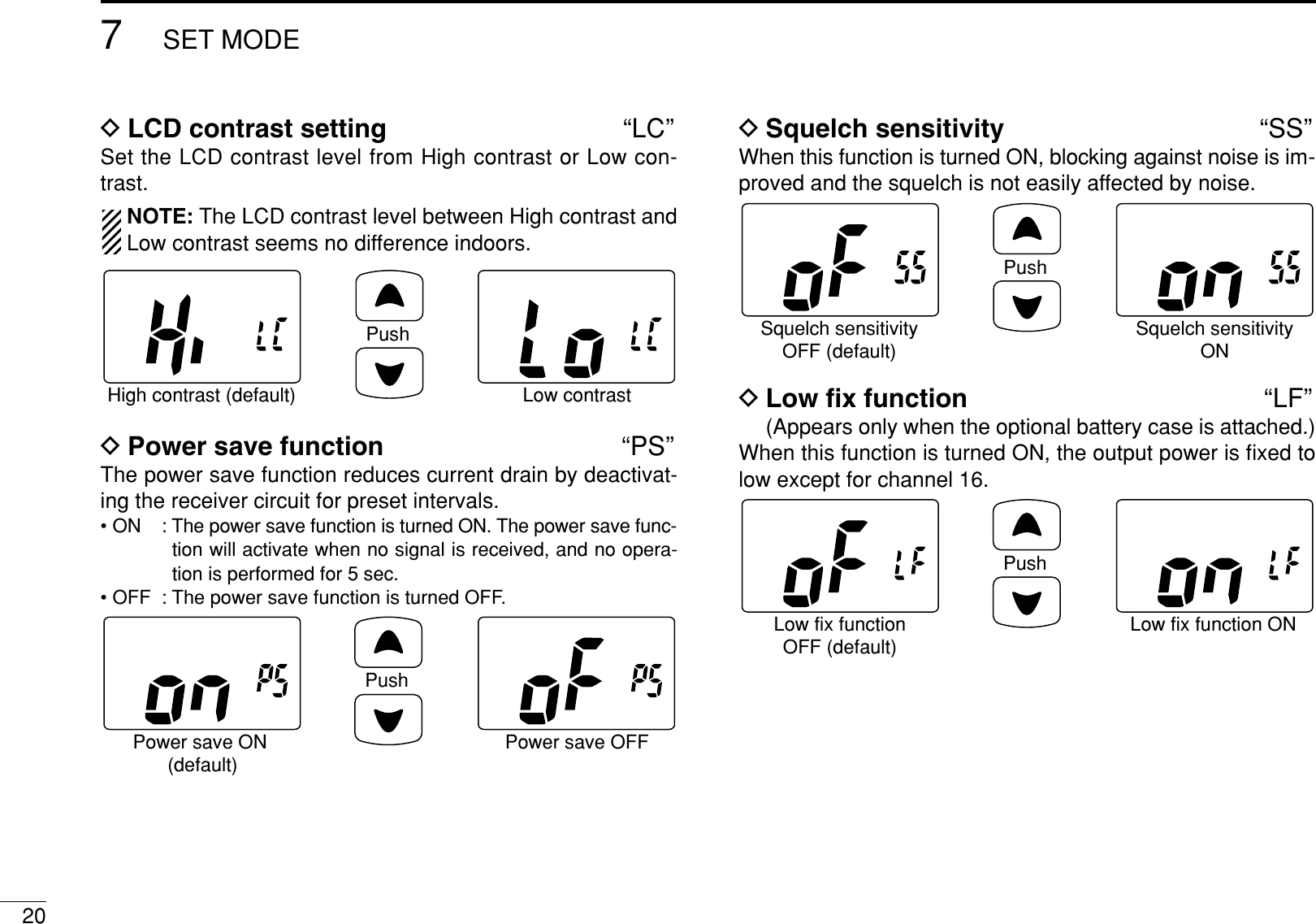
![197SET MODE7DAuto scan function “AS”The auto scan function starts the desired scan automaticallywhen no signal is received, and no operation is performed for30 sec.DDual/Tri-watch function “dt”This item selects dual or tri-watch as desired. See p. 16 fordetails.DMonitor key action “Sq”The monitor key action cuts off the squelch function tem-porarily. This key action contains PUSH (Pu) or HOLD (Ho)settings as shown below.• Pu (PUSH): After pushing [MONI] (SQL) for 1 sec., the squelch opensand emits audio. The squelch is held open while contin-uously pushing and holding [MONI] (SQL). (default)• Ho (HOLD): After pushing [MONI] (SQL) for 1 sec., the squelchopens and emits audio even [MONI] (SQL) is released.To close the squelch, push any key.DAutomatic Backlighting “bL”This function is convenient for nighttime operation. The back-light can be selected from ON and OFF.• The backlight is automatically activated when any key except for[PTT] is pushed.• The backlight is automatically turned OFF after 5 sec. of inactivity.PushAuto backlighting ON(default)Auto backlighting OFFPushPush setting (default) Hold settingPushDualwatch function(default)Tri-watch functionPushAuto scan OFF (default) Auto scan ON](https://usermanual.wiki/ICOM-orporated/298700/User-Guide-735497-Page-25.png)
![259OPTIONAL SPEAKER-MICROPHONE12345678910111213141516■HM-165 descriptionsNEVER immerse the connector in water. If the connector be-comes wet, be sure to dry it BEFORE attaching it to the trans-ceiver.NOTE: The microphone is located at the top of thespeaker-microphone, as shown in the diagram above. Tomaximize the readability of your transmitted signal (voice),hold the microphone approx. 2.5 cm (1 inch) from yourmouth, and speak in a normal voice level.■AttachmentTurn power OFF before attaching the speaker-microphone.Then, insert the speaker-mic connector onto the [SP MIC]connector and carefully screw it tight, as shown in the dia-gram below. Be careful not to cross-thread the connection.IMPORTANT: KEEP the transceiver’s [SP MIC] connectorcap attached when the speaker-microphone is not in use.If the cover is not attached, water will get into the trans-ceiver. Moreover, the terminals (pins) will become rusty, orthe transceiver will function abnormally if the connector hasbecome wet.CAUTION: Attach the speaker-microphone’sconnector securely to prevent accidental dropping, or water intrusion in the connector.Detaching:Rotate the [SP MIC] cap counter-clockwise (q), then detach it (w).Attaching:Attach the [SP MIC] cap (q), then rotate it clockwise completely (w).qwqwPTT switchTransmits during push.Receives during release.MicrophoneSpeakerAlligator type clipTo attach the speaker-mic.to your shirt or collar, etc.Turn the transceiver power OFF when connecting the HM-165.](https://usermanual.wiki/ICOM-orporated/298700/User-Guide-735497-Page-31.png)
![26TROUBLESHOOTING10PROBLEM POSSIBLE CAUSE SOLUTION REF.No sound from speaker. • Squelch level is too deep.• Volume level is too low.• Speaker has been exposed to water.p. 12p. 11—• Set squelch to the threshold point.• Push [Y]/[Z]after pushing [VOL] to set asuitable level.• Drain water from the speaker.The transceiver doesnot turn ON.• The battery is exhausted.• The battery pack is not attached correctly.p. 21p. 3• Recharge the battery pack.• Attach the battery pack correctly.Transmitting is impossi-ble, or high power cannot be selected.• Some channels are for low power or re-ceive only.• The battery is exhausted.• The battery over charged.• The output power is set to low.pgs. 8,9, 21p. 21—p. 10• Change channels.• Recharge the battery pack.• Verify the battery voltage is correct.• Push [H/L] to select high power.The displayed channelcannot be changed.• Lock function is activated. • Push and hold [LOCK] (H/L) for 1 sec. tocancel the function.p. 12Scan does not start. • “TAG” channels are not programmed. • Set the desired channels as “TAG” channels. p. 15No beeps. • Beep tones are turned OFF. • Set the beep tones to ON (Fix Beep/UserBeep) in set mode.p. 18Battery voltage error • The connected battery pack’s voltage ismore than 11 V.• Verify the battery voltage is correct. —](https://usermanual.wiki/ICOM-orporated/298700/User-Guide-735497-Page-32.png)