ICOM orporated 305600 VHF Mobile Transceiver User Manual Manual
ICOM Incorporated VHF Mobile Transceiver Manual
UserManual.wiki
>
ICOM orporated
>
305600 User Manual
Manual
Navigation menu
Upload a User Manual
Namespaces
Wiki Guide
HTML
PDF
Info
Views
User Manual
Discussion / Help
Navigation
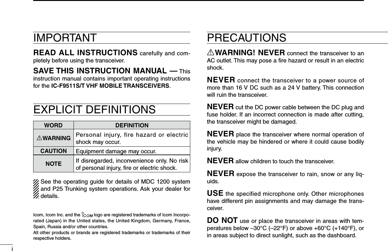
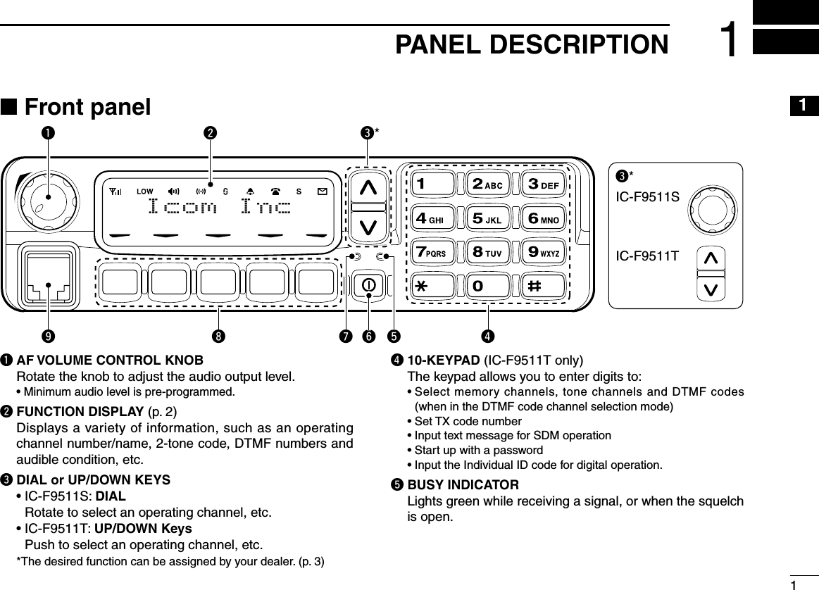
![21PANEL DESCRIPTIONy POWER SWITCH [POWER]Push to turn the power ON and OFF. • The following functions are available at power ON as options: - Automatic scan start - Password prompt - Set modeu TRANSMIT INDICATOR Lights red while transmitting.i DEALER-PROGRAMMABLE KEYS Desired functions can be programmed independently by your dealer. (p. 3) In this instruction manual, these keys are from the left, called [P0]/[P1]/[P2]/[P3]/[P4].o MICROPHONE CONNECTOR Connect the supplied microphone or optional DTMF mi-crophone. NEVER connect non-specified microphones. The pin assignments may be different and the transceiver may be damaged.D MICROPHONEThe supplied microphone has a PTT switch and a hanger hook.• The following functions are available when the microphone is on or off hook: - Automatic scan start when on hook. - Automatic priority channel selection when off hook. - Sets to ‘Inaudible’ condition (mute condition) when on hook. - Sets to ‘Audible’ condition (unmute condition) when off hook.n Function display1 3 6 . 1 N a r q w e r t y u i o!1!0q SIGNAL STRENGTH INDICATOR Indicates relative signal strength level.w LOW POWER INDICATOR Appears when low output power is selected.e AUDIBLE INDICATOR ➥ Appears when the channel is in the ‘audible’ (unmute) condition. ➥ Appears when the specified 2-tone code is received.r COMPANDER INDICATOR Appears when the compander function is activated.t SCRAMBLER INDICATOR Appears when the voice scrambler function is activated.](https://usermanual.wiki/ICOM-orporated/305600/User-Guide-871594-Page-6.png)
![31PANEL DESCRIPTION1y BELL INDICATOR Appears/blinks when the specific 2-tone code is received, according to the pre-programming.u CALL CODE MEMORY INDICATOR Appears when the call code memory is selected.i SDM MEMORY INDICATOR Appears when the SDM memory is displayed.o SDM INDICATOR Appears when an SDM is received, or a transmit SDM is selected.!0 ALPHANUMERIC DISPLAY Displays an operating channel number, channel name, Set mode contents, DTMF code, etc. The indication mode can be selected from 1 line or 2 lines. Ask your dealer for details. In this instruction manual, the LCD illustration is de-scribed using the 2 lines indication mode.!1 ACTIVATED KEY INDICATOR Appears above the key assigned as [DIGITAL] key when that key has been activated.n Programmable function keysThe following functions can be assigned to [DIAL]*, [UP], [DOWN], [P0], [P1], [P2], [P3] and [P4] programmable func-tion keys.Consult your Icom dealer or system operator for details con-cerning your transceivers programming.If the programmable function names are bracketed in the fol-lowing explanations, the specific key is used to activate the function depends on the programming.* The functions you can assign to [DIAL] are limited. (Only functions marked with ✩ can be assigned.)✩ CH UP AND DOWN KEYS ➥ Push (or Rotate)* to select an operating channel.➥ Push (or Rotate)* to select a transmit code channel after pushing [TX Code CH Select].➥ Push (or Rotate)* to select a DTMF channel after pushing [DTMF Autodial].➥ Push (or Rotate)* to select a scan group after pushing and holding [Scan A Start/Stop]/[Scan B Start/Stop].➥ Push (or Rotate)* to select an Individual ID code or Talk-group ID code after pushing [Individual] or [Talkgroup].* Rotate when this function is assigned to [DIAL].✩ ZONE UP AND DOWN KEY (This function is for [DIAL] only)Rotate to select the desired zone.](https://usermanual.wiki/ICOM-orporated/305600/User-Guide-871594-Page-7.png)
![41PANEL DESCRIPTIONZONE KEYPush this key, then select the desired zone using [CH Up]/ [CH Down]. What is “zone”?—The desired channels are assigned into a zone according to the intended use for grouping. For example, ‘Staff A’ and ‘Staff B’ are assigned into a “Business” zone, and ‘John’ and ‘Cindy’ are assigned into a “Private” zone.SCAN A START/STOP KEY➥ This key’s operation depends on the Power ON Scan set-ting. When the power ON scan function is turned OFF; Push to start and cancel scanning operation. In case of transmission during scan, cancels scanning. When the power ON scan function is turned ON; Push to pause scanning. Scanning resumes after a specified time period has passed. In case of transmission during scan, pauses scanning. Scanning resumes after a specified time period has passed after the transmission is finished.➥ Push and hold this key for 1 sec. to indicate the scan group, then select the desired group using [CH Up]/[CH Down].SCAN B START/STOP KEY➥ Push to start and cancel scanning operation. In case of transmission during scan, pauses scanning. Scanning re-sumes after a specified time period has passed after the transmission is finished.➥ Push and hold this key for 1 sec. to indicate the scan group, then select the desired group using [CH Up]/ [CH Down].SCAN ADD/DEL (TAG) KEYPush to add or delete the selected channel to/from the scan group.PRIO A/B KEYS➥ Push to select Priority A or Priority B channel.➥ Push and hold [Prio A (Rewrite)] to rewrite the Prio A channel.MR-CH 1/2/3/4 KEYSPush to select an operating channel directly.MONI (AUDI) KEYMute and release the CTCSS (DTCS) or 2-tone squelch mute. Open any squelch/deactivate any mute while pushing this key. (LMR operation only)](https://usermanual.wiki/ICOM-orporated/305600/User-Guide-871594-Page-8.png)
![51PANEL DESCRIPTION1PUBLIC ADDRESS KEYWhile in the hailer mode, push this key for the audio output via the hailer amplifier. Ask your dealer for details.While in the normal mode, the audio output via the cable can be controlled from the transceiver separately from [VOL] control knob.• This audio output can be used as a ‘public address’ function when an external audio amplifier and speaker are connected additionally.• Push this key, then speak into the microphone while pushing the PTT switch.• [CH Up]/[CH Down] allow you to set the audio output level from minimum to maximum.RX SPEAKER KEYWhile in the hailer mode, the external speaker drive function is also available simultaneously when the external connec-tions are made for the ‘public address’ function. The received audio can be heard via the external speaker when this key is pushed.• This function is useful when you are out of the vehicle.• The audio output level is linked to the transceiver’s volume control.LIGHT KEYPush to turn the transceiver’s backlight ON for about 5 sec. when the backlight function is turned OFF in user set mode.LOCK KEYPush and hold to electronically lock all programmable keys except the following:[Call] (incl. Call A and Call B), [Moni(Audi)] and [Emergency].HIGH/LOW KEYPush to select the transmit output power temporarily or per-manently, depending on the pre-setting.• Ask your dealer for the output power level for each selection.C.TONE CH ENT KEYPush to select the continuous tone channel using [CH Up]/ [CH Down] to change the tone frequency/code setting after pushing this key. The selected channel remains set as the continuous tone channel until another channel is designated as such.TALK AROUND KEYTurn the talk around function ON and OFF.• The talk around function equalizes the transmit frequency to the receive frequency for transceiver-to-transceiver communication.WIDE/NARROW KEYPush to toggle the IF bandwidth between wide and narrow.DTMF AUTODIAL KEY➥ Push to enter the DTMF channel selection mode. Then select the desired DTMF channel using [CH Up]/[CH Down].➥ After selecting the desired DTMF channel, push this key to transmit the DTMF code.SCRAMBLER FUNCTIONPush to toggle the voice scrambler function ON and OFF.](https://usermanual.wiki/ICOM-orporated/305600/User-Guide-871594-Page-9.png)
![61PANEL DESCRIPTIONRE-DIAL KEYPush to transmit the last-transmitted DTMF code.CALL KEYSPush to transmit a 2-tone ID code.• Call transmission is necessary before calling another station depending on your signalling system.• [Call A] and/or [Call B] may be available when your system employs selective ‘Individual/Group’ calls. Ask your dealer which call is assigned to each key.EMERGENCY KEYS➥ Push and hold to transmit an emergency call. ➥ When [Emergency Single (Silent)] or [Emergency Repeat (Silent)] is pushed, an emergency call is transmitted with-out a beep emission and LCD indication change. • If you want to cancel the emergency call, push (or push and hold) the key again before transmitting the call. • The emergency call is transmitted one time only or repeatedly until receiving a control code depending on the pre-setting.SURVEILLANCE KEYPush to turn the surveillance function ON or OFF.When this function is turned ON, the beep is not emitted and the LCD backlight does not light when a signal is received or a key is pushed, etc.COMPANDER KEYPush to toggle the compander function ON and OFF. The compander function reduces noise components from the transmitted audio to provide clear communication.TX CODE CHANNEL SELECT KEYPush to enter the ID code channel selection mode directly. Then set the desired channel using [CH Up]/[CH Down]. (p. 11)✩ TX CODE CHANNEL UP/DOWN KEYSPush (or Rotate)* to select a TX code channel directly.* Rotate when this function is assigned to [DIAL].HOOK SCAN KEYWhen the hook on scan function is turned ON, push this key to stop scanning temporarily. Push this key again to re-start scanning.USER SET MODE KEY➥ Push and hold to enter user set mode. • During user set mode, push this key to select an item, and change the value or condition using push [CH Up]/[CH Down].➥ Push and hold this key again to exit user set mode.User set mode is also available via the ‘Power ON function.’ Refer to p. 13 also.OPT 1/2/3 KEYSPush to control the output signal level from the optional unit connector.](https://usermanual.wiki/ICOM-orporated/305600/User-Guide-871594-Page-10.png)
![71PANEL DESCRIPTION1TONE/NAC CH SELECT KEY(LMR (P25 Conventional) operation only)➥ While in the analog mode operation, push to select the continuous tone channel using [CH Up] or [CH Down] to change the tone frequency/code setting.➥ While in the digital mode operation, push to select the NAC channel using [CH Up] or [CH Down] to change the NAC code setting.➥ While in the mixed (digital and analog) mode operation, push to select the continuous tone channel using [CH Up] or [CH Down] to change the tone frequency/code setting. Then push this key to enter the setting. After that, the NAC channel selection screen appears. Select the NAC channel using [CH Up] or [CH Down] to change the NAC code setting. Then push this key to enter the setting.SCRAMBLER/ENCRYPTION KEY(LMR (P25 Conventional) operation only)➥ While in the analog mode operation, push to toggle the voice scrambler function ON and OFF.➥ While in the digital mode operation, push to toggle the encryption transmission function ON and OFF.➥ While in the mixed (digital and analog) mode operation, push to toggle the voice scrambler and encryption trans-mission functions ON and OFF, separately or simultane-ously as below.Voice scrambler function ONVoice scrambler and Encryption transmittion functions ONVoice scrambler and Encryption transmittion functions OFFEncryption transmittion function ONPUSHPUSHPUSHPUSH(appears)(appears)(appears)(disappears)](https://usermanual.wiki/ICOM-orporated/305600/User-Guide-871594-Page-11.png)
![81PANEL DESCRIPTIOND For Digital mode operation onlyINDIVIDUAL KEY➥ Push to enter the individual ID code selection mode direct-ly. Then select the desired individual ID code using [CH Up]/ [CH Down]. (p. 12)➥ Push to stop the beep emission when receiving a matched individual ID code.TALKGROUP KEY➥ Push to enter the talkgroup ID code selection mode direct-ly. Then select the desired talkgroup ID code using [CH Up]/ [CH Down]. (p. 12)➥ Push to stop the beep emission when receiving a matched talkgroup ID code.ZEROIZE KEYPush and hold to zeroize the encryption key data, pro-grammed by the FS-F9511? flash loader.ENCRYPTION KEYPush to toggle the encryption transmission function ON or OFF.When this function is turned ON, “ ” appears on the func-tion display.](https://usermanual.wiki/ICOM-orporated/305600/User-Guide-871594-Page-12.png)
![92BASIC OPERATION12n Turning power ONq Push [ ] to turn the power ON.w If the transceiver is programmed for a start up password, input the digit codes as directed by your dealer. • 10-keypad* can be used for password input. *IC-F9511T only: • The keys as below can be used for password input: The transceiver detects numbers in the same block as identical. Therefore “01234” and “56789” are the same.KEYNUMBER 0549382716P0 P4P3P2P1P0 P4P3P2P1*In this instruction manual, these keys are from the left, called [P0]/[P1]/[P2]/[P3]/[P4].e When the “PASSWORD” indication does not clear after inputting 6 digits, the input code number may be incorrect. Turn the power off and start over in this case.n Channel selectionSeveral types of channel selections are available. Methods may differ according to your system set up.NON-ZONE TYPE:Push [CH Up] or [CH Down], or rotate [CH Up/Down] to select the desired operating channel, in sequence; or, push one of [MR-CH 1] to [MR-CH 4] keys to select a channel di-rectly.ZONE TYPE:Push [Zone] then push [CH Up] or [CH Down], or rotate [Zone Up/Down] to select the desired zone.AUTOMATIC SCAN TYPE:Channel setting is not necessary for this type. When turning power ON, the transceiver automatically starts scanning. Scanning stops when receiving a call.](https://usermanual.wiki/ICOM-orporated/305600/User-Guide-871594-Page-13.png)
![102BASIC OPERATIONn Call procedureWhen your system employs tone signaling (excluding CTCSS and DTCS), the call pro cedure may be necessary prior to voice transmission. The tone signalling employed may be a se-lective calling system which allows you to call specific station(s) only and prevent unwanted stations from contacting you.q Select the desired TX code channel, 2-tone code, Indi-vidual ID code* or Talkgroup ID code* according to your System Operator’s instructions. • This may not be necessary depending on programming. • Refer to pgs. 11–13 for selection. *Digital mode operation only.w Push the call key (assigned to one of the dealer program-mable keys; except for the Digital mode operation) or [PTT].e After transmitting, the remainder of your communication can be carried out in the normal fashion.Selective calling Non-selective callingn Receiving and transmittingReceiving:q Push [ ] to turn the power ON.w Push [CH Up] or [CH Down], or rotate [CH Up/Down] to select a channel, in sequence.e When receiving a call, adjust the audio output level to a comfortable listening level.Transmitting:Wait for the channel to become clear to avoid interference.q Take the microphone off hook. • 2-tone mute may be released. (The ‘audible’ condition is se-lected and BUSY indicator lights green.) • A priority channel may be selected automatically.w Wait for the channel to become clear. • The channel is busy when BUSY indicator lights green.e Push [CALL] when initiating a call from your side. • Coded audio may be heard from the transceiver, then “ ” appears. • This operation may not be necessary depending on your signal-ing system. Ask your dealer for details.r While pushing and holding [PTT], speak into the micro-phone at your normal voice level.t Release [PTT] to receive. IMPORTANT: To maximize the readability of your signal; 1. Pause briefly after pushing [PTT]. 2. Hold the microphone 5 to 10 cm (2 to 4 inches) from your mouth, then speak into the microphone at a nor-mal voice level.](https://usermanual.wiki/ICOM-orporated/305600/User-Guide-871594-Page-14.png)
![112BASIC OPERATION2D Transmitting notes• Transmit inhibit functionThe transceiver has several inhibit functions which restrict transmission under the following conditions:- The channel is in mute condition (‘Inaudible’ condition; “ ” does not appear.)- The channel is busy.- Un-matched (or matched) CTCSS is received. (Depending on the pre-setting)- Un-matched (or matched) NAC is received.* (Depending on the pre-setting)- The selected channel is a ‘receive only’ channel.*Digital mode operation only.• Time-out timerAfter continuous transmission for the pre-programmed time period, the time-out timer is activated, causing the trans-ceiver to stop transmitting.• Penalty timerOnce the time-out timer is activated, transmission is further inhibited for a period determined by the penalty timer.D TX code channel selectionIf the transceiver has [TX Code CH Select] assigned to it, the indication can be toggled between the operating channel number (or name) and TX code channel number (or name). When the TX code channel number (or name) is displayed, [CH Up]/[CH Down] selects the TX code channel.USING [TX CODE CH SELECT] KEY:q Push [TX Code CH Select]— a TX code channel number (or name) appears.w Push [CH Up] or [CH Down], or rotate [CH Up/Down] to select the desired TX code channel.e Push [Call] to transmit the selected TX code.USING [TX CODE CH UP]/[TX CODE CH DOWN] KEY:If the transceiver has a [TX Code CH Up], [TX Code CH Down] or [TX Code CH Up/Down] key assignment, the pro-grammed TX code channel can be selected directly when pushed or rotated.](https://usermanual.wiki/ICOM-orporated/305600/User-Guide-871594-Page-15.png)
![122BASIC OPERATIOND Individual ID code selection (Digital mode operation only)If the transceiver has [Individual] assigned to it, the indication can be toggled between the operating channel number (or name) and Individual ID code (or name). When the Individual ID code (or name) is displayed, [CH Up], [CH Down] or [CH Up/Down] selects the desired Individual ID code.q Push [Individual]— an Individual ID code (or name) appears.w Push [CH Up] or [CH Down], or rotate [CH Up/Down] to select the desired Individual ID code.e Push [PTT] to transmit the selected Individual ID code.r Push [Individual]— cancels the selected Individual ID code (return to the pre-set Talkgroup ID code in the channel.)D Talkgroup ID code selection (Digital mode operation only)If the transceiver has [Talkgroup] assigned to it, the indication can be toggled between the operating channel number (or name) and Talkgroup ID code (or name). When the Talkgroup ID code (or name) is displayed, [CH Up], [CH Down] or [CH Up/Down] selects the desired Talkgroup ID code.q Push [Talkgroup]— a Talkgroup ID code (or name) appears.w Push [CH Up] or [CH Down], or rotate [CH Up/Down] to select the desired Talkgroup ID code.e Push [PTT] to transmit the selected Talkgroup ID code.r Change the channel— cancels the selected Talkgroup ID code (return to the pre-set Talkgroup ID code in the chan-nel.)D DTMF transmissionIf the transceiver has [DTMF Autodial] assigned to it, the automatic DTMF transmission function is available. Up to 8 DTMF channels are available.TO SELECT A TX CODE:q Push [DTMF Autodial]— a DTMF channel appears.w Push [CH Up] or [CH Down], or rotate [CH Up/Down] to select the desired DTMF channel.e Push [DTMF Autodial] to transmit the DTMF code in the selected DTMF channel.](https://usermanual.wiki/ICOM-orporated/305600/User-Guide-871594-Page-16.png)
![132BASIC OPERATION2n User set modeUser set mode is accessed with [User Set Mode] and allows you to set seldom-changed settings. In this case you can “customize” the transceiver operation to suit your prefer-ences and operating style.Entering the user set mode:q While pushing and holding [P1] and [P2], push [ ] to turn the power ON. Then, push and hold [P0] to enter user set mode.[P1][P0] [P2] [ ]w Push [P0] several times to select the appropriate item. Then, push [Up] or [Down] or rotate [DIAL] to set the de-sired level/condition. • Available set mode functions are Backlight, LCD Contrast, Beep, Beep Level, SQL Level, AF Min Level, Mic Gain, Horn, TIme, Date, Wake Up and Sleep.[P0] [Up]/[Down] or [DIAL]e Push [ ] again to exit set mode.[ ]User set mode is also available via a programmable key. Please refer to p. 6 [User Set Mode] section.n Scrambler functionThe voice scrambler function provides private communi-cation between stations. The frequency inversion type is equipped to all versions, moreover, the optional Rolling or Non-rolling type can be available.q Push [Scrambler] to turn the scrambler function ON. • “ ” appears.w Push [Scrambler] again to turn the scrambler func-tion OFF. • “ ” disappears.](https://usermanual.wiki/ICOM-orporated/305600/User-Guide-871594-Page-17.png)