ICOM orporated 306301 IC-FR6000, UHF FM Repeater User Manual Manual
ICOM Incorporated IC-FR6000, UHF FM Repeater Manual
UserManual.wiki
>
ICOM orporated
>
306301 User Manual
Manual
Navigation menu
Upload a User Manual
Namespaces
Wiki Guide
HTML
PDF
Info
Views
User Manual
Discussion / Help
Navigation
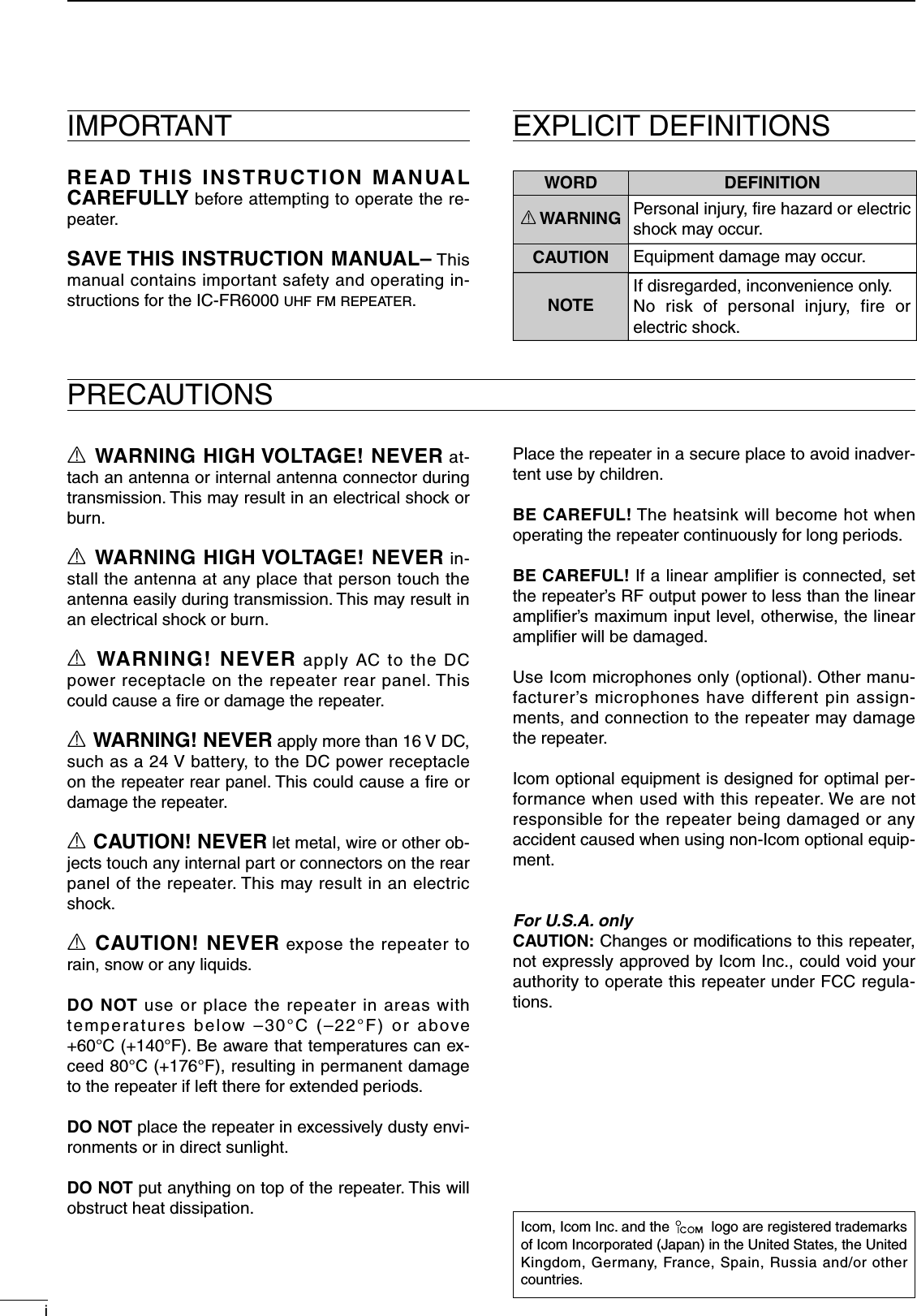
![1PANEL DESCRIPTION2001 NEW1q INTERNAL SPEAKER Monitors received signals.w VOLUME CONTROL [VOLUME] (p. 7) Adjusts the audio output level.e SELECTOR DIAL [SELECT] Rotate to adjust the squelch threshold level, select the operating channel. (Depending on the pre-programmed condition.)r POWER INDICATOR [POWER] ➥ Lights green at ‘A’ module's indicator while the repeater power is turned ON. When a channel extension module is installed: ➥ Lights green at the selected module indicator (‘A’ or ‘B’) while the repeater power is turned ON. ➥ Lights orange at the un-selected module indica-tor (‘A’ or ‘B’) while the repeater power is turned ON.t TRANSMIT INDICATOR [TX] Lights red while transmitting.y BUSY INDICATOR [BUSY] Lights green while receiving a signal or when the noise squelch is open. About [PWR], [TX] and [BUSY] indicators: ‘A’ and ‘B’ modules indicators are available for these indications. ‘A’ module's indicator correspond to the original module, and ‘B’ module's indicator correspond to an extended module.u MICROPHONE CONNECTOR [MIC] This 8-pin modular jack accepts the optional micro-phone. KEEP the [MIC] connector cover attached to the repeater when the optional microphone is not used.iqq +8 V DC output (Max. 15 mA) w Output port for PC programming e NC r M PTT (Input port for TX control) t Microphone ground y Microphone input u Ground i Input port for PC programmingi POWER SWITCH [POWER] ➥ Push to turn the repeater power ON. ➥ Push and hold for 3 sec. to turn the repeater power OFF. When a channel extension module is installed: ➥ While the repeater power is turned ON, push to select the desired module to operate the re-peater as the base station. • The power indicator of the selected module unit lights green.o DEALER-PROGRAMMABLE KEYS Desired functions can be programmed indepen-dently by your dealer. Ask your dealer for details. • Because these keys are programmable, the functions of these keys are unique to each unit.P0P1P2P3P4q w ei uoFunctiondisplayytrn Front panel](https://usermanual.wiki/ICOM-orporated/306301/User-Guide-905574-Page-6.png)
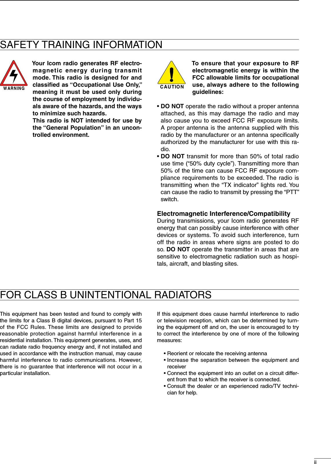
![q EXTERNAL SPEAKER CONNECTOR [SP] Connect the optional SP-22.w RECEIVE ANTENNA CONNECTOR [RX] Connects a receive antenna (impedance: 50 ˘) and inputs receiving signals.e ACCESSORY CONNECTOR [ACC] Connects to the accessory connector. • See pgs. 3 for accessory connector information.r DC POWER RECEPTACLE Connects the supplied DC power cable from this connector to an external 13.6 V DC power supply.t TRANSMIT ANTENNA CONNECTOR [TX] Connects a transmit antenna (impedance: 50 ˘) and outputs transmit signals.q w e trThe optional channel extention module can be installed.Ask your dealer for details.q SIGNAL STRENGTH INDICATOR Indicates relative signal strength level.w LOW POWER INDICATOR Appears when low output power is selected.e AUDIBLE INDICATOR Appears when the channel is in the ‘audible’ (un-mute) condition.r COMPANDER INDICATOR Appears when the compander function is activated.t SCRAMBLER/ENCRYPTION INDICATOR Appears when the voice scrambler/encryption function is activated.y ALPHANUMERIC DISPLAY Shows a variety of text or code information.n Rear panel21PANEL DESCRIPTIOND Function displayI C O M I n c.q w e r ty123456789101112131415161718192021](https://usermanual.wiki/ICOM-orporated/306301/User-Guide-905574-Page-7.png)
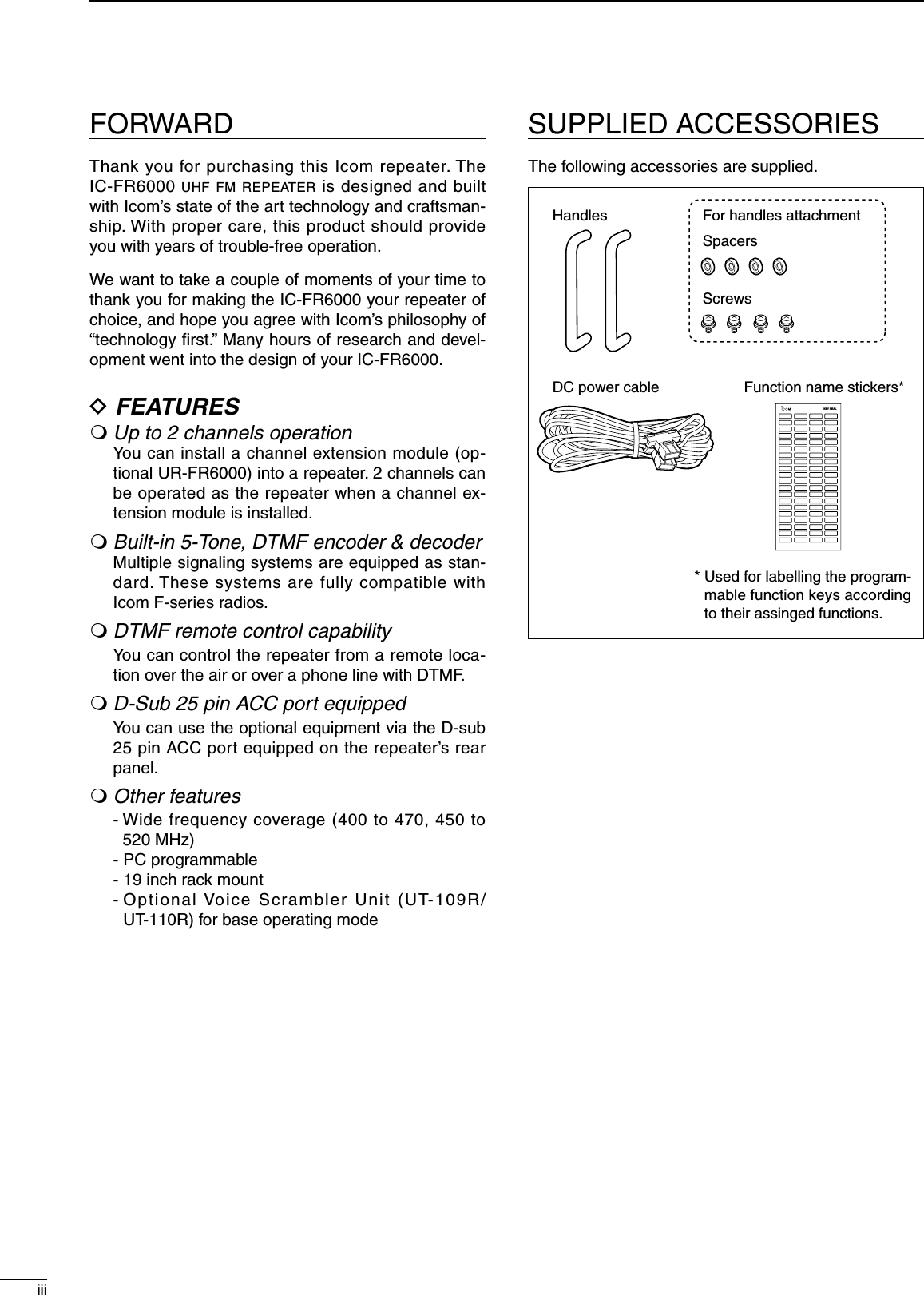
![31PANEL DESCRIPTIOND Accessory connectorq !3!4 @5SpecificationDescriptionPin NamePin No.NCTXDRXDRTSCTSNCGNDMOD INDISC OUTEXT. D/AVCCEXT. A/DNCGNDEXT.I/O 15EXT.I/O 16EXT.I/O 17EXT.I/O 18EXT.I/O 19DATA INEXT.I/O 21AF OUTEXT.I/O 23EXT.I/O 24EXT.I/O 2512345678910111213141516171819202122232425No connectionOutput terminal for serial communication data.Input terminal for serial communication data.Output terminal for request-to-send data.Input terminal for clear-to-send data.No connectionSerial/digital signal groundModulator input from an external terminal unit.Output terminal for AF signals from the AF detector circuit. Output level is fixed, regardless of [AF] control.The desired function can be assigned.*(Default: Null)13.6 V DC outputCustomize A/D input (Not used)No connectionGroundThe desired function can be assigned.* (Default: Null)The desired function can be assigned.*(Default: P0 Monitor Output)The desired function can be assigned.*(Default: Busy Output)The desired function can be assigned.*(Default: Null)The desired function can be assigned.*(Default: EPTT Input)Input terminal for data.The desired function can be assigned.*(Default: Analog Audible Output)The AF detector Output.The desired function can be assigned.*(Default: Mic Mute Output)The desired function can be assigned.*(Default: Null)The desired function can be assigned.*(Default: Mic Hanger Output)———————Input level: 300 mV rmsOutput level: 300 mV rms—Output current: Less than 1 A———+5 V pull up, Active=L+5 V pull up, Active=L+5 V pull up, Active=L+5 V pull up, Active=L+5 V pull up, Active=L—+5 V pull up, Active=L—+5 V pull up, Active=L+5 V pull up, Active=L+5 V pull up, Active=L* The desired function can be assigned using the optional CS-FR5000 cloning software. Ask your dealer for details.](https://usermanual.wiki/ICOM-orporated/306301/User-Guide-905574-Page-8.png)
![n Front panel connectionP0P1P2P3P4SM-25 DESKTOP MICROPHONE (optional)MICROPHONE CONNECTOR (Front panel view)HM-152 HAND MICROPHONE(optional)qiCAUTION: DO NOT short pin 1 to ground as this can damage the internal 8 V regulator. DC voltage is applied to pin 1 for microphone operation. Only Icom micro-phones are recommended.q +8 V DC output (Max. 10 mA)w Output port for PC programminge NCr M PTT (Input port for TX control)t Microphone groundy Microphone inputu Groundi Input port for PC programmingn Rear panel connectionACC CONNECTOR (p. 3)Used for external equipment control.[RX ANT] (p. 4)[TX ANT] (p. 4)SP-22 EXTERNAL SPEAKERR CAUTION! NEVER remove the fuse-holder from the DC power receptacle.Connect a 4 ˘ external speaker.BlackRed20 AfusesDC power supplyAC outletAC cableSuppliedDC power cable13.6 V; at least 20 ABlack_Red+q PushwR When you disconnect the DC power cable, take care no crack of your fingernail.52INSTALLATION AND CONNECTIONS](https://usermanual.wiki/ICOM-orporated/306301/User-Guide-905574-Page-10.png)
![n Receiving and transmittingD Repeater operationAsk your dealer for details of the repeater’s program-ming.➥When the power is turned ON, the [PWR] indicator lights green. (p. 1)➥The [TX] and [BUSY] indicators light simultane-ously while transmitting/receiving a signal. • The [TX] indicator lights red. • The [BUSY] indicator lights green.D Base station operationReceivingq Push [POWER] to turn the power ON.w Set the audio and squelch levels. ➥ Rotate [SELECT]*1 fully counterclockwise in ad-vance. ➥ Rotate [VOLUME] to adjust the audio output level. ➥ Rotate [SELECT]*1 clockwise until the noise disappears.e Push [CH Up]*2 or [CH Down]*2 to select the de-sired channel. • When receiving a signal, the [BUSY] indicator lights green and audio is emitted from the speaker. • Further adjustment of [VOLUME] to a comfortable lis-tening level may be necessary at this point.*1 When the [SQL Level Up/Down] key function is assigned to [SELECT].*2 When the [CH Up]/[CH Down] key functions are as-signed.Transmittingq Take the microphone off hook.w Wait for the channel to become clear.e Push and hold [PTT] to transmit, then speak into the microphone at your normal voice level.r Release [PTT] to receive.IMPORTANT: To maximize the audio quality of the transmitted sig-nal:(1) Pause briefly after pushing [PTT].(2) Hold the microphone 1 to 2 inch (2.5 to 5 cm) from your mouth, then speak into the microphone at a normal voice level.37OPERATION](https://usermanual.wiki/ICOM-orporated/306301/User-Guide-905574-Page-12.png)
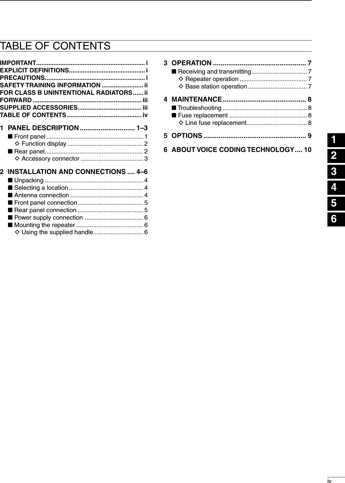
![48MAINTENANCEPROBLEM POSSIBLE CAUSE SOLUTION REF.n TroubleshootingThe following chart is designed to help correct prob-lems which are not equipment malfunctions.If you are unable to locate the cause of a problem or solve it through the use of this chart, contact the near-est Icom Dealer or Service Center.Power does not come on when [POWER] is pushed.No sounds from the speaker.Sensitivity is low and only strong signals are audible.Received signal cannot be understood.Output power is too low.No contact possible with another station.• DC power cable is improperly connected.• Fuse is blown.• Volume level is too low.• The squelch is closed.• The audio mute function is activated.• A selective call or squelch function is acti-vated such as 5 tone call or tone squelch.• The front speaker is set to OFF.• Antenna feedline or the antenna connector has a poor contact or is short-circuited.• Optional voice scrambler is turned OFF.• Scrambler code is not set correctly.• Output power is set to Low.• The other station is using tone squelch.• While in base operating mode, the re-peater is set to duplex.• Re-connect the DC power cable correctly.• Check the cause, then replace the fuse with a spare one. • Rotate [VOLUME] clockwise to obtain a suitable listening level.• While in base operating mode, rotate [SE-LECT] to counterclockwise to open the squelch. (When the [SQL Level Up/Down] key function is assigned to [SELECT].)• Push [MONI] (if assigned) to the audio mute function OFF• Turn the appropriate function OFF.• Turn the front speaker ON using the op-tional CS-FR5000 cloning software. Ask your dealer for details.• Check and re-connect (or replace if neces-sary), the antenna feedline or antenna con-nector.• Turn the optional voice scrambler ON.• Reset the scrambler code.• Push [HIGH/LOW] (if assigned) to select the High power.• Turn the tone squelch function ON.• Set the repeater to simplex, when other transceiver is set to simplex.pgs. 5, 6p. 8p. 7p. 7–––p. 5–––––n Fuse replacementIf a fuse blows or the repeater stops functioning, try to find the source of the problem, and then replace the damaged fuse with a new, rated fuse. CAUTION: DISCONNECT the DC power cable from the repeater. Otherwise, there is danger of electric shock and/or equipment damage.Fuse rating: 20 AUSE the 20 A fuse only.D Line fuse replacement123456789101112131415161718192021](https://usermanual.wiki/ICOM-orporated/306301/User-Guide-905574-Page-13.png)