ICOM orporated 307300 HF/50 MHz TRANSCEIVER User Manual IC 718 Instruction Manual
ICOM Incorporated HF/50 MHz TRANSCEIVER IC 718 Instruction Manual
Contents
- 1. User Manual 1
- 2. User Manual 2
User Manual 1
INSTRUCTION MANUAL
HF/50 MHz TRANSCEIVER
i7600
i
FOREWORD
Thank you for making the IC-7600 your radio of
choice. We hope you agree with Icom’s philosophy of
“technology first.” Many hours of research and devel-
opment went into the design of your IC-7600.
D FEATURES
M Ultimate receiver performance: third-order inter-
cept (IP3) of +30 dBm (HF bands only)
M Built-in Baudot RTTY and PSK modulator/demodu-
lator and direct PC keyboard connection capability
for RTTY and PSK operations without a PC
M High resolution spectrum scope— center frequency
and fixed frequency modes, plus mini-scope dis-
plays
M USB connectors on front and rear panels
M Large LCD with LED backlight
IMPORTANT
READ THIS INSTRUCTION MANUAL
CAREFULLY before attempting to operate the
transceiver.
SAVE THIS INSTRUCTION MANUAL. This
manual contains important safety and operating
instructions for the IC-7600.
EXPLICIT DEFINITIONS
WORD DEFINITION
RWARNING Personal injury, fire hazard or electric
shock may occur.
CAUTION Equipment damage may occur.
NOTE
If disregarded, inconvenience only. No risk
of personal injury, fire or electric shock.
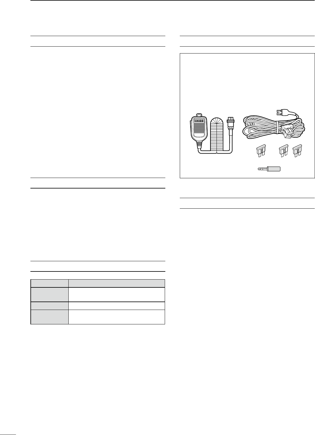
SUPPLIED ACCESSORIES
The transceiver comes with the following accessories.
Qty.
q Hand microphone ............................................ 1
w DC power cable ............................................... 1
e Spare fuse (ATC 5 A) ...................................... 1
r Spare fuse (ATC 30 A) .................................... 2
t 3.5 (d) mm plug ................................................. 1
q
e
t
w
r
FCC INFORMATION
• FOR CLASS B UNINTENTIONAL RADIATORS:
This equipment has been tested and found to comply
with the limits for a Class B digital device, pursuant to
part 15 of the FCC Rules. These limits are designed
to provide reasonable protection against harmful
interference in a residential installation. This equip-
ment generates, uses and can radiate radio frequency
energy and, if not installed and used in accordance
with the instructions, may cause harmful interference
to radio communications. However, there is no guar-
antee that interference will not occur in a particular
installation. If this equipment does cause harmful
interference to radio or television reception, which can
be determined by turning the equipment off and on,
the user is encouraged to try to correct the interfer-
ence by one or more of the following measures:
• Reorient or relocate the receiving antenna.
• Increase the separation between the equipment
and receiver.
• Connect the equipment into an outlet on a
circuit different from that to which the receiver is
connected.
• Consult the dealer or an experienced radio/TV
technician for help.
Icom, Icom Inc. and the Icom logo are registered trademarks of
Icom Incorporated (Japan) in the United States, the United King-
dom, Germany, France, Spain, Russia and/or other countries.
Microsoft, Windows and Windows Vista are either registered trade-
marks or trademarks of Microsoft Corporation in the United States
and/or other countries.
All other products or brands are registered trademarks or trade-
marks of their respective holders.

PRECAUTIONS
R WARNING HIGH RF VOLTAGE! NEVER
attach an antenna or internal antenna connector
during transmission. This may result in an electrical
shock or burn.
R WARNING! NEVER
operate the transceiver
with a headset or other audio accessories at high
volume levels. Hearing experts advise against continu-
ous high volume operation. If you experience a ringing
in your ears, reduce the volume or discontinue use.
R WARNING! Immediately turn the transceiver
power OFF and remove the power cable if it emits an
abnormal odor, sound or smoke. Contact your Icom
dealer or distributor for advice.
R CAUTION! NEVER put the transceiver in
any unstable place (such as on a slanted surface or
vibrated place). This may cause injury and/or damage
to the transceiver.
R CAUTION! NEVER change the internal
settings of the transceiver. This may reduce trans-
ceiver performance and/or damage to the transceiver.
In particular, incorrect settings for transmitter circuits,
such as output power, idling current, etc., might
damage the expensive final devices.
The transceiver warranty does not cover any prob-
lems caused by unauthorized internal adjustment.
R CAUTION! NEVER apply AC power to the
[DC13.8V] socket on the transceiver rear panel. This
could cause a fire or damage the transceiver.
R CAUTION! NEVER apply more than 16 V DC,
such as a 24 V battery, to the [DC13.8V] socket on
the transceiver rear panel. This could cause a fire or
damage the transceiver.
R CAUTION! NEVER
let metal, wire or other
objects protrude into the transceiver or into connectors
on the rear panel. This may result in an electric shock.
R CAUTION! NEVER block any cooling vents
on the top, rear or bottom of the transceiver.
R CAUTION! NEVER expose the transceiver to
rain, snow or any liquids.
R CAUTION! NEVER
install the transceiver in a
place without adequate ventilation. Heat dissipation
may be reduced, and the transceiver may be damaged.
R CAUTION! NEVER operate or touch the trans-
ceiver with wet hands. This may result in an electric
shock or damage to the transceiver.
DO NOT use chemical agents such as benzine
or alcohol when cleaning the IC-7600, as they can
damage the transceiver’s surfaces.
DO NOT push the PTT switch when you don’t actu-
ally desire to transmit.
DO NOT use or place the transceiver in areas with
temperatures below ±0°C (+32°F) or above +50°C
(+122°F).
DO NOT place the transceiver in excessively dusty
environments or in direct sunlight.
DO NOT place the transceiver against walls or
putting anything on top of the transceiver. This may
overheat the transceiver.
Always place unit in a secure place to avoid inadver-
tent use by children.
BE CAREFUL! If you use a linear amplifier, set the
transceiver’s RF output power to less than the linear
amplifier’s maximum input level, otherwise, the linear
amplifier will be damaged.
BE CAREFUL! The heatsink will become hot when
operating the transceiver continuously for long peri-
ods of time.
Use Icom microphones only (supplied or optional).
Other manufacturers’ microphones have different pin
assignments, and connection to the IC-7600 may
damage the transceiver or microphone.
The LCD display may have cosmetic imperfections
that appear as small dark or light spots. This is not a
malfunction or defect, but a normal characteristic of
LCD displays.
During maritime mobile operation, keep the trans-
ceiver and microphone as far away as possible from
the magnetic navigation compass to prevent errone-
ous indications.
Turn the transceiver power OFF and/or disconnect
the DC power cable when you will not use the trans-
ceiver for long period of time.
For U.S.A. only
CAUTION: Changes or modifications to this device,
not expressly approved by Icom Inc., could void your
authority to operate this device under FCC regula-
tions.
i
1
2
3
4
5
6
7
8
9
10
11
12
13
14
15
16
17
18
19
20
21

i
TABLE OF CONTENTS
作成中

i
1
2
3
4
5
6
7
8
9
10
11
12
13
14
15
16
17
18
19
20
21
作成中

TABLE OF CONTENTS
i
作成中

i
1
2
3
4
5
6
7
8
9
10
11
12
13
14
15
16
17
18
19
20
21
作成中
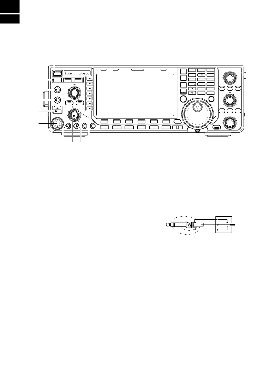
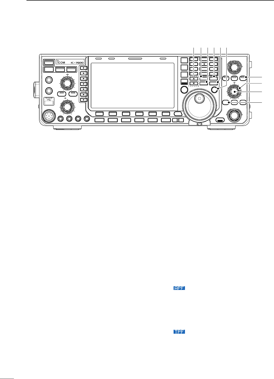
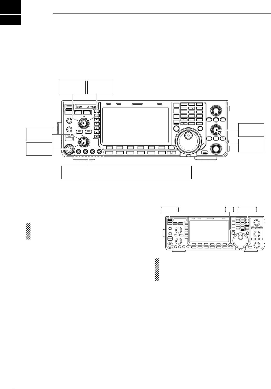
q POWER SWITCH [POWER•TIMER] (p. ??)
While transceiver’s power is OFF:
± Push to turn the transceiver power ON.
• Turn the optional DC power supply ON in advance.
• The indicator on this switch lights green when pow-
ered ON.
While transceiver’s power is ON:
± Push momentarily to toggle the timer function
ON and OFF. (p. ??)
• The indicator on this switch lights red when the timer
function is ON.
± Push and hold for 1 sec. to turn the transceiver
power OFF.
w TRANSMIT SWITCH [TRANSMIT]
Selects transmit or receive.
• The [TX] indicator lights red while transmitting and the
[RX] indicator lights green when the squelch is open.
e HEADPHONE JACK [PHONES]
Accepts standard stereo headphones.
• Output power: 5 mW with an 8 ø load.
• When headphones are connected, the internal speaker
or connected external speaker does not function.
r ELECTRONIC KEYER JACK [ELEC-KEY]
Accepts a paddle to activate the internal electronic
keyer for CW operation. (p. ??)
• You can select internal electronic keyer, bug-key or
straight key operation in keyer CW-key screen. (p. ??)
• A straight key jack is located on the rear panel. See
[KEY] on p. ??.
• Keyer polarity (dot and dash) can be reversed in keyer
CW-key screen. (p. ??)
• A 4-channel memory keyer is available for your conve-
nience. (p. ??)
(dot)
(com)
(dash)
t USB (Universal Serial Bus) CONNECTOR
(A type) [USB] (A) (p. ??)
± Insert USB-Memory* for both reading/storing a
wide variety of the transceiver’s information and
data.
• The indicator above the connectors lights or blinks
when the transceiver reads or writes to the memory
data.
• Unmount operation should be performed before re-
moving the USB-Memory* (p.??).
± Connects a PC keyboard for RTTY and PSK op-
erations.
• USB keyboards* are supported.
*: USB-Memory or USB keyboard is not supplied by
Icom.
N Front panel
TWIN-PBT
RIT/ TX
Ӡ
NOTCH
CW PITCH
VOICE MEMORY
BAL NR
AF RF/SQL
MIC GAIN RF POWER BK-IN DELAY KEY SPEED
TIMER
PHONES
ELEC-KEY
MIC
AUTO
TUNE
GENE F-INP
1.8 3 .5
12
14
5
18
6
7
3
24
8
28
9
50
0
ENT
4
7
10
21
CHANGE
TS
XFC
SPLIT
DUAL
WATCH
MAIN
/
SUB
VFO/ MEMO
MP-W
MW
MP-R
F-
6
F-
5
F-
4
F-
3
F-
2
F-
1
NRNB
PBT-CLR
APF/TPF
NOTCH
POWER
RIT
CLEAR
TX
Ӡ
SPEECH
LOCK
FILTER
REC PLAY
EXIT
/
SET
SSB CW
RTTY
/
PSK
AM/FM
MONITOR
TRANSMIT TUNER
HF/50MHz TRANSCEIVER
LOCKTX RX SPLIT
q
w
e
y
t
r
uio!0
1
1
PANEL DESCRIPTION
y MICROPHONE CONNECTOR [MIC]
Accepts the supplied or optional microphone.
• See p. ?? for appropriate microphones.
• See
p. ?? for microphone connector information.
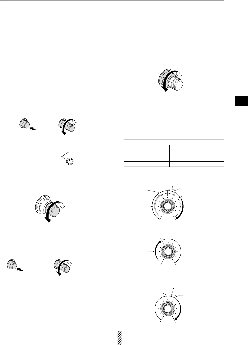
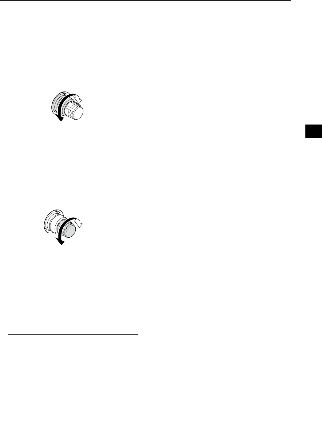
u MIC GAIN CONTROL [MIC GAIN] (p. ??)
Adjusts microphone input gain.
• The transmit audio tone in SSB, AM and FM modes can
be adjusted independently in set mode. (p. ??)
How to set the microphone gain.
Set the [MIC GAIN] control so that the ALC meter
occasionally moves up-scale during normal voice
transmission in SSB, AM or FM mode.
MIC GAIN
Recommended level for
an Icom microphone
Increases
Decreases
Push
i AF CONTROL [AF] (inner control; p. ??)
Varies the audio output level of the speaker or
headphones.
Increases
Decreases
o RF POWER CONTROL [RF PWR] (p. ??)
Continuously varies the RF output power from mini-
mum (2 W*) to maximum (100 W*).
*AM mode: 1 W to 30 W
Increases
max. 100 W
(30 W for AM)
Decreases
min. 2 W
(1 W for AM)
Push
!0 RF GAIN CONTROL/SQUELCH CONTROL
[RF/SQL] (outer control; p. ??)
Adjusts the RF gain and squelch threshold level.
The squelch removes noise output from the speaker
(closed condition) when no signal is received.
• The squelch is particularly effective for FM. It is also
available for other modes.
• 12 to 1 o’clock position is recommended for any setting
of the [RF/SQL] control.
• The control can be set as ‘Auto’ (RF gain control in
SSB, CW and RTTY; squelch control in AM and FM)
or squelch control (RF gain is fixed at maximum) in set
mode as follows. (p. ??)
MODE SET MODE SETTING
AUTO SQL RF GAIN + SQL
SSB, CW
RTTY/PSK RF GAIN SQL RF GAIN + SQL
AM, FM SQL SQL RF GAIN + SQL
• When setting as RF gain/squelch control
Maximum
RF gain
S-meter
squelch
Noise squelch (FM mode)
Squelch is
open.
RF gain
adjustable
range
Recommended level
• When functioning as RF gain control
(Squelch is fixed open; SSB, CW, RTTY only)
Minimum RF gain
Adjustable
range
Maximum
RF gain
• When functioning as squelch control
(RF gain is fixed at maximum.)
Squelch is
open.
S-meter
squelch
S-meter squelch
threshold
Noise squelch
threshold
(FM mode)
Shallow Deep
Noise squelch (FM mode)
While rotating the RF gain control, noise may be
heard. This comes from the DSP unit and does not
indicate an equipment malfunction. 2
1
PANEL DESCRIPTION
1
2
3
4
5
6
7
8
9
10
11
12
13
14
15
16
17
18
19
20
21
!1 BREAK-IN DELAY CONTROL
[BK-IN DELAY] (p. ??)
Adjusts the transmit-to-receive switching delay time
for CW semi-break-in operations.
Push
Short delay
for high speed
keying (2 dot)
Long delay for
slow speed
keying (13 dot)
!2 ELECTRONIC CW KEYER SPEED CONTROL
[KEY SPEED] (p. ??)
Adjusts keying speed for the internal electronic CW
keyer from 6 wpm (min.) to 48 wpm (max.).
Push Slow
(6 wpm)
Fast
(48 wpm)
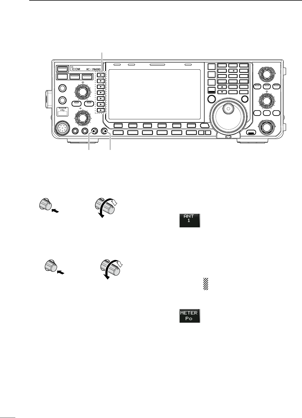
!3 MULTI-FUNCTION SWITCHES
Push to select the functions indicated in the LCD
display to the right of these switches.
• Functions vary depending on the operating condition.
MF1 (MULTI-FUNCTION 1 SWITCH)
ANT SWITCH (ANT)
± Selects the antenna connector be-
tween ANT1 and ANT2 when pushed.
(p. ??)
± Turns the [RX ANT] (receive antenna)
ON and OFF when pushed and held
for 1 sec.
• When the receive antenna is activated,
the antenna which is connected to the
[ANT1] or [ANT2] is used for transmis-
sion only.
When a transverter is in use, this [ANT]
does not function and ‘TRV’ appears.
MF2 (MULTI-FUNCTION 2 SWITCH)
METER SWITCH (METER)
± Selects RF power (Po), SWR, ALC,
COMP, VD or ID metering during trans-
mit. (p. ??)
± Switches the multi-function digital
meter ON and OFF when pushed and
held for 1 sec. (p. ??)
N Front panel (continued)
TWIN-PBT
RIT/ TX
Ӡ
NOTCH
CW PITCH
VOICE MEMORY
BAL NR
AF RF/SQL
MIC GAIN RF POWER BK-IN DELAY KEY SPEED
TIMER
PHONES
ELEC-KEY
MIC
AUTO
TUNE
M.SCOPE
GENE F-INP
1.8 3 .5
12
14
5
18
6
7
3
24
8
28
9
50
0
ENT
4
7
10
21
CHANGE
TS
XFC
SPLIT
DUAL
WATCH
MAIN
/
SUB
VFO/ MEMO
MP-W
MW
MP-R
F-
6
F-
5
F-
4
F-
3
F-
2
F-
1
NRNB
PBT-CLR
APF/TPF
NOTCH
POWER
RIT
CLEAR
TX
Ӡ
SPEECH
LOCK
FILTER
REC PLAY
EXIT
/
SET
SSB CW
RTTY
/
PSK
AM/FM
MONITOR
TRANSMIT TUNER
HF/50MHz TRANSCEIVER
LOCKTX RX SPLIT
!1 !2
!3
3
1PANEL DESCRIPTION
MF3 (MULTI-FUNCTION 3 SWITCH)
P.AMP SWITCH (P.AMP)
± Selects one of 2 receive RF preamps
or bypasses them. (p. ??)
• “P. AMP1” activates 10 dB preamp.
• “ P. AMP2” activates 16 dB high-gain pre-
amp.
• “P. AMP OFF” can also be selected.
± Turns the preamp function OFF when
pushed and held for 1 sec. (p. ??)
What is the preamp?
The preamp amplifies signals in the front end to im-
prove S/N ratio and sensitivity. Select “P. AMP1” or
“P. AMP2” when receiving weak signals.
MF4 (MULTI-FUNCTION 4 SWITCH)
ATT SWITCH (ATT)
± Selects 6 dB, 12 dB or 18 dB attenua-
tor when pushed. (p. ??)
• “ATT OFF” can also be selected.
± Turns the attenuator function OFF
when pushed and held for 1 sec.
(p. ??)
What is the attenuator?
The attenuator prevents a desired signal from being
distorted when very strong signals are near the de-
sired frequency, or when very strong electromag-
netic fields, such as from a broadcasting station,
are near your location.
MF5 (MULTI-FUNCTION 5 SWITCH)
AGC SWITCH (AGC)
± Activates and selects fast, middle or
slow AGC time constant when pushed.
(p. ??)
• In FM mode, only “FAST” is available.
± Enters the AGC set mode when
pushed and held for 1 sec. (p. ??)
AGC time constant can be set between
0.1 to 8.0 sec. (depends on mode), or
turned OFF. When AGC is “OFF,” the S-
meter does not function.
What is the AGC?
The AGC controls receiver gain to produce a con-
stant audio output level, even when the received
signal strength varies dramatically. Select “FAST”
for tuning and then select “MID” or “SLOW” depend-
ing on the receiving condition.
MF6 (MULTI-FUNCTION 6 SWITCH)
VOX SWITCH (VOX)
± Push to turn the VOX function ON and
OFF during SSB, AM and FM mode
operation. (p. ??)
± Push and hold for 1 sec. to enter VOX
set mode. (p. ??)
What is the VOX function?
The VOX function (voice operated transmission)
activates transmission without pushing the trans-
mit switch or PTT switch when you speak into the
microphone; then automatically returns to receive
when you stop speaking.
BK-IN SWITCH (BK-IN)
± Selects semi break-in, full break-in op-
eration, or turns the break-in operation
OFF when pushed in CW mode.
(p. ??)
What is the break-in function?
The break-in function switches transmit and receive
with CW keying. Full break-in function (QSK) can
monitor the receive signal during keying.
MF7 (MULTI-FUNCTION 7 SWITCH)
COMP SWITCH (COMP)
± Turns the speech compressor ON and
OFF in SSB mode. (p. ??)
± Switches the narrow, middle or wide
compression when pushed and held
for 1 sec.
What is the speech compressor?
The speech compressor compresses the transmit-
ter audio input to increase the average audio output
level, to increase talk power. This function is effec-
tive for long-distance communication or when prop-
agation conditions are poor.
1⁄4 SWITCH (1⁄4)
± Turns the 1⁄4 speed tuning function ON
and OFF in SSB data, CW, RTTY and
PSK modes. (p. ??)
•
1⁄4 function sets dial rotation to 1⁄4 of nor-
mal speed for fine tuning.
TONE SWITCH (TONE)
± Switches between the tone encoder,
tone squelch function and no-tone
operation when pushed in FM mode.
(pgs. ??, ??)
± Enters the tone set mode when pushed
and held for 1 sec. in FM mode.
(pgs. ??, ??)
4
1
PANEL DESCRIPTION
1
2
3
4
5
6
7
8
9
10
11
12
13
14
15
16
17
18
19
20
21
!4 NOISE REDUCTION SWITCH [NR] (p. ??)
Push to switch DSP noise reduction ON and OFF.
• The indicator on this switch lights green when the func-
tion is activated.
!5 MONITOR SWITCH [MONITOR] (p. ??)
Monitors your transmitted IF signal.
• The CW sidetone functions regardless of the [MONI-
TOR] switch setting in CW mode.
• The indicator on this switch lights green while the func-
tion is activated.
!6 ANTENNA TUNER SWITCH [TUNER] (p. ??)
± Turns the internal antenna tuner ON and OFF
(bypass) when pushed momentarily.
• The indicator on this switch lights green when the
tuner is turned ON, goes off when tuner is turned
OFF (bypassed).
± Tunes the antenna tuner manually when pushed
and held for 1 sec.
• The indicator on this switch blinks red during manual
tuning.
• When the tuner cannot tune the antenna, the tuning
circuit is bypassed automatically after 20 sec.
!7 NOISE REDUCTION LEVEL CONTROL [NR]
(outer control; p. ??)
Adjusts the DSP noise reduction level when the
noise reduction function is in use. Set for maximum
readability.
• To use this control, push [NR] (!4) in advance.
Decreases
Increases
!8 BALANCE CONTROL [BAL] (inner control; p. ??)
Adjusts the audio output balance between main and
sub readout frequencies while in dualwatch.
Increases main
readout gain
Increases sub
readout gain
!9 NOISE BLANKER SWITCH [NB] (p. ??)
± Switches the noise blanker ON and OFF when
pushed. The noise blanker reduces pulse-type
noise such as that generated by automobile igni-
tion systems. This function cannot be used in FM
mode, or on non-pulse-type noise.
• The indicator on this switch lights green while the
function is activated.
± Enters the noise blanker level set mode when
pushed and held for 1 sec.
@0 LCD FUNCTION SWITCHES [F-1] to [F-6]
Push to select the function indicated in the LCD dis-
play above these switches.
• Functions vary depending on the operating condition.
N Front panel (continued)
TWIN-PBT
RIT/ TX
Ӡ
NOTCH
CW PITCH
VOICE MEMORY
BAL NR
AF RF/SQL
MIC GAIN RF POWER BK-IN DELAY KEY SPEED
TIMER
PHONES
ELEC-KEY
MIC
AUTO
TUNE
GENE F-INP
1.8 3 .5
12
14
5
18
6
7
3
24
8
28
9
50
0
ENT
4
7
10
21
CHANGE
TS
XFC
SPLIT
DUAL
WATCH
MAIN
/
SUB
M.SCOPE
VFO/ MEMO
MP-W
MW
MP-R
F-
6
F-
5
F-
4
F-
3
F-
2
F-
1
NRNB
PBT-CLR
APF/TPF
NOTCH
POWER
RIT
CLEAR
TX
Ӡ
SPEECH
LOCK
FILTER
REC PLAY
EXIT
/
SET
SSB CW
RTTY
/
PSK
AM/FM
MONITOR
TRANSMIT TUNER
HF/50MHz TRANSCEIVER
LOCKTX RX SPLIT
!4!5!6
!7
!9
!8
@
0
@
1
@
2
@
3
@
7
@
8
@
9
@
6
@
5
@
4
5
1PANEL DESCRIPTION

@1 MODE SWITCHES
Selects the desired mode. (p. ??)
• Announces the selected mode via the speech synthe-
sizer. (p. ??)
[SSB]
± Selects USB and LSB modes alternately when
pushed.
± Selects SSB data mode (USB-D, LSB-D) when
pushed and held for 1 sec. in SSB mode.
• In SSB data mode, push to return to SSB mode.
± Switches D1, D2 and D3 when pushed and held
for 1 sec. in SSB data mode.
[CW]
Selects CW and CW-R (CW reverse) modes alter-
nately when pushed.
[RTTY/PSK]
± Selects RTTY and PSK modes alternately when
pushed.
± Switches RTTY and RTTY-R (RTTY reverse)
mode when pushed and held for 1 sec. in RTTY
mode.
± Switches PSK and PSK-R (PSK reverse) mode
when pushed and held for 1 sec. in PSK mode.
[AM/FM]
± Selects AM and FM modes alternately.
± Selects AM or FM data mode (AM-D/FM-D)
when pushed and held for 1 sec. in AM or FM
mode, respectively.
• In AM or FM data mode, push to return to AM or FM
mode, respectively.
± Switches D1, D2 and D3 when pushed and held
for 1 sec. in AM or FM data mode.
@2 FILTER SWITCH [FILTER] (p. ??)
± Push to select one of 3 IF filter settings.
± Push and hold for 1 sec. to display the filter set
screen.
@3 EXIT/SET SWITCH [EXIT/SET]
± Push to exit, or return to the previous screen in-
dication during spectrum scope, memory, scan
or set mode screen display.
± Push and hold for 1 sec. to display the set mode
menu screen.
@4 VOICE MEMORY RECORD SWITCH [REC]
(p. ??)
± Push to record the previous received signal for
the preset time period.
• The preset time period can be set in voice set mode.
(p. ??)
± Push and hold for 1 sec. to record the received
signal until the recording is cancelled.
• Push this switch momentarily to stop recording.
• The memory records the latest 30 sec. of audio.
@5 VOICE MEMORY PLAYBACK SWITCH [PLAY]
(p. ??)
± Push to playback the previously recorded audio
for the preset time period.
± Push and hold for 1 sec. to playback all of the
previously recorded audio.
@6 AUTOMATIC TUNING SWITCH [AUTO TUNE]
(p. ??)
Turns the automatic tuning function ON and OFF in
CW and AM modes.
IMPORTANT!
When receiving a weak signal, or receiving a sig-
nal with interference, the automatic tuning func-
tion may tune the receiver to an undesired signal.
@7 MAIN DIAL
Changes the displayed frequency, selects set mode
setting, etc.
@8 SPEECH/LOCK SWITCH [SPEECH/LOCK]
± Push to announce the S-meter indication and the
selected frequency. (p. ??)
• The parameters to be announced can be selected in
the others set mode. (p. ??)
± Push and hold for 1 sec. to turn the dial lock
function ON and OFF. (p. ??)
• The dial lock function electronically locks the main
dial.
• The lock indicator lights while the dial lock function is
activated.
NOTE: The [SPEECH/LOCK] switch operation to
activate the voice synthesizer or the dial lock
functions can be replaced in others set mode
screen. (p. ??)
@9 RIT/∂TX CONTROL [RIT/∂TX] (pgs. ??, ??)
Shifts the receive and/or transmit frequency with-
out changing the transmit and/or receive frequency
shown on the main VFO while the RIT and/or ∂TX
functions are/is ON.
• Rotate the control clockwise to increase the frequency,
or rotate the control counterclockwise to decrease the
frequency. The RIT or ∂TX functions must be ON.
• The shift frequency range is ±9.999 kHz in 1 Hz steps
(or ±9.99 kHz in 10 Hz steps).
Low shift
High shift
6
1
PANEL DESCRIPTION
1
2
3
4
5
6
7
8
9
10
11
12
13
14
15
16
17
18
19
20
21
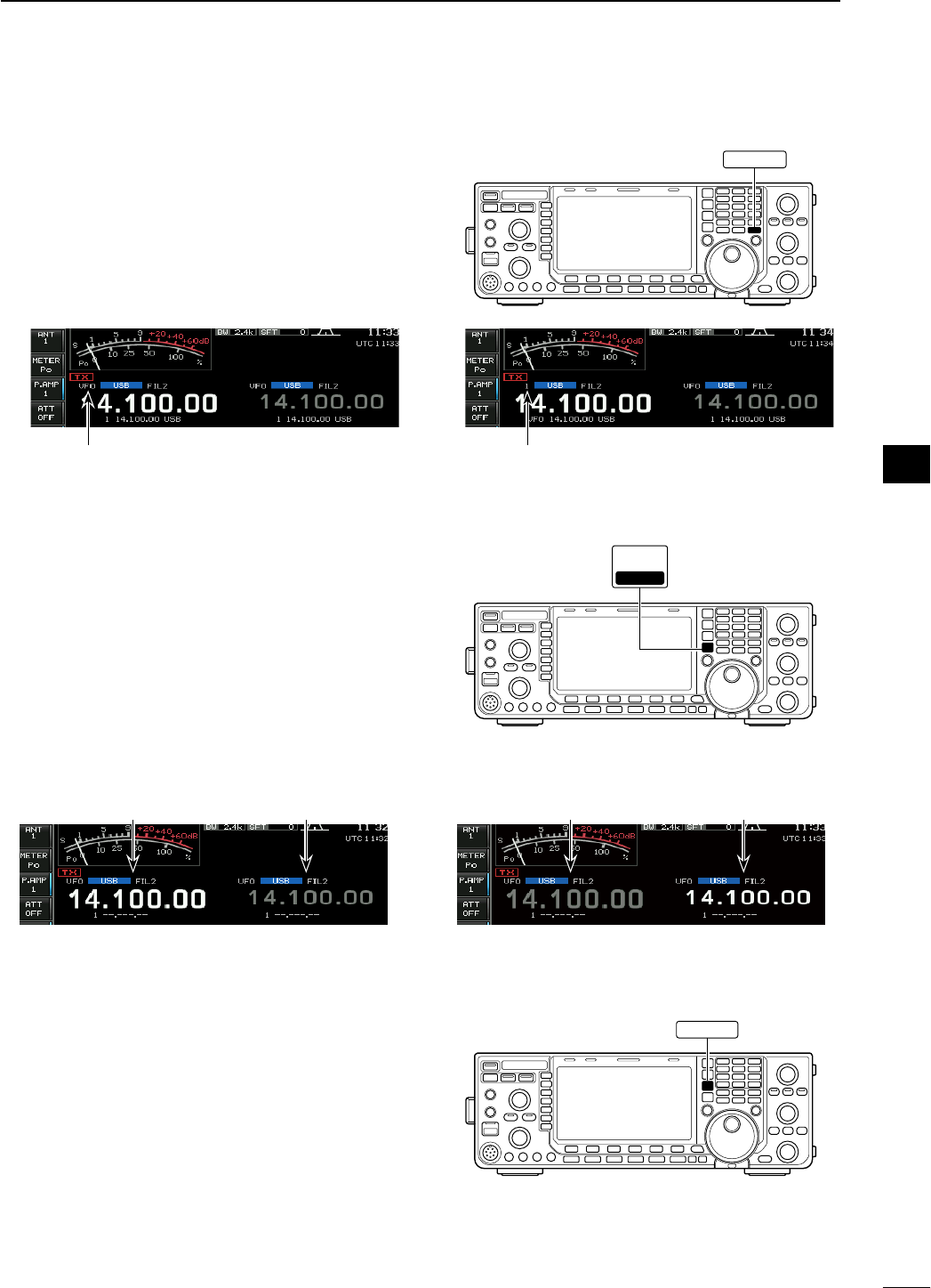
#0 TRANSMIT INDICATOR [TX]
Lights red while transmitting.
#1 RECEIVE INDICATOR [RX]
Lights green while receiving a signal and when the
squelch is open.
#2 LCD FUNCTION DISPLAY (p. ??)
Shows the operating frequency, function switch
menus, spectrum scope screen, memory list
screen, set mode settings, etc.
#3 SPLIT OPERATION INDICATOR [SPLIT]
Lights during split frequency operation.
#4 MAIN/SUB CHANGE SWITCH [CHANGE]
± Switches the frequency and selected memory
channel between main and sub readouts when
pushed.
• Switches between transmit frequency and receive
frequency when the split frequency function is ON.
(p. ??)
± Equalizes the sub readout frequency to the main
readout frequency when pushed and held for 1
sec.
#5 LOCK INDICATOR [LOCK] (p. ??)
Lights when the dial lock function is activated.
#6 DUALWATCH SWITCH [DUALWATCH] (p. ??)
± Push to turn the dualwatch function ON and
OFF.
• “ ” appears when the dualwatch function
is in use.
± Push and hold for 1 sec. to turn the dualwatch
function ON and equalizes the sub readout fre-
quency to the main readout. (Quick dualwatch
function)
• The quick dualwatch function can be turned OFF in
others set mode. (p. ??)
#7 SPLIT SWITCH [SPLIT] (p. ??)
± Push to turn the split function ON and OFF.
• “ ” appears when the split function is in
use.
± Push and hold for 1 sec. to activate the quick
split function.
• The split function ON and equalize the sub readout
frequency to the main readout and sets the sub read-
out for frequency input in non-FM modes. (p. ??)
• The offset frequency is shifted from the selected VFO
frequency in FM mode. (p. ??)
• The quick split function can be turned OFF in others
set mode. (p. ??)
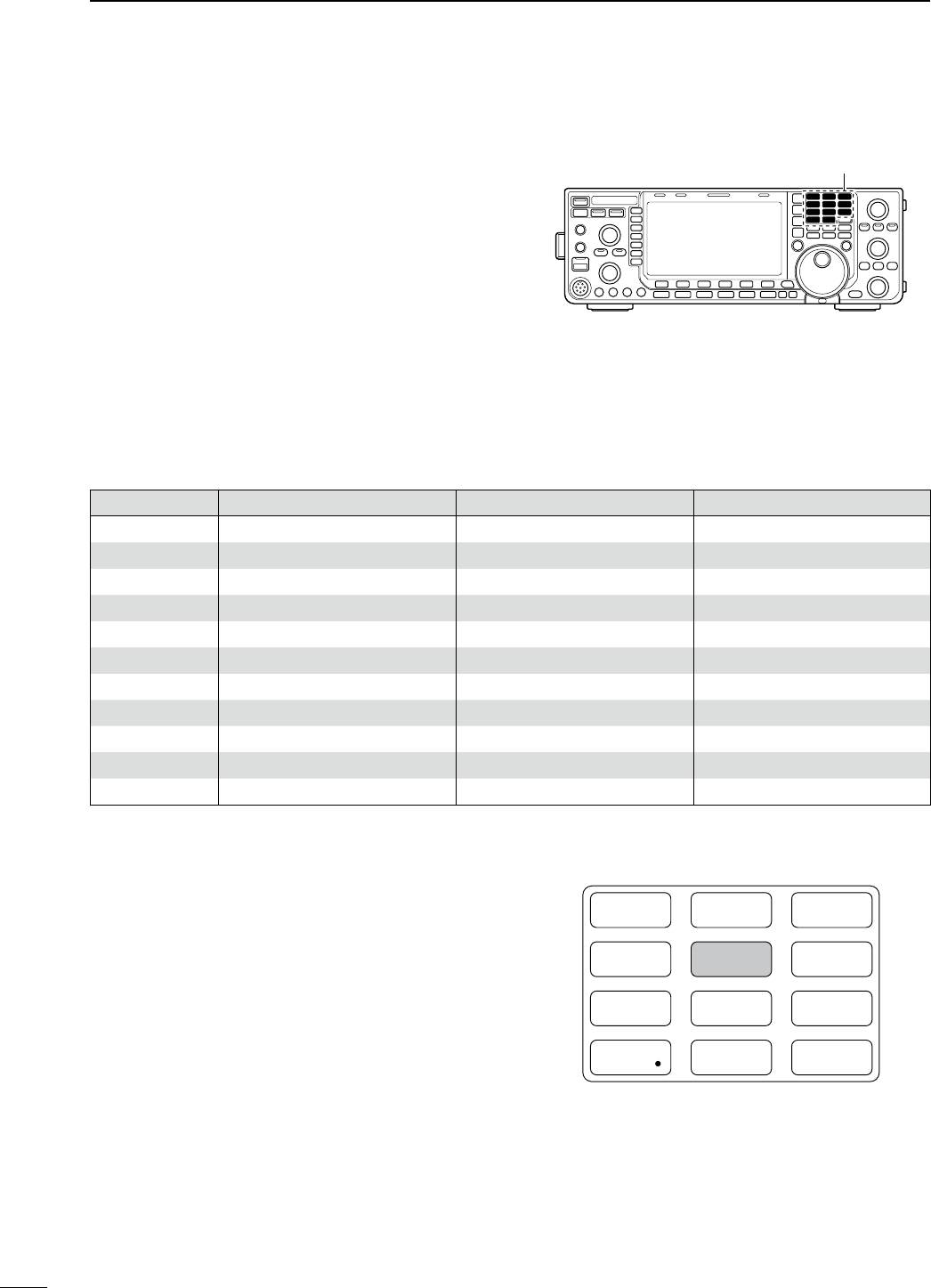
#8 KEYPAD
± Pushing a key selects the operating band. (p. ??)
• [GEN •] selects the general coverage band.
± Pushing the same key 2 or 3 times calls up other
stacked frequencies in the band.
(p. ??)
• Icom’s triple band stacking register memorizes 3 fre-
quencies in each band.
± After pushing [F-INP ENT], push a key on the
keypad to enter a numeric frequency. After en-
tering, push [F-INP ENT] to select the desired
frequency directly
(p. ??)
• e.g. to enter 14.195 MHz;
Push [F-INP ENT] [1] [4] [•] [1] [9] [5] [F-INP ENT].
± After pushing [F-INP ENT], push a key on the
keypad to enter a memory channel. after enter-
ing, push [∫]/[√] to select the desired memory
channel directly.
(p. ??)
#9 PBT CLEAR SWITCH [PBT-CLR] (p. ??)
Push and hold for 1 sec. to clear the PBT settings.
• The indicator on this switch lights green when PBT is in
use.
N Front panel (continued)
TWIN-PBT
RIT/ TX
Ӡ
NOTCH
CW PITCH
VOICE MEMORY
BAL NR
AF RF/SQL
MIC GAIN RF POWER BK-IN DELAY KEY SPEED
TIMER
PHONES
ELEC-KEY
MIC
AUTO
TUNE
GENE F-INP
1.8 3 .5
12
14
5
18
6
7
3
24
8
28
9
50
0
ENT
4
7
10
21
CHANGE
TS
XFC
SPLIT
DUAL
WATCH
MAIN
/
SUB
M.SCOPE
VFO/ MEMO
MP-W
MW
MP-R
F-
6
F-
5
F-
4
F-
3
F-
2
F-
1
NRNB
PBT-CLR
APF/TPF
NOTCH
POWER
RIT
CLEAR
TX
Ӡ
SPEECH
LOCK
FILTER
REC PLAY
EXIT
/
SET
SSB CW
RTTY
/
PSK
AM/FM
MONITOR
TRANSMIT TUNER
HF/50MHz TRANSCEIVER
LOCKTX RX SPLIT
$2
$3
#0 #5#4 #6 #7 #8 $0#9#3#2#1
$1
$4$5
7
1PANEL DESCRIPTION
$0 PASSBAND TUNING CONTROLS [TWIN-PBT]
(p. ??)
Adjusts the receiver’s IF filter “passband width” via
the DSP.
• Passband width and shift frequency are displayed in the
multi-function display.
• Push and hold [PBT-CLR] for 1 sec. to clear the PBT
settings.
• Adjustment range is set to half of the IF filter passband
width. 25 Hz steps and 100 Hz steps are available.
What is the PBT control?
The PBT function electronically modifies the IF passband
width to reject interference. This transceiver uses the DSP
circuit for the PBT function.
PBT1
PBT2
–+
Low cutHigh cut Center
$1 NOTCH SWITCH [NOTCH] (p. ??)
± Switches the notch function between auto, man-
ual and OFF in SSB and AM modes.
± Turns the manual notch function ON and OFF
when pushed in CW, RTTY and PSK mode.
± Turns the auto notch function ON and OFF when
pushed in FM mode.
• “ ” appears when manual notch is in use.
• “ ” appears when auto notch is in use.
• No indicator appears when the notch function is not
in use.
± Push and hold for 1 sec. to switch the manual
notch characteristics from wide, middle and nar-
row when manual notch function is activated.
• The indicator on this switch lights green when the
function is activated.
What is the notch function?
The notch function is a narrow filter that eliminates un-
wanted CW or AM carrier tones while preserving the de-
sired voice signal. The DSP circuit automatically adjusts
the notch frequency to effectively eliminate unwanted
tones.
$2 ∂TX SWITCH [∂TX] (p. ??)
± Push to turn the ∂TX function ON and OFF.
• Use [RIT/∂TX] control to vary the ∂TX frequency.
± Push and hold for 1 sec. to add the ∂TX shift
frequency to the operating frequency.
What is the ∂TX function?
∂TX shifts the transmit frequency without shifting the re-
ceive frequency. This is useful for simple split frequency
operation in CW, etc.
$3 CLEAR SWITCH [CLEAR] (pgs. ??, ??)
Push or push and hold for 1 sec.* to clear the RIT/
∂TX shift frequency.
* Depending on the quick RIT/∂TX clear function setting
(p. ??).
$4 TRANSMIT FREQUENCY CHECK SWITCH
[XFC] (p. ??)
Monitors the transmit frequency (including ∂TX fre-
quency offset) when pushed and held during split
frequency operation.
• While pushing and holding this switch, the transmit
frequency can be changed with the main dial, keypad,
memo pad or [∫]/[√] switches.
• When the split lock function is turned ON, pushing [XFC]
cancels the dial lock function. (p. ??)
$5 MAIN/SUB•M.SCOPE SWITCH
[MAIN/SUB•M.SCOPE]
± Push to select access to the main or sub read-
out. (p. ??)
• The selected readout frequency is displayed clearly.
The sub readout functions only during split operation
or dualwatch.
± Push and hold for 1 sec. to turn the mini spec-
trum scope screen indication ON and OFF.
(p. ??)
• The mini spectrum scope screen can be indicated
with another screen, such as memory, set mode
screen, simultaneously.
8
1
PANEL DESCRIPTION
1
2
3
4
5
6
7
8
9
10
11
12
13
14
15
16
17
18
19
20
21
$6 MEMORY UP/DOWN SWITCHES [∫]/[√] (p. ??)
±
Push to select the desired memory channel.
• Memory channels can be selected both in VFO and
memory modes.
±
Push to select the desired memory channel di-
rectly after pushing [F-INP ENT] and a memory
channel number.
$7 MEMO PAD-WRITE SWITCH [MP-W] (p. ??)
Programs the displayed readout frequency and op-
erating mode into a memo pad.
• The 5 most recent entries remain in memo pads.
• The memo pad capacity can be expanded from 5 to 10
in others set mode. (p. ??)
$8 MEMORY WRITE SWITCH [MW] (p. ??)
Stores the selected readout frequency and operat-
ing mode into the displayed memory channel when
pushed and held for 1 sec.
• This function is available both in VFO and memory
modes.
$9 MEMO PAD-READ SWITCH [MP-R] (p. ??)
Each push calls up a frequency and operating
mode in a memo pad. The 5 (or 10) most recently
programmed frequencies and operating modes can
be recalled, starting from the most recent.
• The memo pad capacity can be expanded from 5 to 10
in others set mode. (p. ??)
%0 VFO/MEMORY SWITCH [VFO/MEMO]
± Switches the selected readout operating mode
between the VFO and memory when pushed.
(pgs. ??, ??)
± Transfers the memory contents to VFO when
pushed and held for 1 sec. (p. ??)
%1 QUICK TUNING SWITCH [TS]
± Turns the quick tuning step ON and OFF. (p. ??)
• While the quick tuning indicator, “Z,” is displayed
above the frequency indication, the frequency can be
changed in programmed kHz steps.
• 0.1, 1, 5, 9, 10, 12.5, 20 and 25 kHz steps are avail-
able for each operating mode independently.
± When the quick tuning step is ON, push and hold
for 1 sec. to enter quick tuning step set mode.
(p. ??)
± When the quick tuning step is OFF, push and
hold for 1 sec. to turn the 1 Hz tuning step ON
and OFF. (p. ??)
%2 AUDIO PEAK FILTER/TWIN PEAK FILTER
SWITCH [APF/TPF]
During CW mode operation (p. ??)
± Push to turn the audio peak filter ON and OFF.
• “ ” appears when audio peak filter is in use.
± When the audio peak filter is ON, push and hold
for 1 sec. to select the APF passband width from
WIDE, MID and NAR or from 320, 160 and 80 Hz
depending on APF type setting.
During RTTY mode operation (p. ??)
± Push to turn the twin peak filter ON and OFF.
• “ ” appears when twin peak filter is in use.
• The indicator on this switch lights green when the
function is activated.
N Front panel (continued)
TWIN-PBT
RIT/ TX
Ӡ
NOTCH
CW PITCH
VOICE MEMORY
BAL NR
AF RF/SQL
MIC GAIN RF POWER BK-IN DELAY KEY SPEED
TIMER
PHONES
ELEC-KEY
MIC
AUTO
TUNE
GENE F-INP
1.8 3 .5
12
14
5
18
6
7
3
24
8
28
9
50
0
ENT
4
7
10
21
CHANGE
TS
XFC
SPLIT
DUAL
WATCH
MAIN
/
SUB
M.SCOPE
VFO/ MEMO
MP-W
MW
MP-R
F-
6
F-
5
F-
4
F-
3
F-
2
F-
1
NRNB
PBT-CLR
APF/TPF
NOTCH
POWER
RIT
CLEAR
TX
Ӡ
SPEECH
LOCK
FILTER
REC PLAY
EXIT
/
SET
SSB CW
RTTY
/
PSK
AM/FM
MONITOR
TRANSMIT TUNER
HF/50MHz TRANSCEIVER
LOCKTX RX SPLIT
$6
%2
$7 $8 $9 %0 %1
%3
%4
%5
9
1PANEL DESCRIPTION
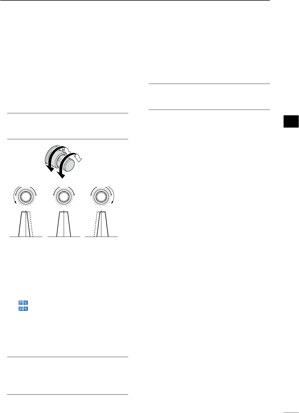
%3 CW PITCH CONTROL [CW PITCH]
(outer control; p. ??)
Shifts the received CW audio pitch and the CW
side tone pitch without changing the operating fre-
quency.
Lower frequency
Higher frequency
%4 MANUAL NOTCH FILTER CONTROL [NOTCH]
(inner control; p. ??)
Varies the notch frequency of the manual notch fil-
ter to reject an interfering signal while the manual
notch function is ON.
• Notch filter center frequency:
LSB : –1040 Hz to 4060 Hz
USB : –1060 Hz to 4040 Hz
CW : CW pitch freq. –2540 Hz to CW pitch freq.
2540 Hz
AM : –5100 Hz to 5100 Hz
Lower frequency
Higher frequency
%5 RIT SWITCH [RIT] (p. ??)
± Push to turn the RIT function ON and OFF.
• Use [RIT/∂TX] control to vary the RIT frequency.
± Push and hold for 1 sec. to add the RIT shift fre-
quency to the operating frequency.
What is the RIT function?
The RIT (Receiver Incremental Tuning) shifts the receive
frequency without shifting the transmit frequency.
This is useful for fine tuning stations calling you off-fre-
quency or when you prefer to listen to slightly different-
sounding voice characteristics, etc.
10
1
PANEL DESCRIPTION
1
2
3
4
5
6
7
8
9
10
11
12
13
14
15
16
17
18
19
20
21
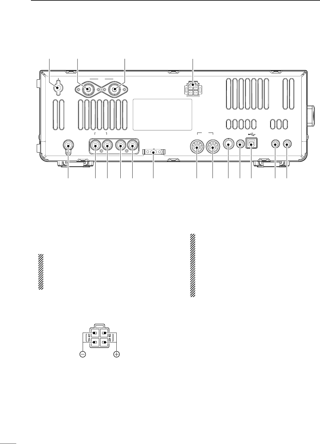
q GROUND TERMINAL [GND] (p. ??)
Connect this terminal to a ground to prevent electri-
cal shocks, TVI, BCI and other problems.
w ANTENNA CONNECTOR 1 [ANT1]
e ANTENNA CONNECTOR 2 [ANT2] (pgs. ??, ??)
Accept a 50 ø antenna with a PL-259 plug connec-
tor.
When using an optional AH-4 HF/50 MHz AUTO-
MATIC ANTENNA TUNER, connect it to the [ANT1]
connector. The internal antenna tuner activates
for [ANT2] and deactivates for [ANT1] when con-
necting the AH-4.
r DC POWER SOCKET [DC 13.8V] (p. ??)
Accepts 13.8 V DC through the supplied DC power
cable.
Rear panel view
t
EXTERNAL SPEAKER JACK [EXT-SP]
(p. ??)
Connects an external speaker (4–8 ø), if desired.
y CI-V REMOTE CONTROL JACK [REMOTE]
(pgs. ??, ??)
± Connects a PC via the optional CT-17 CI-V LEVEL
CONVERTER for external control of the transceiver.
± Used for transceive operation with another Icom
CI-V transceiver or receiver.
u USB (Universal Serial Bus) CONNECTOR (B type)
[USB] (B)
Connect an USB cable to be used for the modula-
tion input (p. ??), the transceiver operation with PC
and the received audio import to the PC.
CAUTION:
For Windows® XP/2000:
NEVER install the USB driver into the PC before
connecting the transceiver and PC using with an
USB cable.
For Windows Vista™:
NEVER connect a PC using with an USB cable
until the USB driver installation has been com-
pleted.
About the USB driver:
Icom HP (http://www.icom.co.jp/world/support/
index.html) gives the USB driver and the installa-
tion guide download service.
The following items are required:
PC
• Microsoft® Windows® XP/2000 or
Microsoft® Windows Vista™ installed
• With USB port
Other items
• USB cable (third party’s)
• PC software
About the modulation input:
Select “USB” in the ACC set mode item ‘DATA OFF
MOD,’ ‘DATA1 MOD,’ ‘DATA2 MOD’ or ‘DATA3 MOD.’
And the modulation input level from USB jack can
be set in the ACC set mode item ‘USB MOD Level.’
(p. ??)
N Rear panel
12ANT DC 13.8V
X-VERTER
RX-ANT
ACC
TUNER
IN OUT ALC SEND KEY
12
METER
REMOTE EXT
-
SP
qw re
tyo!0!1!2!7 !6 !5 !4 !3 iu
11
1PANEL DESCRIPTION
i METER JACK [METER] (p. ??)
Outputs a signal showing received signal strength,
transmit output power, VSWR, ALC, speech com-
pression, VD or ID level for external meter indica-
tion.
o STRAIGHT KEY JACK [KEY] (p. ??)
Accepts a straight key or external electronic keyer
with 1⁄4 inch standard plug.
• [ELEC-KEY] on the front panel can be used for a
straight key or external electronic keyer. Deactivate the
internal electronic keyer in keyer set mode. (p. ??)
(+)
(_)
!0 ACCESSORY SOCKET 1 [ACC 1]
!1 ACCESSORY SOCKET 2 [ACC 2]
Enable connection of external equipment such as
a linear amplifier, an automatic antenna selector/
tuner, a TNC for data communications, etc.
• See p. ?? for socket information.
!2 TUNER CONTROL SOCKET [TUNER] (p. ??)
Accepts the control cable from an optional AH-4
HF/50 MHz AUTOMATIC ANTENNA TUNER.
!3 SEND CONTROL JACK [SEND] (p. ??)
Connects to ground when transmitting to control an
external unit, such as a non-Icom linear amplifier.
NOTE: T/R control voltage and current must be
lower than 16 V DC/0.5 A (or 250 V AC, 200 mA
with MOSFET switching).
!4 ALC INPUT JACK [ALC] (p. ??)
Connects to the ALC output jack of a non-Icom lin-
ear amplifier.
!5 RECEIVE ANTENNA IN [RX ANT– IN]
!6 RECEIVE ANTENNA OUT [RX ANT– OUT]
Located between the transmit/receive switching cir-
cuit and receiver’s RF stage.
Connects an external unit, such as preamplifier or
RF filter, using RCA connectors, if desired.
In this case, the antenna connector must be se-
lected as “ANT 1/R” or “ANT 2/R.” (p. ??)
• When no external unit is connected, “ANT 1” or “ANT 2”
must be selected.
Transmitter
IN
[RX ANT]
OUT
Transmit/Receive
switching circuit
ANT
Receiver
!7 TRANSVERTER CONNECTOR [X-VERTER]
(p. ??)
External transverter input/output connector.
Activated by voltage applied to [ACC 2] pin 6, or
when the transverter function is in use. (p. ??)
12
1
PANEL DESCRIPTION
1
2
3
4
5
6
7
8
9
10
11
12
13
14
15
16
17
18
19
20
21
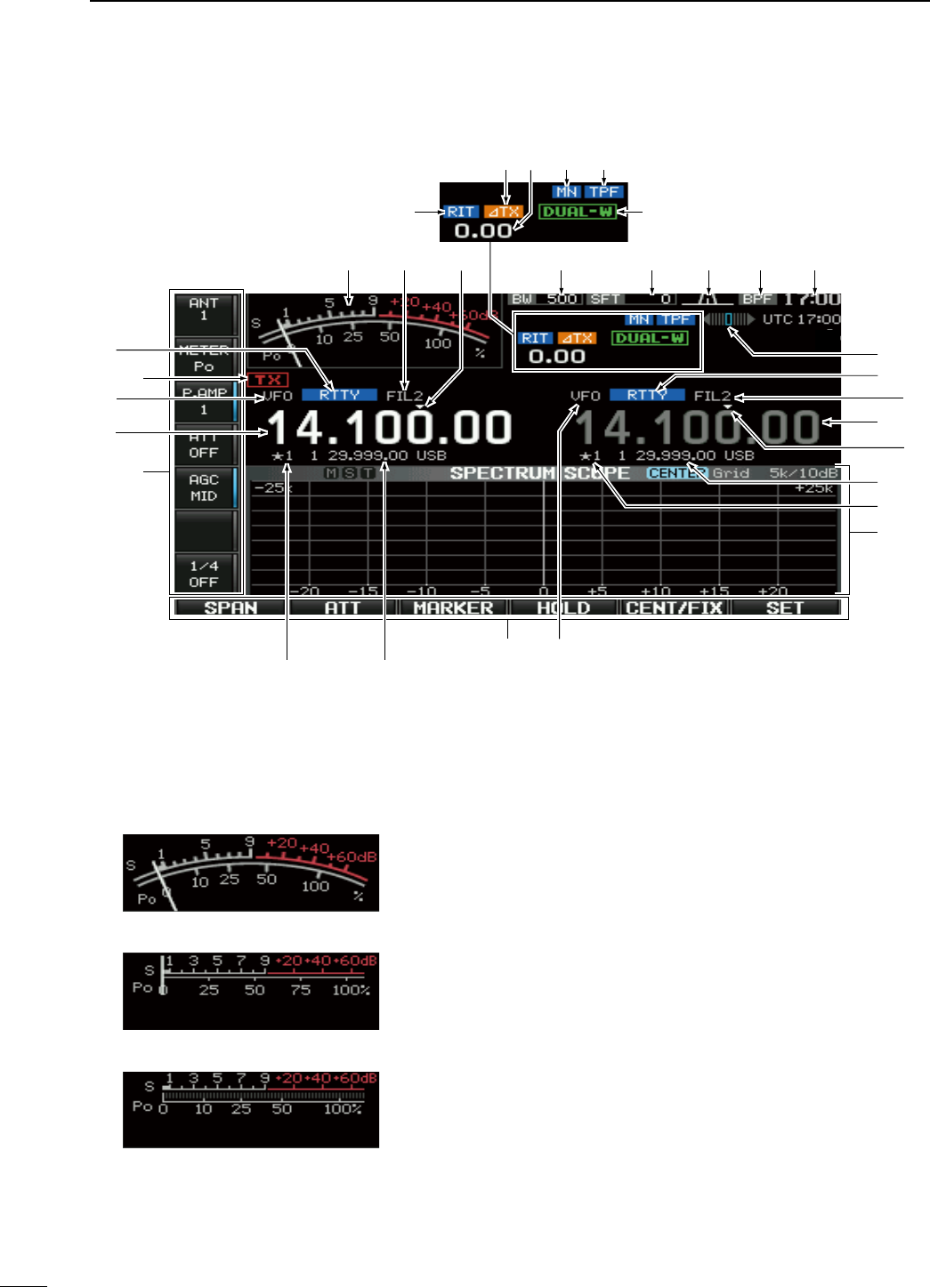
q S/RF METER (pgs. ??, ??)
Shows the signal strength while receiving. Shows
the relative output power, SWR, ALC, VD, ID or
compression levels while transmitting.
• A total of 3 meter types are available.
• Standard meter
• Edgewise meter
• Bar meter
w IF FILTER INDICATOR (p. ??)
Shows the selected IF filter number.
e QUICK TUNING INDICATOR (p. ??)
Appears when the quick tuning step function is in
use.
r BAND WIDTH INDICATOR (p. ??)
Shows the passband width of the IF filter.
t SHIFT FREQUENCY INDICATOR (p. ??)
Shows the shift frequency of the IF filter.
y PASSBAND WIDTH INDICATOR (p. ??)
Graphically displays the passband width for twin
PBT operation and center frequency for IF shift op-
eration.
u BANDPASS FILTER INDICATOR
Appears when the narrow filter (500 Hz or less) is
selected during CW, RTTY or PSK operation.
i CLOCK READOUT
Shows the current time.
Local and UTC time can be indicated at the same
time.
N LCD display
qtyuirew
o
!4
!3
!2
!1
e
w
!0
!6 !5
!2!3
!7
!5
!8
!0
!1
!9
@0 @2 @3@1
@4
13
1PANEL DESCRIPTION
o RTTY TUNING INDICATOR
Shows the tuning condition in RTTY mode.
!0 MODE INDICATOR
Shows the selected mode.
!1 FREQUENCY READOUTS
Shows the operating frequency.
• Gray characters are used for non-active readout.
!2 MEMORY CHANNEL READOUTS
± Shows the selected memory channel contents in
VFO mode.
± Shows the VFO contents in memory mode.
!3 SELECT MEMORY CHANNEL INDICATOR
(p. ??)
Indicates the displayed memory channel is set as a
select memory channel.
!4 MULTI-FUNCTION SCREEN
Shows the screens for the multi-function digital
meter, spectrum scope, voice recorder, memory list,
scan, memory keyer, RTTY decoder, PSK decoder,
IF filter selection or set modes, etc.
!5 VFO/MEMORY CHANNEL INDICATOR (p. ??)
Indicates the VFO mode or selected memory chan-
nel number.
!6 LCD FUNCTION SWITCH GUIDE
Indicates the function of the LCD function switches
([F-1] to [F-6]).
!7 MULTI-FUNCTION SWITCH GUIDE
Indicates the function of the multi-function switches.
!8 TX INDICATOR
Indicates the frequency readout for transmit.
• “ ” appears during an operating frequency is not in
an amateur band. When the band edge warning beep is
set to “OFF” (p. ??), “ ” does not appear.
• Appears on the sub band readout when the split func-
tion is turned ON.
!9 RIT INDICATOR
“ ” appears when RIT function is in use.
@0 ∂TX INDICATOR
“ ” appears when ∂TX function is in use.
@1 RIT/∂TX SHIFT FREQUENCY INDICATOR
Shows the shift frequency for the RIT or ∂TX func-
tion.
@2 NOTCH INDICATOR (p. ??)
± “ ” appears when the manual notch function
is in use. This function is available in SSB, CW,
RTTY, PSK and AM modes.
± “ ” appears when the auto notch function is in
use. This function is available in SSB, AM and
FM modes.
@3 APF/TPF INDICATOR
± “ ” appears when the audio peak filter func-
tion is in use. This function is available in CW
mode. (p. ??)
± “ ” appears when the twin peak filter func-
tion is in use. This function is available in RTTY
mode. (p. ??)
@4 DUAL WATCH INDICATOR
“ ” appears when the dualwatch function
is in use.
14
1
PANEL DESCRIPTION
1
2
3
4
5
6
7
8
9
10
11
12
13
14
15
16
17
18
19
20
21
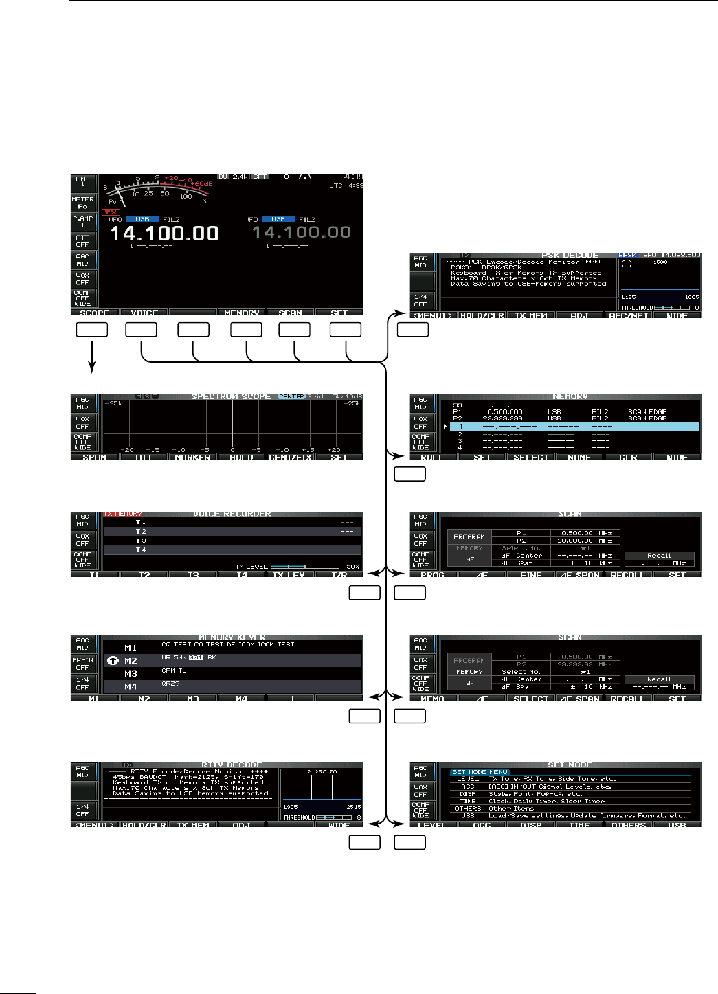
The following screens can be selected from the start
up screen. Choose the desired screen using the fol-
lowing chart.
Pushing [EXIT/SET] several times returns to the start
up screen. See p. ?? for set mode arrangement.
• Spectrum scope screen (p. ??)
• Voice recorder screen (p. ??)
• RTTY decoder screen (RTTY mode; p. ??)
• Memory keyer screen (CW mode; p. ??)
• Memory list screen (p. ??)
• PSK decoder screen (PSK mode; p. ??)
• Scan screen (VFO mode; p. ??)
• Scan screen (Memory mode; p. ??)
• Set mode menu screen (p. ??)
F-1 F-2 F-3 F-3
F-4
F-5F-2
F-5F-3
F-6F-3
F-4 F-5 F-6
N Screen menu arrangement
15
1PANEL DESCRIPTION
N Unpacking
After unpacking, immediately report any damage to the
delivering carrier or dealer. Keep the shipping cartons.
For a description and a diagram of accessory equip-
ment included with the IC-7600, see ‘Supplied acces-
sories’ on p. ?? of this manual.
N Selecting a location
Select a location for the transceiver that allows ade-
quate air circulation, free from extreme heat, cold, or
vibrations, and away from TV sets, TV antenna ele-
ments, radios and other electromagnetic sources.
The base of the transceiver has adjustable feet for
desktop use. Set the feet to one of two angles depend-
ing on your operating preference.
N Grounding
To prevent electrical shock, television interference
(TVI), broadcast interference (BCI) and other prob-
lems, ground the transceiver through the GROUND
terminal on the rear panel.
For best results, connect a heavy gauge wire or strap
to a long ground rod. Make the distance between the
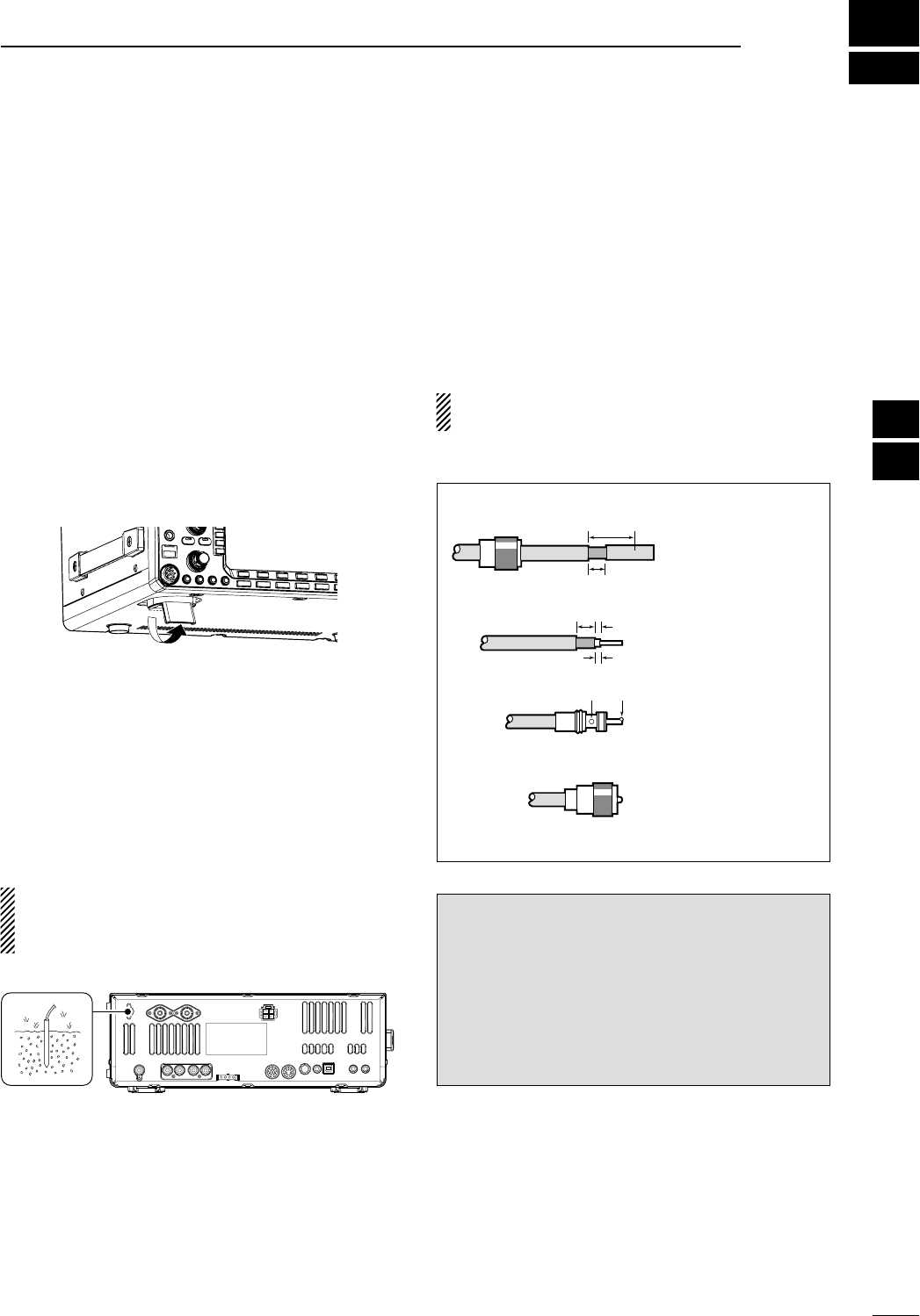
[GND] terminal and ground as short as possible.
R WARNING: NEVER connect the [GND]
terminal to a gas or electric pipe, since the connec-
tion could cause an explosion or electric shock.
[GND]
N Antenna connection
For radio communications, the antenna is of critical im-
portance, along with output power and receiver sensi-
tivity. Select antenna(s), such as a well-matched 50 ø
antenna, and feedline. We recommend 1.5:1 or better
of Voltage Standing Wave Ratio (VSWR) on your oper-
ating bands. The transmission line should be a coaxial
cable.
When using a single antenna, use the [ANT1] connec-
tor.
CAUTION: Protect your transceiver from lightning
by using a lightning arrestor.
PL-259 CONNECTOR INSTALLATION EXAMPLE
30 mm
10 mm (soft solder)
10 mm
1–2 mm
solder solder
Soft
solder
Coupling ring
Slide the coupling ring
down. Strip the cable
jacket and soft solder.
Slide the connector
body on and solder it.
Screw the coupling
ring onto the connec-
tor body.
Strip the cable as
shown at left. Soft sol-
der the center con-
ductor.
q
w
e
r
30 mm (9⁄8 in) 10 mm (3⁄8 in) 1–2 mm (1⁄16 in)
Antenna SWR
Each antenna is tuned for a specified frequency
range and SWR may be increased out-of-range.
When the SWR is higher than approx. 2.0:1, the
transceiver’s power drops to protect the final tran-
sistors. In this case, an antenna tuner is useful to
match the transceiver and antenna. Low SWR allows
full power for transmitting. The IC-7600 has an SWR
meter to monitor the antenna SWR continuously.
2
16
INSTALLATION AND CONNECTIONS
1
2
3
4
5
6
7
8
9
10
11
12
13
14
15
16
17
18
19
20
21
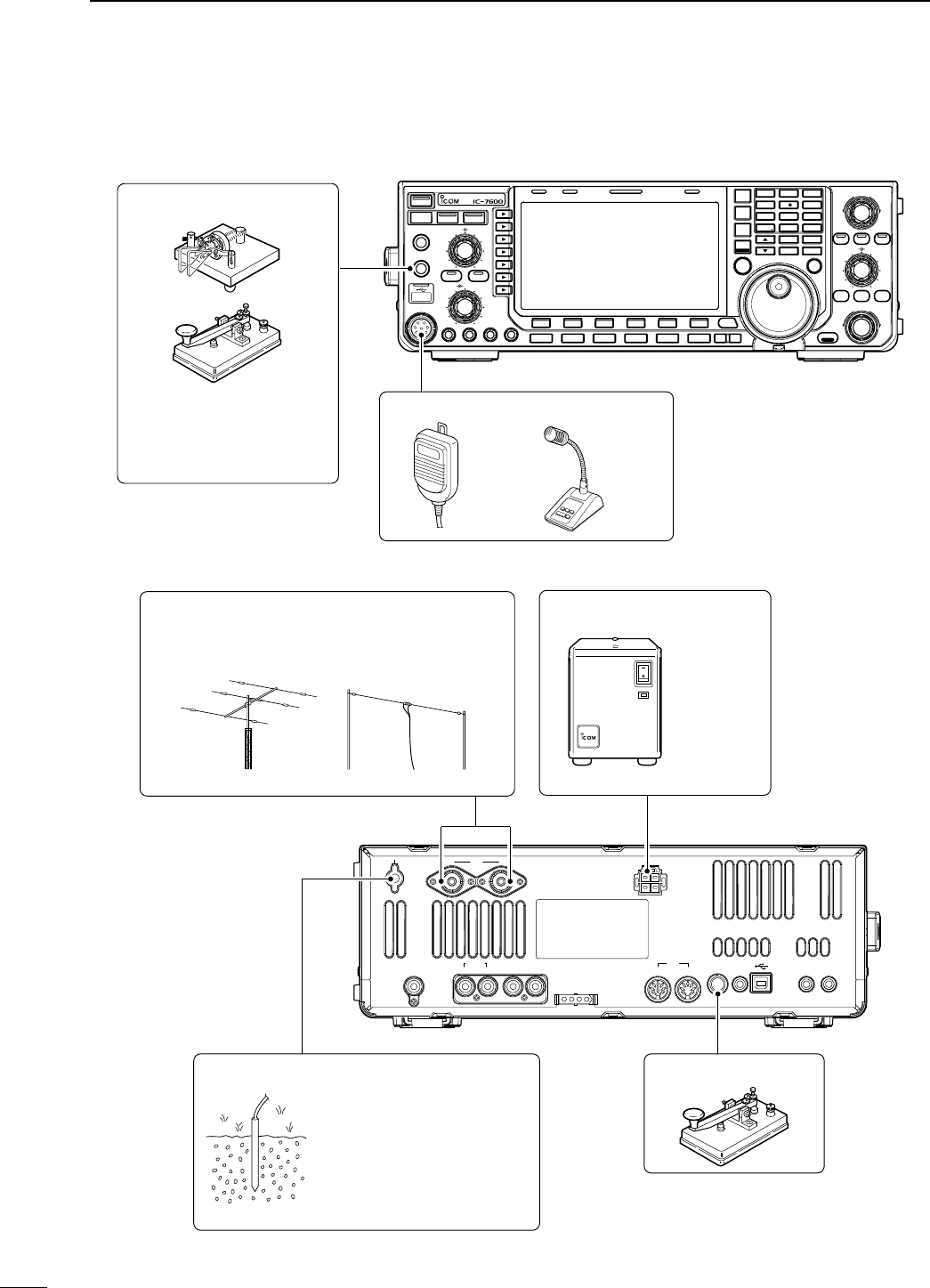
N Required connections
D Front panel
TWIN-PBT
RIT/ TX
Ӡ
NOTCH
CW PITCH
VOICE MEMORY
BAL NR
AF RF/SQL
MIC GAIN RF POWER BK-IN DELAY KEY SPEED
TIMER
PHONES
ELEC-KEY
MIC
AUTO
TUNE
GENE F-INP
1.8 3.5
12
14
5
18
6
7
3
24
8
28
9
50
0
ENT
4
7
10
21
CHANGE
TS
XFC
SPLIT
DUAL
WATCH
MAIN
/
SUB
M.SCOPE
VFO/MEMO
MP-W
MW
MP-R
F-
6
F-
5
F-
4
F-
3
F-
2
F-
1
NRNB
PBT-CLR
APF/TPF
NOTCH
POWER
RIT
CLEAR
TX
Ӡ
SPEECH
LOCK
FILTER
REC PLAY
EXIT
/
SET
SSB CW
RTTY
/
PSK
AM/ FM
MONITOR
TRANSMIT TUNER
HF/50MHz TRANSCEIVER
LOCKTX RX SPLIT
CW KEY
A straight key can be used
when the internal electronic
keyer is turned OFF in
keyer set mode. (p. ??)
MICROPHONES (p. ??)
SM-50HM-36
D Rear panel
12ANT DC 13.8V
X-VERTER
RX-ANT
ACC
TUNER
IN OUT ALC SEND KEY
12
METER
REMOTE EXT
-
SP
ANTENNA 1, 2 (p. ??)
STRAIGHT KEY
GROUND
(p. ??)
Use the heaviest gauge
wire or strap available and
make the connection as
short as possible.
Grounding prevents electri-
cal shocks, TVI and other
problems.
DC POWER SUPPLY (p. ??)
PS-126
ANT1 for 1.8–18 MHz bands
ANT 2 for 21–28 MHz bands
[Example]:
17
2INSTALLATION AND CONNECTIONS
18
2
INSTALLATION AND CONNECTIONS
1
2
3
4
5
6
7
8
9
10
11
12
13
14
15
16
17
18
19
20
21
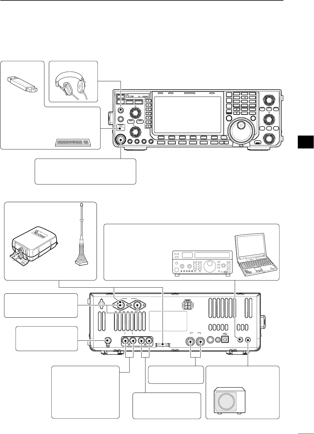
N Advanced connections
D Front panel
TWIN-PBT
RIT/ TX
Ӡ
NOTCH
CW PITCH
VOICE MEMORY
BAL NR
AF RF/SQL
MIC GAIN RF POWER BK-IN DELAY KEY SPEED
TIMER
PHONES
ELEC-KEY
MIC
AUTO
TUNE
GENE F-INP
1.8 3.5
12
14
5
18
6
7
3
24
8
28
9
50
0
ENT
4
7
10
21
CHANGE
TS
XFC
SPLIT
DUAL
WATCH
MAIN
/
SUB
M.SCOPE
VFO/MEMO
MP-W
MW
MP-R
F-
6
F-
5
F-
4
F-
3
F-
2
F-
1
NRNB
PBT-CLR
APF/TPF
NOTCH
POWER
RIT
CLEAR
TX
Ӡ
SPEECH
LOCK
FILTER
REC PLAY
EXIT
/
SET
SSB CW
RTTY
/
PSK
AM/ FM
MONITOR
TRANSMIT TUNER
HF/50MHz TRANSCEIVER
LOCKTX RX SPLIT
MIC
USB-MEMORY
The AFSK modulation signal can also
be input to [MIC].
HEADPHONES
KEYBOARD
Connects an USB type PC keyboard
directly for RTTY/PSK operation, as
well as other text edit operations.
D Rear panel— 1
12ANT DC 13.8V
X-VERTER
RX-ANT
ACC
TUNER
IN OUT ALC SEND KEY
12
METER
REMOTE EXT
-
SP
RX ANT IN/OUT
Connects an external
preamp or lowpass filter.
RX ANT IN/OUT must be
activated in the antenna
set screen (p. ??).
ACC SOCKETS 1, 2
(pgs. ??, ??)
ANTENNA 1, 2 (p. ??)
Connects a linear amplifier,
antenna selector, etc.
[X-VERTER]
Connects a transverter
for V/UHF band use.
[ALC], [SEND] (p. ??)
Used for connecting a
non-Icom linear amplifier.
EXTERNAL SPEAKER
(p. ??)
SP-23
(option)
[REMOTE] (p. ??)
Used for computer
control and transceive
operation.
The optional CT-17 is
required when connect-
ing a PC to [REMOTE].
AH-4 (p. ??) AH-2b
or long wire
with
D Rear panel— 2
12ANT DC 13.8V
X-VERTER
RX-ANT
ACC
TUNER
IN OUT ALC SEND KEY
12
METER
REMOTE EXT
-
SP
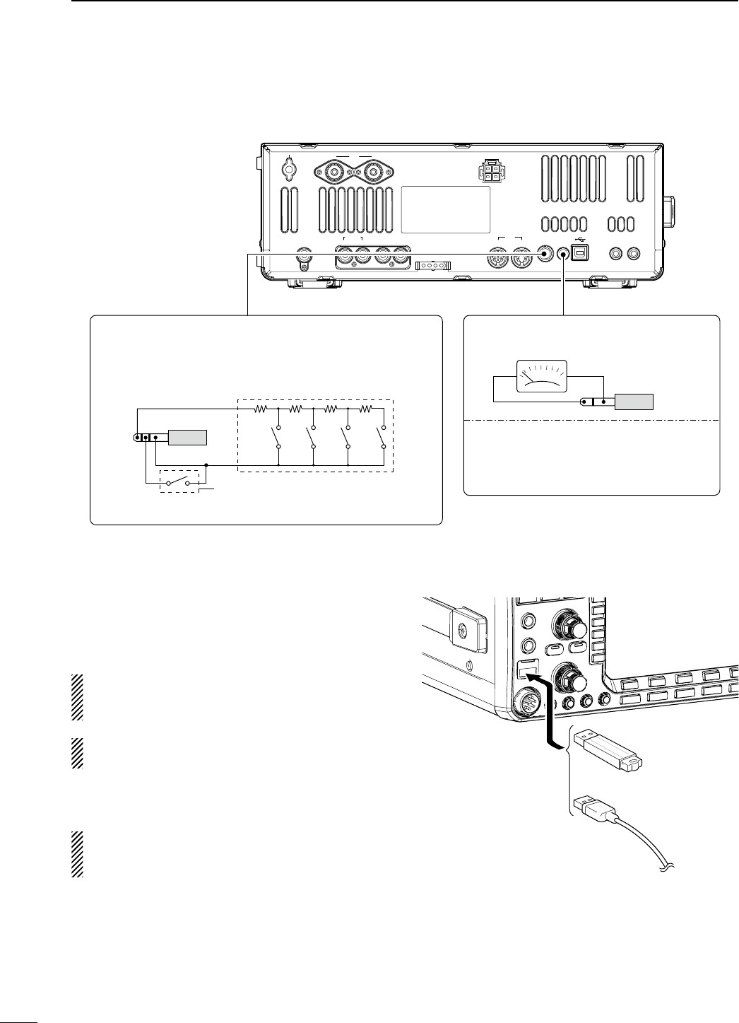
EXTERNAL KEYPAD
Connects an external keypad for direct voice memory,
keyer memory, RTTY TX memory and PSK TX memory
controls.
1.5 kø
±5%
1.5 kø
±5%
2.2 kø
±5%
4.7 kø
±5%
S1
(T1/M1)
S2
(T2/M2)
S3
(T3/M3)
S4
(T4/M4)
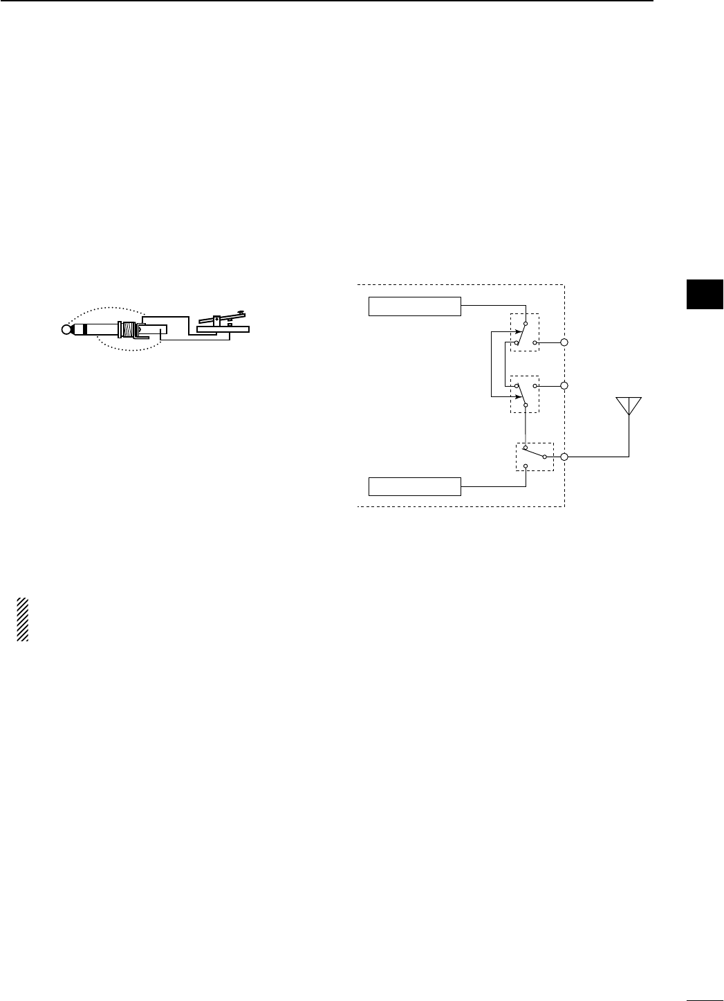
EXTERNAL KEYPAD
6.35 (d) mm; 1⁄4" plug
Mute switch: Mutes both transmis-
sion and reception when switched
ON during transceive operation, etc.
[METER]
Connects an external meter, etc.
3.5 (d) mm; 1⁄8" plug
Output impedance : 4.7 kø
Output voltage (open circuit) : 2.5 V (default)
Output voltage can be adjusted 0 to 5 V
in ACC set mode. (p. ??)
N USB connection
Connect the USB-Memory* to the USB connector (A
type) on the front panel.
• Unmount operation is recommended before removing the
USB-Memory* (p.??).
Make sure to connect the USB-Memory correctly.
NEVER connect or remove the USB-Memory when
the read/write indicator lights or blinks.
An USB keyboard* or an USB hub* can also be con-
nected to the USB connector.
* USB-Memory, USB keyboard or USB hub is not supplied
by Icom.
When the transceiver is connected to PC, an USB
cable (third party) should be connected to the USB
connector (B type) on the rear panel. (p. ??)
or
19
2INSTALLATION AND CONNECTIONS
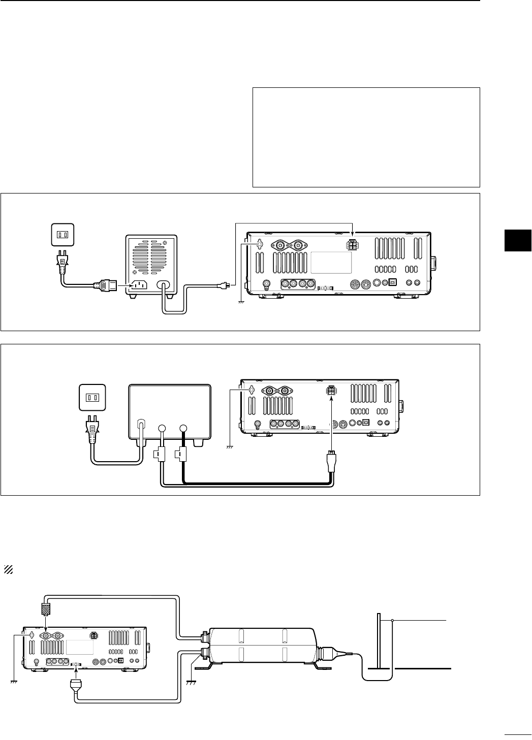
N Power supply connections
Use a DC power supply with a 23 A capacity when
operating the transceiver with AC power. Refer to the
diagrams below.
CAUTION: Before connecting the DC power cable,
check the following important items. Make sure:
• The [POWER] switch is OFF.
• Output voltage of the power source is 12–15 V
when you use a non-Icom power supply.
• DC power cable polarity is correct.
Red : Positive + terminal
Black : Negative
_ terminal
CONNECTING A DC POWER SUPPLY
A DC power supplyAC outlet
AC cable
30 A fuses
Supplied DC power cable
13.8 V; at least 23 A
_+
Transceiver
To DC power
socket
GND
BlackRed
N External antenna tuner connection
CONNECTING THE AH-4
The AH-4 must be connected to [ANT1].
Coaxial cable (from the AH-4)
[ANT1]
Control cable
Transceiver
GND
AH-4
Long wire or optional AH-2b
[TUNER]
GND
CONNECTING PS-126 DC POWER SUPPLY
PS-126
DC power
cable
To DC power socket Transceiver
AC outlet
AC cable
GND
20
2
INSTALLATION AND CONNECTIONS
1
2
3
4
5
6
7
8
9
10
11
12
13
14
15
16
17
18
19
20
21
N Linear amplifier connections
D Connecting the IC-PW1/EURO
EXCITER
11&2
To an
antenna ACC-1
ANT
ANT2ANT1 ACC 2
INPUT1
INPUT2
REMOTE
GND
IC-PW1/EURO
AC outlet
(Non-European versions : 100–120/220–240 V
European version : 230 V)
Transceiver
REMOTE
Remote control cable (supplied with the IC-PW1/EURO)
ACC cable (supplied with the IC-PW1/EURO)
Be sure to connect the cable
to the 7-pin ACC 2 jack.
Coaxial cable
(supplied with the
IC-PW1/EURO)
Coaxial cable*
*Purchase separately
Connect
[INPUT2]
if necessary
GND
GND
D Connecting a non-Icom linear amplifier
RF OUTPUT RF INPUT
ALC
SEND
50 ø
coaxial
cable
Transceiver
ANT1
ALC SEND
To an
antenna
Non-Icom linear amplifier
R WARNING:
Set the transceiver output power and linear am-
plifier ALC output level after referring to the linear
amplifier instruction manual.
The ALC input level must be in the range 0 V to
–4 V. The transceiver does not accept positive volt-
age. Non-matched ALC and RF power settings
could overheat or damage the linear amplifier.
The maximum signal level of [SEND] jack is
16 V/0.5 A DC with initial setting, and 250 V/
200 mA with “MOSFET” setting (see p. ?? for de-
tails). Use an external relay unit if your non-Icom
linear amplifier requires control voltage and/or cur-
rent greater than specified.
21
2INSTALLATION AND CONNECTIONS
N Transverter jack information
When 2 to 13.8 V is applied to pin 6 of [ACC 2], the
[X-VERTER] connector is activated for transverter op-
eration and the antenna connectors do not receive or
transmit any signals.
While receiving, the [X-VERTER] connector can be acti-
vated as an input terminal from an external transverter.
While transmitting, the [X-VERTER] connector outputs
signals of the displayed frequency at –20 dBm (22 mV)
as signals for the external transverter.
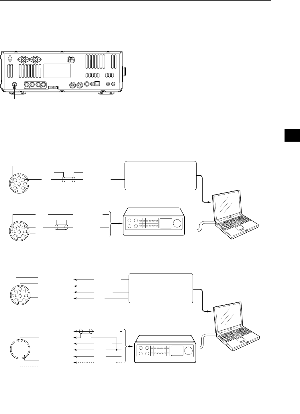
N FSK and AFSK (SSTV) connections
To connect a TNC or scan converter, etc., refer to the diagram below.
D FSK operation— when connecting to [ACC 1]
D AFSK operation
D When connecting to the [USB] connector
Connect an USB cable (third party’s) between the transceiver’s USB connector [USB] (B) on the rear panel and
PC. (p. ??)
• Icom HP (http://www.icom.co.jp/world/support/index.html) gives the USB driver and the installation guide download service.
Transverter connector
PC
RS-232C
TNC or scan converter
• When using a PC application
• When using a TNC
1
2
3
45
67
8
Rear panel view
Rear panel view
RTTY
GND
AF
SEND
RTTY
GND
AF
SEND
RTTY OUTPUT
GND
AUDIO INPUT
PTT
RTTY OUTPUT
GND
AUDIO INPUT
PTT
1
2
3
45
67
8
Connect to serial port, parallel
port, speaker jack, microphone
jack and line IN/OUT jack, etc.
See the instruction manual of the
application for details.
Connect to serial port, parallel
port, speaker jack, microphone
jack and line IN/OUT jack, etc.
See the instruction manual of
the application for details.
• When connecting to [ACC 1]
• When connecting to [MIC]
• When using a PC application
• When using a TNC
PC
RS-232C
TNC or scan converter
PTT
Audio output
AF input
GND
AFSK output
AF input
GND
PTT*
SQL input†
*When using the VOX function, no need to connect. Refer to the instruction
manual of the external equipment (TNC, etc.).
†When connecting the squelch line, consult the necessary manual (TNC, etc.).
q
w
ert
y
u
i
1
2
3
45
67
8
z
z
x
x
c
c
v
v*
z
x
c
v
z
x
c
v
b
b
n†
n†
b
n†
Rear panel view
Rear panel view
22
2
INSTALLATION AND CONNECTIONS
1
2
3
4
5
6
7
8
9
10
11
12
13
14
15
16
17
18
19
20
21
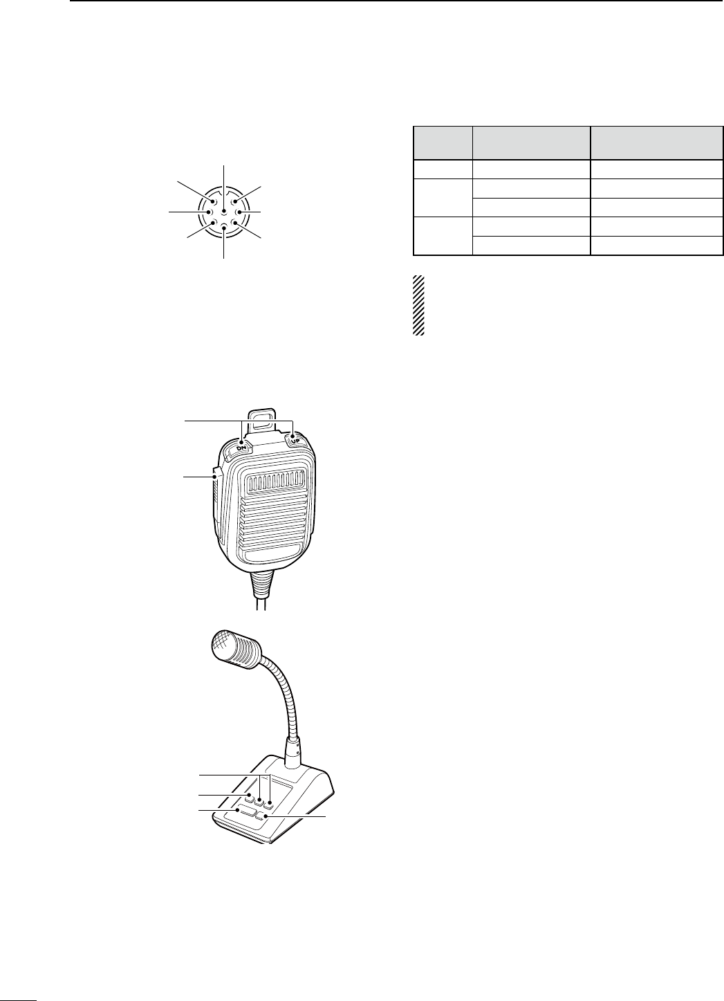
N Microphone connector information
(Front panel view)
y GND (PTT ground)
t PTT
r Main readout squelch switch
q Microphone input
w +8 V DC output
e Frequency up/down
i Main readout AF output
(varies with [AF])
GND
(Microphone ground
)
u
[MIC]
Pin No. FUNCTION DESCRIPTION
w+8 V DC output Max. 10 mA
eFrequency up Ground
Frequency down Ground through 470 ˘
rSquelch open “Low” level
Squelch closed “High” level
CAUTION: DO NOT short pin 2 to ground as this
can damage the internal 8 V regulator. DC voltage is
applied to pin 1 for microphone operation. Use cau-
tion when using a non-Icom microphone.
N Microphones
D HM-36
D SM-50
(option)
q
w
q
w
r
e
q UP/DOWN SWITCHES [UP]/[DN]
Change the selected readout frequency or memory
channel.
• Pressing a switch continuously changes the frequency
or memory channel number continuously.
• While pushing [XFC], the transmit readout frequency
can be controlled while in split frequency operation.
• The [UP]/[DN] switch can simulate a key paddle. Preset
in the keyer set mode. (p. ??)
w PTT SWITCH
Push and hold to transmit; release to receive.
e PTT LOCK SWITCH (available for SM-50 only)
Push to toggle between transmit and receive.
r LOW CUT SWITCH (available for SM-50 only)
Push to cut out the low frequency components of
input voice signals.
23
2INSTALLATION AND CONNECTIONS
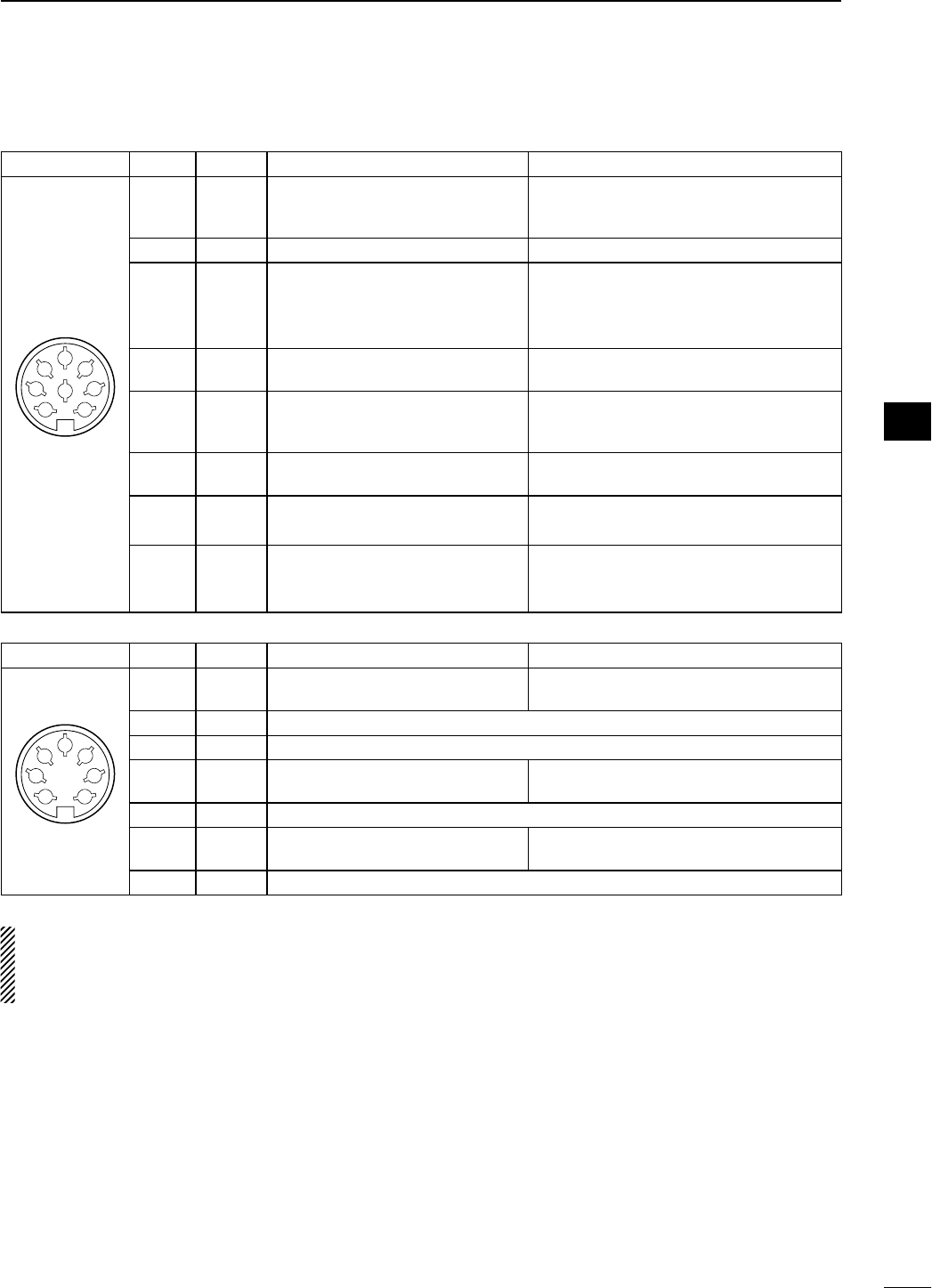
N Accessory connector information
ACC 1
PIN No.
NAME DESCRIPTION SPECIFICATIONS
1
2
3
45
67
8
1 RTTY Controls RTTY keying
“High” level
“Low” level
Output current
: More than 2.4 V
: Less than 0.6 V
: Less than 2 mA
2 GND Connects to ground. Connected in parallel with ACC 2 pin 2.
3
SEND
Input/output pin.
Goes to ground when transmitting.
When grounded, transmits.
Ground level
Output current
Input current (Tx)
: –0.5 V to 0.8 V
: Less than 20 mA
: Less than 200 mA
Connected in parallel with ACC 2 pin 3.
4 MOD Modulator input.
Connects to a modulator
Input impedance
Input level
: 10 k˘
: Approx. 100 mV rms
5AF
AF detector output.
Fixed, regardless of [AF] position in
default settings. (see notes below)
Output impedance
Output level
: 4.7 k˘
: 100–300 mV rms
6 SQLS Squelch output.
Goes to ground when squelch opens.
SQL open
SQL closed
: Less than 0.3 V/5 mA
: More than 6.0 V/100 μA
7 13.8 V 13.8 V output when power is ON. Output current : Max. 1 A
Connected in parallel with ACC 2 pin 7.
8 ALC ALC voltage input.
Control voltage
Input impedance
: –4 V to 0 V
: More than 10 k˘
Connected in parallel with ACC 2 pin 5.
ACC 2
PIN No.
NAME DESCRIPTION SPECIFICATIONS
1
2
3
45
67
1 8 V Regulated 8 V output. Output voltage
Output current
: 8.0 V ±0.3 V
: Less than 10 mA
2 GND Same as ACC 1 pin 2.
3
SEND
Same as ACC 1 pin 3.
4 BAND Band voltage output.
(Varies with amateur band) Output voltage : 0 to 8.0 V
5 ALC Same as ACC 1 pin 8.
6TRV
Activates [X-VERTER] input/output
when “HIGH” voltage is applied.
Input impedance
Input voltage
: More than 10 k˘
: 2 to 13.8 V
7 13.8 V Same as ACC 1 pin 7.
NOTE: If the CW side tone level limit or beep level
limit is in use, the CW side tone or beep tone de-
creases from the fixed level when the [AF] control is
rotated above a specified level. (p. ??)
24
2
INSTALLATION AND CONNECTIONS
1
2
3
4
5
6
7
8
9
10
11
12
13
14
15
16
17
18
19
20
21
N Before first applying power
Before first applying power, make sure all connec-
tions required for your system are complete by refer-
ring to Chapter 2.
After all connections have been done, set controls
and switches as shown in the figure below.
TWIN-PBT
RIT/ TX
Ӡ
NOTCH
CW PITCH
VOICE MEMORY
BAL NR
AF RF/SQL
MIC GAIN RF POWER BK-IN DELAY KEY SPEED
TIMER
PHONES
ELEC-KEY
MIC
AUTO
TUNE
GENE F-INP
1.8 3 . 5
12
14
5
18
6
7
3
24
8
28
9
50
0
ENT
4
7
10
21
CHANGE
TS
XFC
SPLIT
DUAL
WATCH
MAIN
/
SUB
M.SCOPE
VFO/MEMO
MP-W
MW
MP-R
F-
6
F-
5
F-
4
F-
3
F-
2
F-
1
NRNB
PBT-CLR
APF/TPF
NOTCH
POWER
RIT
CLEAR
TX
Ӡ
SPEECH
LOCK
FILTER
REC PLAY
EXIT
/
SET
SSB CW
RTTY
/
PSK
AM/FM
MONITOR
TRANSMIT TUNER
HF/50MHz TRANSCEIVER
LOCKTX RX SPLIT
[NOTCH]
: 12 o’clock
[NR]
: Max. CCW
[RF POWER]
: Max. CW
[BK-IN DELAY]
: 12 o’clock
[KEY SPEED]
: 10–12 o’clock
[MIC GAIN]
: 12 o’clock
[BAL]
: 12 o’clock
[AF]
: Max. CCW
[RF/SQL]
: 12 o’clock
[CW PITCH]
: 12 o’clock
: Max. clockwise
: Max. counterclockwise
CW
CCW
N Applying power (CPU resetting)
First applying power:
Reset the transceiver using the following procedure.
Resetting CLEARS all programmed contents in
memory channels and returns programmed values
in set mode to default values.
q Make sure the transceiver power is OFF.
w While pushing and holding [F-INP ENT] and [MW],
push [POWER] to turn power ON.
• The CPU is reset.
• The CPU start-up takes approx. 5 sec.
• The transceiver displays its initial VFO frequencies
when resetting is complete.
e Change the set mode settings after resetting, if
desired.
Normal applying power:
Push [POWER] to turn power ON, then check the dis-
play. When any of indicators appear, turn them OFF if
necessary. (See the appropriate page for details.)
POWER F-INP ENT
MW
In cooler temperatures, the LCD may appear dark
and unstable after turning power ON. This is nor-
mal and does not indicate any equipment malfunc-
tion.
3
25
BASIC OPERATION
N Selecting VFO/memory mode
± Push [VFO/MEMO] to switch between VFO and
memory modes.
• “VFO” appears when in VFO mode, or the selected
memory channel number appears when in memory
mode.
• Pushing and holding [VFO/MEMO] for 1 sec. transfers
the contents of the selected memory channel to VFO
mode. (p. ??)
N Main/Sub band selection
The IC-7600 has 2 identical receivers, main and sub.
The main band is displayed on the left hand side, and
the sub band is displayed on the right hand side of
the LCD. Some functions can only be applied to the
selected band and transmission occurs on the main
band (except during split frequency operation).
± Push [MAIN/SUB M.SCOPE] to select access to
the main or sub readout.
• The selected readout frequency is displayed clearly.
The sub readout functions only during split operation or
dualwatch.
D Main/Sub band switching
± Push [CHANGE] to switch the frequency and
selected memory channel between main and sub
readouts.
• Switches between transmit frequency and receive fre-
quency when the split frequency function is ON. (p. ??)
D Main/Sub band equalization
± Push and hold [CHANGE] for 1 sec. to equalizes
the sub readout frequency to the main readout fre-
quency.
VFO/MEMO
MAIN
/SUB
M.SCOPE
M.SCOPE
CHANGE
“VFO” indicator Memory channel number
Access to SUB VFO
MAIN VFO SUB VFO
Access to MAIN VFO
MAIN VFO SUB VFO
26
3
BASIC OPERATION
1
2
3
4
5
6
7
8
9
10
11
12
13
14
15
16
17
18
19
20
21
N Selecting an operating band
The triple band stacking register provides 3 memories
for each band key, storing frequency and mode infor-
mation.
This function is convenient when you operate 3 oper-
ating modes on one band. For example, one register
is used for a CW frequency, another for a SSB fre-
quency and the other one for a RTTY frequency.
If a band key is pushed once, the frequency and oper-
ating mode last used are called up. When the key is
pushed again, another stored frequency and operat-
ing mode are called up.
See the table below for a list of the bands available
and the default settings for each band.
Band keys
BAND REGISTER 1 REGISTER 2 REGISTER 3
1.8 MHz 1.900000 MHz CW 1.910000 MHz CW 1.915000 MHz CW
3.5 MHz 3.550000 MHz LSB 3.560000 MHz LSB 3.580000 MHz LSB
7 MHz 7.050000 MHz LSB 7.060000 MHz LSB 7.020000 MHz CW
10 MHz 10.120000 MHz CW 10.130000 MHz CW 10.140000 MHz CW
14 MHz 14.100000 MHz USB 14.200000 MHz USB 14.050000 MHz CW
18 MHz 18.100000 MHz USB 18.130000 MHz USB 18.150000 MHz USB
21 MHz 21.200000 MHz USB 21.300000 MHz USB 21.050000 MHz CW
24 MHz 24.950000 MHz USB 24.980000 MHz USB 24.900000 MHz CW
28 MHz 28.500000 MHz USB 29.500000 MHz USB 28.100000 MHz CW
50 MHz 50.100000 MHz USB 50.200000 MHz USB 51.000000 MHz FM
General 15.000000 MHz USB 15.100000 MHz USB 15.200000 MHz USB
D Using the band stacking registers
[Example]: 14 MHz band
q Push [14 5], then select a frequency and an oper-
ating mode.
• A frequency and an operating mode are memorized in
the first band stacking register.
w Push [14 5] again, then select another frequency
and operating mode.
• This frequency and operating mode are memorized in
the second band stacking register.
e Push [14 5] again, then select another frequency
and operating mode.
• This frequency and operating mode are memorized in
the third band stacking register.
• When a fourth frequency and operating mode are
selected on a band, the first register set in step q, is
over written.
GENE F-INP
1.8 3.5
12
14
5
18
6
7
3
24
8
28
9
50
0
ENT
4
7
10
21
27
3BASIC OPERATION
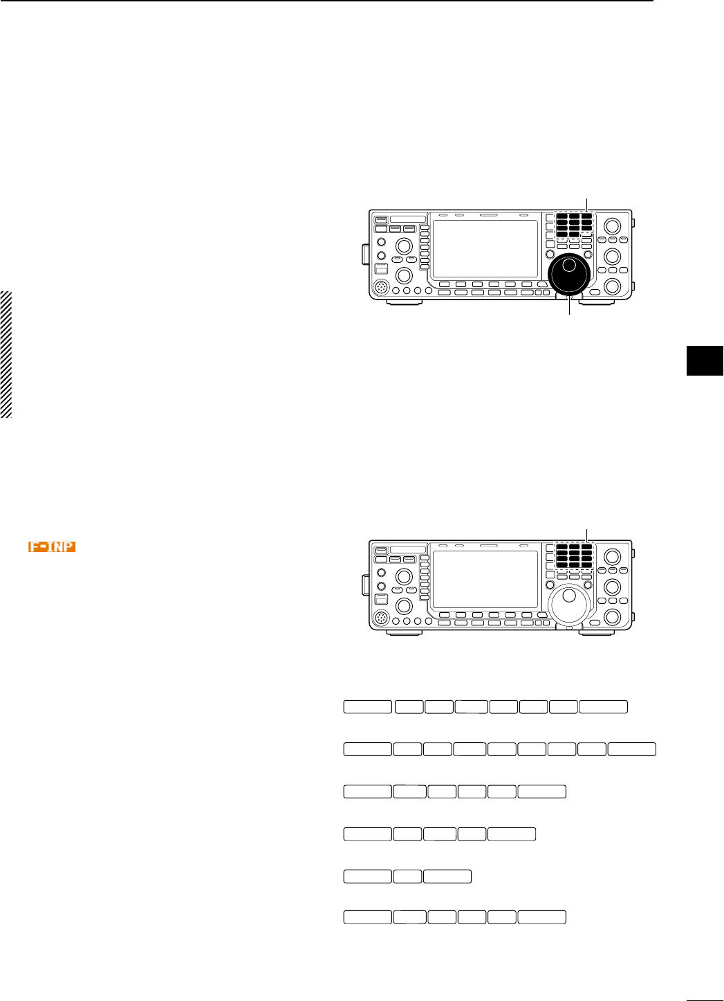
N Frequency setting
The transceiver has several tuning methods for con-
venient frequency tuning.
D Tuning with the main dial
q Push the desired band key on the keypad 1–3
times.
• 3 different frequencies can be selected on each band
with the band key. (See previous page “Using the band
stacking registers.”)
w Rotate the main dial to set the desired frequency.
If the dial lock function is activated, the lock indica-
tor lights, and the main dial does not function.
In this case, push and hold [SPEECH/LOCK] for
1 sec. to deactivate the lock function.
When “LOCK/SPEECH” is selected in “[SPEECH/
LOCK] Switch” item in others set mode, pushing
[SPEECH/LOCK] deactivates the lock function.
(see p. ?? for details)
D Direct frequency entry with the keypad
The transceiver has a keypad for direct frequency
entry as described below.
q Push [F-INP ENT].
• “ ” indicator appears.
w Input the desired frequency.
• Push [GENE •] to input “. (decimal point)” between the
MHz units and kHz units.
e Push [F-INP ENT] to set the input frequency.
•
To cancel the input, push any other key instead of
[F-INP ENT] or keypad
.
Main dial
Band keys
Keypad
1.8 13.5 2
F-INP ENT F-INP ENT
10 4
GEN
•
50 014 5
1.8 121 7
F-INP ENT F-INP ENT
24 8
GEN
•
50 03.5 214 5
50 0
F-INP ENT F-INP ENT
GEN
•
21 718 6
10 4
F-INP ENT F-INP ENT
GEN
•
3.5 214 5
1.8 1
F-INP ENT F-INP ENT
GEN
•
14 5
F-INP ENT F-INP ENT
21 7
[EXAMPLE]
14.025 MHz
18.0725 MHz
706 kHz
5.100 MHz
7.000 MHz
21.280 MHz 21.245 MHz
28
3
BASIC OPERATION
1
2
3
4
5
6
7
8
9
10
11
12
13
14
15
16
17
18
19
20
21
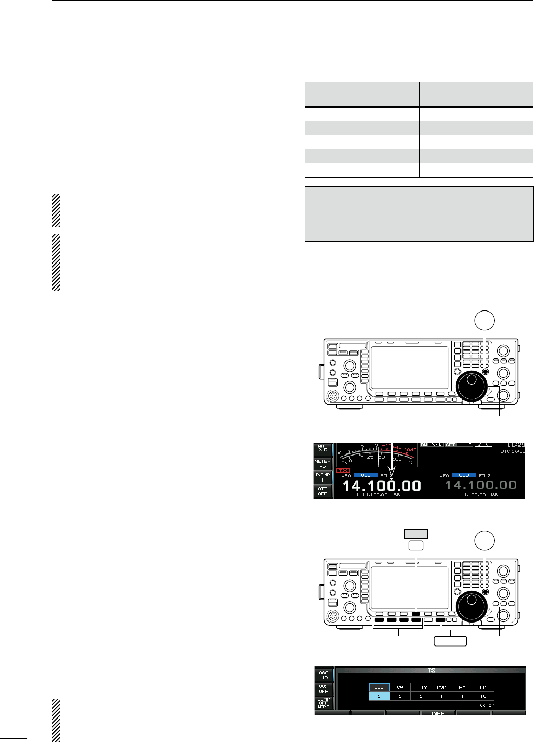
D About 5 MHz band operation (USA version only)
Operation on the 5 MHz band is allowed on 5 discrete
frequencies and must adhere to the following:
• USB mode
• Maximum of 50 watts ERP (Effective Radiated Power)
• 2.8 kHz bandwidth
It’s your responsibility to set all controls so that trans-
mission in this band meets the stringent conditions
under which amateur operations may use these fre-
quencies.
NOTE: We recommend that you store these fre-
quencies, mode and filter settings into memory
channels for easy recall.
* The FCC specifies center frequencies on the
5 MHz band. However, the IC-7600 displays car-
rier frequency. Therefore, tune the transceiver to
1.5 kHz below the specified FCC channel center
frequency.
D Quick tuning step
The operating frequency can be changed in larger
steps (0.1, 1, 5, 9, 10, 12.5, 20 or 25 kHz selectable)
for quick tuning.
q Push [TS] to turn the quick tuning function ON.
• “Z” appears when the quick tuning function is ON.
w Rotate the main dial to change the frequency in
programmed kHz steps.
e Push [TS] again to turn the quick tuning function
OFF.
• “Z” disappears.
r Rotate the main dial for normal tuning if desired.
D Selecting “kHz” step
q Push [TS] to turn the quick tuning function ON.
• “Z” appears when the quick tuning function ON.
w Push and hold [TS] for 1 sec. to enter quick tuning
step set mode.
• Selected tuning steps for all modes appear.
e Select the desired operating mode.
r Rotate the main dial to select the desired tuning
step.
• Push and hold [DEF] (F-4) for 1 sec. to return to the
default setting, if desired.
t Repeat steps e and r to select quick tuning steps
for other modes, if desired.
y Push [EXIT/SET] to exit the setting display.
NOTE: When entering quick tuning step set mode,
the quick tuning function must be activated first.
The main and sub bands have independent tuning
step settings.
IC-7600 Displayed
Frequency*
FCC Channel
Center Frequency*
5.33050 MHz 5.33200 MHz
5.34650 MHz 5.34800 MHz
5.36650 MHz 5.36800 MHz
5.37150 MHz 5.37300 MHz
5.40350 MHz 5.40500 MHz
To assist you in operating the 5 MHz band within
the rules specified by the FCC, transmission is
illegal on any 5 MHz band frequency other than the
five frequencies indicated in the table above.
Main dial
TS
Main dial
TS
Mode selection
F-4
EXIT/SET
DEF
Quick tuning indicator
29
3BASIC OPERATION
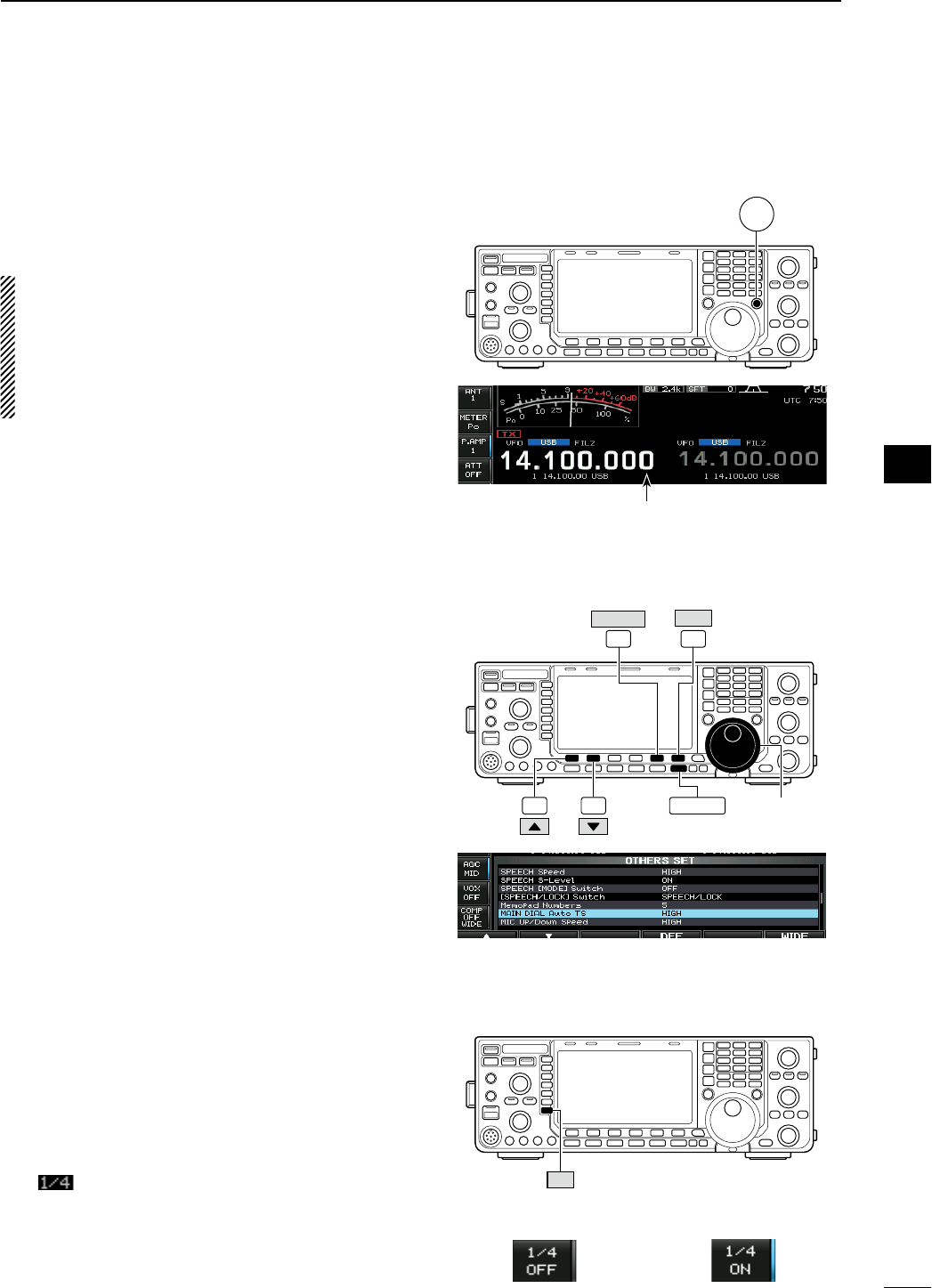
D Selecting 1 Hz step
A minimum tuning step of 1 Hz can be used for fine
tuning.
q Push [TS] to turn the quick tuning function OFF.
w Push and hold [TS] for 1 sec. to turn the 1 Hz tun-
ing step ON and OFF.
NOTE:
• RIT and/or ∂TX also functions in 1 Hz tuning step
when used.
• The frequency is changed in 50 Hz step when the
[UP]/[DN] switches of the microphone are used
for the frequency setting (when the programma-
ble tuning step is not selected.)
D Auto tuning step function
When rotating the main dial rapidly, the tuning speed
accelerates automatically as selected.
q Push [EXIT/SET] several times to close a multi-
function screen, if necessary.
w Push [SET] (F-6) to select set mode menu screen.
• Pushing and holding [EXIT/SET] for 1 sec. also selects
set mode menu screen.
e Push [OTHERS] (F-5) to enter others set mode.
r Push [Y] (F-1) or [Z] (F-2) to select “MAIN DIAL
Auto TS.”
t Rotate the main dial to select the desired condition
from HIGH, LOW and OFF.
• HIGH : Approx. 5 times faster when the tun-
ing step is set to 1 kHz or smaller steps;
approx. 2 times faster when the tuning
step is set to 5 kHz or larger steps.
• LOW : Approx. 2 times faster
• OFF : Auto tuning step is turned OFF.
y Push [EXIT/SET] to exit the set mode.
D 1⁄4 tuning step function
When operating in SSB data, CW, RTTY or PSK, the
1⁄4 tuning function is available. Dial rotation is reduced
to 1⁄4 of normal speed when the 1⁄4 tuning function is
ON for finer tuning control.
± Push [1/4] (MF7) to toggle the 1⁄4 tuning function
ON and OFF.
• “ ” appears when the 1⁄4 tuning function is ON.
TS
Main dial
F-1 F-2
F-6
EXIT/SET
SET
F-5
OTHERS
1 ⁄ 4
¼ tuning step OFF ¼ tuning step ON
1 Hz step indicator
HIGH (default)
30
3
BASIC OPERATION
1
2
3
4
5
6
7
8
9
10
11
12
13
14
15
16
17
18
19
20
21
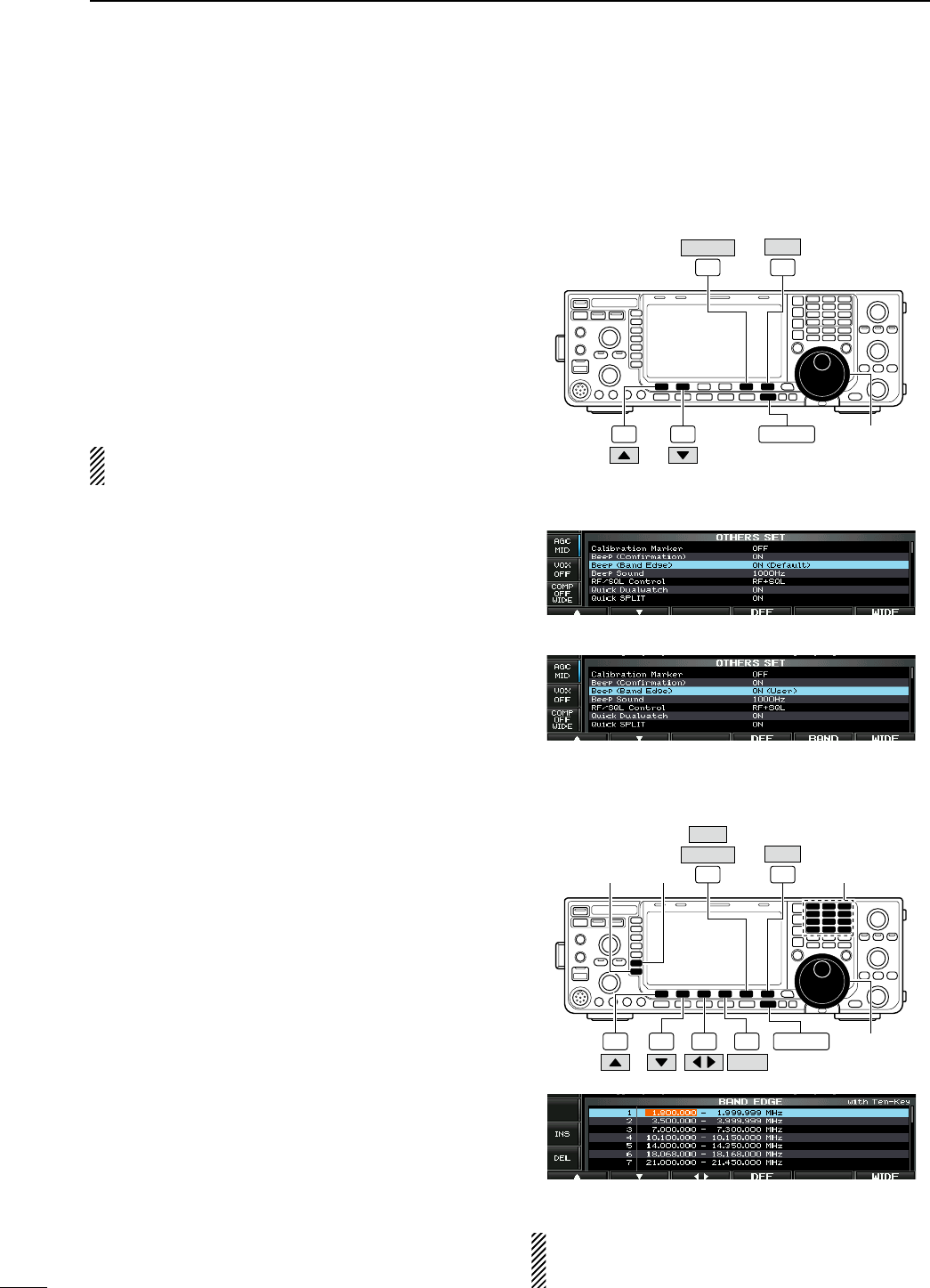
D Band edge warning beep
When you tune outside of an amateur band’s fre-
quency range, a warning beep sounds.
This function can be turned OFF in set mode, if desired.
q Push [EXIT/SET] several times to close a multi-
function screen, if necessary.
w Push [SET] (F-6) to select set mode menu screen.
• Pushing and holding [EXIT/SET] for 1 sec. also selects
set mode menu screen.
e Push [OTHERS] (F-5) to enter others set mode.
r Push [Y] (F-1) or [Z] (F-2) to select “Beep (Band
Edge).”
t Rotate the main dial to select the band edge warn-
ing beep function.
y Push [EXIT/SET] to exit the set mode.
The beep output level can be set in level set mode.
(p. ??)
When the band edge warning beep is set to “ON”:
The band edge warning beep is activated according
to the set mode setting as follows.
• ON (Default)
Band edge beep sounds when an operating frequency
enters or exits a default amateur band. (default)
• ON (User)
A beep sounds when an operating frequency enters or
exits an amateur band that is set in band edge screen.
• ON (User) & TX Limit
A beep sounds when an operating frequency enters
or exits an amateur band that is set in band edge
screen and transmission is limited out of the band.
To programming the band edge:
When “ON (User)” or “ON (User) & TX Limit” is
selected, [BAND] appears in the display above the
function switch (F-5), and up to 30 band edge fre-
quencies can be set in band edge screen.
q Push [BAND] (F-5) to enter the band edge screen.
w Push [Y] (F-1) or [Z] (F-2) to select the desired
band edge.
• Push [Ω ≈] (F-3) to select the set content for band
edge, lower or upper.
• Push [INS] (MF6) to insert a new blank band edge line.
• Push and hold [DEL] (MF7) for 1 sec. to delete the
selected band edge line.
• Push and hold [DEF] (F-4) for 1 sec. to display the
band edge initialize screen. Then, push and hold
[OK] (F-5) to initialize all band edge frequency settings.
e Input the desired frequency with the keypad.
• Push [GENE •] to input “. (decimal point)” between the
MHz units and kHz units.
• Program the frequency in ascending order.
• The frequency that is duplicated or out of an amateur
band cannot be programmed.
r Push [EXIT/SET] to exit the set mode.
Main dial
F-1 F-2
F-6
EXIT/SET
SET
F-5
OTHERS
[DIAL]
F-6
EXIT/SET
SET
F-5
OTHERS
F-1 F-2 F-3 F-4
DEF
[INS][DEL]
BAND
NOTE: All 30 band edge frequencies are set in
default. So you should delete a one of band edges
before programming.
ON (User)
ON (Default) (default)
Band edge screen
31
3BASIC OPERATION
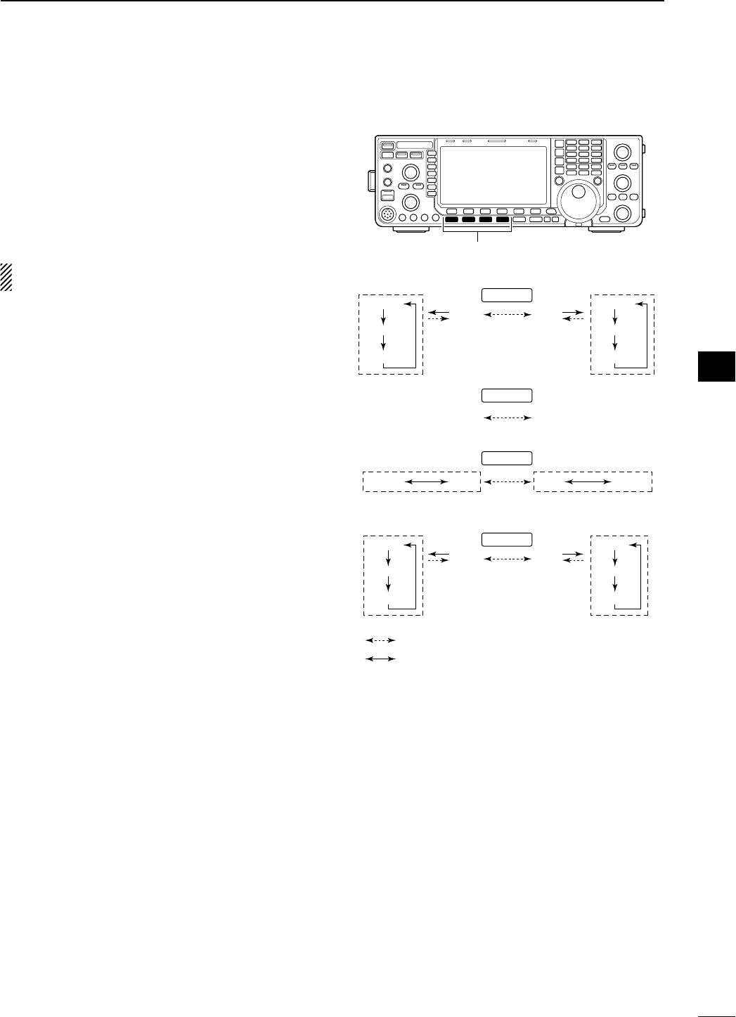
N Operating mode selection
SSB (USB/LSB), SSB data (USB data/LSB data),
CW, CW reverse (CW-R), RTTY, RTTY reverse
(RTTY-R), PSK, PSK reverse (PSK-R), AM, AM data,
FM and FM data modes are available in the IC-7600.
Push the desired mode switch momentarily to select
a mode of operation.
See the diagram as at right for the order of selection.
Microphone signals are muted when data mode is
selected.
• Selecting SSB mode
± Push [SSB] to select USB or LSB.
• USB is selected first when above 10 MHz; or LSB is
selected first when below 10 MHz operation.
• After USB or LSB is selected, push [SSB] to toggle
between USB and LSB.
• After USB or LSB is selected, push and hold [SSB] for
1 sec. to select USB or LSB data mode, respectively.
• After USB or LSB data mode is selected, push and hold
[SSB] for 1 sec. to select data 1, 2 and 3, in sequence.
• In USB or LSB data mode, push [SSB] to return to
USB or LSB mode, respectively.
• Selecting CW mode
± Push [CW] to select CW.
• After CW is selected, push [CW] to toggle between CW
and CW reverse mode.
• Selecting RTTY/PSK mode
± Push [RTTY/PSK] to select RTTY or PSK.
• After RTTY or PSK is selected, push [RTTY/PSK] to
toggle between RTTY and PSK.
• After RTTY or PSK is selected, push and hold
[RTTY/PSK] for 1 sec. to toggle between RTTY and
RTTY reverse, or, PSK and PSK reverse mode,
respectively.
• Selecting AM/FM mode
± Push [AM/FM] to select AM or FM.
• After AM or FM is selected, push [AM/FM] to toggle
between AM and FM.
• After AM or FM is selected, push and hold [AM/FM] for
1 sec. to select AM or FM data mode, respectively.
• After AM or FM data mode is selected, push and
hold [AM/FM] for 1 sec. to select data 1, 2 and 3, in
sequence.
• In AM or FM data mode, push [AM/FM] to return to AM
or FM mode, respectively.
Mode switches
USB
CW
AM
LSB
CW-R
RTTY-R RTTY PSK PSK-R
FM
USB-D1
USB-D2
USB-D3
LSB-D1
LSB-D2
LSB-D3
AM-D1
AM-D2
AM-D3
FM-D1
FM-D2
FM-D3
SSB
CW
RTTY/PSK
AM/FM
: Push mode switch momentary.
: Push and hold mode switch for 1 sec.
32
3
BASIC OPERATION
1
2
3
4
5
6
7
8
9
10
11
12
13
14
15
16
17
18
19
20
21
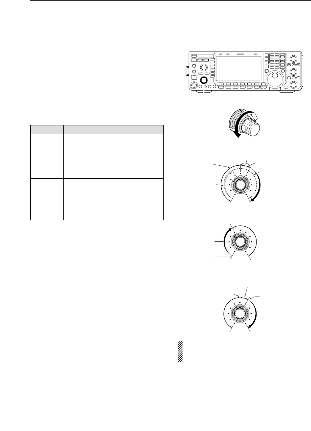
N Squelch and receive (RF) sensitivity
Adjusts the RF gain and squelch threshold level.
The squelch removes noise output from the speaker
(closed position) when no signal is received.
• The squelch is particularly effective for AM and FM. It is
also available for other modes.
• 12 to 1 o’clock position is recommended for any setting of
the [RF/SQL] control.
• The control can be set as ‘Auto’ (RF gain control in SSB,
CW, RTTY and PSK; squelch control in AM and FM) or
squelch control (RF gain is fixed at maximum) in set mode
as follows. (p. ??)
SET MODE OPERATION
RF+SQL
(default)
Can be used in all modes.
Functions as noise squelch or S-meter
squelch in FM modes; S-meter squelch
only in other modes.
SQL Operates as a squelch control.
• RF gain is fixed at maximum sensitivity.
AUTO
Operates as an RF gain control in
SSB, CW, RTTY and PSK modes.
• Squelch is fixed open.
Operates as a squelch control in AM
and FM modes.
• RF gain is fixed at maximum sensitivity.
M Adjusting RF gain (Receive sensitivity)
Normally, [RF/SQL] is set to the 11 o’clock position.
Rotate [RF/SQL] to the 11 o’clock position for maxi-
mum sensitivity.
• Rotating counterclockwise from the maximum position
reduces sensitivity.
• The S-meter indicates receive sensitivity.
M Adjusting squelch (Removing non-signal noise)
Rotate [RF/SQL] clockwise when receiving no signal,
until the noise just disappears.
• [RX] indicator light goes out.
• Rotating [RF/SQL] past the threshold point invokes the S-
meter squelch— this allows you to set a minimum signal
level needed to open the squelch.
[RF/SQL]
• When setting as RF gain/squelch control
Maximum
RF gain
S-meter
squelch
Noise squelch (FM mode)
Squelch is
open.
RF gain
adjustable
range
Recommended level
• When functioning as RF gain control
(Squelch is fixed open; SSB, CW, RTTY only)
Minimum RF gain
Adjustable
range
Maximum
RF gain
• When functioning as squelch control
(RF gain is fixed at maximum.)
Squelch is
open.
S-meter
squelch
S-meter squelch
threshold
Noise squelch
threshold
(FM mode)
Shallow Deep
Noise squelch (FM mode)
While rotating the RF gain control, noise may be
heard. This comes from the DSP unit and does not
indicate an equipment malfunction.
33
3BASIC OPERATION

N Volume setting
± Rotate [AF] control clockwise to increase, counter-
clockwise to decrease the audio output level.
Increases
Decreases
N Meter indication selection
The transceiver has 6 transmit meter functions for
your convenience.
± Push [METER] (MF2) several times to select the
desired meter.
Indicates the RF output power in watts.
Indicates the SWR on the transmission
line.
Indicates the ALC level. When the meter
movement shows the input signal level
exceeds the allowable level, the ALC
limits the RF power. In such cases,
reduce the [MIC GAIN] control.
Indicates the compression level when
the speech compressor is in use.
Indicates the drain current of the final
amplifier MOSFETs.
Indicates the drain terminal voltage of
the final amplifier MOSFETs.
D Multi-function digital meter
The IC-7600 can display the multi-function digital
meter on the LCD display. This meter displays all
transmit parameters simultaneously.
q Push and hold [METER] (MF2) for 1 sec. to turn
the multi-function digital meter ON.
w Push [P-HOLD] (F-1) to toggle the peak level hold
function ON.
• “ P-HOLD” appears on the window title when the peak
level hold function is ON.
e Push and hold [METER] (MF2) for 1 sec., or push
[EXIT/SET] to turn the multi-function digital meter
OFF.
[AF]
METER
SWR readout
ALC level readout
F-1
P-HOLD
METER
“P-HOLD” indicator
34
3
BASIC OPERATION
1
2
3
4
5
6
7
8
9
10
11
12
13
14
15
16
17
18
19
20
21
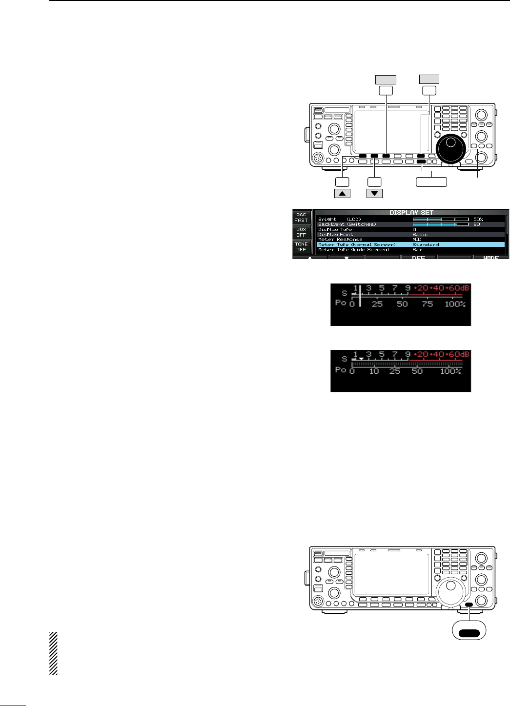
D Meter type selection
A total of 3 meter types are available in the IC-7600—
Standard, Edgewise and Bar meters.
Follow the instructions below for the meter type selec-
tion.
q Push [EXIT/SET] several times to return to normal
screen, if necessary.
w Push [SET] (F-6), then push [DISP] (F-3) to select
display set mode.
e Push [Y] (F-1) or [Z] (F-2) to select “Meter type
(Normal Screen)” item.
r Rotate the main dial to select the desired meter
type from “Standard,” “Edgewise” and “Bar.”
t Push [EXIT/SET] to exit display set mode.
N Voice synthesizer operation
The IC-7600 has a built-in voice synthesizer to
announce the operating frequency, mode* and S-
meter* in clear, electronically-generated voice, in
English (or Japanese).
Select the desired parameters to be announced, such
as audio level, speed, language, contents, in the set
mode in advance. (pgs. ??, ??)
± Push [SPEECH/LOCK] to announce the currently
selected frequency and S-meter level*.
± Push a mode switch to announce the appropriate
mode*.
* The S-meter level and operating mode announcements
can be deactivated, respectively. (pgs. ??, ??)
NOTE: When “LOCK/SPEECH” is selected in
[[SPEECH/LOCK] Switch] item in others set mode,
pushing and holding [SPEECH/LOCK] activates
the voice synthesizer. (p. ??)
Main dial
F-1 F-2
F-6
EXIT/SET
SET
F-3
DISP
• Edgewise meter
• Bar meter
SPEECH
LOCK
35
3BASIC OPERATION
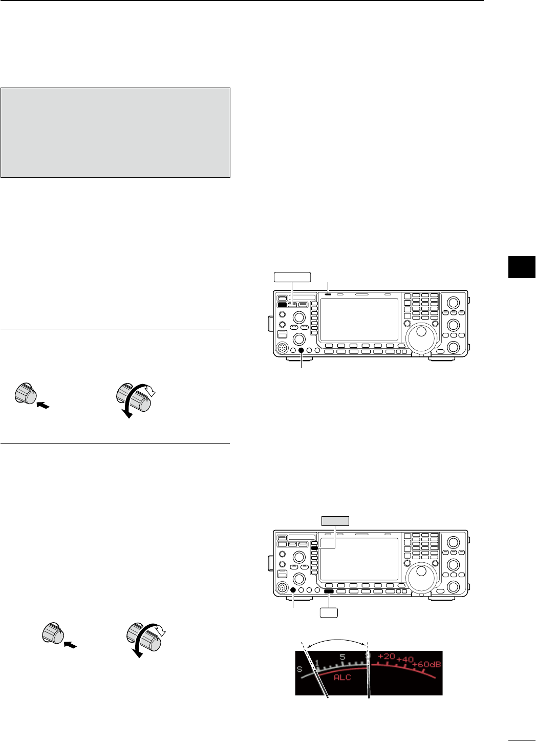
N Basic transmit operation
Before transmitting, monitor your selected
operating frequency to make sure transmitting
won’t cause interference to other stations on
the same frequency. It’s good amateur practice
to listen first, and then, even if nothing is heard,
ask “Is the frequency in use?” once or twice,
before you begin operating on that frequency.
D Transmitting
Before transmitting, monitor your selected operat-
ing frequency to make sure transmitting won’t cause
interference to other stations on the same frequency.
q Push [TRANSMIT] or [PTT] (microphone) to trans-
mit.
• The [TX] indicator lights red.
w Push [TRANSMIT] again or release [PTT] (micro-
phone) to return to receive.
Adjusting the transmit output power
± Rotate [RF POWER].
• Adjustable range : 2 W to 100 W
(AM mode: 1 W to 30 W)
Increases
max. 100 W
(30 W for AM)
Decreases
min. 2 W
(1 W for AM)
Push
D Microphone gain adjustment
Before transmitting, monitor your selected operat-
ing frequency to make sure transmitting won’t cause
interference to other stations on the same frequency.
q Push [SSB] to select SSB mode.
w Push [METER] (MF2) to select the ALC meter.
e Push [PTT] (microphone) to transmit.
• Talk into the microphone at your normal voice level.
r While talking into the microphone, rotate
[MIC GAIN] so that the ALC meter reading doesn’t
go outside the ALC zone. (see at right)
Increases
Decreases
Push
t Release [PTT] (microphone) to return to receive.
In addition, the transceiver can display the multi-func-
tion digital meter in the LCD, which displays all trans-
mit meters simultaneously.
[RF POWER]
TRANSMIT [TX] indicator
[MIC GAIN]
METER
SSB
ALC zone
36
3
BASIC OPERATION
1
2
3
4
5
6
7
8
9
10
11
12
13
14
15
16
17
18
19
20
21
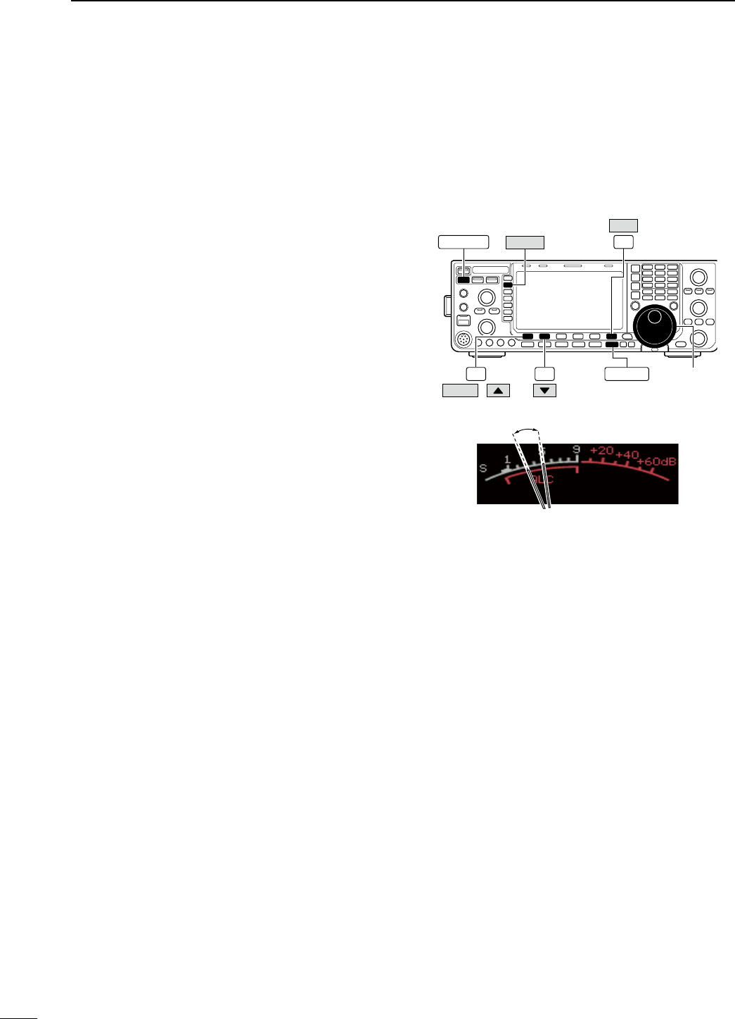
D Drive gain adjustment
The drive gain is active for all modes other than SSB
mode with speech compressor OFF.
Before transmitting, monitor your selected operat-
ing frequency to make sure transmitting won’t cause
interference to other stations on the same frequency.
q Push [EXIT/SET] several times to return to normal
screen, if necessary.
w Push [SET] (F-6), then push [LEVEL] (F-1) to
select level set mode.
e Push [Y] (F-1) or [Z] (F-2) to select “Drive Gain”
item.
r Push [METER] (MF2) to select the ALC meter.
t Push [PTT] (microphone; SSB with [COMP] ON,
AM or FM), key down (CW) or push [TRANSMIT]
(RTTY or PSK) to transmit.
y While talking into the microphone or keying down,
rotate the main dial so that the ALC meter reading
is within 30% to 50% of the ALC scale. (p. ??)
• Talk into the microphone at your normal voice level.
u Release [PTT], stop keying or push [TRANSMIT]
again to return to receive.
i Push [EXIT/SET] to exit display set mode.
Main dial
F-1 F-2
F-6
EXIT/SET
SET
METER
TRANSMIT
LEVEL /
Drive gain range
37
3BASIC OPERATION
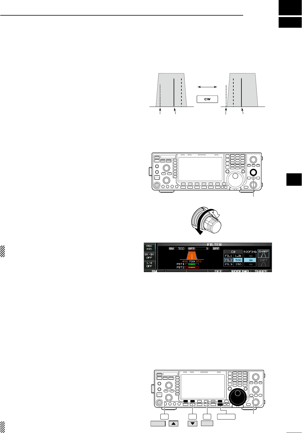
N Functions for CW operation
D About CW reverse mode
CW-R (CW Reverse) mode uses the opposite side
band to receive CW signals.
Use when interfering signals are near a desired sig-
nal and you want to use CW-R to reduce the interfer-
ence.
± During CW mode, push [CW] to select CW and
CW-R mode.
D About CW pitch control
The received CW audio pitch and CW side tone
can be adjusted to suit your preference (from 300
to 900 Hz in 5 Hz steps). This does not change the
operating frequency.
± Rotate [CW PITCH] to suit your preference.
• Adjustable within 300 to 900 Hz in 5 Hz steps.
The filter set screen graphically displays the CW
pitch operations. (See at right.)
D CW side tone function
When the transceiver is in receive (and the break-in
function is OFF— p. ??) you can listen to the CW side
tone without actually transmitting.
This allows you to match your transmit frequency
exactly to another station’s by matching the audio
tone. You can also use the CW side tone (be sure to
turn OFF break-in!) to practice CW sending.
CW side tone level can be adjusted in level set mode
(p. ??).
q Push [SET] (F-6), then push [LEVEL] (F-1) to
select level set mode.
w Push [Y] (F-1) or [Z] (F-2) to select “Side Tone
Level” item.
e Rotate the main dial to adjust the side tone level.
• Side tone level is adjustable within 0 to 100 % in 1%
steps.
r Push [EXIT/SET] to exit display set mode.
Matching the frequency of a transmitted and
received signal is called “Zero beat.”
Push
BFO
CW-R mode (USB side)
BFO
Desired signal
CW mode (LSB side)
Interference Desired signalInterference
[CW PITCH]
Lower frequency
Higher frequency
Main dial
F-1 F-2 F-6 EXIT/SET
SET
LEVEL /
4
38
RECEIVE AND TRANSMIT
1
2
3
4
5
6
7
8
9
10
11
12
13
14
15
16
17
18
19
20
21

D APF (Audio Peak Filter) operation
The APF changes the audio frequency response by
boosting a particular frequency to enhance a desired
CW signal.
q During CW mode, push [APF/TPF] to turn the
audio peak filter ON and OFF.
• “ ” appears in the display and the indicator on this
switch lights green when the audio peak filter is ON.
w Push and hold [APF/TPF] for 1 sec. several times
to select the desired audio filter width.
• WIDE, MID and NAR filters, or 320, 160 and 80 Hz fil-
ters are available depending on APF type setting in
other set mode. (p. ??)
The audio filter shape is also selectable from “SOFT”
and “SHARP” in others set mode (p. ??).
APF/TPF
39
4RECEIVE AND TRANSMIT
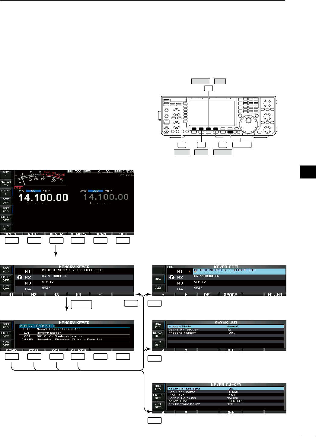
40
4
RECEIVE AND TRANSMIT
1
2
3
4
5
6
7
8
9
10
11
12
13
14
15
16
17
18
19
20
21
N Electronic keyer functions
The IC-7600 has a number of convenient functions
for the built-in electronic keyer that can be accessed
from the memory keyer menu.
q During CW mode, push [EXIT/SET] several times
to return to normal screen, if necessary.
w Push [KEYER] (F-3) to select memory keyer
screen.
e Push [EXIT/SET] to select memory keyer menu
screen.
r Push [SEND] (F-1), [EDIT] (F-2), [001] (F-3) or
[CW KEY] (F-4) to select the desired menu. See
the diagram below.
• Push [EXIT/SET] to return to the previous display. F-1 F-2 F-4
F-3
EXIT/SET
CW KEYEDITSEND
001KEYER /
• Memory keyer screen (p. ??)
• Memory keyer menu screen
• Memory keyer edit screen (p. ??)
• Contest number set mode (p. ??)
• Keyer set mode screen (p. ??)
F-1 F-2 F-3 F-4 F-5 F-6
F-1 F-2 F-3 F-4 F-5 F-6
F-1 F-2
F-3
F-4
EXIT/SET
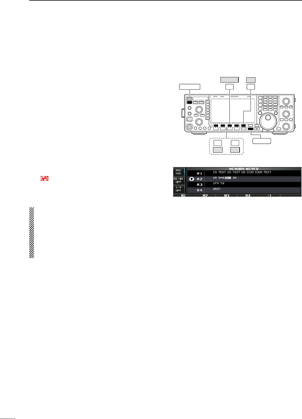
D Memory keyer screen
Pre-set characters can be sent using the keyer send
menu. Contents of the memory keyer are set using
the edit menu.
• Transmitting
q During CW mode operation, push [KEYER] (F-3)
to select memory keyer screen.
w Push [TRANSMIT] to set the transceiver to trans-
mit, or set the break-in function ON (p. ??).
e Push one of the function keys ([M1] (F-1) to [M4]
(F-4)) to send the contents of the memory keyer.
• Pushing and holding a function key for 1 sec. or push
[REPEAT] (F-6) while sending the contents of the
memory keyer to send the contents repeatedly; push
any function key except for to cancel the transmission.
• The contest serial number counter counts each time
the contents are sent.
• Push [−1] (F-5) to reduce the contest serial number
count by 1 before sending the contents of the memory
keyer to a station a second time.
• “M1”–“M4” are highlighted while transmitting.
•
“ ” appears while transmitting repeatedly.
• Set the repeat interval of the memory keyer to 1–60
sec. (1 sec. steps). See p. ?? for keyer set mode.
r Push [EXIT/SET] twice to return to normal screen.
For your information
When an external keypad is connected to [KEY] con-
nector on the rear panel, or one of [F-1]−[F-4] key of
the keyboard that is connected to the [USB] (A)
connector on the front panel is pushed, the pro-
grammed contents, M1—M4, can be transmitted
without selecting the memory keyer screen.
See pgs. ??, ?? for details.
F-3 F-5
EXIT/SET
−1
KEYER
TRANSMIT
F-4
M4
F-1
M1 —
• Memory keyer screen
41
4RECEIVE AND TRANSMIT
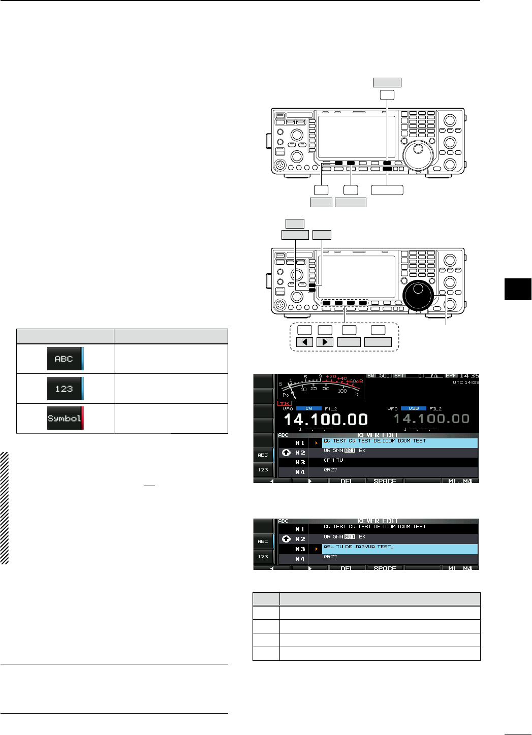
D Editing a memory keyer
The contents of the memory keyer memories can be
set using the memory keyer edit menu. The memory
keyer can memorize and re-transmit 4 CW key codes
for often-used CW sentences, contest serial numbers,
etc. Total capacity of the memory keyer is 70 charac-
ters per memory channel.
• Programming contents
q During CW mode operation, push [KEYER] (F-3)
to select memory keyer screen.
w Push [EXIT/SET] to select memory keyer menu,
then push [EDIT] (F-2) to select keyer edit screen.
• Memory keyer contents of Channel 1 (M1) is selected.
e Push [M1..M4] (F-6) several times to select the
desired memory keyer channel to be edited.
r Push [ABC] (MF6) or [123] (MF7) or [Symbol]
(MF7) to select the character group, then rotate the
main dial to select the character, or push the key-
pad for number input.
• [Symbol] appears when [123] (MF7) is pushed when
“123” character group is selected.
• Selectable characters (using the main dial);
Key selection Characters
A to Z (capital letters)
0 to 9 (numbers)
/ ? ^ . , @ 1
NOTE:
“^” is used to transmit a string of characters with no
inter-character space. Put “^” before a text string
such as ^AR, and the string “AR ” is sent with no
space.
“1” is used to insert the CW contest serial num-
ber. The serial number automatically increments by
1. This function is available only for one memory
keyer channel at a time. Memory keyer channel M2
used “1” by default.
t Push [Ω] (F-1) or [≈] (F-2) to move the cursor
backwards or forwards, respectively.
• Pushing [DEL] (F-3) deletes a character and [SPACE]
(F-4) inserts a space.
y Repeat steps r and t to input the desired char-
acters.
u Push [EXIT/SET] twice to return to normal screen.
For your convenience
When a PC keyboard is connected to
[USB] (A)
con-
nector on the front panel, the memory keyer contents
can also be edited from the keyboard.
F-2
F-6
EXIT/SET
EDIT
F-3
KEYER
M1..M4
F-1 F-2 F-4 Main dial
Symbol ABC
123
F-3
DEL SPACE
• Memory keyer edit screen
• Example— entered “QSL TU DE JA3YUA TEST”
into memory keyer channel 3
• Pre-programmed contents
CH Contents
M1
CQ TEST CQ TEST DE ICOM ICOM TEST
M2 UR 5NN1 BK
M3 CFM TU
M4 QRZ?
42
4
RECEIVE AND TRANSMIT
1
2
3
4
5
6
7
8
9
10
11
12
13
14
15
16
17
18
19
20
21
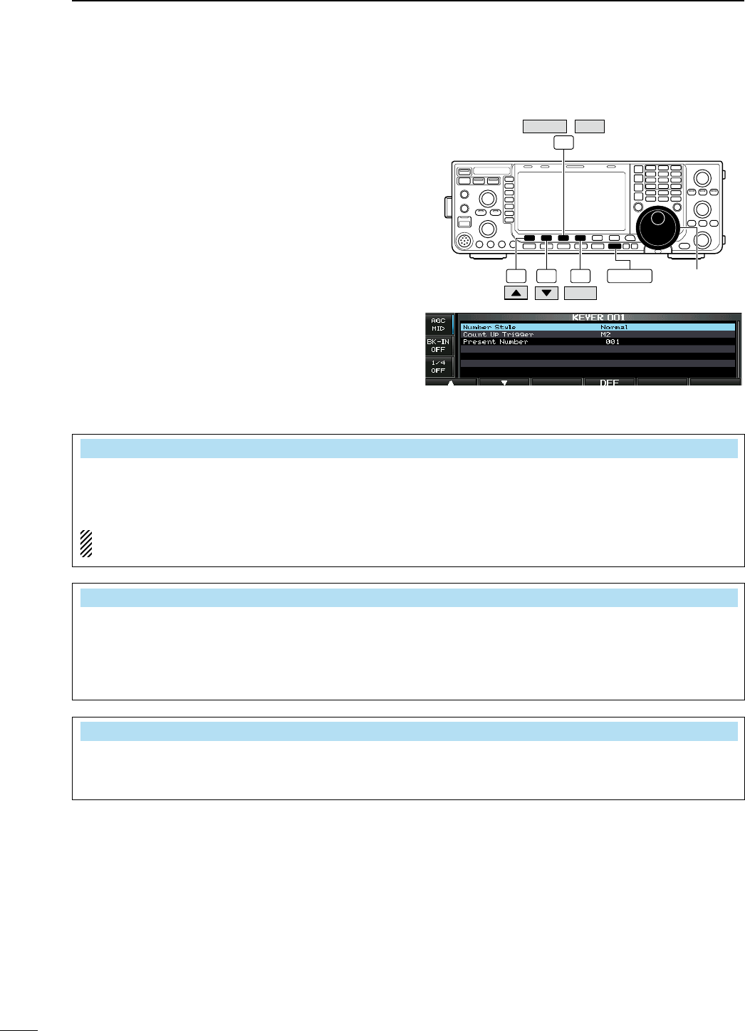
D Contest number set mode
This menu is used to set the contest (serial) number
and count-up trigger, etc.
• Setting contents
q During CW mode operation, push [KEYER] (F-3)
to select memory keyer screen.
w Push [EXIT/SET] to select memory keyer menu,
then push [001] (F-3) to select contest serial num-
ber set mode.
e Push [Y] (F-1) or [Z] (F-2) to select the desired
set item.
r Set the desired condition using the main dial.
• Push and hold [DEF] (F-4) for 1 sec. to select the
default condition or value.
t Push [EXIT/SET] twice to normal screen.
• Contest number set mode screen
Main dial
F-1 F-2 F-4 EXIT/SET
F-3
KEYER 001
/
DEF
Number Style Normal
This item sets the numbering system used for con-
test (serial) numbers— normal or short morse num-
bers.
Short morse numbers are also referred to as “cut”
numbers.
• Normal : Does not use short morse numbers
(default)
• 190ANO : Sets 1 as A, 9 as N and 0 as O.
• 190ANT : Sets 1 as A, 9 as N and 0 as T.
•
90 NO : Sets 9 as N and 0 as O.
•
90 NT : Sets 9 as N and 0 as T.
Count Up Trigger M2
This selects which of the four memories will con-
tain the contest serial number exchange. The
count-up trigger allows the serial number to auto-
matically increment after each complete serial num-
ber exchange is sent.
• M1, M2, M3 and M4 can be set. (default: M2)
Present Number 001
This item shows the current number for the count-up
trigger channel set above.
• Rotate the main dial to change the number, or
push and hold [001CLR] (F-4) for 1 sec. to reset
the current number to 001.
43
4RECEIVE AND TRANSMIT
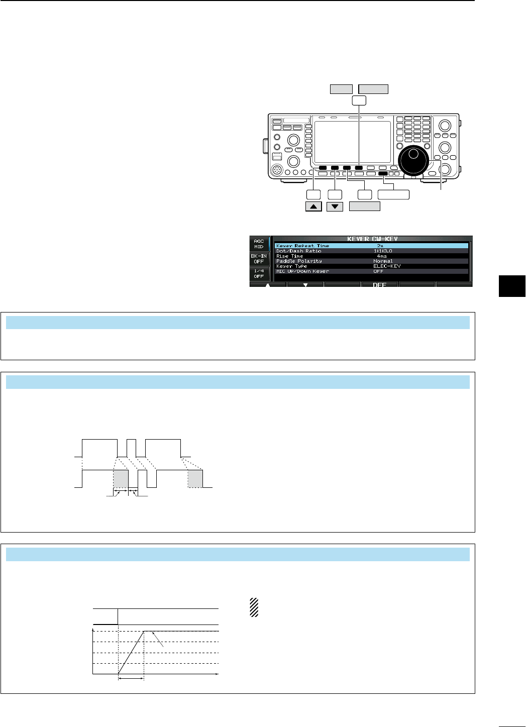
D Keyer set mode
This set mode is used to set the memory keyer repeat
time, dash weight, paddle specifications, keyer type,
etc.
• Setting contents
q During CW mode operation, push [KEYER] (F-3)
to select memory keyer screen.
w Push [EXIT/SET] to select memory keyer menu,
then push [CW KEY] (F-4) to select keyer set
mode.
e Push [Y] (F-1) or [Z] (F-2) to select the desired
set item.
r Set the desired condition using the main dial.
• Push and hold [DEF] (F-4) for 1 sec. to select the
default condition or value.
t Push [EXIT/SET] twice to normal screen.
Main dial
F-1 F-2 F-3 EXIT/SET
F-4
KEYER
CW KEY
/
DEF
• Keyer set mode screen
Keyer Repeat Time 2s
When sending CW using the repeat timer, this item
sets the time between transmission.
• 1 to 60 sec. in 1 sec. steps can be selected.
(default: 2 sec.)
Dot/Dash Ratio M2
This item sets the dot/dash ratio.
Keying weight example: Morse code “K”
DASH
Weight setting:
1:1:3 (default)
Weight setting:
Adjusted
DASH
DOT (fixed*)
Adjustable range SPACE (fixed*)
*SPACE and DOT length can be
adjusted with [KEY SPEED] only.
• 1:1:2.8 to 1:1:4.5 (in 0.1 steps) can be selected.
(default: 1:1:3.0)
Rise Time 4ms
This item sets the rise time of the transmitted CW
envelope.
Key action
Tx output power
• About rise time
Rise time
Tx
Rx
Set Tx power level
Time
0
• 2, 4, 6, 8 or 10 msec. can be selected.
(default: 4 msec.)
Key clicks on nearby frequencies can be generated
if the rise time of a CW waveform is too short.
Continues to the next page.
44
4
RECEIVE AND TRANSMIT
1
2
3
4
5
6
7
8
9
10
11
12
13
14
15
16
17
18
19
20
21

D Keyer set mode (continued)
Paddle Polarity Normal
This item sets the paddle dot-dash polarity. • Normal and reverse polarity can be selected.
Keyer Type ELE-KEY
This item selects the keyer type for [ELEC-KEY]
connector on the front panel.
• ELEC-KEY, BUG-KEY and Straight key can be
selected. (default: ELEC-KEY)
Mic Up/Down Keyer OFF
This item allows you to set the microphone [UP]/
[DN] keys to be used as a paddle.
• ON : [UP]/[DN] keys can be used for CW.
• OFF : [UP]/[DN] keys cannot be used for CW.
NOTE: When “ON” is selected, the frequency and
memory channel cannot be changed using
the [UP]/[DN] keys.
45
4RECEIVE AND TRANSMIT
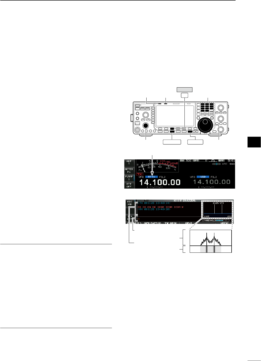
N RTTY (FSK) operation
A DSP-based high-quality Baudot RTTY encoder/
decoder is built-in to the IC-7600. When connecting
a PC keyboard (p. ??), RTTY operation can be per-
formed without an external RTTY terminal, TNC or
PC.
If you would rather use your RTTY terminal or TNC,
consult the manual that comes with the RTTY termi-
nal or TNC.
q Push a band key to select the desired band.
w Push [RTTY/PSK] to select RTTY.
• After RTTY mode is selected, push and hold
[RTTY/PSK] for 1 sec. to toggle between RTTY and
RTTY-R modes.
• “RTTY” or “RTTY-R” appears.
e Push [DECODE] (F-3) to display the decode
screen.
• The IC-7600 has a built-in Baudot decoder.
r To tune the desired signal, aim for a symmetrical
waveform and ensure the peak points align with
the mark (2125 Hz) and shift (170 Hz) frequency
lines in the FFT scope.
• The S-meter indicates received signal strength when
signal is received.
t Press [F12] on the connected PC’s keyboard to
transmit.
• [TX] indicator lights red.
y Type from the keyboard to enter the contents that
you want to transmit.
• The typewritten contents are indicated in the TX buffer
screen and transmitted immediately.
• The text color will be changed when transmitted.
• Press one of [F1]–[F8] on the keyboard to transmit the
TX memory contents.
u Press [F12] on the keyboard to return to receive.
For your convenience
The transmission contents can be typed before being
transmitted.
q Perform the steps q to r above.
w Type from the connected keyboard to enter the
message that you want to transmit.
• The typewritten contents are indicated in the TX buffer
screen.
e Press [F12] of the connected keyboard to transmit
the typewritten contents.
• The color of displayed text, in the TX buffer screen, will
be changed when transmitted.
• To cancel the transmission, press [F12] twice.
r Press [F12] of the keyboard to return to receive.
Main dial
EXIT/SET
F-3
[TX]
indicator
[RX]
indicator
[AF]
Band keys
RTTY/PSK
DECODE
Appears
2125/170
1905 2515
FFT scope
TX buffer screen
RX contents screen
Water-fall
46
4
RECEIVE AND TRANSMIT
1
2
3
4
5
6
7
8
9
10
11
12
13
14
15
16
17
18
19
20
21
D About RTTY reverse mode
Received characters are occasionally garbled when
the received signal is reversed between Mark and
Space tones. This reversal can be caused by incor-
rect TNC connections, setting, commands, etc.
To receive a reversed RTTY signals correctly, select
RTTY-R (RTTY Reverse) mode.
± During RTTY mode, push and hold [RTTY/PSK]
for 1 sec. to select RTTY and RTTY-R mode.
• Check the received signal.
D Twin peak filter
The twin peak filter changes the audio frequency
response by boosting the mark and space frequen-
cies (2125 and 2295 Hz) for better reception of RTTY
signals.
± During RTTY mode, push [APF/TPF] to turn the
twin peak filter ON and OFF.
• “ ” appears in the LCD and the indicator on
this switch lights green while the filter is in use.
NOTE: When the twin peak filter is in use, the
received audio output may increase. This is a nor-
mal, not a malfunction.
Normal Reverse
Space Mark BFO Space Mark
BFO
170 Hz 2125 Hz 170 Hz2125 Hz
APF/TPF
47
4RECEIVE AND TRANSMIT
D Functions for the RTTY decoder indication
q Push a band key to select the desired band.
w Push [RTTY/PSK] to select RTTY.
• After RTTY mode is selected, push and hold [RTTY/
PSK] for 1 sec. to toggle between RTTY and RTTY-R
modes.
• “RTTY” or “RTTY-R” appears.
e Push [DECODE] (F-3) to display the decode
screen.
• When tuned into an RTTY signal, decoded characters
are displayed in the RX contents screen.
r Push [HOLD/CLR] (F-2) to freeze the current
screen.
• “ ” appears while the function is in use.
• Push
[HOLD/CLR] (F-2) again to cancel the function.
t Push [WIDE] (F-6) to toggle the RTTY decode
screen size from normal and wide.
• S/RF meter type during wide screen indication can be
selected in display set mode. (pgs. ??, ??)
y Push and hold [HOLD/CLR] (F-2) for 1 sec. to
clear the displayed characters.
•
“ ” indicator disappears at the same time when
the hold function is in use.
u Push [EXIT/SET] to close the RTTY decode
screen.
D Setting the decoder threshold level
Adjust the RTTY decoder threshold level if some
characters are displayed when no signal is received.
q Select the RTTY decode screen as described
above.
w Push [ADJ] (F-4) to select the threshold level set-
ting condition.
e Rotate the main dial to adjust the RTTY decoder
threshold level.
• Push and hold [DEF] (F-5) for 1 sec. to select the
default setting.
r Push [ADJ] (F-4) to exit from the threshold level
setting condition.
The UnShift On Space (USOS) function and new
line code can be set in the RTTY set mode.
(p. ??)
EXIT/SET
F-3 F-6 Band keys
F-2 RTTY/PSK
DECODE
HOLD/CLR
WIDE
• Wide screen indication
48
4
RECEIVE AND TRANSMIT
1
2
3
4
5
6
7
8
9
10
11
12
13
14
15
16
17
18
19
20
21

D RTTY memory transmission
Pre-set characters can be sent using the RTTY mem-
ory. Contents of the memory are set using the edit
menu.
q
During RTTY mode operation, push [DECODE] (F-3)
to select RTTY decode screen.
w Push [TX MEM] (F-3) to select RTTY memory
screen.
e Push [1–4/5–8] (F-6) to select memory bank then
push one of the function keys ([RT1] (F-1) to
[RT4] (F-4) or [RT5] (F-1) to [RT8] (F-4)).
• When no keyboard is connected, the selected memory
contents will be transmitted immediately.
• When a keyboard is connected, the memory contents
will be transmitted immediately when function key is
pushed, or transmitted after [F12] on the connected
keyboard is pressed, depending on auto transmission/
reception setting (see below).
• The transmission date, time, reception date and/or time
may be displayed in RX contents screen, depending on
setting.
or
F-3 F-6
–
F-1 F-4
RT1 RT4 –
F-1 F-4
RT5 RT8
/
DECODE TX MEM 1–4/5–8
D Automatic transmission/reception setting
q
During RTTY mode operation, push [DECODE] (F-3)
to select RTTY decode screen.
w Push [TX MEM] (F-3) to select RTTY memory
screen, then push [EDIT] (F-5) to select RTTY
memory edit screen.
• RTTY memory contents of the Channel 1 (RT1) is
selected.
e Push [RT1..RT8] (F-6) several times to select the
desired RTTY memory.
r Push [AUTO TX] (F-5) several times to select the
desired condition as follow.
• AUTO TX/RX : Automatically transmits the
selected memory and returns to
receive after the transmission.
• AUTO TX : Automatically transmits the
selected memory. To return to
receive, press [F12] on the key-
board.
• AUTO RX : Press [F12] on the keyboard
to transmit the selected memory.
Automatically returns to receive
after the transmission.
• No indication : Press [F12] on the keyboard
to transmit the selected memory
and press [F12] again to return to
receive.
t Push [EXIT/SET] to exit RTTY memory edit condi-
tion.
NOTE: The transceiver always functions in the
“AUTO TX/RX” setting when no keyboard is con-
nected.
EXIT/SET
F-3 F-6
F-5
/
DECODE TX MEM
AUTO TXEDIT /
RT1..RT8
49
4RECEIVE AND TRANSMIT
D Editing RTTY memory
The contents of the RTTY memories can be set using
the memory edit menu. The memory can store and
re-transmit 8 RTTY message for often-used RTTY
information. Total capacity of the memory is 70 char-
acters per memory channel.
• Programming contents
q
During RTTY mode operation, push [DECODE] (F-3)
to select RTTY decode screen.
w Push [TX MEM] (F-3) to select RTTY memory
screen, then push [EDIT] (F-5) to select RTTY
memory edit screen.
• RTTY memory contents of the Channel 1 (RT1) is
selected.
e Push [RT1..RT8] (F-6) several times to select the
desired RTTY memory channel to be edited.
r Push [ABC] (MF6), [123] (MF7) or [Symbol] (MF7)
to select the character group, then rotate the main
dial to select the character, or push the keypad for
number input.
• [Symbol] (MF7) appears when [123] (MF7) is pushed
when “123” character group is selected.
• Selectable characters (using the main dial);
Key selection Characters
A to Z (capital letters)
0 to 9 (numbers)
! $ & ? " ’ – / . , : ; ( ) ↵
t Push [Ω] (F-1) or [≈] (F-2) to move the cursor
backwards or forwards, respectively.
• Pushing [DEL] (F-3) deletes a character and [SPACE]
(F-4) inserts a space.
y Repeat steps r and t to input the desired char-
acters.
u Push [EXIT/SET] to set the contents and exit
RTTY memory edit screen.
For your convenience
When a PC keyboard is connected to [USB] con-
nector on the front panel, the RTTY memory con-
tents can also be edited from the keyboard.
EXIT/SET
F-3 F-6
F-5
/
DECODE TX MEM
EDIT
RT1..RT8
F-1 F-2 F-4 Main dial
Symbol ABC
123
F-3
DEL SPACE
• RTTY memory edit screen
• Pre-programmed contents
CH Contents
RT1 ↵DE ICOM ICOM K↵
RT2 ↵DE ICOM ICOM ICOM K↵
RT3 ↵QSL UR 599–599 BK↵
RT4 ↵QSL DE ICOM ICOM UR 599–599 BK↵
RT5 ↵73 GL SK↵
RT6 ↵CQ CQ CQ DE ICOM ICOM ICOM K↵
RT7 ↵MY TRANSCEIVER IS IC–7600 & ANTENNA
IS A 3–ELEMENT TRIBAND YAGI.↵
RT8 ↵MY RTTY EQUIPMENT IS INTERNAL FSK
UNIT & DEMODULATOR OF THE IC–7600.↵
50
4
RECEIVE AND TRANSMIT
1
2
3
4
5
6
7
8
9
10
11
12
13
14
15
16
17
18
19
20
21
D RTTY decode set mode
This set mode is used to set the decode USOS func-
tion, time stamp setting, etc.
• Setting contents
q
During RTTY mode operation, push [DECODE] (F-3)
to select RTTY decode screen.
w Push [<MENU1>] (F-1) to select the second RTTY
decode menu, then push [SET] (F-5) to select
RTTY decode set mode.
• Push [WIDE] (F-6) to toggle the screen size from nor-
mal and wide.
e Push [Y] (F-1) or [Z] (F-2) to select the desired
set item.
r Set the desired condition using the main dial.
• Push and hold [DEF] (F-4) for 1 sec. to select a default
condition or value.
• Push [Ω ≈] (F-3) to select the set contents for some
items.
t Push [EXIT/SET] to exit from set mode.
F-1 F-2 F-4F-3
DEF
EXIT/SETF-3
F-6
F-1
F-5
Main dial
DECODE
<MENU1>
SET WIDE
• RTTY decode set mode screen
RTTY FFT Scope Averaging OFF
Select the FFT scope waveform averaging function
from 2 to 4 and OFF. (default: OFF)
Recommendation!
If you use the FFT scope waveform for tuning, use
of the default or smaller averaging setting is recom-
mended.
RTTY FFT Scope Waveform Color
51 153 255
Set the color for the FFT scope waveform.
• The color is set in RGB format.
•
The set color is indicated in the box beside the RGB
scale.
•
Push
[Ω ≈] (F-3)
to select R (Red), G (Green) and
B (Blue), and then rotate the main dial to set the
ratio from 0 to 255.
RTTY Decode USOS ON
Turn the capability of letter code decoding after
receiving a “space” (USOS; UnShift On Space func-
tion) ON and OFF.
• ON : Decode as letter code.
• OFF : Decode as character code.
RTTY Docode New Line Code CR,LF,CR+LF
Selects the new line code of the internal RTTY
decoder.
CR: Carriage Return, LF: Line Feed
• CR,LF,CR+LF : Makes new line with any codes.
• CR+LF : Makes new line with CR+LF code
only.
RTTY Diddle BLANK
Selects the diddle condition. • OFF : Turns the diddle function OFF.
• BLANK : Transmits blank code during no code
transmission.
• LTRS : Transmits letter code during no code
transmission.
51
4RECEIVE AND TRANSMIT
RTTY TX USOS ON
Explicitly inserts the FIGS character even though it
is not required by the receiving station.
• ON : Inserts FIGS.
• OFF : Does not insert FIGS.
RTTY Auto CR+LF by TX ON
Selects the automatic new line code (CR+LF) trans-
mission capability.
• ON : Transmits CR+LF code once.
• OFF : Transmits no CR+LF code.
RTTY Time Stamp ON
Turn the time stamp (date, transmission or reception
time) indication ON and OFF.
• ON : Displays the time stamp.
• OFF : No time stamp indication.
RTTY Time Stamp (Time) Local
Selects the clock indication for time stamp usage.
NOTE: The time won’t be displayed when “OFF” is
selected in “RTTY Time Stamp” as above.
• Local : Selects the time that set in “Time (Now).”
• UTC* : Selects the time that set in “CLOCK2.”
* The name of choice may differ according
to “CLOCK2 Name” setting (p. ??). “UTC”
is the default name of CLOCK2.
RTTY Time Stamp (Frequency) OFF
Selects the operating frequency indication for time
stamp usage.
NOTE: The frequency won’t be displayed when
“OFF” is selected in “RTTY Time Stamp” as above.
• ON : Displays the operating frequency.
• OFF : No operating frequency display.
RTTY Font Color (Receive)
128 255 128
Set the text color for received characters.
• The color is set in RGB format.
• The set color is indicated in the box beside the
RGB scale.
• Push [Ω ≈] (F-3) to select R (Red), G (Green) and
B (Blue), and then rotate the main dial to set the
ratio from 0 to 255.
RTTY Font Color (Transmit)
255 106 106
Set the text color for transmitted characters.
• The color is set in RGB format.
• The set color is indicated in the box beside the
RGB scale.
• Push [Ω ≈] (F-3) to select R (Red), G (Green) and
B (Blue), and then rotate the main dial to set the
ratio from 0 to 255.
RTTY Font Color (Time Stamp)
0155 189
Set the text color for time stamp indication.
• The color is set in RGB format.
• The set color is indicated in the box beside the
RGB scale.
• Push [Ω ≈] (F-3) to select R (Red), G (Green) and
B (Blue), and then rotate the main dial to set the
ratio from 0 to 255.
RTTY Font Color (TX Buffer)
255 255 255
Set the text color in the TX buffer screen.
• The color is set in RGB format.
• The set color is indicated in the box beside the
RGB scale.
• Push [Ω ≈] (F-3) to select R (Red), G (Green) and
B (Blue), and then rotate the main dial to set the
ratio from 0 to 255.
52
4
RECEIVE AND TRANSMIT
1
2
3
4
5
6
7
8
9
10
11
12
13
14
15
16
17
18
19
20
21
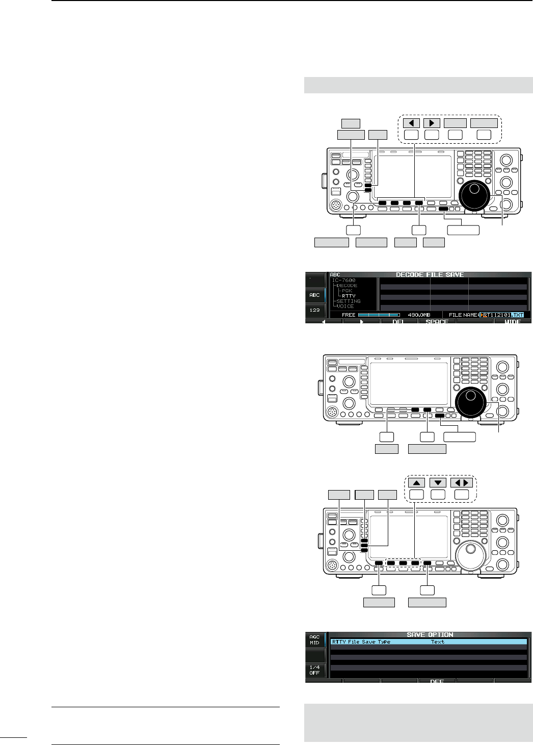
D Data saving
The contents of the RTTY memory/received signal
can be saved into the USB-Memory.
q During RTTY decode screen indication, push
[<MENU1>] (F-1) to select the RTTY decode sec-
ond menu.
w
Push [SAVE] (F-4) to select decode file save screen.
e Change the following conditions if desired.
• File name:
z Push [EDIT] (F-4) to select file name edit con-
dition.
• Push [DIR/FILE] (F-1) several times to select the
file name, if necessary.
x Push [ABC] (MF6), [123] or [Symbol] (MF7)
to select the character group, then rotate the
main dial to select the character.
• [ABC] (MF6): A to Z (capital letters); [123] (MF7):
0 to 9 (numerals); [Symbol] (MF7): ! # $ % & ’ ` ^
– ( ) { } _ _ @ can be selected.
• Push [Ω] (F-1) to move the cursor left, push
[≈] (F-2) to move the cursor right, [DEL] (F-3)
delete a character and push [SPACE] (F-4) to
insert a space.
c Push [EXIT/SET] to set the file name.
• File format
z Push and hold [SAVE/OPT] (F-5) for 1 sec. to
enter save option screen.
x Rotate the main dial to select the saving for-
mat from Text to HTML.
• “Text” is the default setting.
• Push and hold [DEF] (F-4) for 1 sec. to select the
default setting.
c Push [EXIT/SET] to return to the previous
indication.
• Saving location
z Push [DIR/FILE] (F-1) to select tree view
screen.
x Select the desired directory or folder in the
USB-Memory.
• Push [Ω ≈] (F-4) to select the upper directory.
• Push [Y] (F-2) or [Z] (F-3) to select folder in the
same directory.
• Push and hold [Ω ≈] (F-4) for 1 sec. to select a
folder in the directory.
• Push
[REN] (MF5) to rename the folder.
• Push and hold [DEL] (MF6) for 1 sec. to delete
the folder.
• Push and hold [MAKE] (MF7) for 1 sec. to mak-
ing a new folder. (Edit the name with the same
manner as the “• File name” above.)
c Push [DIR/FILE] (F-1) twice to select the file
name.
r Push [SAVE/OPT] (F-5).
• After saving is completed, returns to RTTY decode sec-
ond menu automatically.
For your convenience!
Two data formats, Text and HTML, are available for
PC data storage.
The USB-Memory is not supplied by Icom.
F-1 F-2 F-4F-3
DEL SPACE
F-1 F-4 EXIT/SET Main dial
Symbol ABC
123
SAVE EDIT
/
DIR/FILE
<MENU1> /
• Decode file save screen— file name edit
F-4 EXIT/SET Main dial
F-5
SAVE/OPT
DEF
F-1 F-5
SAVE/OPT
F-4
F-2 F-3
DIR/FILE
REN DEL
MAKE
• Save option screen
When a PC keyboard is connected to [USB] connector
on the front panel, the file name can also be edited from
the keyboard. In this case, a USB hub is required.
53
4RECEIVE AND TRANSMIT
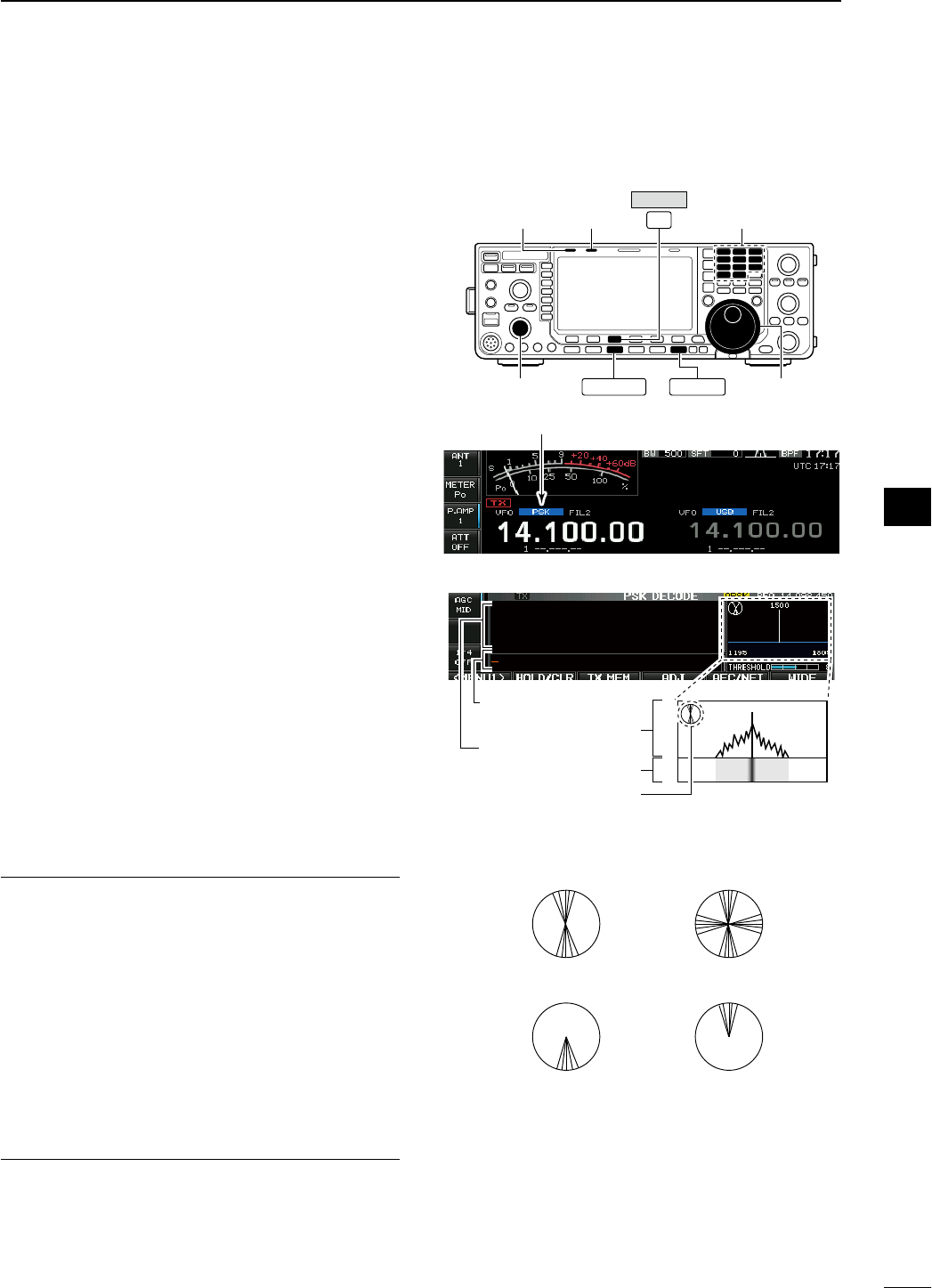
N PSK operation
A high-quality DSP-based PSK encoder/decoder is
built-in to the IC-7600. When connecting a PC key-
board (p. ??), PSK operation can be performed with-
out PSK software installed on your PC.
If desired, you can also use your PSK software; con-
sult the manual that comes with the software.
q Push a band key to select the desired band.
w Push [RTTY/PSK] to select PSK.
• After PSK mode is selected, push and hold
[RTTY/PSK] for 1 sec. to toggle between PSK and
PSK-R modes.
• “PSK” or “PSK-R” appears.
e
Push
[DECODE] (F-3)
to display the decode
screen.
• The IC-7600 has a built-in PSK decoder.
r Tune to the desired signal with the main dial.
• The signal is properly tuned when the radiated lines
in the vector tuning indicator narrow, as show in the
example below.
• The radiated lines in the vector tuning indicator may be
displayed sporadically.
• When a PSK signal is received, the water-fall display is
activated.
•
The water-fall display shows the signals within the pass-
band. Received PSK signals appear as vertical lines.
t Press [F12] of the connected keyboard to transmit.
• [TX] indicator lights red.
y Type from the connected keyboard to enter the
message that you want to transmit.
• The typewritten contents are indicated in the TX buffer
screen and transmitted immediately.
• The text color will be changed when transmitted.
• Press one of [F1]–[F8] to transmit the TX memory con-
tents.
u Press [F12] of the keyboard to return to receive.
For your convenience
The transmission contents can be typed before being
transmitted.
q Perform the steps q to r above.
w Type from the connected keyboard to enter the
message that you want to transmit.
• The message is shown in the TX buffer screen.
e Press [F12] of the connected keyboard to transmit
the message.
• The color of displayed text, in the TX buffer screen, will
be changed when transmitted.
• To cancel the transmission, press [F12] twice.
r Press [F12] of the keyboard to return to receive.
Main dial
EXIT/SET
F-3
[TX]
indicator
[RX]
indicator
[AF]
Band keys
RTTY/PSK
DECODE
Appears
1500
1195 1805
Vector tuning indicator
FFT scope
TX buffer screen
RX contents screen
Water-fall
• Vector tuning indicator indication example
Tuned BPSK signal
BPSK/QPSK idle signal Unmodulated signal
Tuned QPSK signal
54
4
RECEIVE AND TRANSMIT
1
2
3
4
5
6
7
8
9
10
11
12
13
14
15
16
17
18
19
20
21
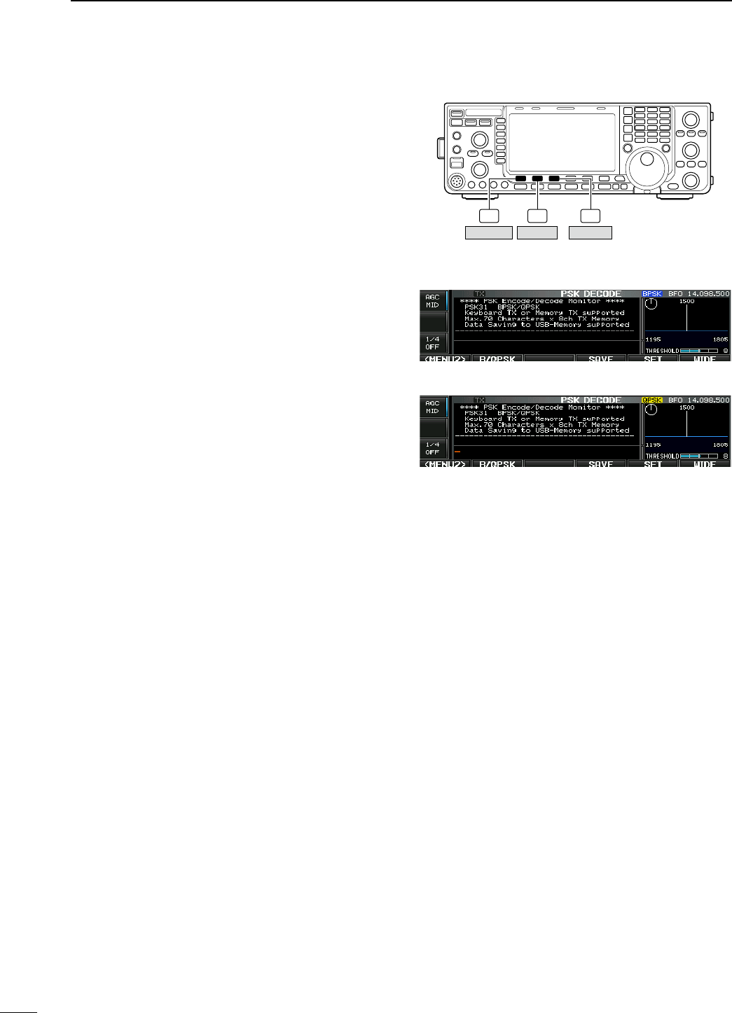
D About BPSK and QPSK modes
BPSK and QPSK modes are available for PSK.
• BPSK (Binary Phase Shift Keying) mode is the most
commonly used mode.
• QPSK (Quadrature Phase Shift Keying) mode has
error correction capability to provide better decoding
than BPSK mode in marginal condition. However,
more accurate tuning is required with QPSK mode,
due to the tight phase margin of QPSK.
q During PSK mode selection, push [DECODE] (F-3)
to display the PSK decode screen.
w Push [<MENU1>] (F-1) to select PSK decode sec-
ond menu.
e Push [B/QPSK] (F-2) to toggle between BPSK and
QPSK mode alternately.
F-2 F-3F-1
DECODE
B/QPSK<MENU1>
• PSK decode screen— BPSK mode
• PSK decode screen— QPSK mode
55
4RECEIVE AND TRANSMIT
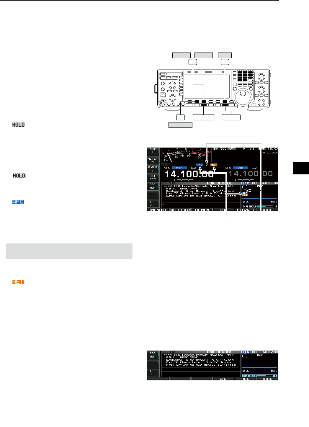
D Functions for the PSK decoder indication
q Push a band key to select the desired band.
w Push [RTTY/PSK] to select PSK.
• After PSK mode is selected, push and hold [RTTY/
PSK] for 1 sec. to toggle between PSK and PSK-R
modes.
• “PSK” or “PSK-R” appears.
e Push [DECODE] (F-3) to display the decode
screen.
• When tuned into a PSK signal, decoded characters are
displayed in the RX contents screen.
r Push [HOLD/CLR] (F-2) to freeze the current
screen.
• “ ” appears while the function is in use.
• Push
[HOLD/CLR] (F-2) again to release the function.
t Push [WIDE] (F-6) to toggle the PSK decode
screen size from normal and wide.
• S/RF meter type during wide screen indication can be
selected in display set mode. (pgs. ??, ??)
y Push and hold [HOLD/CLR] (F-2) for 1 sec. to
clear the displayed characters.
•
“ ” indicator disappears at the same time when
the hold function is in use.
u Push [AFC/NET] (F-3) to turn the AFC function
ON.
• “ ” appears.
• If a PSK signal is received within the AFC tuning range,
the decoder automatically tunes into the signal and the
offset frequency is displayed.
• The AFC tuning range is set to ±15 Hz as the default.
Optional ±8 Hz setting is available in PSK decode set
mode. (p. ??)
NOTE: The AFC function may not tune the signal
properly when a weak PSK signal is received.
i Push [AFC/NET] (F-3) again to turn the NET func-
tion ON.
• “ ” appears additionally.
o Push and hold [AFC/NET] (F-3) for 1 sec. to add
the offset frequency to the displayed frequency.
!0 Push [EXIT/SET] to close the PSK decode screen.
D Setting the decoder threshold level
Adjust the PSK decoder threshold level if some char-
acters are displayed when no signal is received.
q Call up the PSK decode screen as described
above.
w Push [ADJ] (F-4) to select the threshold level set-
ting condition.
e Rotate the main dial to adjust the PSK decoder
threshold level.
• Push and hold [DEF] (F-5) for 1 sec. to select the
default setting.
r Push [ADJ] (F-4) to exit from the threshold level
setting condition.
EXIT/SET
F-3 F-6 Band keys
F-2 RTTY/PSK
HOLD/CLR
WIDE
/
DECODE AFC/NET
• AFC/NET indications
“AFC” and “NET”
indicators
Offset frequency
56
4
RECEIVE AND TRANSMIT
1
2
3
4
5
6
7
8
9
10
11
12
13
14
15
16
17
18
19
20
21
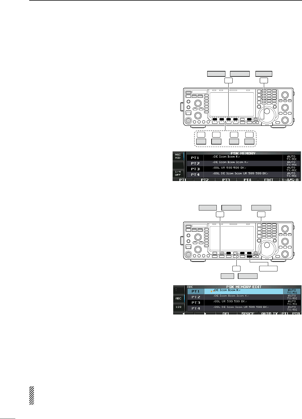
D PSK memory transmission
Pre-set characters can be sent using the PSK mem-
ory. Contents of the memory are set using the edit
menu.
q
During PSK mode operation, push [DECODE] (F-3)
to select PSK decode screen.
w Push [TX MEM] (F-3) to select PSK memory
screen.
e Push [1–4/5–8] (F-6) to select memory bank
then push one of the function keys ([PT1] (F1) to
[PT4] (F-4) or [PT5] (F-1) to [PT8] (F-4)).
• When no keyboard is connected, the selected memory
contents will be transmitted immediately.
• When a keyboard is connected, the memory contents
will be transmitted immediately when function key is
pushed, or transmitted after [F12] on the connected
keyboard is pressed, depending on auto transmission/
reception setting (see below).
• The transmission date, time, reception date and/or time
may be displayed in RX contents screen, depending on
setting.
or
F-3 F-6
–
F-1 F-4
PT1 PT4 –
F-1 F-4
PT5 PT8
/
DECODE TX MEM 1–4/5–8
D Automatic transmission/reception setting
q
During PSK mode operation, push [DECODE] (F-3)
to select PSK decode screen.
w Push [TX MEM] (F-3) to select PSK memory
screen, then push [EDIT] (F-5) to select PSK mem-
ory edit screen.
• PSK memory contents of Channel 1 (PT1) is selected.
e Push [PT1..PT8] (F-6) several times to select the
desired PSK memory.
r Push [AUTO TX] (F-5) several times to select the
desired condition, as follows.
• AUTO TX/RX : Automatically transmits the
selected memory and returns to
receive after the transmission.
• AUTO TX : Automatically transmits the
selected memory. To return to
receive, press [F12] on the key-
board.
• AUTO RX : Press [F12] on the keyboard
to transmit the selected memory.
Automatically returns to receive
after the transmission.
• No indication : Press [F12] on the keyboard
to transmit the selected memory
and press [F12] again to return to
receive.
t Push [EXIT/SET] to return to exit from PSK mem-
ory edit condition.
NOTE: The transceiver always functions in the
“AUTO TX/RX” setting when no keyboard is con-
nected.
EXIT/SET
F-3 F-6
F-5
/
DECODE TX MEM
AUTO TXEDIT /
PT1..PT8
57
4RECEIVE AND TRANSMIT
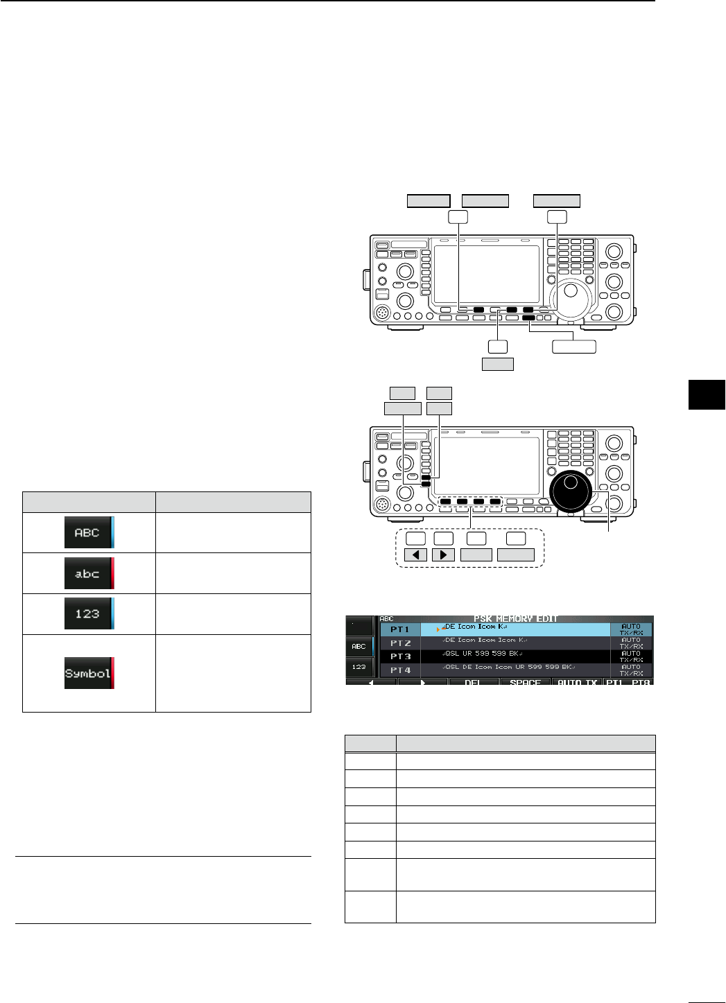
D Editing PSK memory
The contents of the PSK memories can be set using
the memory edit menu. The memory can store and
re-transmit 8 PSK message for often-used PSK infor-
mation. Total capacity of the memory is 70 characters
per memory channel.
• Programming contents
q
During PSK mode operation, push [DECODE] (F-3)
to select PSK decode screen.
w Push [TX MEM] (F-3) to select
PSK
memory
screen, then push [EDIT] (F-5) to select
PSK
mem-
ory edit screen.
• PSK memory contents of the Channel 1 (PT1) is
selected.
e Push [PT1..PT8] (F-6) several times to select the
desired PSK memory channel to be edited.
r Push [ABC] (MF6), [abc] (MF6), [123] (MF7) or
[Symbol] (MF7) to select the character group, then
rotate the main dial to select the character, or push
the keypad for number input.
• [abc] (MF6) appears when [ABC] (MF6) is pushed
when “ABC” character group is selected. and [Symbol]
(MF7) appears when [123] (MF7) is pushed when
“123” character group is selected.
• Selectable characters (using the main dial);
Key selection Characters
A to Z (capital letters)
a to z (small letters)
0 to 9 (numbers)
! # $ % & ¥ ? " ’ ` ^ + – 1
/ . , : ; = < > ( ) [ ] { } ¦ _
_ @ ↵
( “↵” is for the memory con-
tents setting only.)
t Push [Ω] (F-1) or [≈] (F-2) to move the cursor
backwards or forwards, respectively.
• Pushing [DEL] (F-3) deletes a character and [SPACE]
(F-4) inserts a space.
y Repeat steps r and t to input the desired char-
acters.
u Push [EXIT/SET] to set the contents and exit
PSK
memory edit screen.
For your convenience
When a PC keyboard is connected to [USB] con-
nector on the front panel, the
PSK
memory con-
tents can also be edited from the keyboard.
EXIT/SET
F-3 F-6
F-5
/
DECODE TX MEM
EDIT
PT1..PT8
F-1 F-2 F-4 Main dial
Symbol ABC
123
F-3
DEL SPACE
abc
• PSK memory edit screen
• Pre-programmed contents
CH Contents
PT1 ↵DE Icom Icom K↵
PT2 ↵DE Icom Icom Icom K↵
PT3 ↵QSL UR 599 599 BK↵
PT4 ↵QSL DE Icom Icom UR 599 599 BK↵
PT5 ↵73 GL SK↵
PT6 ↵CQ CQ CQ DE Icom Icom Icom K↵
PT7 ↵My transceiver is IC–7600 & Antenna is a 3–
element triband yagi.↵
PT8 ↵My PSK equipment is internal modulator &
demodulator of the IC–7600.↵
58
4
RECEIVE AND TRANSMIT
1
2
3
4
5
6
7
8
9
10
11
12
13
14
15
16
17
18
19
20
21
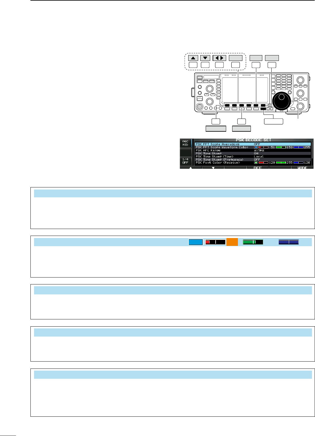
D PSK decode set mode
This set mode is used to set the decode USOS func-
tion, time stamp setting, etc.
• Setting contents
q
During PSK mode operation, push [DECODE] (F-3)
to select PSK decode screen.
w Push [<MENU1>] (F-1) to select the second
PSK
decode menu, then push [SET] (F-5) to select
PSK
decode set mode.
• Push [WIDE] (F-6) to toggle the screen size from nor-
mal and wide.
e Push [Y] (F-1) or [Z] (F-2) to select the desired
set item.
r Set the desired condition using the main dial.
• Push and hold [DEF] (F-4) for 1 sec. to select a default
condition or value.
• Push [Ω ≈] (F-3) to select the set contents for some
items.
t Push [EXIT/SET] to exit from set mode.
F-1 F-2 F-4F-3
DEF
EXIT/SETF-3
F-6
F-1
F-5
Main dial
DECODE
<MENU1>
SET WIDE
PSK FFT Scope Averaging OFF
Select the FFT scope waveform averaging function
from 2 to 4 and OFF. (default: OFF)
Recommendation!
If you use the FFT scope waveform for tuning, using
the default or smaller averaging setting is recom-
mended.
PSK FFT Scope Waveform Color
51 153 255
Set the color for the FFT scope waveform.
• The color is set in RGB format.
•
The set color is indicated in the box beside the RGB
scale.
•
Push
[Ω ≈] (F-3)
to select R (Red), G (Green) and
B (Blue), and then rotate the main dial to set the
ratio from 0 to 255.
PSK AFC Range ±15Hz
Select the AFC (Automatic Frequency Control)
function operating range from ±15 Hz (default) and
±8 Hz.
NOTE: The AFC function may not tune the signal
properly when a weak PSK signal is received.
PSK Time Stamp ON
Turn the time stamp (date, transmission or reception
time) display ON and OFF.
• ON : Displays the time stamp.
• OFF : No time stamp display.
PSK Time Stamp (Time) Local
Selects the clock display for time stamp usage.
NOTE: The time won’t be displayed when “OFF” is
selected in “PSK Time Stamp” as above.
• Local : Selects the time that set in “Time (Now).”
• UTC* : Selects the time that set in “CLOCK2.”
* The name of choice may differ according to
“CLOCK2 Name” setting (p. ??). “UTC” is the
default name of CLOCK2.
59
4RECEIVE AND TRANSMIT
PSK Time Stamp (Frequency) OFF
Selects the operating frequency display for time
stamp usage.
NOTE: The frequency won’t be displayed when
“OFF” is selected in “PSK Time Stamp” as
below left.
• ON : Displays the operating frequency.
• OFF : No operating frequency display.
PSK Font Color (Receive)
128 255 128
Set the text color for received characters.
• The color is set in RGB format.
•
The set color is indicated in the box beside the RGB
scale.
•
Push
[Ω ≈] (F-3)
to select R (Red), G (Green) and
B (Blue), and then rotate the main dial to set the
ratio from 0 to 255.
PSK Font Color (Transmit)
255 106 106
Set the text color for transmitted characters.
• The color is set in RGB format.
•
The set color is indicated in the box beside the RGB
scale.
•
Push
[Ω ≈] (F-3)
to select R (Red), G (Green) and
B (Blue), and then rotate the main dial to set the
ratio from 0 to 255.
PSK Font Color (Time Stamp)
0155 189
Set the text color for time stamp indication.
• The color is set in RGB format.
•
The set color is indicated in the box beside the RGB
scale.
•
Push
[Ω ≈] (F-3)
to select R (Red), G (Green) and
B (Blue), and then rotate the main dial to set the
ratio from 0 to 255.
PSK Font Color (TX Buffer)
255 255 255
Set the text color in the TX buffer screen.
• The color is set in RGB format.
•
The set color is indicated in the box beside the RGB
scale.
•
Push
[Ω ≈] (F-3)
to select R (Red), G (Green) and
B (Blue), and then rotate the main dial to set the
ratio from 0 to 255.
60
4
RECEIVE AND TRANSMIT
1
2
3
4
5
6
7
8
9
10
11
12
13
14
15
16
17
18
19
20
21

D Data saving
The contents of the PSK memory/received signal can
be saved into the USB-Memory.
q During PSK decode screen indication, push
[<MENU1>] (F-1) to select the PSK decode sec-
ond menu.
w
Push [SAVE] (F-4) to select decode file save screen.
e Change the following conditions if desired.
• File name:
z Push [EDIT] (F-4) to select file name edit con-
dition.
• Push [DIR/FILE] (F-1) several times to select the
file name, if necessary.
x Push [ABC] (MF6), [123] or [Symbol] (MF7)
to select the character group, then rotate the
main dial to select the character.
• [ABC] (MF6): A to Z (capital letters); [123] (MF7):
0 to 9 (numerals); [Symbol] (MF7): ! # $ % & ’ ` ^
– ( ) { } _ ~ @ can be selected.
• Push [Ω] (F-1) to move the cursor left, push
[≈] (F-2) to move the cursor right, [DEL] (F-3)
delete a character and push [SPACE] (F-4) to
insert a space.
c Push [EXIT/SET] to set the file name.
• File format
z Push and hold [SAVE/OPT] (F-5) for 1 sec. to
enter save option screen.
x Rotate the main dial to select the saving for-
mat from Text to HTML.
• “Text” is the default setting.
• Push and hold [DEF] (F-4) for 1 sec. to select the
default setting.
c Push [EXIT/SET] to return to the previous
indication.
• Saving location
z Push [DIR/FILE] (F-1) to select tree view
screen.
x Select the desired directory or folder in the
USB-Memory.
• Push [Ω ≈] (F-4) to select the upper directory.
• Push [Y] (F-2) or [Z] (F-3) to select folder in the
same directory.
• Push and hold [Ω ≈] (F-4) for 1 sec. to select a
folder in the directory.
• Push
[REN] (MF5) to rename the folder.
• Push and hold [DEL] (MF6) for 1 sec. to delete
the folder.
• Push and hold [MAKE] (MF7) for 1 sec. to mak-
ing a new folder. (Edit the name with the same
manner as the “• File name” above.)
c Push [DIR/FILE] (F-1) twice to select the file
name.
r Push [SAVE/OPT] (F-5).
• After saving is completed, returns to PSK decode sec-
ond menu automatically.
For your convenience!
Two data formats, Text and HTML, are available for
PC data storage.
The USB-Memory is not supplied by Icom.
F-1 F-2 F-4F-3
DEL SPACE
F-1 F-4 EXIT/SET Main dial
Symbol ABC
123
SAVE EDIT
/
DIR/FILE
<MENU1> /
• Decode file save screen— file name edit
F-4 EXIT/SET Main dial
F-5
SAVE/OPT
DEF
F-1 F-5
SAVE/OPT
F-4
F-2 F-3
DIR/FILE
REN DEL
MAKE
• Save option screen
When a PC keyboard is connected to [USB] connector
on the front panel, the file name can also be edited from
the keyboard. In this case, a USB hub is required.
61
4RECEIVE AND TRANSMIT
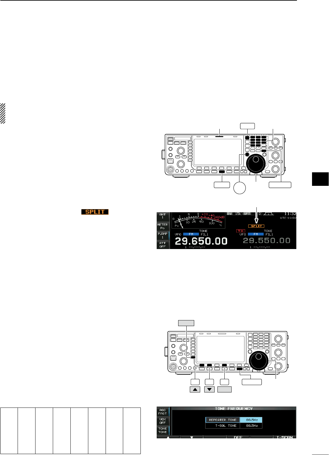
N Repeater operation
A repeater retransmits a received signal on a differ-
ent frequency. When using a repeater, the transmit
frequency is shifted from the receive frequency by an
offset frequency. A repeater can be accessed using
split frequency operation with the transmit frequency
shifted to the repeater's receive frequency.
For accessing a repeater which requires an access
tone, set the tone frequency in tone frequency set
mode as described below.
q Set the offset frequencies (HF, 50 MHz) and turn
ON the quick split function in Others set mode in
advance. (pgs. ??, ??)
w Push [VFO/MEMO] to select VFO mode.
e Push the desired band key.
r Push [AM/FM] several times to select FM mode.
t Set the receive frequency (repeater output fre-
quency).
y Push and hold [SPLIT] for 1 sec. to start repeater
operation.
• Repeater tone is turned ON automatically.
• [SPLIT] indicator lights and “ ” appears on
the LCD.
• Shifted transmit frequency and “TX” appear in the sub
band.
• The transmit frequency can be monitored while push-
ing [XFC].
u Push and hold [PTT] to transmit; release [PTT] to
receive.
i To return to simplex, push [SPLIT] momentarily.
D Repeater access tone frequency setting
Some repeaters require subaudible tones to be
accessed. Subaudible tones are superimposed on
your normal signal and must be set in advance. The
transceiver has 50 tones from 67.0 Hz to 254.1 Hz.
q During FM mode operation, push and hold [TONE]
(MF7) for 1 sec. to enter tone frequency set mode.
w Push [Y] (F-1) or [Z] (F-2) to select REPEATER
TONE item.
e Rotate the main dial to select the desired repeater
tone frequency.
• Push and hold [DEF] (F-4) for 1 sec. to select the
default setting.
r
Push [EXIT/SET] to return to the previous indication.
• Available tone frequencies (unit: Hz)
67.0
69.3
71.9
74.4
77.0
79.7
82.5
85.4
088.5
091.5
094.8
097.4
100.0
103.5
107.2
110.9
114.8
118.8
123.0
127.3
131.8
136.5
141.3
146.2
151.4
156.7
159.8
162.2
165.5
167.9
171.3
173.8
177.3
179.9
183.5
186.2
189.9
192.8
196.6
199.5
203.5
206.5
210.7
218.1
225.7
229.1
233.6
241.8
250.3
254.1
Main
dial
[SPLIT]
indicator Band keys
AM/FM
SPLIT
VFO/MEMO
XFC
Appears
F-4 EXIT/SET Main dial
F-2F-1
DEF
TONE
• Tone frequency set mode
62
4
RECEIVE AND TRANSMIT
1
2
3
4
5
6
7
8
9
10
11
12
13
14
15
16
17
18
19
20
21
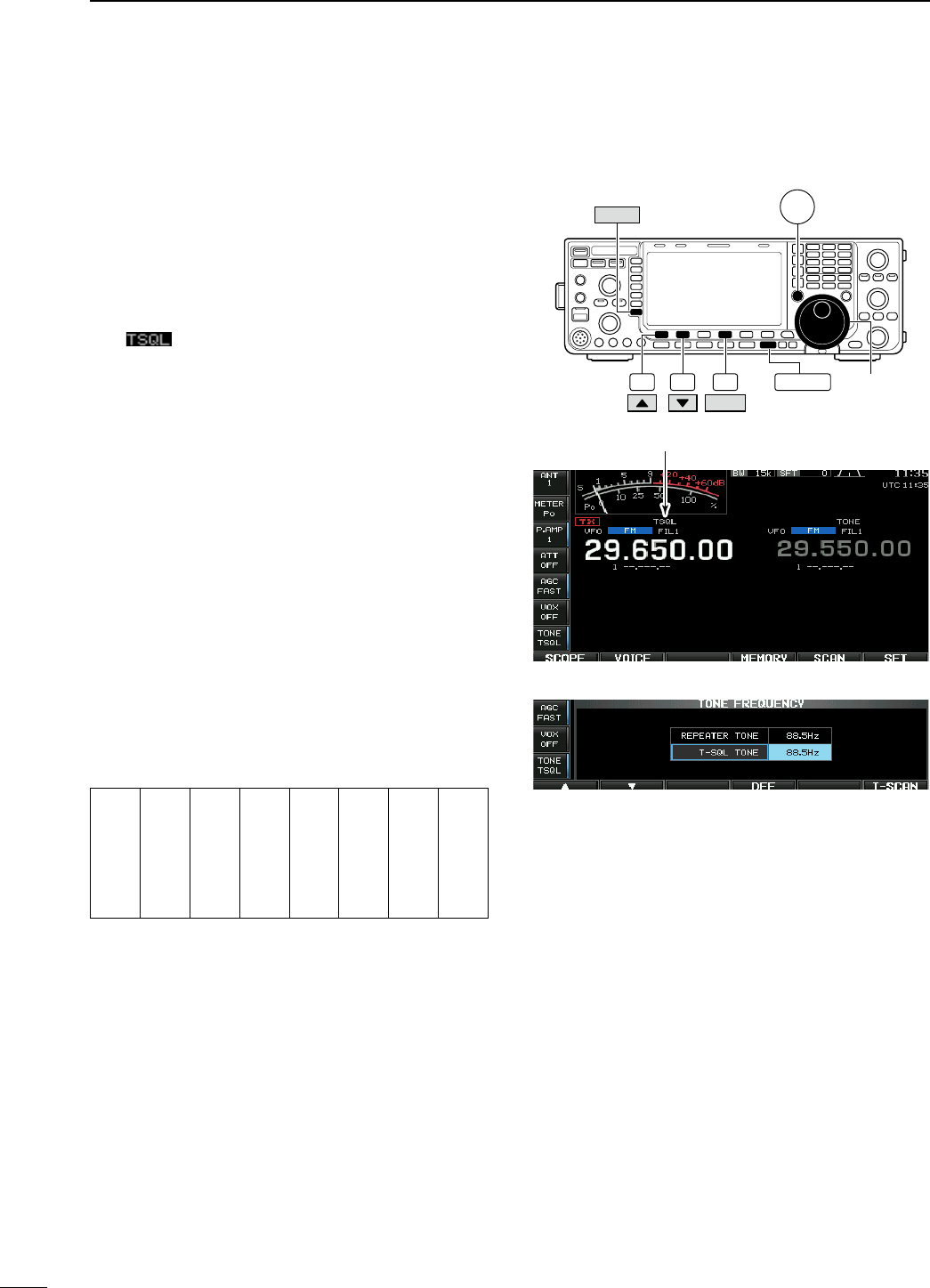
N Tone squelch operation
The tone squelch opens only when receiving a sig-
nal containing a matching subaudible tone. You can
silently wait for calls from group members using the
same tone.
q Set the desired frequency band and select FM
mode.
w Push [TONE] (MF7) to turn the tone squelch func-
tion ON.
• “ ” appears
e Push and hold [TONE] (MF7) for 1 sec. to enter
tone frequency set mode.
r Push [Y] (F-1) or [Z] (F-2) to select T-SQL TONE
item.
t Rotate the main dial to select the desired tone
squelch frequency.
• Push and hold [DEF] (F-4) for 1 sec. to select the
default setting.
y Push [EXIT/SET] to return to the previous indica-
tion.
u When the received signal includes a matching
tone, squelch opens and the signal can be heard.
• When the received signal’s tone does not match,
tone squelch does not open. However, the S-indicator
shows signal strength.
• To open the squelch manually, push [XFC].
i Operate the transceiver in the normal way.
o To cancel the tone squelch, push [TONE] (MF7) to
clear “TSQL.”
• Available tone frequencies (unit: Hz)
67.0
69.3
71.9
74.4
77.0
79.7
82.5
085.4
088.5
091.5
094.8
097.4
100.0
103.5
107.2
110.9
114.8
118.8
123.0
127.3
131.8
136.5
141.3
146.2
151.4
156.7
159.8
162.2
165.5
167.9
171.3
173.8
177.3
179.9
183.5
186.2
189.9
192.8
196.6
199.5
203.5
206.5
210.7
218.1
225.7
229.1
233.6
241.8
250.3
254.1
F-4 EXIT/SET Main dial
F-2F-1
DEF
TONE XFC
Appears
• Tone frequency set mode
63
4RECEIVE AND TRANSMIT
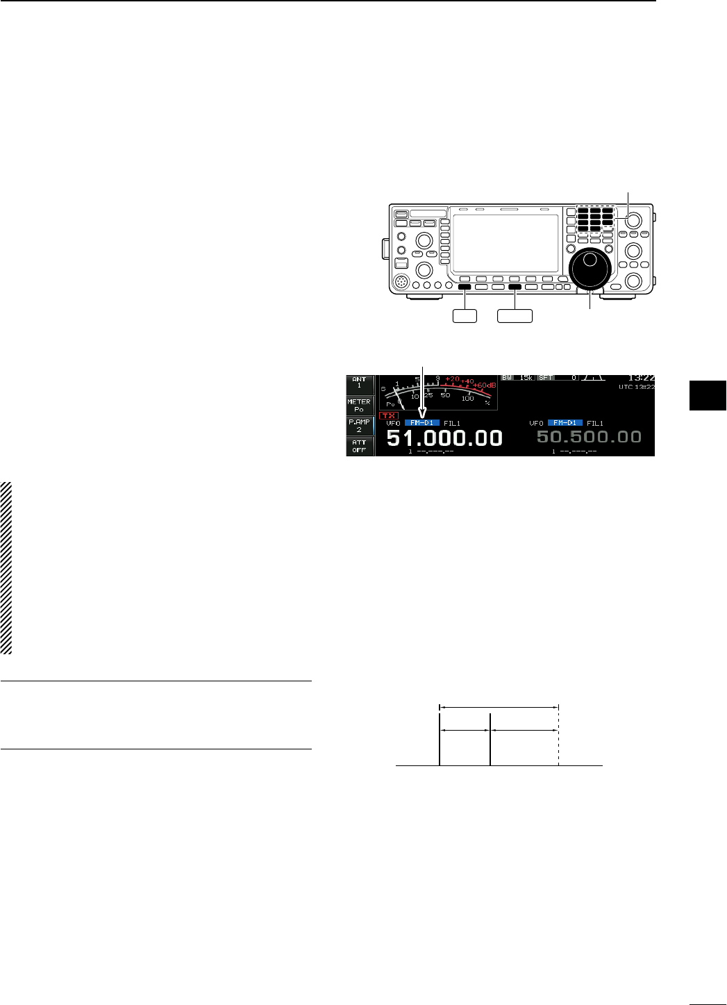
N Data mode (AFSK) operation
When operating AMTOR or PACKET with your TNC
and/or PC software, consult the manual that comes
with the TNC and/or the software.
q Connect a PC and TNC to the transceiver. (p. ??)
w Push a band key to select the desired band.
e Push [SSB] or [AM/FM] to select the desired oper-
ating mode.
r Push and hold [SSB] or [AM/FM] that is pushed in
step e for 1 sec. to turn data mode ON.
• One of “-D1,” “-D2” or “-D3” is additionally appears.
• During data mode selection, push and hold [SSB] or
[AM/FM] for 1 sec. to select data mode 1 (D1), 2 (D2)
and 3 (D3) in sequence.
t Rotate the main dial to tune to the desired signal
and decode it correctly.
• Also use the tuning indicator of the TNC or software.
• During SSB data mode, the 1⁄4 tuning function can be
used for critical tuning.
y Operate the PC (software) or TNC to transmit.
• When operating in SSB data mode, adjust the TNC
output level so that the ALC meter reading doesn’t go
outside the ALC zone.
NOTE: When data mode 1 (D1) is selected, the
audio input from the [ACC1] (pin 4) is used for
transmission instead of [MIC]’s. (Modulation input
connector can be changed in ACC set mode (pgs.
??, ??)
The fixed condition is used for SSB data transmis-
sion as follows:
• [COMP] : OFF
• Tx bandwidth : MID
• Tx Tone (Bass) : 0
• Tx Tone (Trebles) : 0
For your information
Carrier frequency is displayed when SSB data mode
is selected.
See the diagram at right for the tone-pair example.
Main
dial
Band keys
AM/FM
SSB
Appears
• Tone-pair example
200 Hz 2125 Hz
2325 Hz
Carrier frequency
(displayed frequency)
64
4
RECEIVE AND TRANSMIT
1
2
3
4
5
6
7
8
9
10
11
12
13
14
15
16
17
18
19
20
21
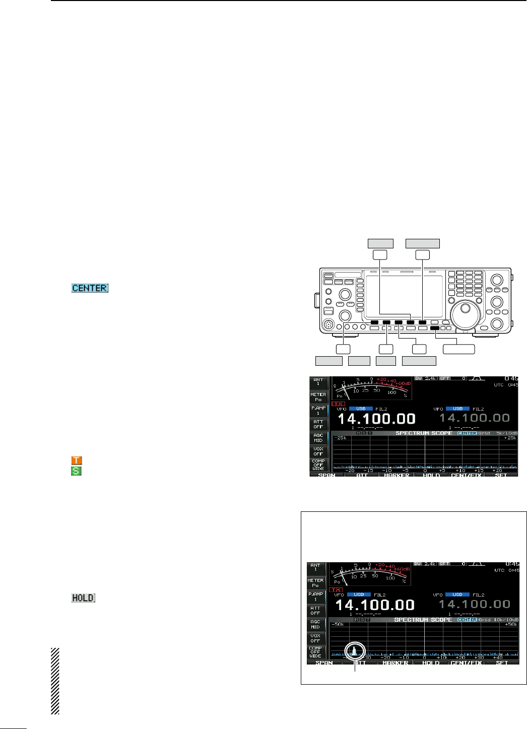
N Spectrum scope screen
This DSP-based spectrum scope allows you to dis-
play the frequency and relative signal strength of
received signals on the strengths of signals. The IC-
7600 has two modes for the spectrum display— one
is center mode, and the other is fixed mode.
In addition, the IC-7600 has a mini scope screen to
save screen space.
D Center mode
Displays signals around the set frequency within the
selected span. The set frequency is always displayed
at the center of the screen.
q Push [EXIT/SET] several times to close a multi-
function screen, if necessary.
w Push [SCOPE] (F-1) to select the scope screen.
e Push [CENT/FIX] (F-5) to select the center mode.
• “ ” is displayed when center mode is selected.
r Push [SPAN] (F-1) several times to select the
scope span.
• ±2.5, ±5.0, ±10, ±25, ±50, ±100 and ±250 kHz are
available.
• Push and hold [SPAN] (F-1) for 1 sec. to return to ±2.5
kHz span.
• Sweep speed is selectable for each span indepen-
dently in scope set mode. (pgs. ??, ??)
t Push [ATT] (F-2) several times to activate an
attenuator or turn the attenuator OFF.
• 10, 20 and 30 dB attenuators are available.
• Push and hold [ATT] (F-2) for 1 sec. to turn OFF the
attenuator.
y Push [MARKER] (F-3) to turn the marker for trans-
mit frequency ON or OFF.
• “ ” displays the marker at the transmit frequency.
• “ ” displays the marker at the sub readout frequency.
• “<<” or “>>” appears when the marker is out of range.
• The spectrum scope shows the transmit signal while
transmitting. This can be deactivated in scope set
mode. (p. ??)
• The spectrum scope shows the peak level hold func-
tion. Peak levels are displayed in the background of the
current spectrum in a different color until the receive
frequency changes. This can be deactivated and the
waveform color can be set in scope set mode. (p. ??)
u Push [HOLD] (F-4) to freeze the current spectrum
display.
• “ ” appears while the function is in use.
• The peak hold function can be deactivated in scope set
mode. (p. ??)
i Push [EXIT/SET] to exit the scope screen.
NOTE: If a strong signal is received, a ghost signal
may also appear. Push [ATT] (F-2) several times to
activate the spectrum scope attenuator in this case.
Spurious signals may be displayed. They are gen-
erated in the internal scope circuit and do not indi-
cate a transceiver malfunction.
F-1 F-2 F-3
F-5
F-4
EXIT/SET
/
SCOPE SPAN AT T MARKER
HOLD CENT/FIX
• Scope spurious signal example
Spurious signals may be received on the spectrum
scope screen regardless of the transceiver’s state
(TX or RX). They are generated in the scope circuit.
This does not indicate a transceiver malfunction.
Scope spurious example
65
4RECEIVE AND TRANSMIT
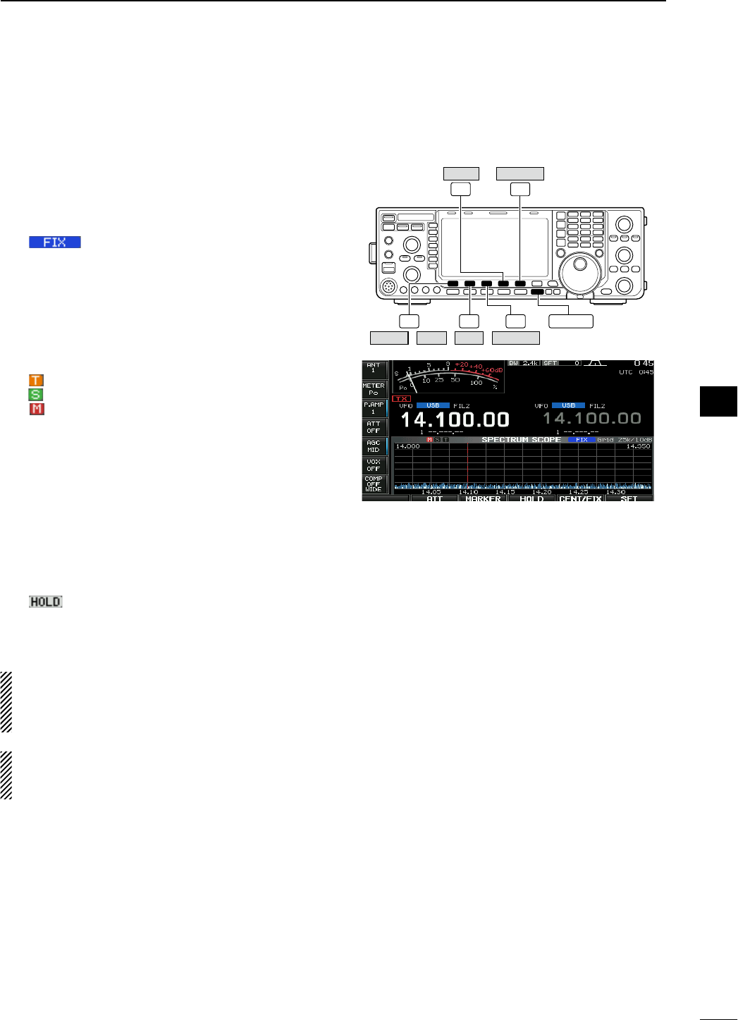
D Fixed mode
Displays signals within the specified frequency range.
Conditions on the selected frequency band can be
observed at a glance when using this mode.
q Push [EXIT/SET] several times to close a multi-
function screen, if necessary.
w Push [SCOPE] (F-1) to select the scope screen.
e Push [CENT/FIX] (F-5) to select the fixed mode.
• “ ” is displayed when fixed mode is selected.
r Push [ATT] (F-2) several times to activate an
attenuator or turn the attenuator OFF.
• 10, 20 and 30 dB attenuators are available.
• Push and hold [ATT] (F-2) for 1 sec. to turn OFF the
attenuator.
t Push [MARKER] (F-3) several times to select the
marker for transmit frequency or turn the marker
OFF.
• “ ” displays the marker at the transmit frequency.
• “ ” displays the marker at the sub readout frequency.
• “ ” displays the marker at the main readout fre-
quency. (always displayed)
• “<<” or “>>” appears when the marker is out of range.
• The spectrum scope shows the transmit signal while
transmitting. This can be deactivated in scope set
mode. (p. ??)
• The spectrum scope shows the peak level hold func-
tion. Peak levels are displayed in the background of the
current spectrum in a different color until the receive
frequency changes. This can be deactivated and the
waveform color can be set in scope set mode. (p. ??)
y Push [HOLD] (F-4) to freeze the current spectrum
waveform.
• “ ” appears while the function is in use.
• The peak hold function can be deactivated in scope set
mode.
u Push [EXIT/SET] to exit the scope screen.
NOTE: If a strong signal is received, a ghost signal
may appear. Push [ATT] (F-2) several times to
activate the spectrum scope attenuator in this
case.
The scope bandwidth can be specified for each fre-
quency band independently in scope set mode.
(pgs. ?? to ??)
F-1 F-2 F-3
F-5
F-4
EXIT/SET
/
SCOPE SPAN AT T MARKER
HOLD CENT/FIX
66
4
RECEIVE AND TRANSMIT
1
2
3
4
5
6
7
8
9
10
11
12
13
14
15
16
17
18
19
20
21
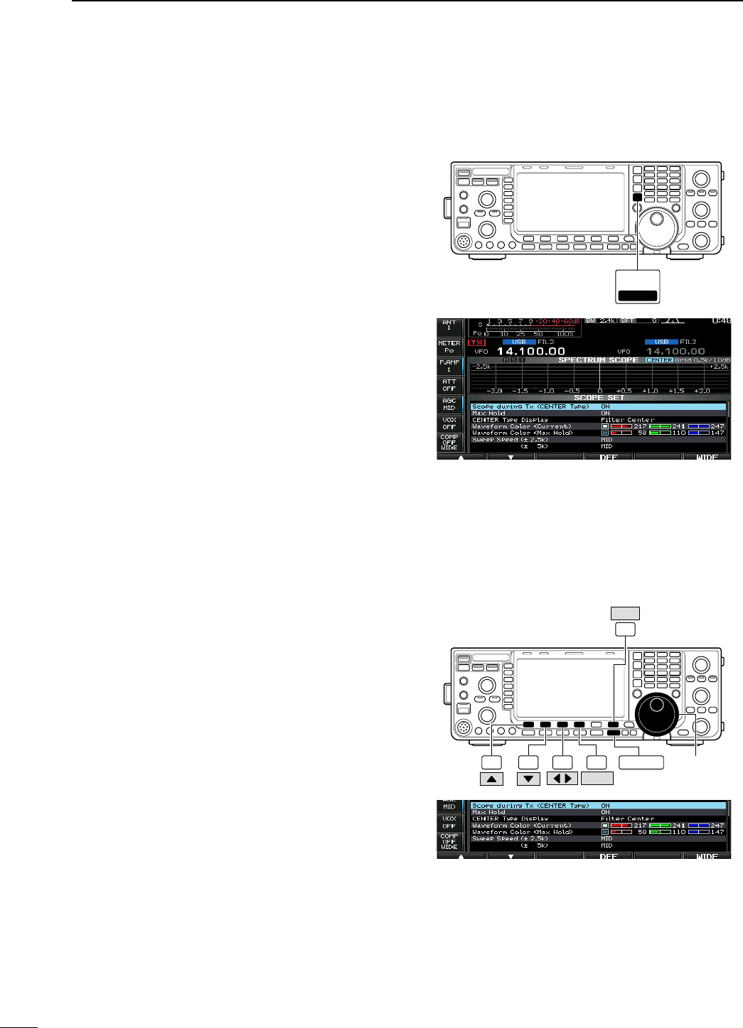
D Mini scope screen indication
The mini scope screen can be displayed with another
screen display, such as set mode menu, decode
screen, memory list screen, etc. simultaneously.
q Set the scope mode (center or fixed), marker,
attenuator, span, etc. in advance. (pgs. ??, ??)
w Push and hold [MAIN/SUB M.SCOPE] for 1 sec. to
select the mini scope indication.
• The S/RF meter type during mini scope indication can
be selected in display set mode (Meter Type (Wide
Screen) item). (p. ??)
D Scope set mode
This set mode is used to set the waveform color,
sweeping speed, scope range for fixed mode, etc.
q During spectrum scope display ON, push
[SET] (F-6) to select scope set mode screen.
• Push [WIDE] (F-6) to toggle the screen size between
normal and wide.
w Push [Y] (F-1) or [Z] (F-2) to select the desired
set item.
e Set the desired condition using the main dial.
• Push and hold [DEF] (F-4) for 1 sec. to select the
default condition or value.
• Push [Ω ≈] (F-3) to select the set contents for some
items.
r Push [EXIT/SET] to exit from set mode.
MAIN
/SUB
M.SCOPE
M.SCOPE
F-1 F-2 F-3 F-4
F-6
EXIT/SET [DIAL]
SET
DEF
67
4RECEIVE AND TRANSMIT
D Scope set mode (continued)
Scope during Tx (CENTER Type) ON
Turn display of the transmit signal ON and OFF.
NOTE: Transmit signal display is available for the
center mode only.
Max Hold ON
Turn the peak level hold function ON and OFF.
CENTER Type Display Filter Center
Select the center frequency of the spectrum scope
indication (center mode only).
• Filter Center : Shows the selected filter’s center
frequency at the center.
• Carrier Point Center
: Shows the selected operating mode
carrier point frequency at the center.
• Carrier Point Center (Abs. Freq.)
: In addition to the carrier point center
setting above, the actual frequency
is displayed for the bottom of the
scope.
Waveform Color (Current)
217 241 247
Set the waveform color for the currently received
signals.
• The color is set in RGB format.
• Push [Ω ≈] (F-3) to select R (Red), G (Green) and
B (Blue), and rotate the ratio from 0 to 255 range.
• The set color is indicated in the box beside the
RGB scale.
Waveform Color (Max Hold)
58 110 147
Set the waveform color for the received signals max-
imum level.
• The color is set in RGB format.
• Push [Ω ≈] (F-3) to select R (Red), G (Green) and
B (Blue), and rotate the ratio from 0 to 255 range.
• The set color is indicated in the box beside the
RGB scale.
Sweep Speed (± 2.5k) MID
Select the sweep speed for the ±2.5 kHz span selec-
tion from SLOW, MID and FAST.
NOTE: Signals may be displayed incorrectly with
“FAST” setting.
(± 5k) MID
Select the sweep speed for the ±5 kHz span selec-
tion from SLOW, MID and FAST.
NOTE: Signals may be displayed incorrectly with
“FAST” setting.
(± 10k) FAST
Select the sweep speed for the ±10 kHz span selec-
tion from SLOW, MID and FAST.
68
4
RECEIVE AND TRANSMIT
1
2
3
4
5
6
7
8
9
10
11
12
13
14
15
16
17
18
19
20
21

D Scope set mode (continued)
(± 25k) FAST
Select the sweep speed for the ±25 kHz span selec-
tion from SLOW, MID and FAST.
(± 50k) FAST
Select the sweep speed for the ±50 kHz span selec-
tion from SLOW, MID and FAST.
(± 100k) FAST
Select the sweep speed for the ±100 kHz span
selection from SLOW, MID and FAST.
(± 250k) FAST
Select the sweep speed for the ±250 kHz span
selection from SLOW, MID and FAST.
Fixed Edges ( 0.03 − 1.60) 0.750 − 1.250 MHz
Set the scope edge frequencies for fixed mode for
bands below 1.6 MHz.
• Set the frequencies within 0.030 to 1.600 MHz
range in 1 kHz steps.
As edge frequencies are set, the other edge fre-
quency will be automatically set for a display band
width of 5 kHz to a maximum of 500 kHz.
( 1.60 − 2.00) 1.800 − 2.000 MHz
Set the scope edge frequencies for fixed mode
scope when the 1.6 to 2 MHz band is selected.
• Set the frequencies within 1.600 to 2.000 MHz
range in 1 kHz steps.
( 2.00 − 6.00) 3.500 − 4.000 MHz
Set the scope edge frequencies for fixed mode
scope when the 2 to 6 MHz band is selected.
• Set the frequencies within 2.000 to 6.000 MHz
range in 1 kHz steps.
As edge frequencies are set, the other edge fre-
quency will be automatically set for a display band
width of 5 kHz to a maximum of 500 kHz.
( 6.00 − 8.00) 7.000 − 7.300 MHz
Set the scope edge frequencies for fixed mode
scope when the 6 to 8 MHz band is selected.
• Set the frequencies within 6.000 to 8.000 MHz
range in 1 kHz steps.
As edge frequencies are set, the other edge fre-
quency will be automatically set for a display band
width of 5 kHz to a maximum of 500 kHz.
69
4RECEIVE AND TRANSMIT

D Scope set mode (continued)
( 8.00 − 11.00) 10.100 − 10.150 MHz
Set the scope edge frequencies for fixed mode
scope when the 8 to 11 MHz band is selected.
• Set the frequencies within 8.000 to 11.000 MHz
range in 1 kHz steps.
As edge frequencies are set, the other edge fre-
quency will be automatically set for a display band
width of 5 kHz to a maximum of 500 kHz.
(11.00 − 15.00) 14.000 − 14.350 MHz
Set the scope edge frequencies for fixed mode
scope when the 11 to 15 MHz band is selected.
• Set the frequencies within 11.000 to 15.000 MHz
range in 1 kHz steps.
As edge frequencies are set, the other edge fre-
quency will be automatically set for a display band
width of 5 kHz to a maximum of 500 kHz.
(15.00 − 20.00) 18.068 − 18.168 MHz
Set the scope edge frequencies for fixed mode
scope when the 15 to 20 MHz band is selected.
• Set the frequencies within 15.000 to 20.000 MHz
range in 1 kHz steps.
As edge frequencies are set, the other edge fre-
quency will be automatically set for a display band
width of 5 kHz to a maximum of 500 kHz.
(20.00 − 22.00) 21.000 − 21.450 MHz
Set the scope edge frequencies for fixed mode
scope when the 20 to 22 MHz band is selected.
• Set the frequencies within 20.000 to 22.000 MHz
range in 1 kHz steps.
As edge frequencies are set, the other edge fre-
quency will be automatically set for a display band
width of 5 kHz to a maximum of 500 kHz.
(22.00 − 26.00) 24.890 − 24.990 MHz
Set the scope edge frequencies for fixed mode
scope when the 22 to 26 MHz band is selected.
• Set the frequencies within 22.000 to 26.000 MHz
range in 1 kHz steps.
As edge frequencies are set, the other edge fre-
quency will be automatically set for a display band
width of 5 kHz to a maximum of 500 kHz.
70
4
RECEIVE AND TRANSMIT
1
2
3
4
5
6
7
8
9
10
11
12
13
14
15
16
17
18
19
20
21

D Scope set mode (continued)
(26.00 − 30.00) 28.000 − 28.500 MHz
Set the scope edge frequencies for fixed mode
scope when the 26 to 30 MHz band is selected.
• Set the frequencies within 26.000 to 30.000 MHz
range in 1 kHz steps.
As edge frequencies are set, the other edge fre-
quency will be automatically set for a display band
width of 5 kHz to a maximum of 500 kHz.
(30.00 − 45.00) 30.000 − 30.500 MHz
Set the scope edge frequencies for fixed mode
scope when the 30 to 45 MHz band is selected.
• Set the frequencies within 30.000 to 45.000 MHz
range in 1 kHz steps.
As edge frequencies are set, the other edge fre-
quency will be automatically set for a display band
width of 5 kHz to a maximum of 500 kHz.
(45.00 − 60.00) 50.000 − 50.500 MHz
Set the scope edge frequencies for fixed mode
scope when the 45 to 60 MHz band is selected.
• Set the frequencies within 45.000 to 60.000 MHz
range in 1 kHz steps.
As edge frequencies are set, the other edge fre-
quency will be automatically set for a display band
width of 5 kHz to a maximum of 500 kHz.
71
4RECEIVE AND TRANSMIT
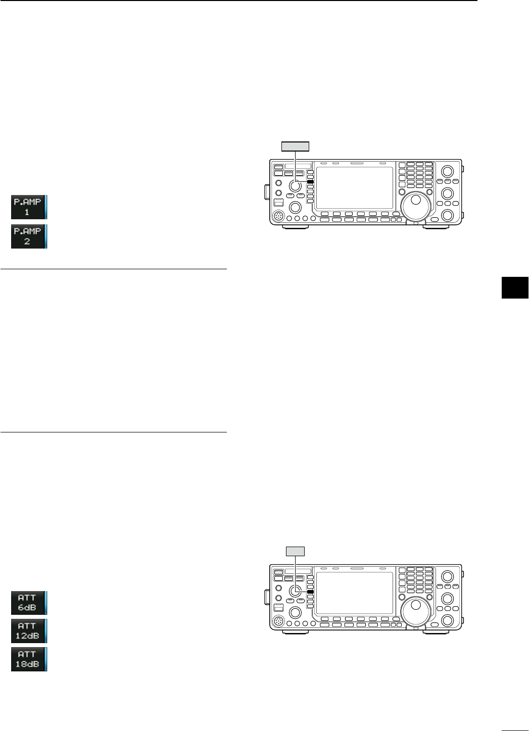
N Preamplifier
The preamp amplifies received signals in the receiver
front end, to improve the S/N ratio and sensitivity. Set
this to preamp 1 or preamp 2 when receiving weak
signals.
± Push [P.AMP] (MF3) several times to set the pre-
amp OFF, preamp 1 ON or preamp 2 ON.
± Push and hold [P.AMP] (MF3) for 1 sec. to turn the
preamp function OFF.
For all HF bands
High-gain preamp for 24 MHz band
and above
About the “P.AMP2”
The “P.AMP 2” is a high gain receive amplifier. When
the “P.AMP 2” is used in the presence of strong elec-
tromagnetic fields, distortion sometimes results. In
such cases, use the transceiver with the “P.AMP 1” or
“P.AMP OFF” setting.
The “P.AMP 2” is most effective when:
• Used on bands above 24 MHz and when signals are
weak.
• Receive sensitivity is insufficient when using low-
gain antennas, or while using a narrow band
antenna (such as small loop, a Beverage antenna
or a short Yagi antenna).
N Attenuator
The attenuator prevents a desired signal from distor-
tion when very strong signals are near the desired
frequency or when very strong electromagnetic fields,
such as from broadcast stations near your location.
± Push [ATT] (MF4) several times to set the attenua-
tor 6 dB, 12 dB, 18 dB or attenuator OFF.
± Push and hold [ATT] (MF4) for 1 sec. to turn the
attenuator function OFF.
6 dB attenuation
12 dB attenuation
18 dB attenuation
P.AMP
ATT
72
4
RECEIVE AND TRANSMIT
1
2
3
4
5
6
7
8
9
10
11
12
13
14
15
16
17
18
19
20
21
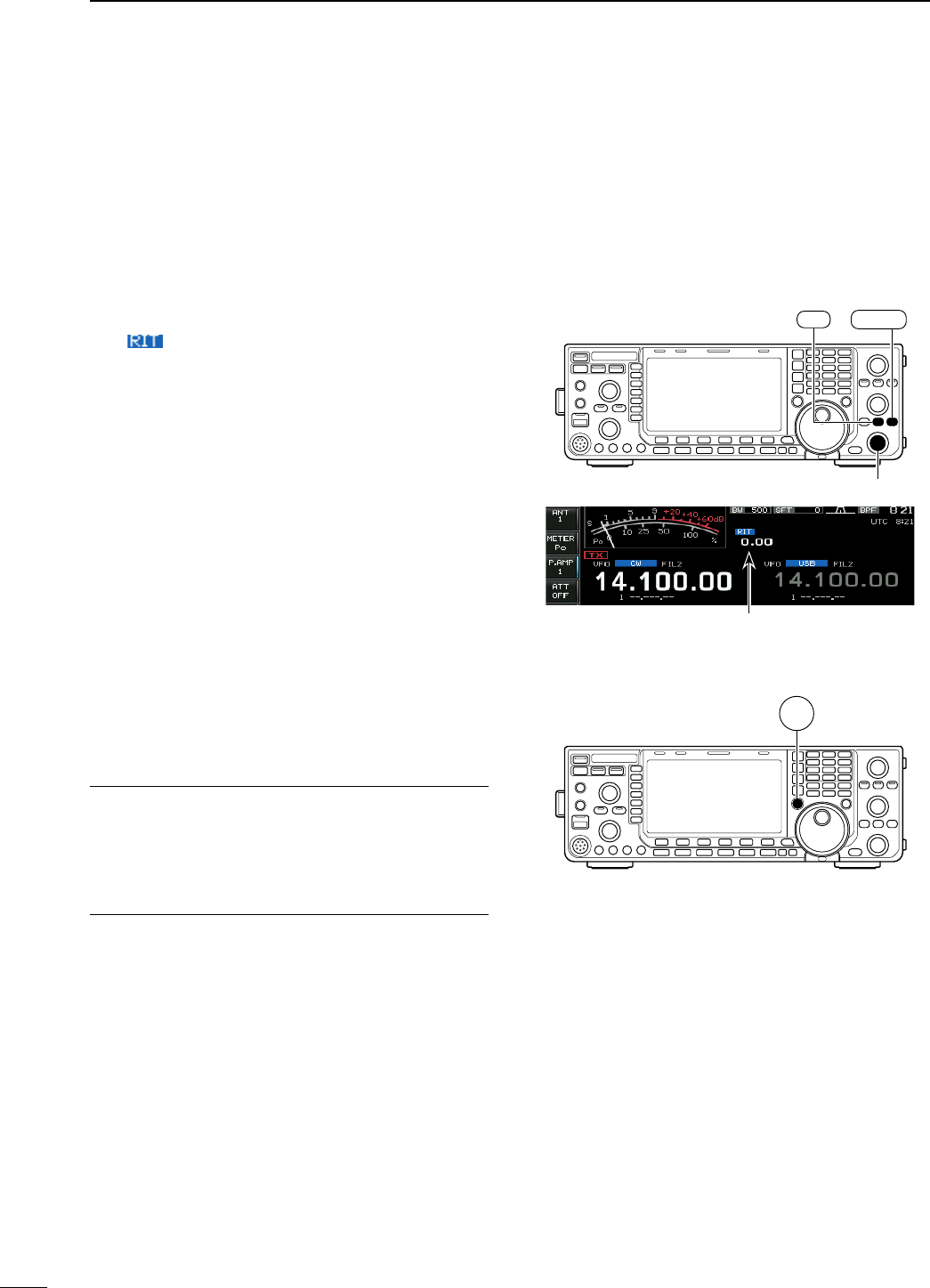
N RIT function
The RIT (Receive Increment Tuning) function com-
pensates for off-frequency operation of the received
station.
The function shifts the receive frequency up to
±9.99 kHz in 10 Hz steps without moving the trans-
mit frequency.
q Push [RIT] to turn the RIT function ON and OFF.
• “ ” and the shifting frequency appear when the
function is ON.
w Rotate the [RIT/∂TX] control.
• Push and hold [CLEAR] for 1 sec. to reset the RIT fre-
quency.
• Push [CLEAR] momentarily to reset the RIT frequency
when the quick RIT/∂TX clear function is ON. (p. ??)
• Push and hold [RIT] for 1 sec. to add the shift fre-
quency to the operating frequency.
D RIT monitor function
When the RIT function is ON, pushing and holding
[XFC] allows you to monitor the operating frequency
directly (RIT is temporarily cancelled).
For your convenience— Calculate function
The shift frequency of the RIT function can be added/
subtracted to the displayed frequency.
± While displaying the RIT shift frequency, push and
hold [RIT] for 1 sec.
[RIT/∂TX]
CLEAR
RIT
XFC
RIT shifting frequency
73
4RECEIVE AND TRANSMIT
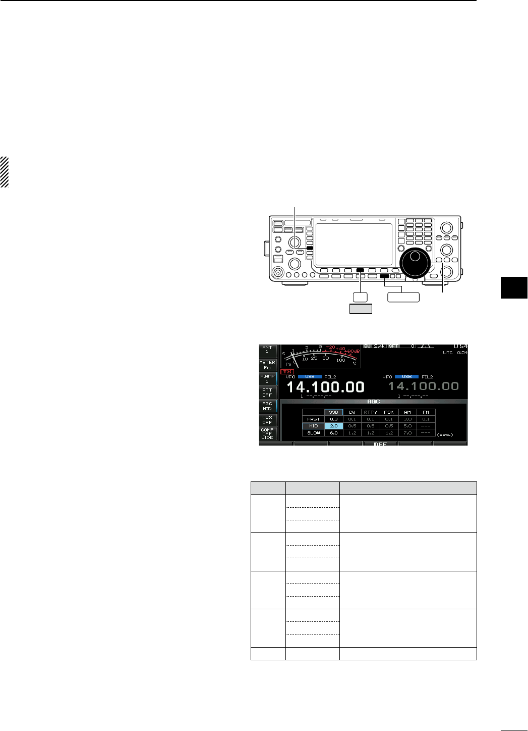
N AGC function
The AGC (auto gain control) controls receiver gain to
produce a constant audio output level even when the
received signal strength varies greatly.
The transceiver has 3 preset AGC characteristics
(time constant: fast, mid, slow) for non-FM mode.
The FM mode AGC time constant is fixed as
‘FAST’ (0.1 sec.) and AGC time constant cannot
be changed.
D Selecting the preset value
q Select any non-FM mode.
w Push [AGC] (MF5) several times to select AGC
fast, AGC medium (MID) or AGC slow.
F-4 EXIT/SET [DIAL]
DEF
[AGC]
D Setting the AGC time constant preset value
q Select any non-FM mode.
w Push and hold [AGC] (MF5) for 1 sec. to enter
AGC set mode.
e Push [AGC] (MF5) several times to select FAST
time constant.
r Rotate the main dial to set the desired time con-
stant for ‘AGC FAST.’
• AGC time constant can be set between 0.1 to 8.0 sec.
(depends on mode) or turned OFF.
• Push and hold [DEF] (F-4) for 1 sec. to select a default
value.
t Push [AGC] (MF5) to select medium time con-
stant.
y Rotate the main dial to set the desired time con-
stant for ‘AGC MID.’
• AGC time constant can be set between 0.1 to 8.0 sec.
(depends on mode) or turned OFF.
• Push and hold [DEF] (F-4) for 1 sec. to select a default
value.
u Push [AGC] (MF5) to select slow time constant.
i Rotate the main dial to set the desired time con-
stant for ‘AGC SLOW.’
• AGC time constant can be set between 0.1 to 8.0 sec.
(depends on mode) or turned OFF.
• Push and hold [DEF] (F-4) for 1 sec. to select a default
value.
o Select another non-FM mode. Repeat steps e to
i if desired.
!0 Push [EXIT/SET] to exit the AGC set mode screen.
• Selectable AGC time constant (unit: sec.)
Mode Default Selectable AGC time constant
SSB
0.3 (FAST) 0.1, 0.2, 0.3, 0.5, 0.8, 1.2, 1.6, 2.0,
2.5, 3.0, 4.0, 5.0, 6.0
2.0 (MID)
6.0 (SLOW)
CW
0.1 (FAST) 0.1, 0.2, 0.3, 0.5, 0.8, 1.2, 1.6, 2.0,
2.5, 3.0, 4.0, 5.0, 6.0
0.5 (MID)
1.2 (SLOW)
RTTY
PSK
0.1 (FAST) 0.1, 0.2, 0.3, 0.5, 0.8, 1.2, 1.6, 2.0,
2.5, 3.0, 4.0, 5.0, 6.0
0.5 (MID)
1.2 (SLOW)
AM
3.0 (FAST) 0.3, 0.5, 0.8, 1.2, 1.6, 2.0, 2.5, 3.0,
4.0, 5.0, 6.0, 7.0, 8.0
5.0 (MID)
7.0 (SLOW)
FM 0.1 (FAST) Fixed
74
4
RECEIVE AND TRANSMIT
1
2
3
4
5
6
7
8
9
10
11
12
13
14
15
16
17
18
19
20
21
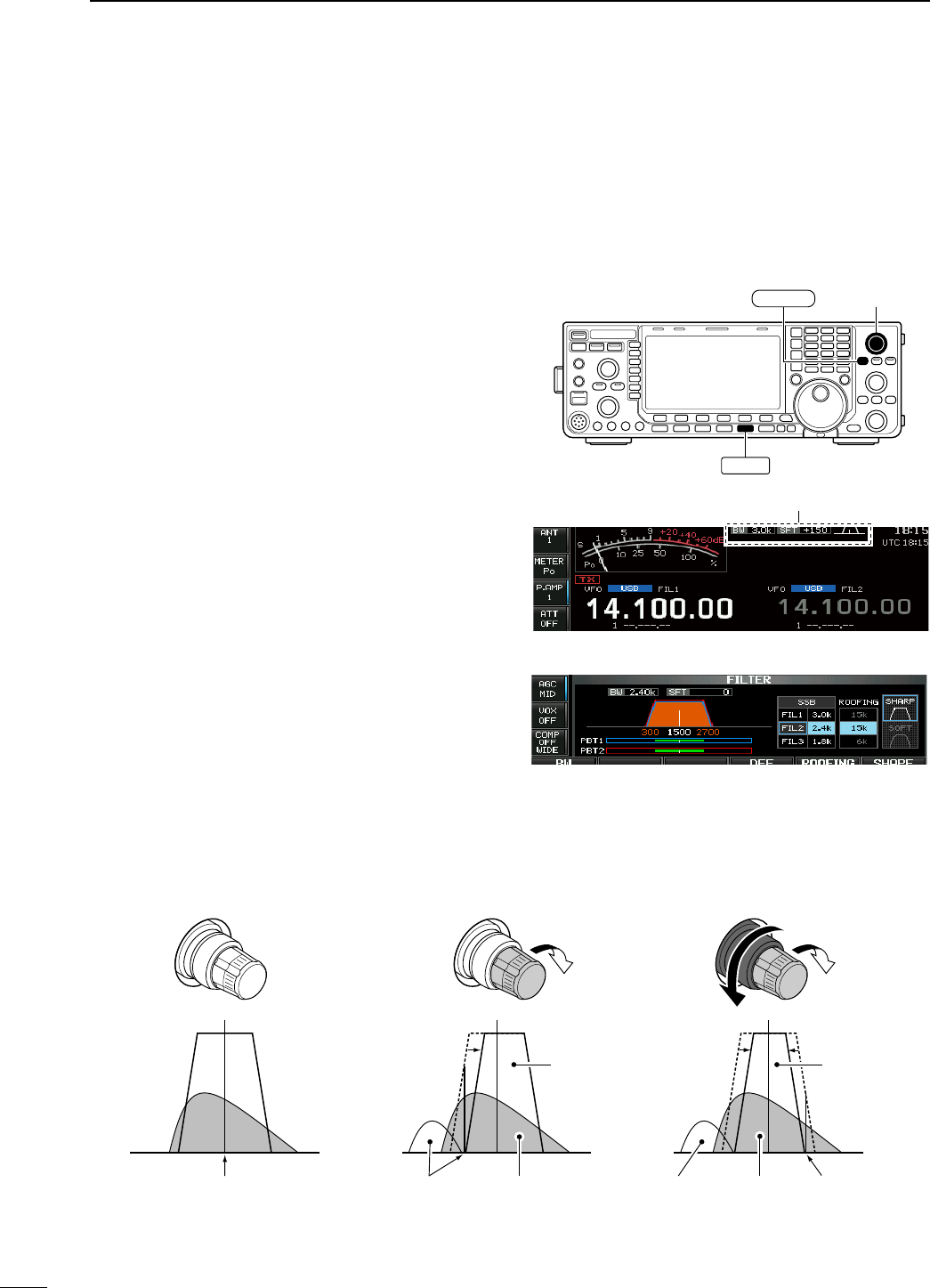
N Twin PBT operation
<MODE> SSB/CW/RTTY/PSK/AM
PBT (Passband Tuning) electronically narrows the IF
passband width by shifting the IF frequency slightly
outside of the IF filter passband to reject interference.
The IC-7600 uses DSP for the PBT function. Moving
both [TWIN-PBT] controls to the same position shifts
the IF both above and below the received frequency.
± The LCD shows the passband width and shift fre-
quency graphically.
• The indicator on the [PBT-CLR] switch lights when
PBT is in use.
± Push and hold [FILTER] for 1 sec. to enter the filter
set screen. Current passband width and shift fre-
quency is displayed in the filter set screen.
± To set the [TWIN-PBT] controls to the center posi-
tions, push and hold [PBT-CLR] for 1 sec.
The variable range depends on the passband width
and mode. The edge of the variable range is half
of the passband width, and PBT is adjustable in 25
(SSB/CW/RTTY/PSK modes) or 100 Hz (AM mode)
steps.
• The [TWIN-PBT] controls should normally be set to
the center positions (PBT setting is cleared) when
there is no interference.
• When PBT is used, the audio tone may be changed.
• Not available for FM mode.
• While rotating the [TWIN-PBT] controls, noise may
occur. This comes from the DSP unit and does not
indicate an equipment malfunction.
• PBT operation example
PBT1
PBT2
PBT1
PBT2
PBT1
PBT2
IF center frequency Interference Desired signal
Passband
Both controls at
center position
Cutting the lower
passband edge
Cutting both lower and
higher passband edges
Interference InterferenceDesired signal
Passband
[TWIN-PBT]
PBT-CLR
FILTER
Shows filter width, shifting value and condition
• Filter set screen
75
4RECEIVE AND TRANSMIT
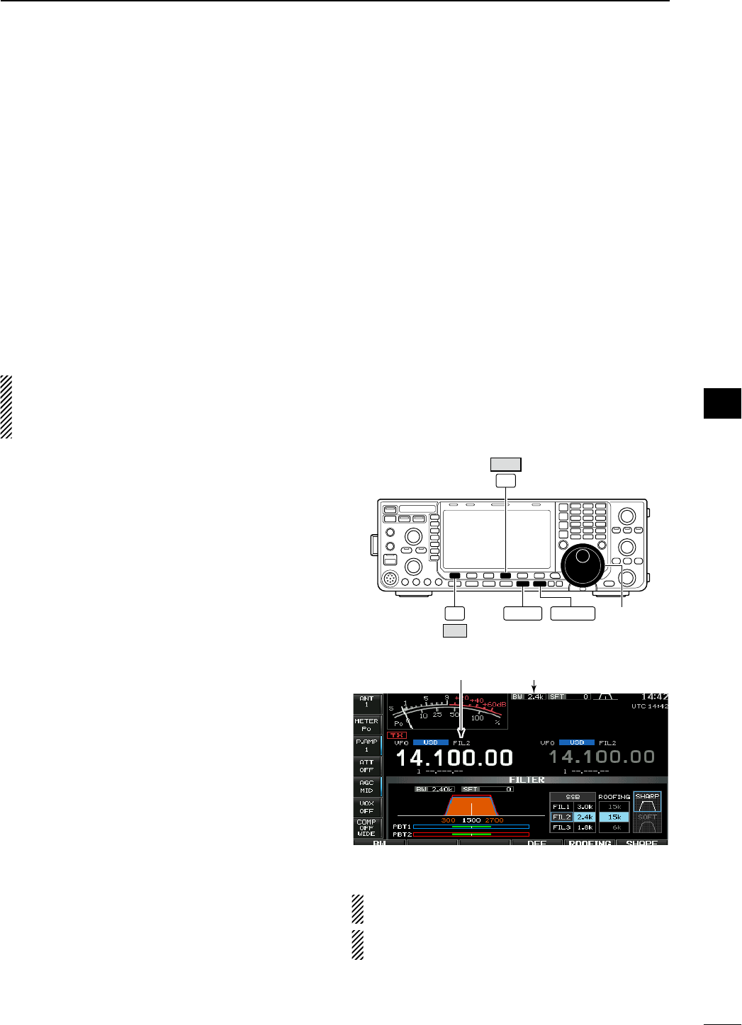
N IF filter selection
The transceiver has 3 passband width IF filters for
each mode.
For SSB, CW and PSK modes, the passband width
can be set within 50 to 3600 Hz in 50 or 100 Hz
steps. A total of 41 passband widths are available.
For RTTY mode, the passband width can be set
within 50 to 2700 Hz in 50 or 100 Hz steps. A total of
32 passband widths are available.
For AM mode, the passband width can be set within
200 Hz to 10 kHz in 200 Hz steps. A total of 50 pass-
band widths are available.
For FM mode, the passband width is fixed and 3
passband widths are available.
The filter selection is automatically memorized in
each mode.
The PBT shift frequencies are automatically mem-
orized in each filter.
D IF filter selection
q Select the desired mode.
w Push [FILTER] several times to select the IF filter
1, 2 or 3.
• The selected passband width and filter number is dis-
played in the LCD.
D Filter passband width setting (except FM
mode)
q Push and hold [FILTER] for 1 sec. to enter filter set
screen.
w Select any mode except FM.
• Passband widths for FM modes are fixed and cannot
be set.
e Push [FILTER] several times to select the desired
IF filter.
r Rotate the main dial after pushing [BW] (F-1) to set
the desired passband width. Then push [BW] (F-1).
• In SSB, CW and PSK modes, the passband width can
be set within the following range.
50 to 500 Hz 50 Hz steps
600 to 3600 Hz 100 Hz steps
• In RTTY mode, the passband width can be set within
the following range.
50 to 500 Hz 50 Hz steps
600 to 2700 Hz 100 Hz steps
• In AM mode, the passband width can be set within the
following range.
200 Hz to 10 kHz 200 Hz steps
• Push and hold [DEF] (F-4) for 1 sec. to select a default
value.
t Repeat steps w to r if desired for other modes.
y Push [EXIT/SET] to exit filter set screen.
FILTER
F-1
BW
F-4
DEF
EXIT/SET Main dial
Selected
IF filter
Passband
width
The PBT shift frequencies are cleared when the
passband width is changed.
This filter set screen graphically displays the
PBT shift frequencies and CW pitch operations.
76
4
RECEIVE AND TRANSMIT
1
2
3
4
5
6
7
8
9
10
11
12
13
14
15
16
17
18
19
20
21
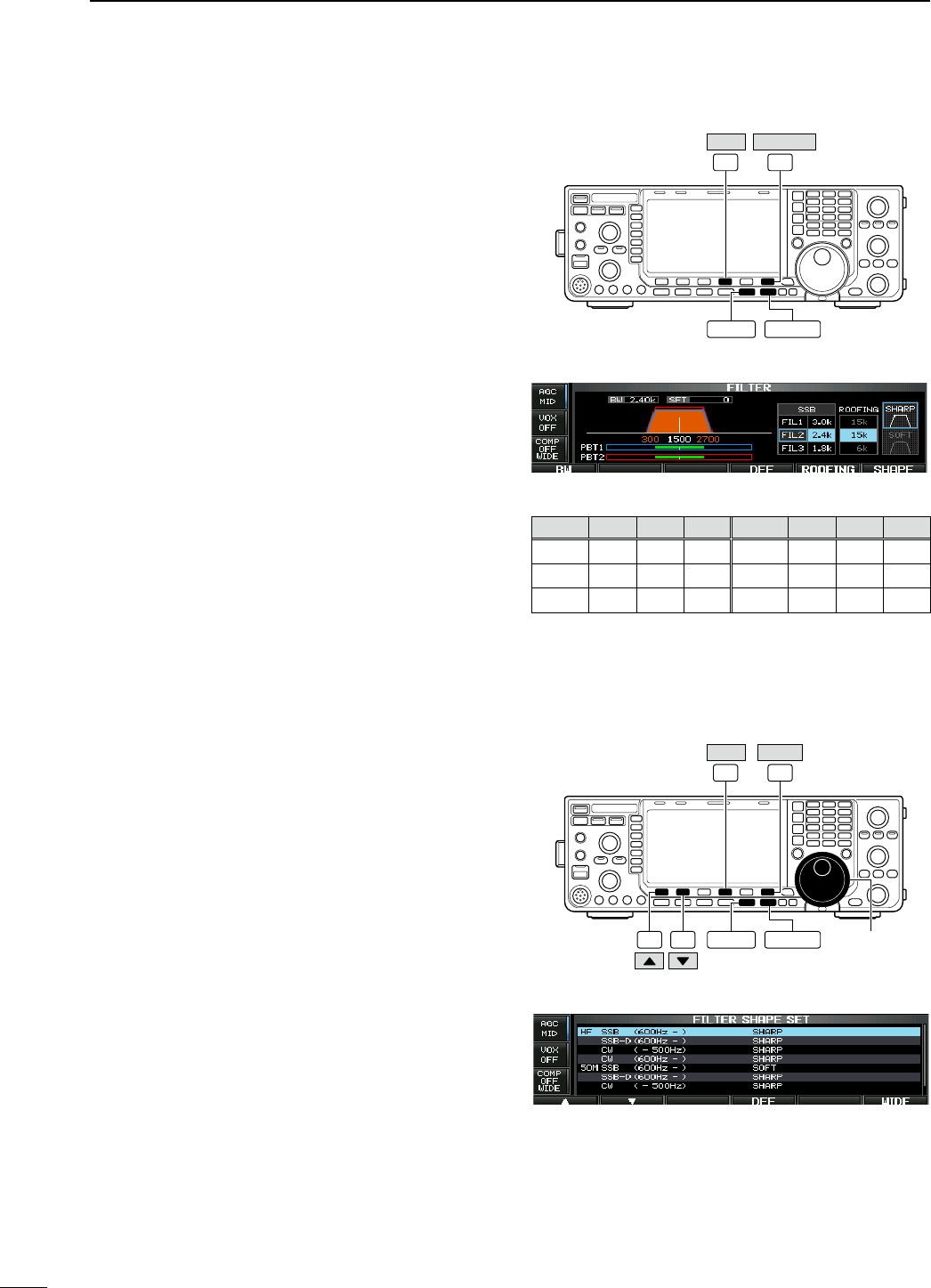
D Roofing filter selection
The IC-7600 has 3, 6 and 15 kHz roofing filters at the
1st IF frequency. The roofing filter provides interfer-
ence reduction from nearby strong signals.
q Push and hold [FILTER] for 1 sec. to enter filter set
screen.
w Select any mode except FM.
e Push [ROOFING] (F-5] to select the desired filter
width from 15 kHz, 6 kHz and 3 kHz.
• Push and hold [DEF] (F-4) for 1 sec. to select a default
value.
r Push [EXIT/SET] to exit filter set screen.
D DSP filter shape
The type of DSP filter shape for each SSB, SSB data
and CW can be selected independently from soft and
sharp.
q Push and hold [FILTER] for 1 sec. to enter filter set
screen.
w Select SSB, SSB data or CW mode.
e Push [SHAPE] (F-6) to select the desired filter
shape from soft and sharp.
r Push [EXIT/SET] to exit filter set screen.
The filter shape can be set for each band (HF and
50 MHz bands), mode, as well as the passband width
setting (CW only) independently from your default
setting in filter shape set mode.
D Filter shape set mode
The type of DSP filter shape for SSB, SSB data and
CW can be selected independently from soft and
sharp.
q Push and hold [FILTER] for 1 sec. to enter filter set
screen.
w Push and hold [SHAPE] (F-6) for 1 sec. to enter fil-
ter shape set mode.
w
Select the desired item using [Y] (F-1) or [Z] (F-2).
e Rotate the main dial to select the filter shape from
soft and sharp.
• Push and hold [DEF] (F-4) for 1 sec. to select a default
value.
t Push [EXIT/SET] to exit filter shape set mode.
F-5F-4
DEF ROOFING
EXIT/SET
FILTER
• Filter set screen
• Default roofing filter (unit: kHz)
Mode FIL1 FIL2 FIL3 Mode FIL1 FIL2 FIL3
SSB 15 15 6 RTTY 15 6 6
SSB-D 666
PSK 666
CW 666
AM 15 15 15
F-1 F-2
F-6F-4
DEF SHAPE
EXIT/SET Main dial
FILTER
• Filter shape set mode
77
4RECEIVE AND TRANSMIT
D Filter shape set mode (continued)
HF SSB (600Hz – ) SHARP
Select the filter shape for SSB mode in HF bands. The set filter shape is automatically used only
when the IF filter is set to 600 Hz or wider.
SSB-D (600Hz – ) SHARP
Select the filter shape for SSB data mode in HF
bands. The set filter shape is automatically used only
when the IF filter is set to 600 Hz or wider.
CW ( – 500Hz) SHARP
Select the filter shape for CW mode in HF bands. The set filter shape is automatically used only
when the IF filter is set to 500 Hz or narrower.
CW (600Hz – ) SHARP
Select the filter shape for CW mode in HF bands. The set filter shape is automatically used only
when the IF filter is set to 600 Hz or wider.
50M SSB (600Hz – ) SOFT
Select the filter shape for SSB mode in 50 MHz
band. The set filter shape is automatically used only
when the IF filter is set to 600 Hz or wider.
SSB-D (600Hz – ) SHARP
Select the filter shape for SSB data mode in 50 MHz
band. The set filter shape is automatically used only
when the IF filter is set to 600 Hz or wider.
CW ( – 500Hz) SHARP
Select the filter shape for CW mode in 50 MHz
band. The set filter shape is automatically used only
when the IF filter is set to 500 Hz or narrower.
CW (600Hz – ) SHARP
Select the filter shape for CW mode in 50 MHz
band. The set filter shape is automatically used only
when the IF filter is set to 600 Hz or wider.
78
4
RECEIVE AND TRANSMIT
1
2
3
4
5
6
7
8
9
10
11
12
13
14
15
16
17
18
19
20
21
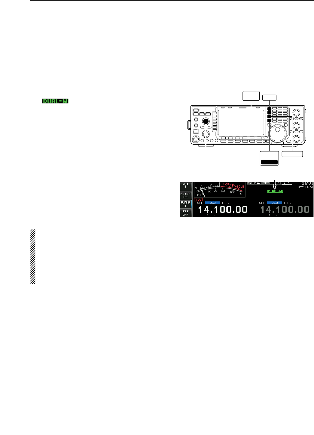
N Dualwatch operation
Dualwatch monitors 2 frequencies simultaneously.
During dualwatch, both frequencies should be on the
same band, because the bandpass filter in the RF cir-
cuit is selected for the main readout frequency.
q Set a desired frequency into the main band.
w Push and hold [DUALWATCH] for 1 sec.
• “ ” appears.
• Equalized receive frequency appears on the sub band
frequency readout. This quick dualwatch function can
be turned OFF in set mode. (p. ??)
• Pushing [DUALWATCH] momentarily activates the
dualwatch with the previously operated frequency.
e Rotate the main dial to set another desired fre-
quency.
r Push [MAIN/SUB M.SCODE] to enables the sub
band access when changing the frequency band,
operating mode, etc. in sub band.
• Push [MAIN/SUB M.SCODE] again for the main band
access.
t Adjust the [BAL] control to set a suitable signal
strength balance between the main and sub read-
out frequencies.
• S-meter shows the combined signal strength.
y To transmit on the sub readout frequency, push
[CHANGE] or [SPLIT].
NOTE:
• A beat note may be heard depending on the fre-
quency combination.
• The RIT function can be used for the main read-
out only.
• The ∂TX function can be used for the transmit
readout (main readout when the split function
OFF; sub readout when the split function ON).
[BAL] control
DUAL
WATCH SPLIT
CHANGE
MAIN
/SUB
M.SCOPE
M.SCOPE
Appears
79
4RECEIVE AND TRANSMIT
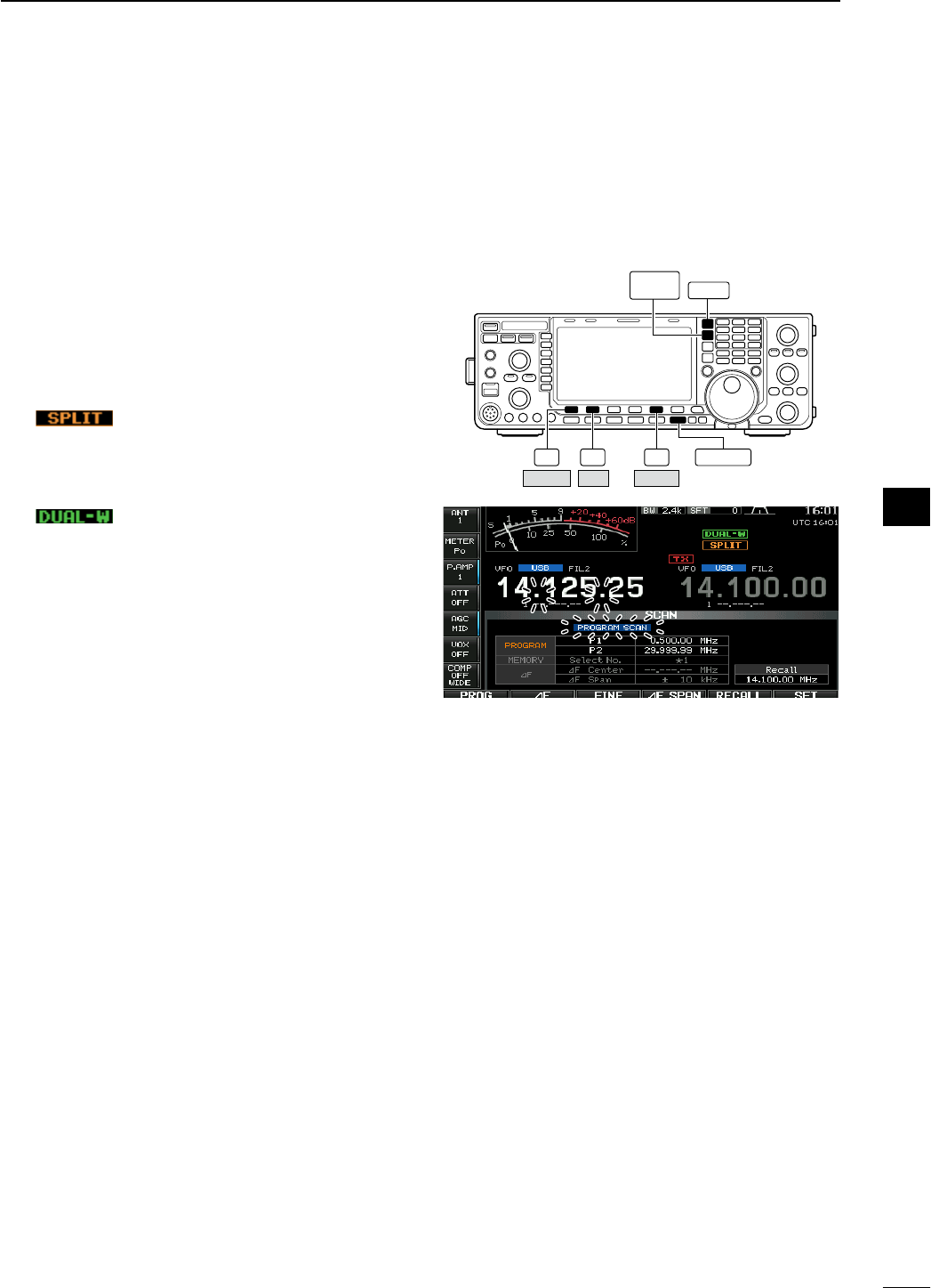
• Scanning during dualwatch
Scanning operates only for the main readout. To
operate the scan during dualwatch, scan on the main
readout and use the sub readout for your QSO using
both dualwatch and split frequency operation.
q Program the desired programmed scan edges in
the same amateur band. See p. ?? for program-
ming.
• If you plan to operate a ∂F scan, programming the
scan edges may not be necessary.
w Push [SPLIT] to turn the split frequency function
ON.
• “ ” appears.
e Select VFO mode for the main readout.
r Set the desired operating frequency for the main
readout.
t Push and hold [DUALWATCH] for 1 sec.
• “ ” appears.
• The main and sub readout frequencies are equalized
and the dualwatch function is turned ON.
y Push [SCAN] (F-5) to select the scan screen.
• Push [EXIT/SET] several times to close a multi-func-
tion screen, if necessary.
u Push [PROG] (F-1) or [∂F] (F-2) to start the pro-
grammed scan or ∂F scan, respectively.
• Scan activates on the main readout between the pro-
grammed scan edges or within the ∂F span.
• Transmitting on the sub readout stops the scan.
i To cancel the scan, push [EXIT/SET].
F-1 F-2 F-5 EXIT/SET
DUAL
WATCH SPLIT
PROG SCAN
∂F
80
4
RECEIVE AND TRANSMIT
1
2
3
4
5
6
7
8
9
10
11
12
13
14
15
16
17
18
19
20
21
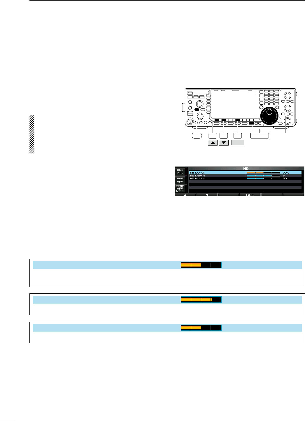
N Noise blanker
<MODE> SSB/CW/RTTY/PSK/AM
The noise blanker eliminates pulse-type noise such
as the noise from car ignitions. The noise blanker is
not available for FM mode.
± Push [NB] to turn the noise blanker function ON
and OFF.
• The indicator on this switch lights green when when the
noise blanker is ON.
When using the noise blanker, received signals
may be distorted if they are excessively strong or
for other types of noise than impulse. Turn the
noise blanker OFF, or set the noise blanker thresh-
old level (see below) to a shallow position in this
case.
D NB set mode
To deal with various type of noise, attenuation level
and noise blanking duration can be set in NB set
mode.
q Push and hold [NB] for 1 sec. to enter NB set
mode.
w
Select the desired item using [Y] (F-1) or [Z] (F-2).
e Rotate the main dial to the desired set value or
condition.
• Push and hold [DEF] (F-4) for 1 sec. to select a default
value.
r Push [EXIT/SET] to exit NB set mode.
F-1 F-2 F-4
DEF
EXIT/SET Main dial
NB
• NB set mode
NB Level
50%
Set the noise blanker threshold level from 0% to
100%.
NB Depth
8
Set the noise attenuation level from 1 to 10.
NB Width
50
Set the blanking duration from 1 to 100.
81
4RECEIVE AND TRANSMIT
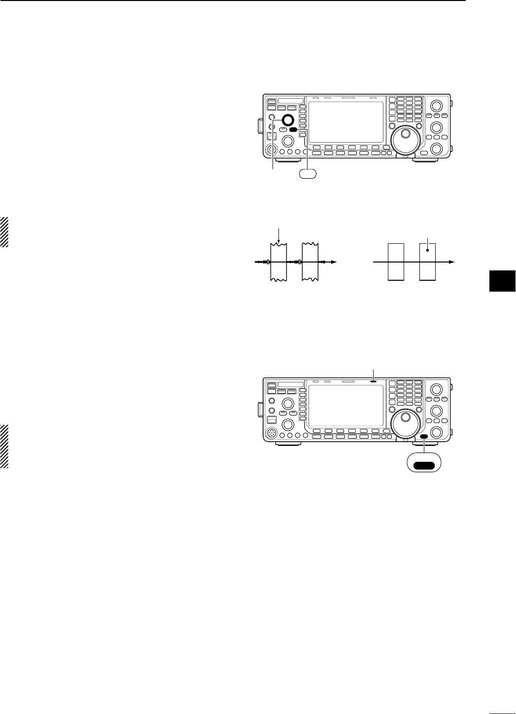
N Noise reduction
The noise reduction function reduces random noise
components and enhances desired signals which are
buried in noise. The DSP performs the random noise
reduction function.
q Push [NR] to turn the noise reduction ON.
• The indicator on this switch lights green.
w Rotate the [NR] control to adjust the noise reduc-
tion level.
e Push [NR] to turn the noise reduction OFF.
• The indicator goes off.
Large rotations of the [NR] control results in audio
signal masking or distortion. Set the [NR] control
for maximum readability.
N Dial lock function
The dial lock function prevents frequency changes
by accidental movement of the tuning dial. The lock
function electronically locks the dial.
± Push and hold [SPEECH/LOCK] for 1 sec. to tog-
gle the dial lock function ON and OFF.
• The [LOCK] indicator lights when the dial lock
function is in use.
NOTE: When “LOCK/SPEECH” is selected in
[[SPEECH/LOCK] Switch] item in others set mode,
pushing [SPEECH/LOCK] activates the dial lock
function. (p. ??)
[NR]
control
NR
Noise reduction OFF Noise reduction activated
Desired
signal (CW)
Noise components
[LOCK] indicator
SPEECH
LOCK
82
4
RECEIVE AND TRANSMIT
1
2
3
4
5
6
7
8
9
10
11
12
13
14
15
16
17
18
19
20
21
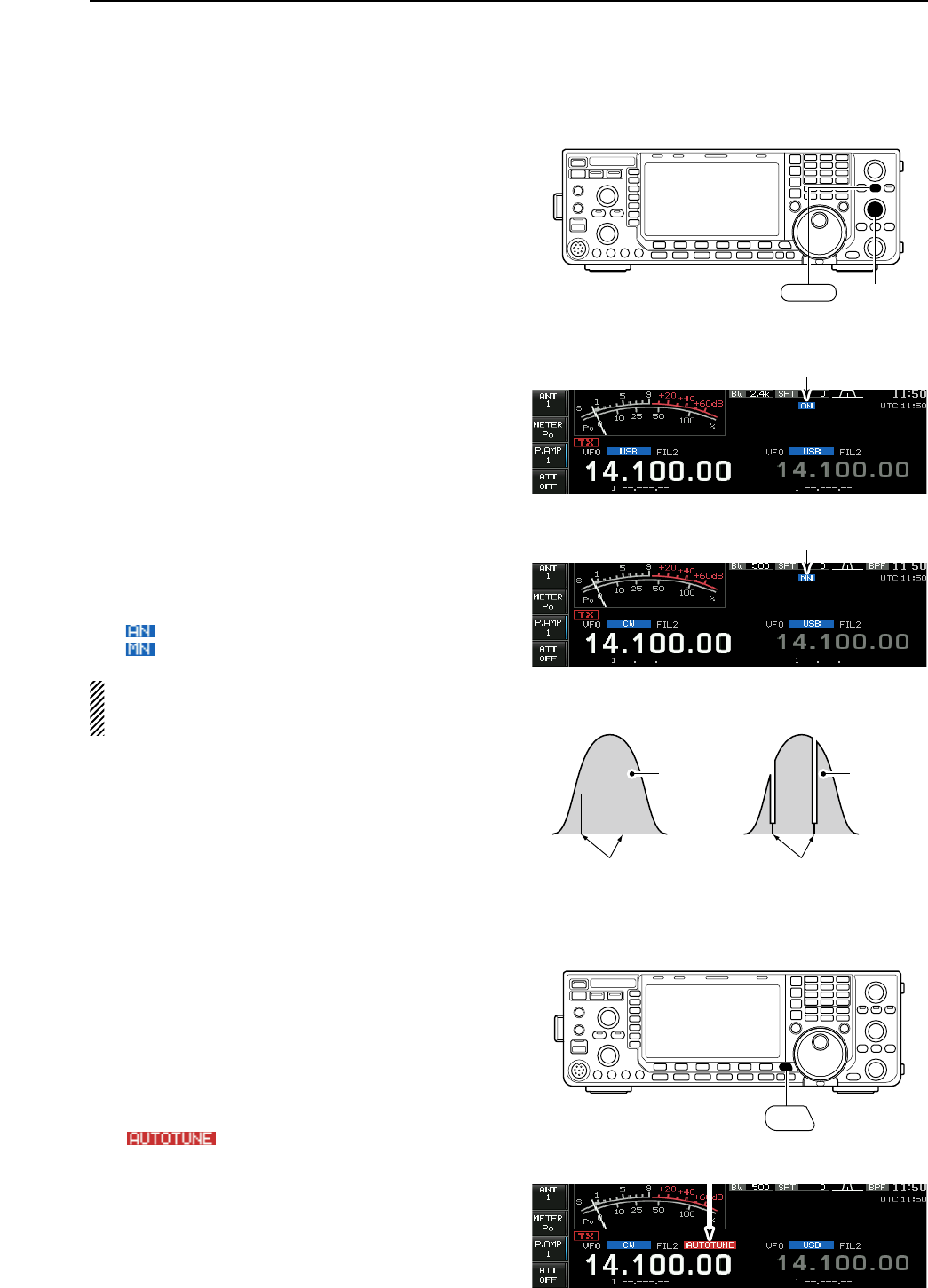
N Notch function
This transceiver has auto and manual notch func-
tions.
The auto notch function uses DSP to automatically
attenuate up to 3 beat tones, tuning signals, etc.,
even if they are moving. The manual notch can be set
to attenuate a frequency via the [NOTCH] control.
The auto notch can be used in SSB, AM and FM
mode.
The manual notch can be used in SSB, CW, RTTY,
PSK and AM modes.
± Push [NOTCH] to toggle the notch function
between auto, manual and OFF in SSB and AM
modes.
± Push [NOTCH] to turn the manual notch function
ON and OFF in CW, RTTY, PSK modes.
± Push [NOTCH] to turn the auto notch function ON
and OFF in FM mode.
• The indicator on this switch lights green.
• When the manual notch function is ON, push and hold
[NOTCH] for 1 sec. to select the notch filter width for
manual notch from wide, middle and narrow.
• Set to attenuate a frequency for manual notch via the
[NOTCH] control.
• “ ” appears when auto notch is in use.
• “ ” appears when manual notch is in use.
While tuning the manual notch, noise may be
heard. This comes from the DSP unit and does not
indicate an equipment malfunction.
N Autotune function
<MODE> CW/AM
The Automatic tuning function tunes the displayed fre-
quency (max. CW: 500 Hz, AM: ±5 kHz) automatically
when an off-frequency signal is received. This func-
tion is active while in CW or AM mode is selected.
± Push [AUTOTUNE] to toggle the autotune function
ON or OFF.
• “ ” blinks when autotune function is acti-
vated.
• After 30 sec. has passed, the autotune function stops
tuning automatically even it’s still off-frequency.
[NOTCH]
control
NOTCH
• Auto notch indication
Appears
• Manual notch indication
Appears
Unwanted tone
frequency
Desired
signal (AF)
Desired
signal (AF)
Particular frequency
is attenuated
Auto notch OFF Auto notch ON
AUTO
TUNE
Appears
83
4RECEIVE AND TRANSMIT