ICOM orporated 307300 HF/50 MHz TRANSCEIVER User Manual IC 718 Instruction Manual
ICOM Incorporated HF/50 MHz TRANSCEIVER IC 718 Instruction Manual
UserManual.wiki
>
ICOM orporated
>
307300 User Manual
>
User Manual 2
Contents
1.
User Manual 1
2.
User Manual 2
User Manual 2
Navigation menu
Upload a User Manual
Namespaces
Wiki Guide
HTML
PDF
Info
Views
User Manual
Discussion / Help
Navigation
![N VOX function<MODE> SSB/AM/FMThe VOX (Voice-Operated Transmission) function switches between transmit and receive with your voice. This function provides “hands-free” operation.D Using the VOX functionq Select a phone mode (SSB, AM, FM).w Push [VOX] (MF6) to turn the VOX function ON or OFF. • “VOX” appears while the VOX is in use.D Adjusting the VOX functionq Select a phone mode (SSB, AM, FM).w Push and hold [VOX] (MF6) for 1 sec. to enter VOX set mode.e Select the desired item using [Y] (F-1) or [Z] (F-2).r Rotate the main dial to the desired set value or condition. • Push and hold [DEF] (F-4) for 1 sec. to select a default value.t Push [EXIT/SET] to exit VOX set mode.F-1 F-2 F-4DEFEXIT/SET Main dial[VOX]SSB AM/FM• VOX set mode screenVOX Gain50%This item adjusts the VOX gain for the VOX func-tion. Higher values make the VOX function more sensitive to your voice.While speaking into the microphone with your nor-mal voice level, rotate the main dial to the point where the transceiver is continuously transmitting.This setting can be adjusted from 0% to 100% in 1%steps.Anti–VOX50%This item adjusts the ANTI-VOX gain for the VOX function. Higher values make the VOX function less sensitive to receiver output audio from a speaker or headphones.During receive, rotate the main dial to the point where the transceiver does not switch to transmit due to received audio from the speaker.This setting can be adjusted from 0% to 100% in 1%steps.VOX Delay0.2sSet the VOX delay for a convenient interval before returning to receive within 0.0 to 2.0 sec. range. VOX Voice Delay OFFSet the VOX voice delay to prevent clipping of the first few syllables of a transmission when switching to transmit.OFF, Short, Mid and Long settings are available. When using the VOX voice delay, turn the TX monitor function OFF to prevent transmitted audio from be echoed.844RECEIVE AND TRANSMIT123456789101112131415161718192021](https://usermanual.wiki/ICOM-orporated/307300.User-Manual-2/User-Guide-1066301-Page-1.png)
![N Break-in function<MODE> CWThe break-in function is used in CW mode to auto-matically toggle the transceiver between transmit and receive when keying. The IC-7600 is capable of full break-in or semi break-in.D Semi break-in operationDuring semi break-in operation, the transceiver imme-diately transmits when keying, then returns to receive after a pre-set delay time has passed from when you stop keying.q Push [CW] to select CW or CW-R mode.w Push [BK-IN] (MF6) once or twice to turn the semi break-in function ON. • “BKIN” appears.e Rotate [BK-IN DELAY] to set the break-in delay time (the delay from transmit to receive).When using a paddle, rotate [KEY SPEED] to adjust the keying speed.D Full break-in operationDuring full break-in operation, the transceiver imme-diately transmits when keying, then returns to receive after you stop keying.q Push [CW] to select CW or CW-R mode.w Push [BK-IN] (MF6) once or twice to turn the full break-in function ON. • “F-BKIN” appears.When using a paddle, rotate [KEY SPEED] to adjust the keying speed.[BK-IN DELAY] [KEY SPEED][BK-IN] CW[KEY SPEED][BK-IN] CWAppearsAppears854RECEIVE AND TRANSMIT](https://usermanual.wiki/ICOM-orporated/307300.User-Manual-2/User-Guide-1066301-Page-2.png)
![N Speech compressor<MODE> SSBThe speech compressor increases average RF output power, improving signal strength and readability.q Push [SSB] to select USB or LSB mode.w Push and hold [COMP] (MF7) for 1 sec. to select COMP TBW set screen.e Adjust the [MIC GAIN] control so that the ALC meter reads within the ALC zone, whether or not you speak softly or loudly.t Push [COMP] to turn the speech compressor ON.r While speaking into the microphone, rotate the main dial , so that the COMP meter reads within the COMP zone (10 to 20 dB range) for your nor-mal voice level. When the COMP meter peaks exceed 20 dB, your transmitted voice may be distorted.t Push [COMP] (MF7) or [EXIT/SET] to exit COMP TBW set mode.y Adjust the ALC meter reading within the 30 to 50% range of the ALC scale. (p. ??)N Transmit filter width setting<MODE> SSBThe transmit filter width for SSB mode can be selected from wide, middle and narrow.q Push [SSB] to select USB or LSB mode.w Push and hold [COMP] (MF7) for 1 sec. to select COMP TBW set screen.t Push [COMP] to turn the speech compressor ON or OFF.t Push [TBW] (F-3) several times to select the desired transmit filter width from wide, middle and narrow. • The filter can be independently set on the speech com-pressor function is ON and OFF. • The following filters are specified as the default. Each of the filter width can be re-set in level set mode. (p. ??) WIDE : 100 Hz to 2.9 kHz MID : 300 Hz to 2.7 kHz NAR : 500 Hz to 2.5 kHzt Push [COMP] (MF7) or [EXIT/SET] to exit COMP TBW set mode.[MIC GAIN][COMP]EXIT/SET Main dialSSB• COMP/TBW set screen[COMP]EXIT/SETF-3TBWSSBSpeech compressor is ONSpeech compressor is OFF“WIDE” setting864RECEIVE AND TRANSMIT123456789101112131415161718192021](https://usermanual.wiki/ICOM-orporated/307300.User-Manual-2/User-Guide-1066301-Page-3.png)
![N ∂TX functionThe ∂TX function shifts the transmit frequency up to ±9.999 kHz in 1 Hz steps (10 Hz steps when cancel-ling the 1 Hz step readout) without moving the receive frequency.q Push [∂TX] to turn ∂TX function ON. • “ ” and the shifting frequency appear when the function is ON.w Rotate the [RIT/∂TX] control.e To reset the ∂TX frequency, push and hold [CLEAR] for 1 sec. • Push [CLEAR] momentarily to reset the ∂TX fre-quency when the quick RIT/∂TX clear function is ON. (p. ??)r To cancel the ∂TX function, push [∂TX] again. • “ ” and the shifting frequency disappears.When RIT and ∂TX are ON at the same time, the [RIT/∂TX] control shifts both the transmit and receive frequencies from the displayed frequency at the same time.D ∂TX monitor functionWhen the ∂TX function is ON, pushing and holding [XFC] allows you to monitor the operating frequency directly (∂TX is temporarily cancelled). For your convenience— Calculate functionThe shift frequency of the ∂TX function can be added/subtracted to the displayed frequency.± While displaying the ∂TX shift frequency, push and hold [∂TX] for 1 sec.N Monitor functionThe monitor function allows you to monitor your trans-mit IF signals in any mode. Use this to check voice characteristics while adjusting SSB transmit parame-ter (p. ??).The CW side tone functions regardless of the [MONITOR] switch setting.q Push [MONITOR] to switch the monitor function ON and OFF. • The indicator on this switch lights green when the mon-itor function is ON.w Push and hold [MONITOR] to monitor set mode.e Rotate the main dial to adjust the monitor level. • Push and hold [DEF] (F-4) for 1 sec. to select a default value.r Push [EXIT/SET] to exit monitor set mode.NOTE: When using the VOX voice delay, turn the monitor function OFF; or transmitted audio will be echoed.[RIT/∂TX]∂TX CLEARXFCEXIT/SET Main dialF-4DEFMONITOR• Monitor set modeAppears874RECEIVE AND TRANSMIT](https://usermanual.wiki/ICOM-orporated/307300.User-Manual-2/User-Guide-1066301-Page-4.png)
![N Split frequency operationSplit frequency operation allows you to transmit and receive in the same mode on two different frequen-cies. Split frequency operation is performed using 2 frequencies on the main and sub readouts.The following is an example of setting 21.290 MHz for receiving and 21.310 MHz for transmitting.q Set 21.290 MHz (USB) in VFO mode.w Push [SPLIT] momentarily, then push and hold [CHANGE] for 1 sec. • The quick split function is much more convenient for selecting the transmit frequency. See the next section for details. • The equalized transmit frequency and “ ” appear on the LCD. • [SPLIT] indicator lights. • “ ” appears to show the transmit frequency read-out.e Rotate the main dial while pushing [XFC] to set the transmit frequency to 21.310 MHz. • The transmit frequency can be monitored while push-ing [XFC].r Now you can receive on 21.290 MHz and transmit on 21.310 MHz.To change the transmit and receive frequencies, push [CHANGE] to exchange the main and sub readouts. CONVENIENT• Direct shift frequency inputThe shift frequency can be entered directly.q Push [F-INP ENT].w Enter the desired shift frequency with the digit keys. • 1 kHz to 1 MHz can be set. • When you require a negative shift direction, push in advance.e Push [SPLIT] to input the shift frequency in the sub readout and the split function is turned ON.• Dualwatch functionThe dualwatch function is convenient for tuning the transmit frequency while monitoring both frequencies used for transmitting and receiving.• Split lock function (p. ??)Accidentally releasing [XFC] while rotating the main dial changes the receive frequency. To prevent this, use both the split lock and dial lock functions to change the transmit frequency only. The split lock function cancels the dial lock function while pushing [XFC] during split frequency operation.The dial lock’s effect during split frequency operation can be selected in the set mode for both receive and transmit frequencies; or only the receive frequency. (p. ??)Main dial[SPLIT] indicator SPLITMAIN/SUBM.SCOPEM.SCOPEXFCCHANGE• When the split function ON• When [XFC] is pushed• The split frequency operation is ready884RECEIVE AND TRANSMIT123456789101112131415161718192021](https://usermanual.wiki/ICOM-orporated/307300.User-Manual-2/User-Guide-1066301-Page-5.png)
![N Quick split functionWhen you find a DX station, an important consider-ation is how to set the split frequency.When you push and hold the [SPLIT] switch for 1 sec., the split frequency operation is turned ON, and the sub readout frequency is equalized to the main readout frequency, then enters standby for transmit frequency input.This shortens the time needed to begin split fre-quency operation.The quick split function is ON by default. For your convenience, it can be turned OFF in others set mode. (p. ??) In this case, the [SPLIT] switch does not equalize the main and sub readout frequencies.q Suppose you are operating at 21.290 MHz (USB) in VFO mode. w Push and hold [SPLIT] for 1 sec. • Split frequency operation is turned ON. • The sub readout is equalized to the main readout fre-quency. • The sub readout enters standby for transmit frequency input and “ ” appears. • During FM mode operation, the sub readout frequency shifts from the main readout frequency according to the others set mode setting.e Rotate the main dial to set the transmit frequency; or, input the transmit frequency using the keypad and [F-INP ENT]; or, input a shift frequency using the keypad and [SPLIT]. • “ ” disappears when [F-INP ENT] is pushed. • Offset frequency setting with the keypad and [SPLIT]. [Example] To transmit on 1 kHz higher frequency: - Push [1.8 1] then [SPLIT]. To transmit on 3 kHz lower frequency: - Push [GENE •], [7 3] then [SPLIT].D Split lock functionThe split lock function is convenient for changing only the transmit frequency. When the split lock function is not used, accidentally releasing [XFC] while rotat-ing the main dial, changes the receive frequency. The split lock function is ON by default, but can be turned OFF in set mode. (p. ??)q While split frequency operation is ON, push and hold [SPEECH/LOCK] for 1 sec. to activate the split lock function. • [LOCK] indicator lights.w While pushing and holding [XFC], rotate the main dial to change the transmit frequency. • If you accidentally release [XFC] while rotating the main dial, the receive frequency does NOT change.Main dial[SPLIT] indicator KeypadXFCSPLITMain dial[LOCK] indicatorSPEECHLOCKXFC894RECEIVE AND TRANSMIT](https://usermanual.wiki/ICOM-orporated/307300.User-Manual-2/User-Guide-1066301-Page-6.png)
![N About digital voice recorderThe IC-7600 has digital voice memories, up to 4 messages for transmit, and up to 20 messages for receive.A maximum message length of 30 sec. can be recorded into receive memory (total message length for all channels of up to 209 sec.) and a total mes-sage length of up to 99 sec. can be recorded in trans-mit memory.The transmit memory is very convenient for repeated CQ and exchange transmissions in contests, as well as when making repeated calls to DX’peditions.q Select any mode.w Push [VOICE] (F-2) to display voice recorder screen.e Push [EXIT/SET] to display voice recorder menu.r Push [PLAY] (F-1) or [MIC REC] (F-2) to select the desired memory channel screen, then record audio or playback the contents as described below.t Push [EXIT/SET] twice to exit voice recorder screen.F-2F-1 EXIT/SET PLAYREC• Example— When [REC] is pushed and held for 1sec.• Example— When [REC] is pushed momentarily• Playing back the all contents in a channel • Playing back the end of 5 sec.* in a channel20 sec.15 sec.(default)30 sec. (max.) Not playing back Play back (5 sec.; default)3 sec.30 sec.Push REC momentarily within 30 sec. after pushing and holding REC for 1 sec., records the all contents.Push REC momentarily records the contents of the previous 15 sec.*When REC is pushed momentarily again within 15 sec.* from the last REC operation, all the contents between REC operations will be recorded.Push REC momentarily after passing 30 sec. from pushing and holding REC for 1 sec., records the 30 sec. before canceling the record.These contents won’t be recorded.*The playing back time period can be changed with “Short Play Time” in voice set mode (p. ??).NOTE: The contents will be recorded into an independent memory channels automatically.Push and hold REC for 1 sec.(starts recording)Push REC momentarily(starts recording)Push REC momentarily(starts recording)Push REC momentarily(stops recording)Push and hold REC for 1 sec.(starts recording)Push REC momentarily(stops recording)Push PLAY (F-3) momentarily.Or, push and hold PLAY for 1 sec. Push PLAY momentarily.*The recording time period can be changed with “Normal Rec Time” in voice set mode (p. ??).590VOICE RECORDER FUNCTIONS123456789101112131415161718192021](https://usermanual.wiki/ICOM-orporated/307300.User-Manual-2/User-Guide-1066301-Page-7.png)
![N Recording a received audioUp to 20 receive voice memories are available in the IC-7600. A total of 209 sec. of audio can be recorded in receive messages. However, the maximum record-able length into a single message is 30 sec.This voice recorder records not only the received audio, but also the information such as set operat-ing frequency, mode, and the recording time for your future reference.D Basic recordingq Push [EXIT/SET] several times to close a multi-function screen, if necessary.w Select the desired mode.e Push [VOICE] (F-2) to call up the voice recorder screen. • Previously selected screen, TX or RX memory, is dis-played. If the TX memory channel (T1–T4) appears, push [T/R] (F-6) to select RX memory channel.r Push and hold [REC] for 1 sec. to start recording. • The operating frequency, mode and current time are programmed as the memory names automatically.t Push [REC] momentarily to stop recording.IMPORTANT!Push [REC] to stop recording before, or when 30 sec. has elapsed from the start of recording.The voice recorder memory records 30 sec. (max.) of audio before [REC] is pushed.For example, when recording 40 sec. of audio, the first 10 sec. audio will be over-written with the last 10 sec., so that the total of audio recorded is only 30 sec.When you record the 21st audio message, or when the total audio length exceeds 209 sec., the oldest recorded audio is automatically erased to make room for the new audio.y Push [EXIT/SET] twice to exit the voice recorder screen.NOTE: When transmit (or [PTT] is pushed) while recording, no audio will be recorded.D One-touch recordingTo record the received signal immediately, one-touch voice recording is available.± Push [REC] momentarily to store the previous 15 sec. audio. • The recordable time period can be set in voice set mode. (p. ??)F-2 F-6 EXIT/SETVOICE T/RRECThe remaining time for recordingis indicated.REC915VOICE RECORDER FUNCTIONS](https://usermanual.wiki/ICOM-orporated/307300.User-Manual-2/User-Guide-1066301-Page-8.png)
![N Playing the recorded audioD Basic playingq Push [EXIT/SET] several times to close a multi-function screen, if necessary.w Push [VOICE] (F-2) to call up the voice recorder screen. • Previously selected screen, TX or RX memory, is dis-played. If the TX memory message (T1–T4) appears, push [T/R] (F-6) to select RX memory message.e Push [Y] (F-1) or [Z] (F-2) to select the desired voice memory to playback.r Push [PLAY] (F-3) to start playback. • “ ” indicators appear and the timer counts down.t Push [PLAY] (F-3) again to stop playback if desired. • Playback is terminated automatically when all of the recorded contents in the message are played, or after 30 sec.y Push [EXIT/SET] twice to exit the voice recorder screen.D One-touch playingThe previously recorded audio in message 1 can be played back without selecting voice recorder screen.± Push [PLAY] momentarily to playback the last 5 sec. of the previously recorded audio. • “ ” indicator appears. • Playback is terminated automatically when all of the recorded contents in the message are played, or after 5 sec. • The playback time period can be set in voice set mode. (p. ??)F-2 F-3F-1PLAYEXIT/SETAppearsAppearsCounts downPLAY925VOICE RECORDER FUNCTIONS123456789101112131415161718192021](https://usermanual.wiki/ICOM-orporated/307300.User-Manual-2/User-Guide-1066301-Page-9.png)
![N Protect the recorded contentsThe protect function is available to protect the recorded contents from accidental erasure, such as over-writing, etc.q Call up the voice recorder screen, RX memory.w Push [Y] (F-1) or [Z] (F-2) to select the desired voice message.e Push [PROTECT] (F-4) to turn the protect function ON and OFF. • “ ” indicator appears when the contents is protected.r Push [EXIT/SET] twice to exit the voice recorder screen. F-2 F-4F-1PROTECTN Erasing the recorded contentsThe recorded contents can be erased independently by message.q Call up the voice recorder screen, RX memory.w Push [Y] (F-1) or [Z] (F-2) to select the desired voice message to be erased.e Push [PLAY] (F-3) to start playback. • “ ” indicators appear and the timer counts down.r Push and hold [CLR] (F-6) for 1 sec. to erase the contents. • Push [PROTECT] (F-4) to release the protection in advance if necessary.t Push [EXIT/SET] twice to exit the voice recorder screen.F-2 F-3 F-6F-1PLAY CLR935VOICE RECORDER FUNCTIONS](https://usermanual.wiki/ICOM-orporated/307300.User-Manual-2/User-Guide-1066301-Page-10.png)
![N Recording a message for transmitTo transmit a message using the voice recorder, record the desired message in advance as described below.The IC-7600 has digital voice memories for transmis-sion, up to 4 messages and a total message length of up to 99 sec. can be recorded.D Recordingq Push [EXIT/SET] several times to close a multi-function screen, if necessary.w Push [VOICE] (F-2) to call up the voice recorder screen.e Push [EXIT/SET] to select voice recorder menu.r Push [MIC REC] (F-2) to select the voice mic. record screen.t Push [Y] (F-1) or [Z] (F-2) to select the desired message.y Push and hold [REC] (F-4) for 1 sec. to start recording. • “ ” indicator appears. • Speak into the microphone without pushing [PTT]. • Previously recorded contents are cleared. • Audio output from the internal speaker is automatically muted.u While speaking into the microphone with your nor-mal voice level, adjust the [MIC GAIN] control so that the [MIC-REC LEVEL] indicator reads within 100%.i Push [REC] (F-4) momentarily to stop recording. • The recording is terminated automatically when the remaining time becomes 0 sec.o Push [EXIT/SET] twice to exit the voice recorder screen.D Confirming a message for transmitq Perform the steps q to r as “D Recording” above.w Push [Y] (F-1) or [Z] (F-2) to select the desired message.e Push [PLAY] (F-3) to playback the recorded con-tents. • “ ” indicator appears.r Push [PLAY] (F-3) again to stop playback. • Playback is terminated automatically when all of the recorded contents in the message are played.t Push [EXIT/SET] twice to exit the voice recorder screen.F-2 F-4F-1RECAppears Adjust [MIC GAIN] control so that this indicator reads within 100%.F-2 F-3F-1PLAYEXIT/SET945VOICE RECORDER FUNCTIONS123456789101112131415161718192021](https://usermanual.wiki/ICOM-orporated/307300.User-Manual-2/User-Guide-1066301-Page-11.png)
![N Programming a memory name Memory messages can be tagged with alphanumeric names of up to 30 characters each.Capital letters, small letters, numerals, some symbols (! # $ % & ¥ ? " ’ ` ^ + – 1 / . , : ; = < > ( ) [ ] { } | _ ~ @) and spaces can be used. (See the table below.)q Record a message as described in page ??.w During the VOICE MIC-RECORD screen indica-tion, push [NAME] (F-5) to enter memory name edit condition. • A cursor appears and blinks.e Push [T1..T4] (F-6) several times to select the desired voice message.r Input the desired character by rotating the main dial or by pushing the band key for number input. • Push [ABC] (MF6) or [abc] (MF6) to toggle capital and small letters. • Push [123] (MF7) or [Symbol] (MF7) to toggle numerals and symbols. • Push [Ω] (F-1) or [≈] (F-2) for cursor movement. • Push [DEL] (F-3) to delete the selected character. • Push [SPACE] (F-4) to input a space. • Pushing the transceiver’s keypad, [0]–[9], can also enter numerals.t Push [EXIT/SET] to input and set the name. • The cursor disappears.y Repeat steps e to t to program another voice message’s name, if desired.u Push [EXIT/SET] twice to exit the voice recorder screen.• Usable charactersKey selection Editable charactersA to Z (capital letters)a to z (small letters)0 to 9 (numbers)! # $ % & ¥ ? “ ‘ ` ^ + – 1 / . , : ; = < > ( ) [ ] { } | _ ~ @ For your convenienceWhen a PC keyboard is connected to [USB] (A) con-nector on the front panel, the memory name can also be edited from the keyboard.F-1 F-2 F-4F-3 F-6EXIT/SET Main dialSymbol ABC123 abc DELSPACET1..T4KeypadVoice memory name editing example955VOICE RECORDER FUNCTIONS](https://usermanual.wiki/ICOM-orporated/307300.User-Manual-2/User-Guide-1066301-Page-12.png)
![N Sending a recorded messageq Push [EXIT/SET] several times to close a multi-function screen, if necessary.w Select a phone mode by pushing [SSB] or [AM/FM].e Push [VOICE] (F-2) to call up the voice recorder screen. • If the receive voice message appears, push [T/R] (F-6) to select TX message (T1–T4).r Push the desired message switch, [T1] (F-1) to [T4] (F-4), momentarily to transmit the contents. • The transceiver transmits automatically. • “ ” indicator appears and the memory timer counts down. • You hear the transmitted message from the speaker as the default. This can be turned OFF in voice set mode. (p. ??)t Push the selected message switch, [T1] (F-1) to [T4] (F-4), again to stop, if desired. • The transceiver returns to receive automatically when all of the recorded contents in the message are trans-mitted.y Push [EXIT/SET] twice to exit the voice memory screen. For your informationWhen an external keypad is connected to [KEY] or one of [F-1]−[F-4] key of the keyboard that is connected to the [USB] (A) connector on the front panel is pushed, the recorded message, T1–T4, can be transmitted without opening the voice recorder screen.See pages ??, ?? for details.D Transmit level settingq Call up the voice recorder screen as described as above.w Push [TX LEV.] (F-5) to select the voice memory transmit level set condition.e Push the desired message switch, [T1] (F-1) to [T4] (F-4), momentarily to transmit the contents. • The transceiver transmits automatically. • “ ” indicator appears and the memory timer counts down.r Rotate the main dial to adjust the transmit voice level. • Push and hold [DEF] (F-6) for 1 sec. to select the default condition.t Push [EXIT/SET] to return to the voice recorder screen.F-1 F-2 F-4F-3 F-6EXIT/SETT3 T/RT4T2T1Appears Counts downF-5F-6EXIT/SET Main dialTX LEV.DEF965VOICE RECORDER FUNCTIONS123456789101112131415161718192021](https://usermanual.wiki/ICOM-orporated/307300.User-Manual-2/User-Guide-1066301-Page-13.png)
![N Voice set modeSets the automatic monitor function, short play and normal recording times for voice recorder.q Push [EXIT/SET] several times to close a multi-function screen, if necessary.w Push [VOICE] (F-2) to call up the voice recorder screen.e Push [EXIT/SET] to select voice recorder menu.r Push [SET] (F-6) to select voice set mode screen.t Push [Y] (F-1) or [Z] (F-2) to select the desired item.y Rotate the main dial to set the desired condition or value. • Push and hold [DEF] (F-4) for 1 sec. to select the default condition or value.u Push [EXIT/SET] to exit the voice set mode screen.F-1 F-2 F-4 EXIT/SET Main dialDEF Auto Monitor ONTurn on the automatic monitor function for recorded audio contents transmission.• ON : Monitors transmit audio automatically when sending a recorded audio.• OFF : Monitors transmit audio only when the mon-itor function is in use. Short Play Time 5sSet the desired time period for one-touch playback (when [PLAY] is pushed momentarily).• 3 to 10 sec. in 1 sec. steps can be set. (default: 5 sec.) Normal Rec Time 15sSet the desired time period for one-touch recording (when [REC] is pushed momentarily).• 5 to 15 sec. in 1 sec. steps can be set. (default: 15 sec.)975VOICE RECORDER FUNCTIONS](https://usermanual.wiki/ICOM-orporated/307300.User-Manual-2/User-Guide-1066301-Page-14.png)
![N Saving a voice message into the USB-MemoryD Saving the received audio memoryThe recorded RX memory contents can be saved into the USB-Memory.q During voice recorder RX memory screen display, push [SAVE] (F-5) to select voice file save screen. • Previously selected screen, TX or RX memory, is dis-played. If the TX message (T1–T4) appears, push [T/R] (F-6) to select RX message.w Change the following conditions if desired. • File name: z Push [EDIT] (F-4) to select file name edit con-dition. • Push [DIR/FILE] (F-1) several times to select the file name, if necessary. x Push [ABC] (MF6), [123] (MF7) or [Symbol] (MF7) to select the character group, then rotate the main dial to select the character. • [ABC] (MF6) : A to Z (capital letters); [123] (MF7): 0 to 9 (numerals); [Symbol] (MF7): ! # $ % & ’ ` ^ – ( ) { } _ ~ @ can be selected. • Push [Ω] (F-1) to move the cursor left, push [≈] (F-2) to move the cursor right, push [DEL] (F-3) to delete a character and push [SPACE] (F-4) to insert a space. c Push [EXIT/SET] to set the file name. • Saving location z Push [DIR/FILE] (F-1) to select tree view screen. x Select the desired directory or folder in the USB-Memory. • Push [Ω ≈] (F-4) to select the upper directory. • Push [Y] (F-2) or [Z] (F-3) to select folder in the same directory. • Push and hold [Ω ≈] (F-4) for 1 sec. to select a folder in the directory. • Push [REN] (MF5) to rename the folder. • Push and hold [DEL] (MF6) for 1 sec. to delete the folder. • Push and hold [MAKE] (F-6) for 1 sec. to making a new folder. (Edit the name with the same man-ner as the “• File name” above.) c Push [DIR/FILE] (F-1) twice to select the file name.e Push [SAVE] (F-6). • After the saving is completed, return to voice recorder RX memory screen automatically.D Saving the TX memoryThe TX memory contents can also be saved into the USB-Memory. However, the contents are saved with the message list, set mode conditions, etc. at the same time. See page ?? for details.The USB-Memory is not supplied by Icom.F-1 F-4 EXIT/SET Main dialEDITDIR/FILE SAVEF-5• Voice recorder RX memory screen• Voice file save screen— file name edit• While savingWhen a PC keyboard is connected to [USB] con-nector on the front panel, the file name can also be edited from the keyboard. In this case, an USB hub is required.985VOICE RECORDER FUNCTIONS123456789101112131415161718192021](https://usermanual.wiki/ICOM-orporated/307300.User-Manual-2/User-Guide-1066301-Page-15.png)
![N Memory channelsThe transceiver has 101 memory channels. Memory mode is very useful for quick change to often-used frequencies.All 101 memory channels are tuneable which means the programmed frequency can be tuned temporarily with the main dial, etc. in memory mode.MEMORYCHANNELMEMORYCHANNELNUMBERCAPABILITY TRANSFERTO VFOOVER-WRITING CLEARRegular memory channels 1–99 One frequency and one mode in each memory channel. Yes Yes YesScan edgememorychannelsP1, P2One frequency and one mode in each memory channel as scan edges for programmed scan.Yes Yes NoN Memory channel selectionD Using the [∫]/[√] keysq Push [VFO/MEMO] to select memory mode.w Push [∫]/[√] several times to select the desired memory channel. • Push and hold [∫]/[√] for continuous selection. • [UP] and [DN] on the microphone can also be used.e To return to VFO mode, push [VFO/MEMO] again.D Using the keypadq Push [VFO/MEMO] to select memory mode.w Push [F-INP ENT].e Push the desired memory channel number using the keypad. • Enter 100 or 101 to select scan edge channel P1 or P2, respectively.r Push [∫] or [√] to set the memory channel.[EXAMPLE]To select the memory channel 3;- Push [F-INP ENT], [7 3], then push [∫] or [√].To select the memory channel 12;- Push [F-INP ENT], [1.8 1], [3.5 2], then push [∫] or [√].To select the scan edge channel P1;- Push [F-INP ENT], [1.8 1], [50 0], [50 0], then push [∫] or [√].To select the scan edge channel P2;- Push [F-INP ENT], [1.8 1], [50 0], [1.8 1], then push [∫] or [√].VFO/MEMOVFO/MEMOKeypad F-INP ENT 699MEMORY OPERATION](https://usermanual.wiki/ICOM-orporated/307300.User-Manual-2/User-Guide-1066301-Page-16.png)
![N Memory list screenThe memory list screen simultaneously shows 7 memory channels and their programmed contents. 13 memory channels can be displayed in the wide mem-ory list screen.You can select a desired memory channel from the memory list screen.D Selecting a memory channel using the memory list screenq Push [EXIT/SET] several times to close a multi-function screen, if necessary.w Push [MEMORY] (F-4) to select memory list screen. • Pushing [WIDE] (F-6) switches the standard and wide screens.e While pushing and holding [SET] (F-2), rotate the main dial to select the desired memory channel. • [∫] and [√] can also be used.r Push [EXIT/SET] to exit memory list screen.MEMORYWIDESETEXIT/SET Main dialF-2 F-4F-6• Memory list screenD Confirming programmed memory channelsq Select memory list screen as described above.w While pushing [ROLL] (F-1), rotate the main dial to scroll the screen.e Push [SET] (F-2) to select the highlighted memory channel, if desired. • “≈” appears beside the selected memory channel num-ber in the memory list screen and the selected memory channel contents are displayed below the frequency readout.r Push [EXIT/SET] to exit memory list screen. SETEXIT/SET Main dialF-2ROLLF-11006MEMORY OPERATION123456789101112131415161718192021](https://usermanual.wiki/ICOM-orporated/307300.User-Manual-2/User-Guide-1066301-Page-17.png)
![N Memory channel programmingMemory channel programming can be preformed ei-ther in VFO mode or in memory mode.D Programming in VFO modeq Set the desired frequency, operating mode and fil-ter width in VFO mode.w Push [∫]/[√] several times to select the desired memory channel. • Memory list screen is convenient for selecting the de-sired channel. • Memory channel contents appear in the memory chan-nel readout (below the frequency readout). • “--.---.--” appears if the selected memory channel is a blank channel (and does not have contents).e Push and hold [MW] for 1 sec. to program the dis-played frequency, operating mode, etc., into the memory channel.D Programming in memory modeq Select the desired memory channel with [∫]/[√] in memory mode. • Memory channel contents appear in the memory chan-nel readout instead of the frequency readout. • No indication appears if the selected memory channel is a blank channel (and does not have contents).w Set the desired frequency and operating mode in memory mode. • To program a blank channel, use direct frequency entry with the keypad or memo pads, etc. (p. ??)e Push and hold [MW] for 1 sec. to program the dis-played frequency and operating mode into the memory channel.MW[EXAMPLE]:Programming 7.088 MHz/LSB into memory channel 12.Push for 1 sec.Beep Beep Beep7 3SSBMWor[EXAMPLE]:Programming 21.280 MHz/USB into memory channel 19.Push for 1 sec.Beep Beep BeepSSBMWthenor 21 71016MEMORY OPERATION](https://usermanual.wiki/ICOM-orporated/307300.User-Manual-2/User-Guide-1066301-Page-18.png)
![N Frequency transfersThe frequency and operating mode in a memory channel can be transferred to the VFO.Frequency transfers can be performed in either VFO mode or memory mode.D Transferring in VFO modeThis is useful for transferring programmed contents to a VFO.q Select VFO mode with [VFO/MEMO].w Select the memory channel to be transferred with [∫]/[√]. • Memory list screen is convenient for selecting the de-sired channel. • Memory channel contents appear in the memory chan-nel readout (below the frequency readout). • “--.---.--” appears if the selected memory channel is a blank channel. In this case transferring is not possible.e Push and hold [VFO/MEMO] for 1 sec. to transfer the frequency and operating mode. • Transferred frequency and operating mode appear on the frequency readout.D Transferring in memory modeThis is useful for transferring frequency and operating mode while operating in memory mode.When you have changed the frequency or operat-ing mode in the selected memory channel:• Displayed frequency, mode and filter setting are transferred.• Programmed frequency, mode and filter in the memory channel are not transferred, and they re-main in the memory channel.q Select the memory channel to be transferred with [∫]/[√] in memory mode. • Then, set the frequency or operating mode if required.w Push and hold [VFO/MEMO] for 1 sec. to transfer the frequency, mode and filter. • Displayed frequency, mode and filter are transferred to the VFO.e To return to VFO mode, push [VFO/MEMO] mo-mentarily.TRANSFER EXAMPLE IN VFO MODEOperating frequency : 21.320 MHz/USB (VFO)Contents of M-ch 16 : 14.018 MHz/CWPush for 1 sec.Beep Beep BeepMWorTRANSFER EXAMPLE IN MEMORY MODEOperating frequency : 21.320 MHz/USB (M-ch 16)Contents of M-ch 16 : 14.018 MHz/CWPush for 1 sec.Beep Beep BeepMWProgrammed contents appear.1026MEMORY OPERATION123456789101112131415161718192021](https://usermanual.wiki/ICOM-orporated/307300.User-Manual-2/User-Guide-1066301-Page-19.png)
![N Memory namesAll memory channels (including scan edges) can be tagged with alphanumeric names of up to 10 charac-ters each.Capital letters, small letters, numerals, some symbols (! # $ % & ¥ ? " ’ ` ^ + – 1 / . , : ; = < > ( ) [ ] { } | _ ~ @) and space can be used.D Editing (programming) memory namesq Push [EXIT/SET] several times to close a multi-function screen, if necessary.w Push [MEMORY] (F-4) to select memory list screen.e Select the desired memory channel.r Push [NAME] (F-4) to edit memory channel name. • A cursor appears and blinks. • Memory channel names of blank channels cannot be edited.t Input the desired character by rotating the main dial or by pushing the keypad for number input. • Push [ABC] or [abc] to toggle capital and small letters. • Push [123] or [Symbol] to toggle numerals and sym-bols. • Push [Ω] (F-1) or [≈] (F-2) for cursor movement. • Push [DEL] (F-3) to delete the selected character. • Push [SPACE] (F-4) to input a space. • Pushing the transceiver’s keypad, [0]–[9], can also en-ter numerals.y Push [EXIT/SET] to input and set the name. • The cursor disappears.u Repeat steps e to y to program another memory channel’s name, if desired.i Push [EXIT/SET] to exit memory list screen. For your convenienceWhen a PC keyboard is connected to [USB] (A) con-nector on the front panel, the memory name can also be edited from the keyboard.N Memory clearingAny unused memory channels can be cleared. The cleared memory channels become blank chan-nels.q Select memory mode with [VFO/MEMO].w Push [MEMORY] (F-4) to select memory list screen.e Select the desired memory channel with [∫]/[√].r Push and hold [CLR] (F-5) for 1 sec. to clear the contents. • The programmed frequency, operating mode and filter disappear.t To clear other memory channels, repeat steps e and r.F-1 F-2 F-4F-3EXIT/SET Main dialSymbol ABC123 abc DELSPACEKeypadF-5CLRPush for 1 sec.Beep Beep Beep(CLR)F-51036MEMORY OPERATION](https://usermanual.wiki/ICOM-orporated/307300.User-Manual-2/User-Guide-1066301-Page-20.png)
![N Memo padsThe transceiver has a memo pad function to store fre-quency and operating mode for easy writing and re-calling. The memo pads are separate from memory channels.The default number of memo pads is 5, however, this can be increased to 10 in set mode if desired. (p. ??)Memo pads are convenient when you want to mem-orize a frequency and operating mode temporarily, such as when you find a DX station in a pile-up, or when a desired station is busy for a long time and you want to temporarily search for other stations.Use the transceiver’s memo pads instead of relying on hastily scribbled notes that are easily misplaced.MP-RMP-WD Writing frequencies and operating modes into memo padsYou can store the readout frequency and operating mode by pushing [MP-W].When you store the 6th frequency and operating mode, the oldest stored frequency and operating mode are automatically erased to make room for the new settings. Each memo pad must have its own unique combi-nation of frequency and operating mode; memo pads having identical settings cannot be written.MP-WNewestErasedOldestIn this example, 21.276 MHz (USB) will be erasedwhen 7.067 MHz (LSB) is written.D Calling up a frequency from a memo padYou can call up the desired frequency and operat-ing mode of a memo pad by pushing [MP-R] several times.• Both VFO and memory modes can be used.• The frequency and operating mode are called up, starting from the most recently written.When you call up a frequency and an operating mode from memo pads with [MP-R], the previously dis-played frequency and operating mode are automat-ically stored in a temporary pad. The frequency and operating mode in the temporary pad can be recalled by pushing [MP-R] several times.• You may think there are 6 memo pads because 6 different frequencies (5 are in memo pads and 1 is in the tempo-rary pad) are called up by [MP-R]. If you change the frequency or operating mode called up from a memo pad with the main dial, etc., the frequency and operating mode in the tempo-rary pad are erased.MP-RNewestOldestMEMO PADSMP-R1046MEMORY OPERATION123456789101112131415161718192021](https://usermanual.wiki/ICOM-orporated/307300.User-Manual-2/User-Guide-1066301-Page-21.png)
![N Scan typesPROGRAMMED SCANRepeatedly scans between two scan edge frequencies (scan edge memory channels P1 and P2).This scan operates in VFO mode.SELECT MEMORY SCANRepeatedly scans all or one of 3 select memory channels.∂F SCANRepeatedly scans within ∂F span area. This scan operates in memory mode.This scan operates in memory mode.This scan operates in both VFO and memory modes.ScanScan edge P1 or P2Scan edge P2 or P1JumpMEMORY SCANRepeatedly scans all programmed memory channels.Mch 11Mch 51Mch 22Mch 31Mch 4Mch 63Mch 71Mch 991Mch 11Mch 51Mch 22Mch 31Mch 4Mch 63Mch 71Mch 991Blank channel Blank channelScanScan–∂F frequency +∂F frequencyStart frequencyJump*“1,” “2” and “3” show that the channel is specified as the select memory.*“1,” “2” and “3” show that the channel is specified as the select memory.N Preparation• ChannelsFor programmed scan: Program scan edge frequencies into scan edge mem-ory channels P1 and P2. (p. ??)For ∂F scan:Set the ∂F span (∂F scan range) in the scan screen.For memory scan:Program 2 or more memory channels except scan edge memory channels.For select memory scan:Designate 2 or more memory channels as select memory channels. To designate the channel as a se-lect memory channel, choose a memory channel, then push [SELECT] (F-3) in the scan screen (mem-ory mode) or in the memory list screen.• Scan resume ON/OFFYou can select the scan to resume or cancel when de-tecting a signal in scan set mode. Scan resume ON/OFF must be set before performing a scan. See p. ?? for ON/OFF setting and scan resume condition details.• Scan speedScan speed can be selected from 2 levels, high or low, in scan set mode. See p. ?? for details.• Squelch conditionM Scan starts with squelch openFor programmed scan:When tuning step is 1 kHz or less:The scan continues until it is stopped manually— it does not pause* even if signals are detected.* The scan is paused when the squelch is closed and then opened (scan resumes after 10 sec. has passed when the scan resume is ON; scan is cancelled when the scan resume is OFF).When tuning step is more than 5 kHz:The scan pauses on each step when the scan re-sume is ON; not applicable when the scan resume is OFF.For memory scan:Scan pauses on each channel when the scan resume is ON; not applicable when the scan resume is OFF.M Scan starts with squelch closedScan stops when a signal is detected.• If the scan resume is set to ON in scan set mode, the scan pauses for 10 sec. when detecting a signal, then resumes. When a signal disappears while scan is paused, scan re-sumes 2 sec. later.• The scan function can be used on the main read-out only.• You can perform a scan while operating on a fre-quency using the dualwatch or split functions.7105SCANS](https://usermanual.wiki/ICOM-orporated/307300.User-Manual-2/User-Guide-1066301-Page-22.png)
![N Scan set modeScan speed and the scan resume condition can be set using the scan set mode.q Push [SCAN] (F-5) to select scan screen.w Push [SET] (F-6) to select scan set mode.e Push [Y] (F-1) or [Z] (F-2) to select the desired item.r Rotate the main dial to select the desired condition. • Push and hold [DEF] (F-4) for 1 sec. to select the de-fault setting.t Push [EXIT/SET] to return to scan menu. F-1 F-2 F-4 EXIT/SET Main dialDEFF-5 F-6SETSCAN Scan Speed HIGHSelect the desired scan speed from high and low. • HIGH : scan is faster.• LOW : scan is slower. Scan Resume ONSet the scan resume function ON and OFF. • ON : When detecting a signal, scan pauses for 10 sec., then resumes. When a signal dis-appears, scan resumes 2 sec. later.• OFF : When detecting a signal, cancels scanning.1067SCANS123456789101112131415161718192021](https://usermanual.wiki/ICOM-orporated/307300.User-Manual-2/User-Guide-1066301-Page-23.png)
![N Programmed scan operationq Push [EXIT/SET] several times to close a multi-function screen, if necessary.w Select VFO mode.e Select the desired operating mode. • The operating mode can also be changed while scan-ning.r Push [SCAN] (F-5) to select the scan screen.t Set [RF/SQL] open or closed. • See p. ?? for squelch condition. • If the [RF/SQL] control function is set as “AUTO,” the squelch is always open in SSB, CW and RTTY modes. (pgs. ??, ??, ??)y Push [PROG] (F-1) to start the programmed scan. • “ ” and decimal points blink while scanning.u When the scan detects a signal, scan stops, pauses or ignores it depending on the resume set-ting and the squelch status.i To cancel the scan, push [PROG] (F-1). • Rotating the main dial also cancels the scan.o Push and hold [RECALL] (F-5) for 1 sec. to recall the frequency that is set before starting the scan, if desired.If the same frequencies are programmed into the scan edge memory channel P1 and P2, pro-grammed scan will not start.N ∂F scan operationq Push [EXIT/SET] several times to close a multi-function screen, if necessary.w Select VFO mode or a memory channel.e Select the desired operating mode. • The operating mode can also be changed while scan-ning.r Push [SCAN] (F-5) to select the scan screen.t Set [RF/SQL] open or closed. • See p. ?? for squelch condition. • If the [RF/SQL] control function is set as “AUTO,” the squelch is always open in SSB, CW and RTTY modes. (pgs. ??, ??, ??)y Set the ∂F span by pushing [∂F SPAN] (F-4). • ±5 kHz, ±10 kHz, ±20 kHz, ±50 kHz, ±100 kHz, ±500 kHz and ±1000 kHz are selectable.u Rotate the main dial to set a center frequency of the ∂F span.i Push [∂F] (F-2) to start the ∂F scan. • “ ” and decimal points blink while scanning.o When the scan detects a signal, the scan stops, pauses or ignores it depending on the resume set-ting and the squelch status.!0 To cancel the scan, push [∂F] (F-2). • Rotating the main dial also cancels the scan.!1 Push and hold [RECALL] (F-5) for 1 sec. to recall the frequency that was set before starting the scan.F-1 F-5 EXIT/SET Main dial[RF/SQL]PROG SCANRECALLF-2 F-4∂F SPAN∂F1077SCANS](https://usermanual.wiki/ICOM-orporated/307300.User-Manual-2/User-Guide-1066301-Page-24.png)
![N Fine programmed scan/Fine ∂F scanIn fine scan (programmed or ∂F), the scan speed de-creases when the squelch opens, but the transceiver keeps scanning. The scanning tuning step shifts from 50 Hz to 10 Hz when the squelch opens.q Push [EXIT/SET] several times to close a multi-function screen, if necessary.w Push [SCAN] (F-5) to select the scan screen.e Set for programmed scan or ∂F scan as described on previous page.r Push [PROG] (F-1) or [∂F] (F-2) to start a scan. • “ ” or “ ” and decimal points blink while scanning.t Push [FINE] (F-3) to start a fine scan. • “ ” or “ ” blinks instead of “ ” or “ , ” respectively.y When the scan detects a signal, the scan speed decreases but scan does not stop.u Push [PROG] (F-1) or [∂F] (F-2) to stop the scan; push [FINE] (F-3) to cancel the fine scan. • Rotating the main dial also cancels the scan.i Push and hold [RECALL] (F-5) for 1 sec. to recall the frequency that is set before starting the scan, if desired.F-1 F-5 EXIT/SET Main dial[RF/SQL]PROG SCANRECALLF-3F-2∂FFINE1087SCANS123456789101112131415161718192021](https://usermanual.wiki/ICOM-orporated/307300.User-Manual-2/User-Guide-1066301-Page-25.png)
![N Memory scan operationq Push [EXIT/SET] several times to close a multi-function screen, if necessary.w Select memory mode.e Push [SCAN] (F-5) to select the scan screen.r Set [RF/SQL] open or closed. • See p. ?? for squelch condition. • If the [RF/SQL] control function is set as “AUTO,” the squelch is always open in SSB, CW and RTTY modes. (pgs. ??, ??, ??)t Push [MEMO] (F-1) to start the memory scan. • “ ” and decimal points blink while scanning.y When the scan detects a signal, the scan stops, pauses or ignores it depending on the resume set-ting and the squelch condition.u To cancel the scan, push [MEMO] (F-1) . • Rotating the main dial also cancels the scan.2 or more memory channels must be programmed for memory scan to start.N Select memory scan operationq Push [EXIT/SET] several times to close a multi-function screen, if necessary.w Select memory mode.e Push [SCAN] (F-5) to select the scan screen.r Set [RF/SQL] open or closed. • See p. ?? for squelch condition. • If the [RF/SQL] control function is set as “AUTO,” the squelch is always open in SSB, CW and RTTY modes. (pgs. ??, ??, ??)t Push [MEMO] (F-1) to start the memory scan. • “ ” and decimal points blink while scanning.y Push [SEL No.] (F-4) several times to select the select scan number from (1, (2, (3 and (1,2,3.u Push [SELECT] (F-3) to start select memory scan; push [SELECT] (F-3) again to return to memory scan, if desired. • “ ” blinks instead of “ ” during select memory scan.i When the scan detects a signal, the scan stops, pauses or ignores it depending on the resume set-ting and the squelch condition.o To cancel the scan, push [MEMO] (F-1). • Rotating the main dial also cancels the scan.2 or more memory channels must be designated as select memory channels, as well as the same select scan channel number, for select memory scan to start.F-1 F-5 EXIT/SET Main dial[RF/SQL]SCANMEMOF-3SELECT1097SCANS](https://usermanual.wiki/ICOM-orporated/307300.User-Manual-2/User-Guide-1066301-Page-26.png)
![N Setting select memory channelsD Setting in scan screenq Push [EXIT/SET] several times to close a multi-function screen, if necessary.w Select memory mode.e Push [SCAN] (F-5) to select the scan screen.r Select the desired memory channel to set as a se-lect memory channel. • [∫]/[√] keys and direct keypad selections can be used. (p. ??)t Push [SELECT] (F-3) several times to set the memory channel as a select memory (1, (2, (3 or not. (p. ??) • “(1,” “(2” or “(3” appears on the LCD to show that the channel is specified as the select memory.y Repeat steps r to t to program another memory channel as a select memory channel.u Push [EXIT/SET] to exit the scan screen.D Setting in memory list screenq Push [EXIT/SET] several times to close a multi-function screen, if necessary.w Push [MEMORY] (F-4) to select memory list screen.e Rotate the main dial while pushing [ROLL] (F-1) or [SET] (F-2) to select the desired memory channel. • [∫]/[√] keys and direct keypad selections can be used. (p. ??)r Push [SELECT] (F-3) several times to set the memory channel as a select memory (1, (2, (3 or not. • “(1,” “(2” or “(3” appears on the LCD to show that the channel is specified as the select memory.t Repeat steps e to r to program another memory channel as a select memory channel.y Push [EXIT/SET] to exit the memory list screen.D Erasing the select scan settingq Push [EXIT/SET] several times to close a multi-function screen, if necessary.w Push [MEMORY] (F-4) to select memory list screen, or push [SCAN] (F-5) to select scan screen.e Push and hold [SELECT] (F-3) for 1 sec. to display memory select all clear window.r Push one of the following keys to clear all select scan setting. [(1] (F-1) : Clears all (1 setting. [(2] (F-2) : Clears all (2 setting. [(3] (F-3) : Clears all (3 setting. [(1,2,3] (F-4) : Clears all select setting.t Push [EXIT/SET] to exit the memory list screen.1107SCANS123456789101112131415161718192021](https://usermanual.wiki/ICOM-orporated/307300.User-Manual-2/User-Guide-1066301-Page-27.png)
![N Tone scanThe transceiver can detect subaudible tones in a re-ceived signal. By monitoring a signal that is being transmitted on a repeater input frequency, you can determine the tone frequency required to access the repeater.q Set the desired frequency or memory channel to be checked for a tone frequency.w Push [AM/FM] several times to select FM mode.e Push and hold [TONE] (MF7) for 1 sec. to enter tone frequency screen.r Push [Y] (F-1) or [Z] (F-2) to check the repeater tone frequency or tone squelch frequency, respec-tively.t Push [T-SCAN] (F-6) to start the tone scan. • “SCAN” blinks while scanning.y When a matching tone frequency is detected, the tone scan pauses. • The tone frequency is set temporarily on a memory channel. Program the memory channel to store the tone frequency permanently. • The decoded tone frequency is used for the repeater tone frequency or tone squelch frequency.u To stop the scan, push [T-SCAN] (F-6). • Push and hold [DEF] (F-4) for 1 sec. to select the de-fault frequency.i Push [EXIT/SET] to exit tone frequency screen.F-1 F-2 EXIT/SETAM/FMTONET-SCANDEFF-4 F-61117SCANS](https://usermanual.wiki/ICOM-orporated/307300.User-Manual-2/User-Guide-1066301-Page-28.png)
![N Automatic antenna selectionThe transceiver covers 0.03–60 MHz over 10 bands. Each band key has a band memory which can mem-orize a selected antenna (ANT1, ANT2, ANT1/RX an-tenna and ANT2/RX antenna). When you change the operating frequency beyond a band, the previously used antenna is automatically selected. This function is convenient when you use 2 or 3 antennas.To use the band memory, enter set mode and con-firm that “Auto” is selected as the [ANT] switch item. (p. ??)• Antenna selection mode: “Auto” (default)The antenna tuner ON/OFF condition is also memo-rized in the band memory.[Example]: a 3.5/7 MHz antenna is connected to [ANT1], a 21/28/50 MHz antenna is connected to [ANT2]. When the antenna selector function is set to “Auto,” an antenna is automatically selected when the transceiver changes bands.• Antenna selection mode: “Manual”[ANT] (MF1) functions, however, band memory does not function. In this case, you must select an antenna manually.Under the following conditions, “Manual” should be selected as the [ANT] switch set mode item.- When using 1 antenna.- When using an external antenna selector for more than 3 antennas (except for receive antenna).- When using an external antenna tuner.NOTE: When “Auto” or “Manual” is selected, the antenna tuner ON/OFF condition is consistent with [ANT] (MF1).• Antenna selection mode: “OFF”[ANT] (MF1) does not function and [ANT1] is always selected.3.5/7 MHzbands21/28/50 MHzbandsRXonlyANT1 ANT2RX ANTINANT8112ANTENNA TUNER OPERATION123456789101112131415161718192021](https://usermanual.wiki/ICOM-orporated/307300.User-Manual-2/User-Guide-1066301-Page-29.png)
![• Automatic tumer start (HF bands only)If you want to deactivate the tuner under conditions of VSWR 1.5:1 or less, use the auto tuner start func-tion and turn the tuner OFF. This function activates the tuner automatically when the SWR exceeds 1.5:1.This function is controlled in set mode. (p. ??).• PTT tuner startThe tuner is always tuned when the PTT is pushed after the frequency is changed (more than 1% from last-tuned frequency). This function removes the “push and hold [TUNER]” operation and activates for the first transmission on a new frequency.This function is turned ON in set mode. (p. ??).• Antenna tuner of the IC-PW1/EUROWhen using an external antenna tuner such as the IC-PW1/EURO’s tuner, tune with the external an-tenna tuner, while the internal tuner is turned OFF. After tuning is completed, turn the internal tuner ON. Otherwise, both tuners tune simultaneously and cor-rect tuning may not be obtained.See the instruction manual included with each an-tenna tuner for their respective operations.N Antenna tuner operationThe internal automatic antenna tuner matches the transceiver to the connected antenna automatically. After the tuner matches an antenna, the variable capac-itor settings are memorized as a preset point for each frequency range (100 kHz steps). Therefore, when you change the frequency range, the variable capacitors are automatically preset to the memorized setting.CAUTION: NEVER transmit with the tuner ON when no antenna is connected. This will damage the transceiver. Be careful of the antenna selection. For your convenienceWhen you purchase a brand-new antenna, or you want to change the antenna settings, you can erase the all of the internal antenna tuner preset points with “Tuner Preset Memory Clear” in others set mode. (p. ??)D Tuner operation± Push [TUNER] to turn the internal antenna tuner ON. The antenna is tuned automatically when the antenna SWR is higher than 1.5:1. • When the tuner is ON, the indicator on the switch lights green • While tuning, the indicator on the switch blinks.D Manual tuningDuring SSB operation at low voice levels, the internal tuner may not automatically tune correctly. In such cases, manual tuning is helpful.± Push and hold [TUNER] for 1 sec., to start man-ual tuning. • A side tone is emitted and the indicator on the switch blinks red while tuning. • If the tuner cannot reduce the SWR to less than 1.5:1 after 20 sec. of tuning, the indicator on the switch goes out.NOTES:• NEVER transmit without an antenna properly con-nected to antenna port in use.• When 2 antennas are connected, select the an-tenna to be used with [ANT] (MF1).• If the SWR is higher than about 1.5:1 when tun-ing farther than 100 kHz from an antenna’s pro-grammed preset point, push and hold [TUNER] for 1 sec. to start manual tuning.• The internal tuner may not be able to tune in AM mode. In such cases, push and hold [TUNER] for 1 sec. to manually tune.When you purchase a brand-new antenna, or you want to change the antenna settings, you can erase the all of the internal antenna tuner preset points with “Tuner Preset Memory Clear” in others set mode. (p. ??)TUNER1138ANTENNA TUNER OPERATION](https://usermanual.wiki/ICOM-orporated/307300.User-Manual-2/User-Guide-1066301-Page-30.png)
![■ Optional external tuner operation• AH-4 HF AUTOMATIC ANTENNA TUNERThe AH-4 matches the IC-7600 to a long wire an-tenna more than 7 m/23 ft long (3.5 MHz and above).• See p. ?? for the transceiver and AH-4 connection.• See the AH-4 instruction manual for AH-4 installa-tion and antenna connection details.AH-4 setting example:For mobile operation For outdoor operation Long wireOptional AH-2bantenna elementR DANGER: HIGH VOLTAGE! NEVER touch the antenna element while tuning or transmitting.NEVER operate the AH-4 without an antenna wire. The tuner and transceiver will be damaged.NEVER operate the AH-4 when it is not grounded.Transmitting before tuning may damage the trans-ceiver. Note that the AH-4 cannot tune when using a ½λ long wire or multiple of the operating frequency. When connecting the AH-4, the antenna connec-tor assignments are [ANT2] for the internal tuner and [ANT1] for the AH-4. The antenna indicator in the LCD displays “ANT1(EXT)” when the AH-4 is connected and selected.• AH-4 operationTuning is required for each frequency. Be sure to re-tune the antenna before transmitting when you change the frequency— even slightly.q Set the desired frequency in an HF or 50 MHz band for use with the AH-4. • The AH-4 will not operate on frequencies outside of ham bands.w Push [TUNER] for 1 sec. • The indicator on the switch blinks while tuning.TUNERe The indicator on the switch lights constantly when tuning is complete. • When the connected wire cannot be tuned, the indicator on the switch goes out and the AH-4 is bypassed. At that point the antenna wire connec-tion is to the transceiver directly, and not via the AH-4 antenna tuner.r To bypass the AH-4 manually, push [TUNER].M If the tuner cannot tune the antennaCheck the following and try again:• the [ANT] connector selection.• the antenna connection and feedline.• the untuned antenna SWR. (Less than 3:1 for HF bands; Less than 2.5:1 for 50 MHz band)• the transmit power. (8 W for HF bands; 15 W for 50 MHz band)• the power source voltage/capacity.If the tuner cannot reduce the SWR to less than 1.5:1 after checking the above, perform the following:• repeat manual tuning several times.• tune with a 50 Ω dummy load and re-tune the an-tenna.• turn power OFF and ON.• adjust the antenna feedline length. (This is effective for higher frequencies in some cases.)M Tuning a narrow bandwidth antennaSome antennas, especially for the low bands, have a narrow bandwidth. These antennas may not be tuned beyond the edge of their operating bandwidth, there-fore, tune such an antenna as follows:[Example]: Suppose you have an antenna which has an SWR of 1.5:1 at 3.55 MHz and an SWR of 3:1 at 3.8 MHz.q Push [TUNER] to turn the antenna tuner ON.w Select CW mode.e Turn OFF the break-in function. (p. ??)r Push [TRANSMIT] to set to the transmit condition.t Set 3.55 MHz and key down.y Set 3.80 MHz and key down.u Push [TRANSMIT] to return to the receive condition.1148ANTENNA TUNER OPERATION123456789101112131415161718192021](https://usermanual.wiki/ICOM-orporated/307300.User-Manual-2/User-Guide-1066301-Page-31.png)
![N Time set modeF-1 F-2 F-4F-6EXIT/SET Main dialSETCLOCK TIMEThe IC-7600 has a built-in calendar and 24-hour clock (accuracy ±75 sec. per month) with daily power ON/OFF timer functions. Before operating these timer functions, set the current date and time.q Push [EXIT/SET] several times to close multi-func-tion screen, if necessary.w Push [SET] (F-6) to select set mode menu screen.e Push [TIME] (F-4) to select time set mode.r Push [CLOCK] (F-1) to select clock set mode.t Push [Y] (F-1) or [Z] (F-2) to select the desired item.y Rotate the main dial to set or select the desired value or condition.u Push [EXIT/SET] to exit time set mode.Date2000 – 1 – 1 ( Sat )Sets the date.z Push [Ω ≈] (F-3) to select between the year and the month/day, then rotate the main dial to select them. • The date setting and “DATE-set Push [SET]” indica-tion blink.x Push [SET] (F-5) to set the date. Time (Now) 1:23Sets the local time. z Rotate the main dial to set the local time. • The time setting and “TIME-set Push [SET]” indication blink.x Push [SET] (F-5) to set the time. CLOCK2 Function ONTurns the CLOCK2 indicator ON and OFF.CLOCK2 is convenient to indicate UTC or other country’s local time, etc.• ON : The CLOCK2 indicator is displayed below the local time indication.• OFF : The CLOCK2 indicator does not display. CLOCK2 Offset ± 0:00Sets the desired off-set time period for CLOCK2 dis-play within –24:00 to +24:00 in 5 min. steps.• Push and hold [DEF] (F-4) for 1 sec. to select the default value. CLOCK2 Name UTCSets the desired 3-character name for CLOCK2.Capital letters, small letters, numerals, some sym-bols (! # $ % & ¥ ? " ’ ` ^ + – 1 ⁄ . , : ; = < > ( ) [ ] { } | _ ~ @) and spaces can be used.z Push [EDIT] (F-5) to select the name edit condition. • The cursor under the 1st character blinks.x Push [ABC] (MF6), [abc] (MF6), [123] (MF7) or [Symbol] (MF7) to select the character group, then rotate the main dial to select the character. • Push [ABC] or [abc] to toggle capital and small letters. • Push [123] or [Symbol] to toggle numerals and symbols. • Push [Ω] (F-1) or [≈] (F-2) for cursor movement. • Push [DEL] (F-3) to delete the selected character. • Push [SPACE] (F-4) to input a space. • Pushing the transceiver’s keypad, [0]–[9], can also enter numerals.c Push [EXIT/SET] to set the name.9115CLOCK AND TIMERS](https://usermanual.wiki/ICOM-orporated/307300.User-Manual-2/User-Guide-1066301-Page-32.png)
![1169CLOCK AND TIMERS123456789101112131415161718192021N Daily timer settingF-1F-2F-3 F-5F-4 F-6TIMEEXIT/SET Main dialSETTIMERTIMER2TIMER1 TIMER5TIMER4TIMER3CLRThe transceiver turns power ON and/or OFF automat-ically on the specified day and time, with the specified frequency settings.q Push [EXIT/SET] several times to close multi-func-tion screen, if necessary.w Push [SET] (F-6) to select set mode menu screen.e Push [TIME] (F-4) to select time set mode.r Push [TIMER] (F-2) to select timer set mode.t Push one of [TIMER1] (F-1) to [TIMER5] (F-5) to select the desired timer.y Rotate the main dial to select the timer action ON and OFF.u Push [≈] (F-2) to select the “DAY” cell, then rotate the main dial to select the desired day of the week. • Select “– – –” not to specify the day of the week. The timer will function every day in this case. • Once a day of the week is selected, push [CLR] (F-4) to select “– – –.” i Push [≈] (F-2) to select the “REPEAT” cell, then rotate the main dial to select the repeat function ON and OFF. • ON : The timer functions every selected day of the week. (repeats) • OFF : The timer does not repeat.o Push [≈] (F-2) to select the “ON” cell, then rotate the main dial to set the desired transceiver power ON time. • When using power OFF timer only, push [CLR] (F-4) to select “– – – –.” This setting cannot be set when the power OFF timer is set to “– – – –.”!0 Push [≈] (F-2) to select the “OFF” cell, then rotate the main dial to set the desired transceiver power OFF time. • When using power ON timer only, push [CLR] (F-4) to select “– – – –.” This setting cannot be set when the power ON timer is set to “– – – –.”!1 Push [≈] (F-2) to select the “Mch” cell, then rotate the main dial to select the desired memory channel number. • If using the currently set VFO condition, push [CLR] (F-4) to select “– – –.” !2 Push [SET] (F-6) to set the timer. • The timer indicator appears.!3 Repeat steps t to !2 to set other timers, if de-sired.!4 Push [EXIT/SET] to exit timer set screen.](https://usermanual.wiki/ICOM-orporated/307300.User-Manual-2/User-Guide-1066301-Page-33.png)
![N Setting sleep timerF-2 F-4F-6TIMEEXIT/SET Main dialSETTIMERCLRSLEEPThe sleep timer turns the transceiver power OFF au-tomatically after passing the set period. The timer can be set to 5–120 min. in 5 min. steps.The sleep timer function counts the ‘minute’ units, and does not count the ‘second’ units. For exam-ple, when the sleep timer is started at 12:00 59, First one minute past for just 1 sec. The maximum error is therefore 59 sec. This is normal, not a mal-function.q Push [EXIT/SET] several times to close multi-func-tion screen, if necessary.w Push [SET] (F-6) to select set mode menu screen.e Push [TIME] (F-4) to select time set mode.r Push [TIMER] (F-2) to select clock set mode.t Push [SLEEP] (F-6) to select the sleep timer set condition. • “– – –” blinks.y Set the desired time period using the main dial. • “TIMER–set Push [SET]” blinks. • Push [CLR] (F-4) to select “– – –” to cancel the setting.u Push [SET] (F-6) to set the time. • Push [EXIT/SET] to cancel the setting. • The timer indicator appears.i Push [EXIT/SET] to exit timer set screen.o The transceiver emits 10 beeps and turns OFF after the sleep timer period elapses. • The timer indicator blinks while beeping. • Push [POWER] momentarily to cancel the sleep timer, if desired.N Timer operationTIMERPOWER Timer indicator appears q Preset the daily timer as described on previously to turn the timer function ON. • The timer indicator appears.w Push and hold [POWER] for 1 sec. to turn the power OFF. • The indicator on this switch lights red when the timer function is ON.e When the set time arrives, the power is automati-cally turned ON.r The transceiver emits 10 beeps and turns OFF after the power-off period elapses. • The timer indicator blinks while beeping. • Push [POWER] momentarily to cancel the sleep timer, if desired.Timer action in the timer set screen must be se-lected ON to enable timer operation, described in page ?? steps ?.1179CLOCK AND TIMERS](https://usermanual.wiki/ICOM-orporated/307300.User-Manual-2/User-Guide-1066301-Page-34.png)
![N Set mode descriptionSet mode is used for programming infrequently changed values or conditions of functions. The IC-7600 has a level set mode, display set mode, time set mode, accessory set mode, others set mode and USB-Memory set menu.D Set mode operationF-1 F-2 F-3 F-4F-5 F-6LEVELOTHERSTIMEDISPACCEXIT/SET Main dialUSBSETWIDEq Push [EXIT/SET] several times to close a multi-function screen, if necessary.w Push [SET] (F-6) to select set mode menu screen. • Pushing and holding [EXIT/SET] for 1 sec. also selects set mode menu screen.e Push [LEVEL] (F-1), [ACC] (F-2), [DISP] (F-3), [TIME] (F-4), [OTHERS] (F-5) or [USB] (F-6) to enter the desired set mode.r For level, accessory, display and Others set mode, push [WIDE] (F-6) to toggle wide and normal screen.t Push [Y] (F-1) or [Z] (F-2) to select the desired item, then rotate the main dial to adjust/select the desired value or condition. • Pushing [Ω ≈] (F-3) operation may be necessary for some items. • Push and hold [DEF] (F-4) select a default condition or value.y Push [EXIT/SET] twice to exit set mode.10118SET MODE123456789101112131415161718192021](https://usermanual.wiki/ICOM-orporated/307300.User-Manual-2/User-Guide-1066301-Page-35.png)
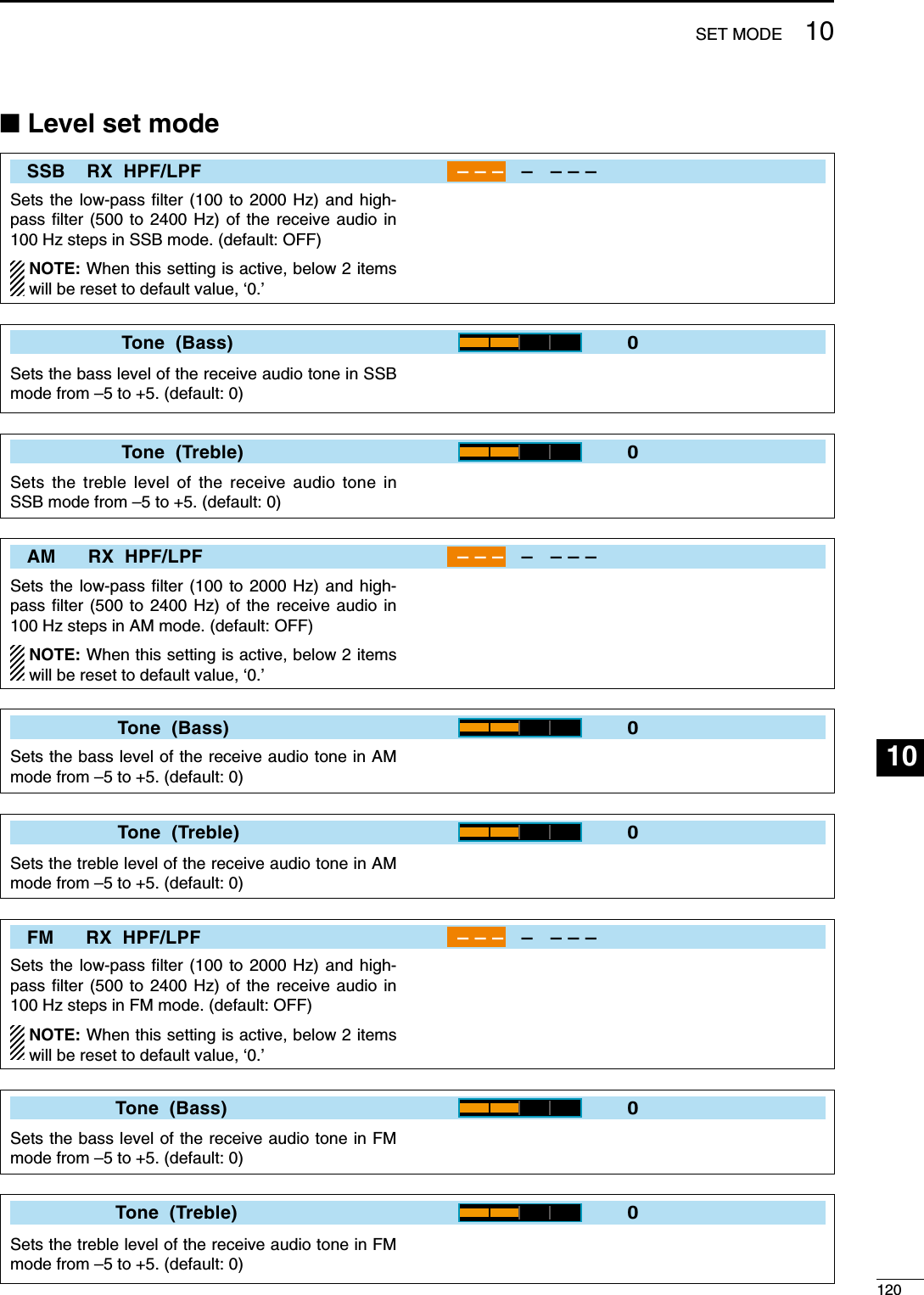
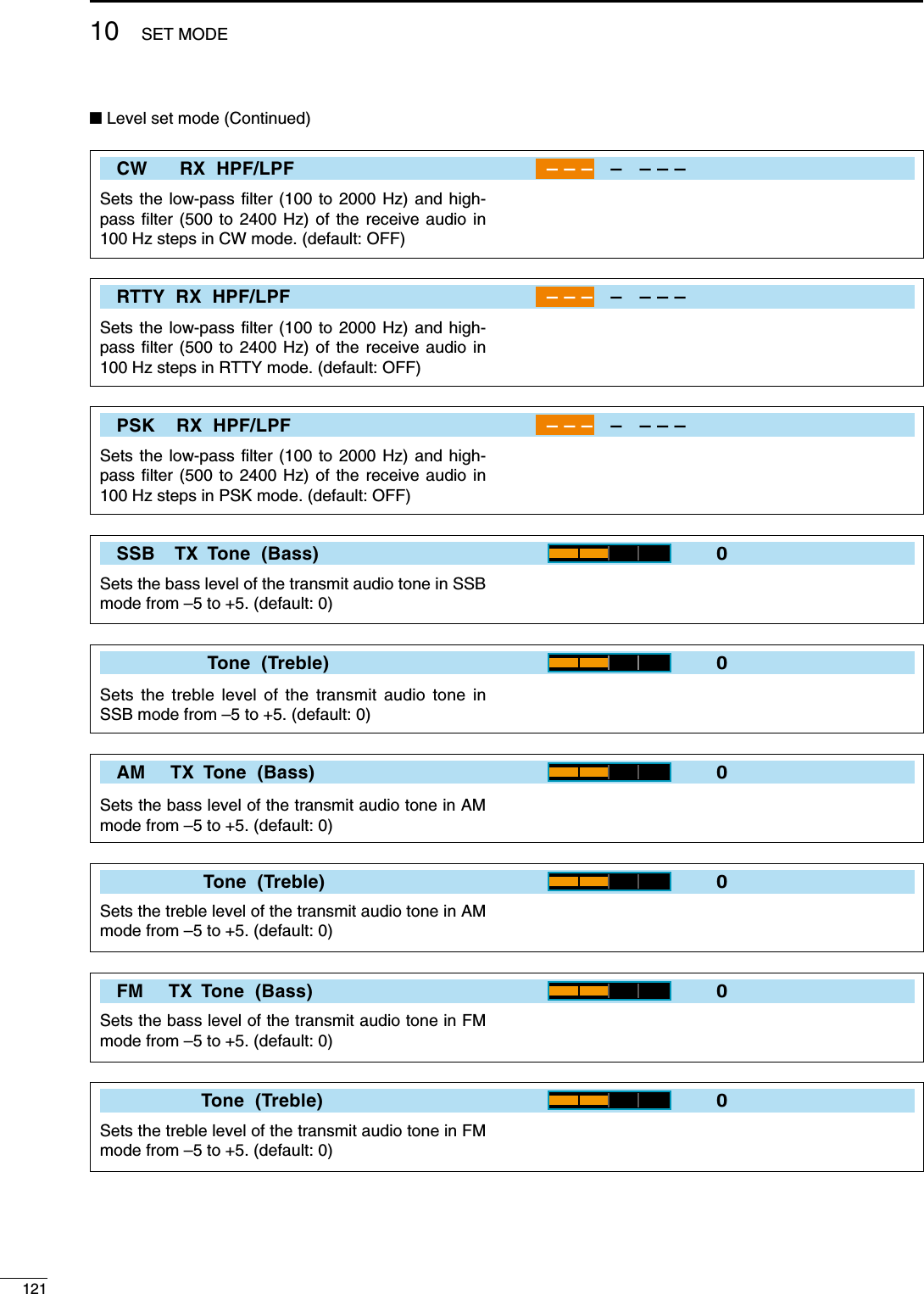
![12210SET MODE123456789101112131415161718192021SSB TBW (WIDE)100 – 2900Sets the transmission passband width to a wide setting by changing the lower and higher cut-off fre-quencies.• Lower freq. : 100 (default), 200, 300 and 500 Hz• Higher freq. : 2500, 2700, 2800 and 2900 Hz (default)SSB TBW (MID)300 – 2700Sets the transmission passband width to a middle setting by changing the lower and higher cut-off fre-quencies.• Lower freq. : 100, 200, 300 (default) and 500 Hz• Higher freq. : 2500, 2700 (default), 2800 and 2900 HzSSB TBW (NAR)500 – 2500Sets the transmission passband width to a narrow setting by changing the lower and higher cut-off fre-quencies.• Lower freq. : 100, 200, 300 and 500 Hz (default)• Higher freq. : 2500 (default), 2700, 2800 and 2900 HzDrive Gain50%Sets the drive gain level from 0% to 100% in 1% steps. (default: 50%)While talking into the microphone, keying down or transmitting, rotate the main dial so that the ALC meter reading is between 30% to 50% of the ALC scale. (p. ??)The drive gain is active for all modes other than SSB mode with speech compressor OFF.Speech Level50%Sets the voice synthesizer audio output level from 0% to 100% in 1% steps. (default: 50%)Side Tone Level50%Sets the side tone output level from 0% to 100% in 1% steps. (default: 50%)Side Tone Level LimitONTurns the side tone output level limiting capability ON and OFF. (default: ON)When this item is set to ON, the CW side tone is linked to the [AF] control until rotation of the [AF] control reaches to the specified level—further rota-tion will not increase the volume of the CW side tones.• ON : CW side tone level is limited with the [AF] control.• OFF : CW side tone level is linked to the [AF] con-trol.](https://usermanual.wiki/ICOM-orporated/307300.User-Manual-2/User-Guide-1066301-Page-39.png)
![N Level set mode (Continued)Beep Level50%Sets the key-touch beep output level from 0% to 100% in 1% steps. (default: 50%)Beep Level LimitONTurns the beep tone output level limiting capability ON and OFF for the confirmation and band edge beep tones. (default: ON)When this item is set to ON, the beep tones are linked to the [AF] control until rotation of the [AF] control reaches to the specified level—further rota-tion will not increase the volume of the beep tones.• ON : Beep level is limited with the [AF] control.• OFF : Beep level is linked to the [AF] control.12310 SET MODE](https://usermanual.wiki/ICOM-orporated/307300.User-Manual-2/User-Guide-1066301-Page-40.png)
![12410SET MODE123456789101112131415161718192021N ACC set modeUSB Audio SQLOFF (OPEN)Sets the squelch condition of the USB audio which is output from the [USB] (B) connector on the rear panel.The same audio signals are output from [USB] (B) and the ACC sockets.• The beep tones and the voice synthesizer announce-ments are not output.• The received audio output level cannot be adjusted with the [AF] control.• OFF (OPEN) : The received audio is always output regardless of the squelch condition. (default)• ON : The received audio is output ac-cording to the squelch condition (open/close).USB MOD Level50%Sets the input modulation level of the [USB] (B) con-nector from 0% to 100% in 1% steps. (default: 50%)DATA OFF MODMIC,ACCSelects the desired connector(s) for modulation input when data mode is not in use.• MIC : Use the signals from [MIC].• ACC : Use the signals from [ACC1] (pin 4).• MIC,ACC : Use the signals from [MIC] and [ACC1] (pin 4). (default)• USB : Use the signals from [USB] (B).DATA1 MODACCSelects the desired connector(s) for modulation input when data 1 mode (D1) is in use.• MIC : Use the signals from [MIC].• ACC : Use the signals from [ACC1] (pin 4). (default)• MIC,ACC : Use the signals from [MIC] and [ACC1] (pin 4).• USB : Use the signals from [USB] (B).DATA2 MODMIC,ACCSelects the desired connector(s) for modulation input when data 2 mode (D2) is in use.• MIC : Use the signals from [MIC].• ACC : Use the signals from [ACC1] (pin 4).• MIC,ACC : Use the signals from [MIC] and [ACC1] (pin 4). (default)• USB : Use the signals from [USB] (B).DATA3 MODMICSelects the desired connector(s) for modulation input when data 3 mode (D3) is in use.• MIC : Use the signals from [MIC]. (default)• ACC : Use the signals from [ACC1] (pin 4).• MIC,ACC : Use the signals from [MIC] and [ACC1] (pin 4).• USB : Use the signals from [USB] (B).](https://usermanual.wiki/ICOM-orporated/307300.User-Manual-2/User-Guide-1066301-Page-41.png)
![N ACC set mode (Continued)SEND Relay TypeLeadSelects the switching relay type for [RELAY] from Lead and MOSFET.Select the suitable relay type when connecting a non-Icom linear amplifier.• Lead : Use mechanical relay. (16 V DC/0.5 A max.; default)• MOS-FET : Use semiconductor type relay. (250 V/200 mA max.)External Meter OutputAutoSelects the desired item for an external meter indi-cation.• Auto : Outputs the receiving signal strength level during receive, and outputs the selected level (selected with [METER]), during transmit. (default)• S : Outputs the receiving signal strength level during receive.• Po : Outputs the transmitting power level dur-ing transmit.• SWR : Outputs the VSWR level during transmit.• ALC : Outputs the ALC level during transmit.• COMP : Outputs the compression level during transmit.• VD : Outputs the drain terminal voltage of the final amplifier MOSFETs.• ID : Outputs the drain current of the final am-plifier MOSFETs.External Meter Level50%Sets the output level for an external meter indication with in 0% to 100% range in 1% steps.• Approx. 2.5 V at 50% (default) setting for full-scale indi-cation. (4.7 kø impedance)REF Adjust50%Adjusts the internal reference signal frequency within 0% to 100% range in 1% steps during fre-quency calibration. NOTE: Default setting is different for each trans-ceiver.12510 SET MODE](https://usermanual.wiki/ICOM-orporated/307300.User-Manual-2/User-Guide-1066301-Page-42.png)
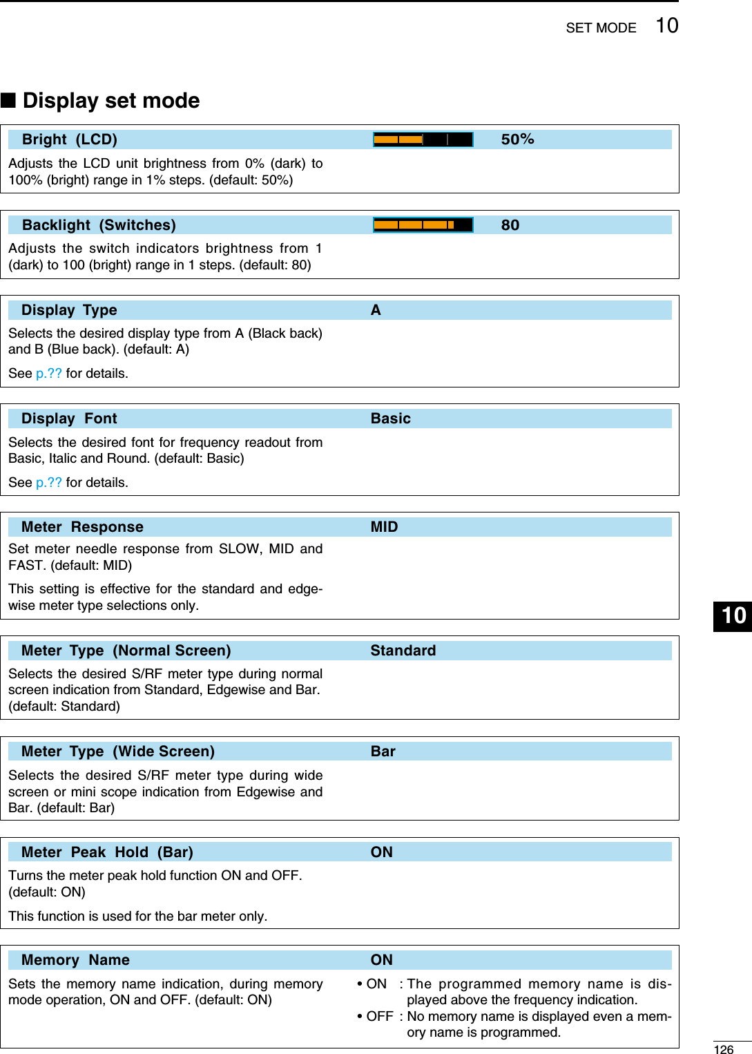
![N Display set mode (Continued) APF−Wide Popup (APF OFFON) ONSelects the pop-up display for the APF filter width from ON and OFF. (default: ON) MN−Q Popup (MN OFFON) ONEnables the pop-up indication capability when the notch filter width is changed from ON to OFF. (default: ON) Screen Saver Function 60minTurns the screen saver function ON (15, 30 or 60 minutes) and OFF. (default: 60 min.)The screen saver will activate when no operation is performed for the selected time period to protect the LCD from the “burn-in” effect. Screen Saver Type BoundSelects the screen saver type from “Bound,” “Rotation” and “Twist.” (default: Bound)The screen saver indication can be displayed for your reference while pushing and holding [PREVIEW] (F-5). Opening Message ONTurns the opening message screen indication capa-bility ON and OFF. (default: ON) My CallSets the introductory text, up to 10-character long, displayed in the opening screen.Usually, you set your call sign for the opening screen.Capital letters, numerals, some symbols (– / . @) and spaces can be used.When a PC keyboard is connected to [USB] con-nector on the front panel, the call sign can also be edited from the keyboard. In this case, an USB hub is required.z Push [EDIT] (F-5) to select the name edit condi-tion. • The cursor under the 1st character blinks.x Push [ABC] (MF6), [123] (MF7) or [Symbol] (MF7) to select the character group, then rotate the main dial to select the character. • Push [123] (MF7) or [Symbol] (MF7) to toggle numerals and symbols. • Push [Ω] (F-1) or [≈] (F-2) for cursor movement. • Push [DEL] (F-3) to delete the selected character. • Push [SPACE] (F-4) to input a space. • Pushing the transceiver’s keypad, [0]–[9], can also enter numerals.c Push [EXIT/SET] to set the name.12710 SET MODE](https://usermanual.wiki/ICOM-orporated/307300.User-Manual-2/User-Guide-1066301-Page-44.png)
![12810SET MODE123456789101112131415161718192021N Others set mode Calibration Marker OFFThis item is used for a simple frequency check of the transceiver. (default: OFF)See p. ?? for calibration procedure. NOTE: Turn the calibration marker OFF after checking the frequency of the transceiver. Beep (Confirmation) ONA beep sounds each time a switch is pushed to confirm it. This function can be turned OFF for silent operation. (default: ON)The beep output level can be set in level set mode. (p. ??) Beep (Band Edge) ON (Default)A beep sounds when an operating frequency enters or exits an amateur band. This functions indepen-dent of the confirmation beep setting (above).The beep output level can be set in level set mode. (p. ??)• OFF : Band edge beep OFF• ON (Default) : Band edge beep sounds when an operating frequency enters or exits a default amateur band. (default)• ON (User) : A beep sounds when an operating frequency enters or exits an ama-teur band that is set in BAND EDGE screen. (p. ??)• ON (User) & TX Limit : A beep sounds when an operating frequency enters or exits an ama-teur band that is set in BAND EDGE screen and TX is limited out of the band. (p. ??) Beep Sound 1000HzSets the desired key-touch beep frequency within 500 to 2000 Hz in 10 Hz steps. (default: 1000 Hz) RF/SQL Control RF+SQLThe [RF/SQL] control can be set as the RF/squelch control (default), the squelch control only (RF gain is fixed at maximum) or ‘Auto’ (RF gain control in SSB, CW and RTTY; squelch control in AM and FM).See pgs. ??, ?? for details.• RF+SQL : [RF/SQL] control as RF/squelch control (default)• SQL : [RF/SQL] control as squelch control• AUTO : [RF/SQL] control as RF gain control in SSB, CW and RTTY; squelch control in AM and FM Quick Dualwatch ONWhen this item is set to ON, pushing and holding [DUALWATCH] for 1 sec. sets the sub readout fre-quency to the main readout frequency and activates dualwatch operation.• OFF : Quick dualwatch OFF• ON : Quick dualwatch ON (default)](https://usermanual.wiki/ICOM-orporated/307300.User-Manual-2/User-Guide-1066301-Page-45.png)
![N Others set mode (Continued) Quick SPLIT ONWhen this item is set to ON, pushing and holding [SPLIT] for 1 sec. sets the unselected VFO’s readout frequency to the selected VFO’s readout frequency and activates split operation. (default: ON)See p. ?? for details. FM SPLIT Offset (HF) –0.100MHzSets the offset (difference between transmit and receive frequencies) for the quick split function. This setting is used for HF bands in FM mode only and is used to input the repeater offset for an HF band.The offset frequency can be set from –9.999 to +9.999 MHz in 1 kHz steps. (default: –0.100 MHz) FM SPLIT Offset (50M) –0.500MHzSets the offset (difference between transmit and re-ceive frequencies) for the quick split function. This setting is used for 50 MHz band FM mode only, and is used to input the repeater offset for the 50 MHz band.The offset frequency can be set from –9.999 to +9.999 MHz in 1 kHz steps. (default: –0.500 MHz) SPLIT LOCK OFFWhen this item is ON, the main dial can be used to adjust the transmit frequency while pushing [XFC] even while the lock function is activated. (default: OFF)See pgs. ??, ?? for split frequency operation details. Tuner (Auto Start) OFFThe internal antenna tuner has an automatic start capability which starts tuning if the SWR is higher than 1.5–3:1.• OFF : The tuner remains OFF even when the SWR is poor (1.5–3:1). (default)• ON : Automatic tune starts even when the tuner is turned OFF during HF bands operation. Tuner (PTT Start) OFFTuning of the internal antenna tuner can be started automatically at the moment the PTT is pushed after the operating frequency is changed (more than 1% from last-tuned frequency). (default: OFF)12910 SET MODE](https://usermanual.wiki/ICOM-orporated/307300.User-Manual-2/User-Guide-1066301-Page-46.png)
![13010SET MODE123456789101112131415161718192021 Tuner Preset Memory Clear <Select>The preset memory* of the selected antenna can be cleared with pushing [CLR] (F-5).* The variable capacitor settings are memorized as a preset point for each frequency range (100 kHz steps) after the tuner matches an antenna.• ANT1 Push [CLR] : The preset memory of the antenna that is connected to [ANT 1] is cleared after push-ing [CLR] (F-5).• ANT2 Push [CLR] : The preset memory of the antenna that is connected to [ANT 2] is cleared after push-ing [CLR] (F-5). [ANT] Switch AutoYou can set the antenna connector selection to automatic, manual or non-selection (when using 1 antenna only).• Auto : Antenna switch is activated and the band memory memorizes the selected an-tenna. (default) See p. ?? for details.• Manual : Antenna switch is activated and selects an antenna manually.• OFF : Antenna switch is not activated and does not function. The [ANT1] connector is al-ways selected. Transverter Function AutoSelects the transverter operation condition from Auto and ON. (default: Auto)• ON : Turn the transverter operation ON.• Auto : The transceiver turns into transverter op-eration condition when 2 to 13.8 V DC is applied to [ACC2] pin 6. Transverter Offset 16.000MHz (14.100.030.100.0)Sets the desired offset frequency for the transverter operation within 0.000 to 99.999 MHz in 1 kHz steps. (default: 16.000 MHz) RTTY Mark Frequency 2125Selects the RTTY mark frequency. RTTY mark frequency is switched between 1275, 1615 and 2125 Hz. (default: 2125 Hz)2125 Hz is automatically selected when the internal RTTY decoder is used. RTTY Shift Width 170Selects the RTTY shift width. There are 3 selectable values: 170, 200 and 425 Hz. (default: 170 Hz)170 Hz is automatically selected when the internal RTTY decoder is used.](https://usermanual.wiki/ICOM-orporated/307300.User-Manual-2/User-Guide-1066301-Page-47.png)
![N Others set mode (Continued) RTTY Keying Polarity NormalSelects the RTTY keying polarity. Normal or reverse keying polarity can be selected. (default: Normal)When reverse polarity is selected, Mark and Space are reversed.• Normal : Key open/close = Mark/Space• Reverse : Key open/close = Space/Mark PSK Tone Frequency 1500Selects the desired PSK tone frequency for the PSK reception from 1000, 1500 and 2000 Hz. (default: 1500 Hz) SPEECH Language EnglishSelects the speech language from English and Japanese. (default: English) SPEECH Speed HIGHSelects the speech speed from HIGH (faster) and LOW (slower). (default: HIGH) SPEECH S-Level ONThe IC-7600 speech processor can announce fre-quency, mode and signal level. Signal level an-nouncement can be deactivated if desired.(default: ON)When “OFF” is selected, the signal level is not an-nounced. SPEECH [MODE] Switch OFFSelects the operating mode speech capability when a mode switch is pushed; ON or OFF. (default: OFF)When “ON” is selected, the selected operating mode is announced when a mode switch is pushed. [SPEECH/LOCK] Switch SPEECH/LOCKSelects the [SPEECH/LOCK] switch action. • SPEECH/LOCK : (Push) The voice synthesizer function is activated. (Push and hold) The dial lock function is turned ON or OFF.• LOCK/SPEECH : (Push) The dial lock function is turned ON or OFF. (Push and hold) The voice syn-thesizer function is activated.13110 SET MODE](https://usermanual.wiki/ICOM-orporated/307300.User-Manual-2/User-Guide-1066301-Page-48.png)
![13210SET MODE123456789101112131415161718192021 Memopad Numbers 5Sets the number of memo pad channels available.5 or 10 memo pads can be selected. (default: 5) MAIN DIAL Auto TS HIGHSets the auto tuning step function for the main dial. When rotating the main dial rapidly, the tuning step automatically changes several times as selected. There are 2 type of auto tuning steps: HIGH (Fastest) and LOW (Faster). (default: HIGH)• HIGH : Auto tuning step is turned ON. Fastest tun-ing step during rapid rotation. (default)• LOW : Auto tuning step is turned ON. Faster tun-ing step during rapid rotation.• OFF : Auto tuning step is turned OFF. MIC Up/Down Speed HIGHSets the rate at which frequencies are scanned when the microphone [UP]/[DN] switches are pushed and held. HIGH or LOW can be selected.• HIGH : High speed (default; 50 tuning steps/sec.)• LOW : Low speed (25 tuning steps/sec.) Quick RIT/∂TX Clear OFFSelects the RIT/∂TX frequency clearing instruction with [CLEAR].• ON : Clears the RIT/∂TX frequency when [CLEAR] is pushed momentarily.• OFF : Clears the RIT/∂TX frequency when [CLEAR] is pushed and held for 1 sec. (default) [NOTCH] Switch (SSB) Auto/ManualSelects notch functions for SSB mode operation from Auto, Manual and Auto/Manual.• Auto : Only the auto notch can be used.• Manual : Only the manual notch can be used.• Auto/Manual : Both the auto and manual notch can be used. (default) [NOTCH] Switch (AM) Auto/ManualSelects notch functions for AM mode operation from Auto, Manual and Auto/Manual.• Auto : Only the auto notch can be used.• Manual : Only the manual notch can be used.• Auto/Manual : Both the auto and manual notch can be used. (default) SSB/CW Synchronous Tuning OFFSelects the displayed frequency shift function from ON and OFF. (default: OFF)When this function is activated, the audio pitch or tones of the received signal will remain the same even when the operating mode is changed between SSB and CW. The amount of frequency shift may differ accord-ing to the CW pitch setting.• ON : The displayed frequency shifts when the op-erating mode is changed between SSB and CW.• OFF : The displayed frequency does not shift.](https://usermanual.wiki/ICOM-orporated/307300.User-Manual-2/User-Guide-1066301-Page-49.png)
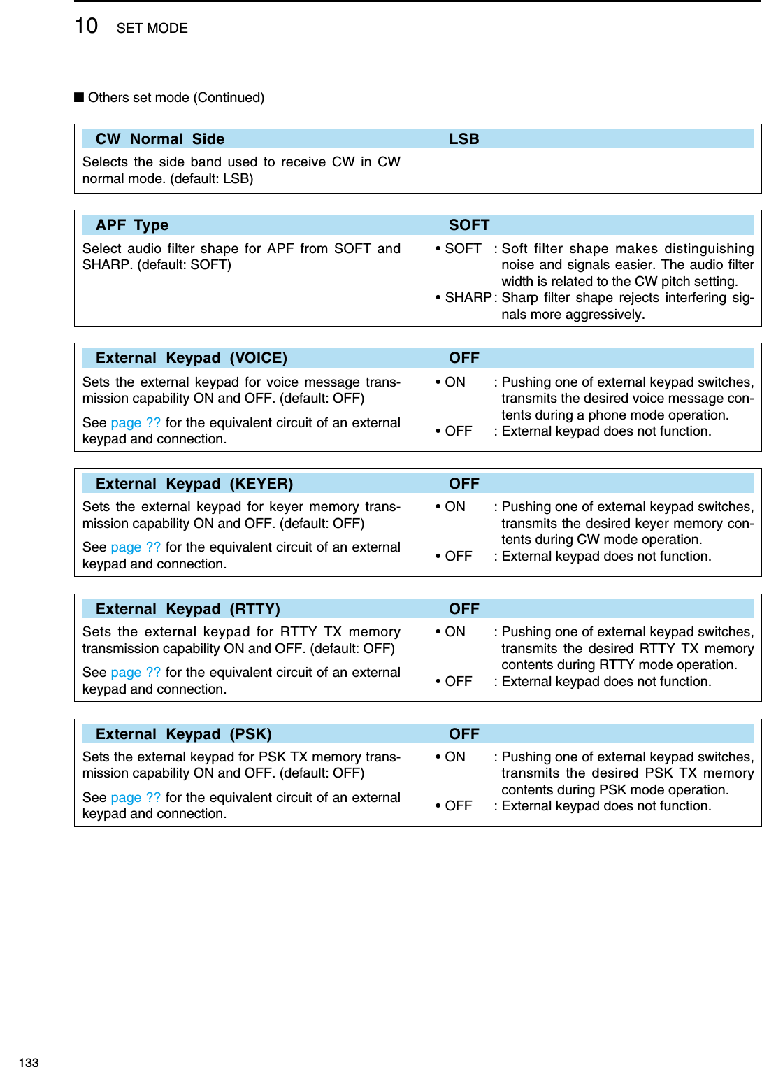
![13410SET MODE123456789101112131415161718192021 Keyboard [F-1]–[F-4] (VOICE) OFFSets the voice message transmission capability ON and OFF when one of [F-1]−[F-4] key of the key-board that is connected to the [USB] (A) connector on the front panel is pushed. (default: OFF)• ON : Pushing one of [F-1]−[F-4] key of the con-nected keyboard transmits the desired voice message contents during a phone mode operation.• OFF : [F-1]−[F-4] key of the connected key-board does not function. Keyboard [F-1]–[F-4] (KEYER) OFFSets the keyer memory transmission capability ON and OFF when one of [F-1]−[F-4] key of the key-board that is connected to the [USB] (A) connector on the front panel is pushed. (default: OFF)• ON : Pushing one of [F-1]−[F-4] key of the con-nected keyboard transmits the desired keyer memory contents during CW mode operation. • OFF : [F-1]−[F-4] key of the connected key-board does not function. CI–V Baud Rate AutoSets the CI-V data transfer rate. 300, 1200, 4800, 9600, 19200 bps and “Auto” are available.(default: Auto)When “Auto” is selected, the baud rate is auto-matically set according to the data rate of connected controller. CI–V Address 7AhTo distinguish equipment, each CI-V transceiver has its own Icom standard address in hexadecimal code. The IC-7600’s address is 7Ah.When 2 or more IC-7600’s are connected to an op-tional CT-17 CI-V LEVEL CONVERTER, rotate the main dial to select a different address for each IC-7600; the range is 01h to 7Fh. CI–V Transceive ONTransceive operation is possible with the IC-7600 connected to other Icom HF transceivers or receivers.When “ON” is selected, changing the frequency, operating mode, etc. on the IC-7600 automatically changes those of connected transceivers (or receiv-ers) and vice versa. USB Serial Function CI-VSelect [USB] connector output data format from CI-V and Decode.• CI-V : Outputs data in CI-V format. (default)• Decode : Outputs decoded contents in ASCII code format.](https://usermanual.wiki/ICOM-orporated/307300.User-Manual-2/User-Guide-1066301-Page-51.png)
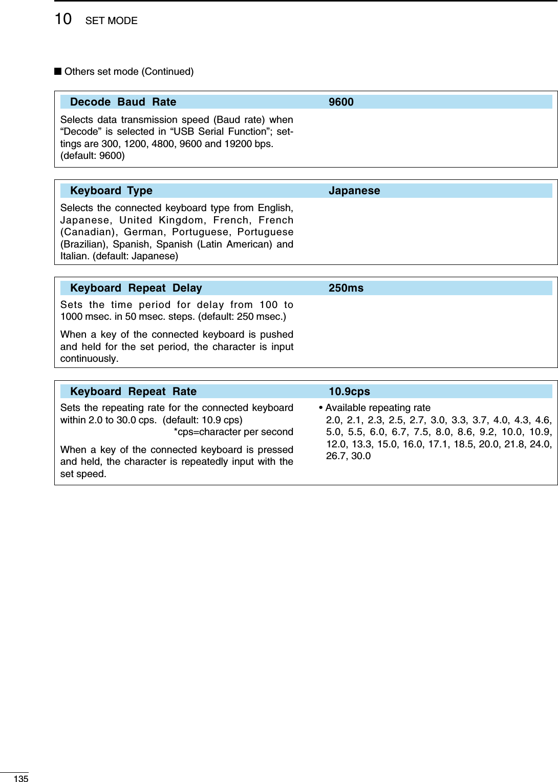
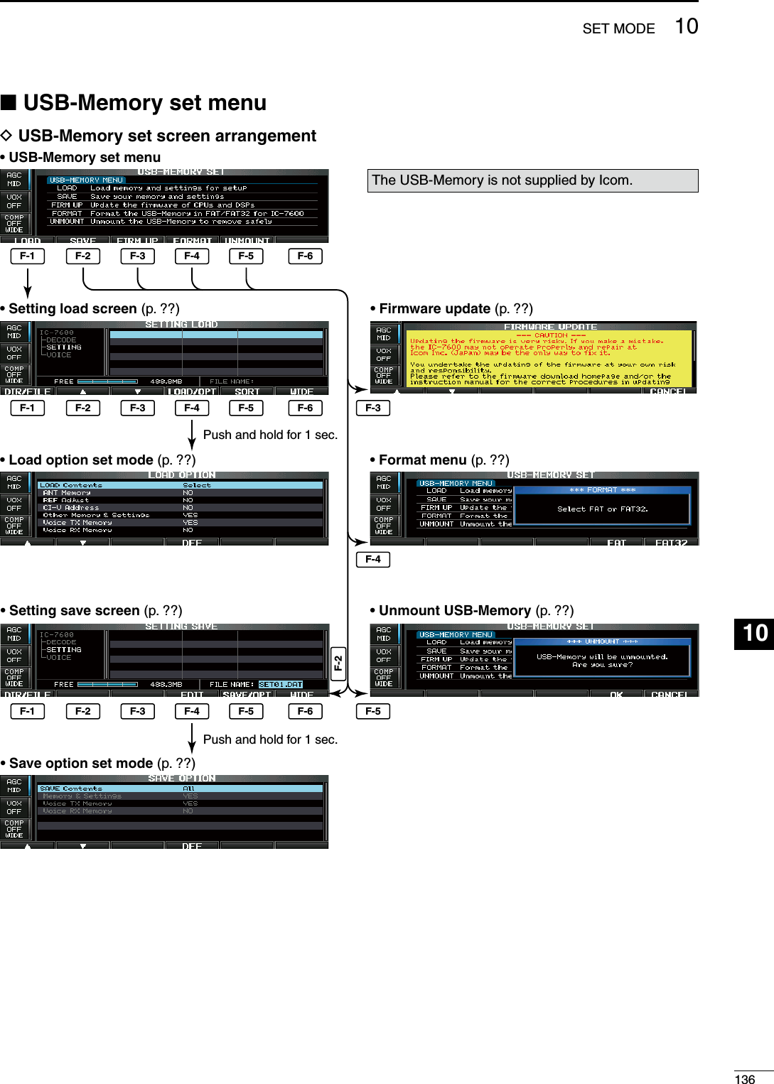
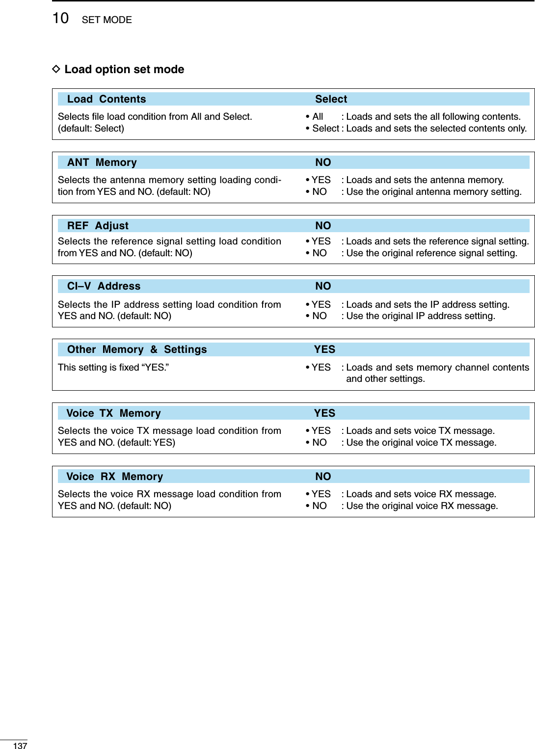
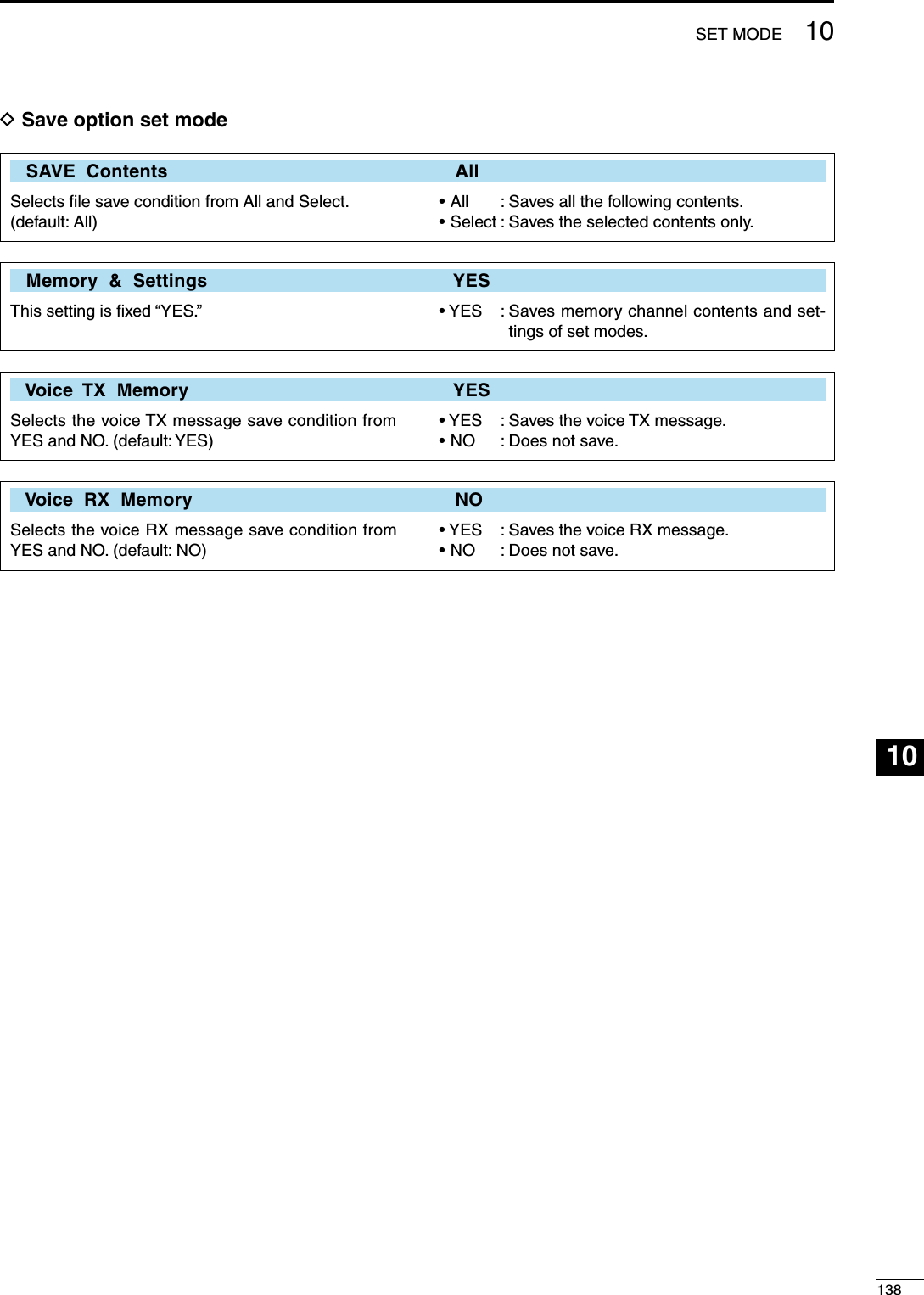
![N File savingF-1 F-2 F-4F-5 F-6EXIT/SET Main dialUSBSAVE EDITSymbol ABC123SAVE/OPTDIR/FILEOKWhen a PC keyboard is connected to [USB] con-nector on the front panel, the file name can also be edited from the keyboard. In this case, an USB hub is required.Memory channel contents, set mode settings, etc. can be saved into the USB-Memory for backup.q During set mode menu screen indication, push [USB] (F-6) to select USB-Memory set menu screen.w Push [SAVE] (F-2) to select setting save screen.e Change the following conditions if desired. • File name: z Push [EDIT] (F-4) to select file name edit con-dition. • Push [DIR/FILE] (F-1) several times to select the file name, if necessary. x Push [ABC] (MF6), [123] (MF7) or [Symbol] (MF7) to select the character group, then ro-tate the main dial to select the character. • [ABC] (MF6): A to Z (capital letters); [123] (MF7): 0 to 9 (numerals); [Symbol] (MF7): ! # $ % & ’ ` ^ – ( ) { } _ ~ @ can be selected. • Push [Ω] (F-1) to move the cursor left, push [≈] (F-2) to move the cursor right, push [DEL] (F-3) to delete a character and push [SPACE] (F-4) to insert a space. c Push [EXIT/SET] to set the file name. • Save option z Push and hold [SAVE/OPT] (F-5) for 1 sec. to enter save option set mode. x Push [Y] (F-1) or [Z] (F-2) to select the item, then rotate the main dial to select the desired setting. (see p. ?? for details) • Push and hold [DEF] (F-4) for 1 sec. to select the default setting. c Push [EXIT/SET] to return to the previous in-dication. • Saving location z Push [DIR/FILE] (F-1) to select tree view screen. x Select the desired directory or folder in the USB-Memory. • Push [Ω ≈] (F-4) to select the upper directory. • Push [Y] (F-2) or [Z] (F-3) to select folder in the same directory. • Push and hold [Ω ≈] (F-4) for 1 sec. to select a folder in the directory. • Push [REN] (MF5) to rename the folder. • Push and hold [DEL] (MF6) for 1 sec. to delete the folder. • Push and hold [MAKE] (MF7) for 1 sec. to making a new folder. (Edit the name with the same man-ner as the “• File name” above.) c Push [DIR/FILE] (F-1) twice to select the file name.r Push [SAVE/OPT] (F-5). • Confirmation screen appears.t Push [OK] (F-5) to save. • After saving is completed, return to USB-Memory set menu automatically.13910 SET MODE](https://usermanual.wiki/ICOM-orporated/307300.User-Manual-2/User-Guide-1066301-Page-56.png)
![14010SET MODE123456789101112131415161718192021N File loadingF-1 F-2 F-3 F-5F-4 F-6EXIT/SET Main dialUSBLOAD/OPTLOAD OKBy loading the saved setting file from the USB-Memory, you can easily set up another IC-7600—several operators settings can easily be applied to one IC-7600.q During set mode menu screen indication, push [USB] (F-6) to select USB set menu screen.w Push [LOAD] (F-1) to select setting load screen.e Push and hold [LOAD/OPT] (F-4) for 1 sec. to select load option set mode, then set the desired loading conditions, if desired. • See page ?? for details.r Push [EXIT/SET] to set.t Push [Y] (F-2) or [Z] (F-3) to select the desired setting file.y Push [LOAD/OPT] (F-4). • Confirmation screen appears.u Push [OK] (F-5) to starts loading. • After the loading is completed, the message dialog, “Reboot the IC-7600,” appears.i Turn the transceiver power OFF then ON to make the setting effective.](https://usermanual.wiki/ICOM-orporated/307300.User-Manual-2/User-Guide-1066301-Page-57.png)
![N Changing a file nameF-1 F-2 F-3 EXIT/SET Main dialDIR/FILERENSymbol ABC123When a PC keyboard is connected to [USB] con-nector on the front panel, the file name can also be edited from the keyboard. In this case, an USB hub is required.The file name, saved in the USB-Memory, can be re-named from the transceiver as desired.q During setting save screen indication, push [DIR/FILE] (F-1) to select tree view screen. • Push [Y] (F-2) or [Z] (F-3) to select the desired folder. • “DECODE,” “SETTING” and “VOICE” folders are avail-able as the default. • After the folder is selected, push and hold [Ω ≈] (F-4) for 1 sec. to display content folder(s), if available.w Push [DIR/FILE] (F-1) to select file list screen.e Push [Y] (F-2) or [Z] (F-3) to select the desired file.r Push [REN] (MF5) momentarily to select the file name edit condition.t Push [ABC] (MF6), [123] (MF7) or [Symbol] (MF7) to select the character group, then rotate the main dial to select the character. • [ABC] (MF6): A to Z (capital letters); [123] (MF7): 0 to 9 (numerals); [Symbol] (MF7): ! # $ % & ‘ ` ^ – ( ) { } _ ~ @ can be selected. • Push [Ω] (F-1) to move the cursor left, push [≈] (F-2) to move the cursor right, push [DEL] (F-3) to delete a character and push [SPACE] (F-4) to insert a space. • Pushing the transceiver’s keypad, [0]–[9], can also enter numerals.y Push [EXIT/SET] to set the file name.14110 SET MODE](https://usermanual.wiki/ICOM-orporated/307300.User-Manual-2/User-Guide-1066301-Page-58.png)
![14210SET MODE123456789101112131415161718192021N Deleting a file F-1 F-2 F-3 F-5DIR/FILEDELOKN Unmounting USB-MemoryF-5OKUNMOUNTRECOMMENDATION! Deleting the setting file is ir-reversible. Confirm the contents before deleting a setting file!q During setting save screen indication, push [DIR/FILE] (F-1) to select tree view screen. • Push [Y] (F-2) or [Z] (F-3) to select the desired folder. • “DECODE,” “SETTING” and “VOICE” folders are avail-able as the default. • After the folder is selected, push and hold [Ω ≈] (F-4) for 1 sec. to display content folder(s), if available.w Push [DIR/FILE] (F-1) to select file list screen.e Push [Y] (F-2) or [Z] (F-3) to select the desired file to be deleted.r Push and hold [DEL] (MF6) for 1 sec. • Confirmation screen appears.t Push [OK] (F-5) to delete. • After the deleting, return to setting save screen auto-matically.CAUTION! When removing the USB-Memory, un-mount operation is recommended. If you do not unmount the memory in this case, data in the USB memory may be corrupted.q During USB-Memory set menu screen indication, push and hold [UNMOUNT] (F-5) for 1 sec. • Confirmation screen appears.w Push [OK] (F-5) to unmount the USB-Memory.e After the indicator above [USB] (A) connector goes off, remove the USB-Memory.](https://usermanual.wiki/ICOM-orporated/307300.User-Manual-2/User-Guide-1066301-Page-59.png)
![N Formatting the USB-MemorySaved data in the USB-Memory can be erased.IMPORTANT! Formatting erases all saved data in the USB-Memory. Making a backup file on your PC is recommended.q During USB-Memory set menu screen indication, push and hold [FORMAT] (F-4) for 1 sec. • Confirmation screen appears.w Push [FAT] (F-5) or [FAT32] (F-6) to select the for-mat type, FAT or FAT32, respectively. • Confirmation screen appears.e Push [OK] (F-5) to format. • Push [CANCEL] (F-6) to cancel.r Returns to USB-Memory set menu indication auto-matically.NOTE: If no USB-Memory is inserted and [FORMAT] (F-4) is selected as in step q, an error message appears as below.MMM NO USB-MEMORY IS FOUND MMMCheck the following: • Insert a USB-Memory • The USB-Memory type14310 SET MODE](https://usermanual.wiki/ICOM-orporated/307300.User-Manual-2/User-Guide-1066301-Page-60.png)
![D Transceiver powerPROBLEM POSSIBLE CAUSE SOLUTION REF.Power does not come on when the [POWER] switch is pushed.• Power cable is improperly connected.• The internal power supply is turned OFF.• Circuit breaker is tripped.• Re-connect the AC power cable correctly.• Turn the internal power supply ON.• Check for the cause, then re-set the circuit breaker.p. ??p. ??—D Transmit and receivePROBLEM POSSIBLE CAUSE SOLUTION REF.No sounds from the speaker. • Volume level is too low.• The squelch is closed.• The transceiver is in transmit.• Rotate [AF] clockwise to obtain a suitable lis-tening level.• Turn [SQL] to 10 o’clock position to open the squelch.• Push [TRANSMIT] to receive or check the SEND line of an external unit, if connected.p. ??p. ??p. ??Sensitivity is too low, and only strong signals are audible.• The antenna is not connected properly.• The antenna for another band is selected.• The antenna is not properly tuned.• The attenuator is activated.• Re-connect to the antenna connector.• Select an antenna suitable for the operating frequency.• Push and hold [TUNER] for 1 sec. to manually tune the antenna.• Push [ATT] (MF4) several times to select “ATT OFF.”p. ??Received audio is unclear or distorted.• Wrong operating mode is selected.• PBT function is activated.• Noise blanker is turned ON when receiving a strong signal.• Preamp is activated.• The noise reduction is activated and the [NR] control is too far clockwise.• Select a suitable operating mode.• Push and hold [PBT-CLR] for 1 sec. to reset the function.• Push [NB] to turn the noise blanker OFF.• Push [P.AMP] (MF3) once or twice to turn the function OFF.• Set the [NR] control for maximum readability.p. ??The [ANT] switch does not function• The antenna switch has not been activated. • Set the antenna switch in set mode to “Auto” or “Manual.”p. ??Transmitting is impossible. • The operating frequency is not inside a ham band.• Set the frequency to be in a ham band. p. ??Output power is too low. • [RF PWR] is set too far counterclockwise• [DRIVE] is set too far counterclockwise• [MIC] is set too far counterclockwise• The antenna for another band is selected.• The antenna is not properly tuned.• Rotate [RF PWR] clockwise.• Set [DRIVE] to a suitable position.• Set [MIC] to a suitable position.• Select an antenna suitable for the operating frequency.• Push and hold [TUNER] for 1 sec. to manually tune the antenna.p. ??No contact can be made with another station.• RIT or ∂TX function is activated.• Split frequency function is activated.• Push [RIT] or [∂TX] to turn the function OFF.• Push [SPLIT] to turn the function OFF.p. ??Transmit signal is unclear or distorted.• [MIC] is set too far clockwise • Set [MIC] to a suitable position. p. ??Repeater cannot be ac-cessed.• Split frequency function is not activated.• Programmed subaudible tone frequency is wrong.• Push [SPLIT] to to turn the function ON• Reset the frequency using set mode.p. ??N TroubleshootingThe following chart is designed to help you correct problems which are not equipment malfunctions.If you are unable to locate the cause of a problem or solve it through the use of this chart, contact you nearest Icom Dealer or Service Center.11144MAINTENANCE123456789101112131415161718192021](https://usermanual.wiki/ICOM-orporated/307300.User-Manual-2/User-Guide-1066301-Page-61.png)
![N Main dial brake adjustment The tension of the main dial may be adjusted to suit your preference.The brake adjustment is located on the bottom side of the front panel. See the figure at left.Slide the brake adjustment to a comfortable tension level while turning the dial continuously and evenly in one direction.Main dialBrakeadjustment LightHeavyD ScanningPROBLEM POSSIBLE CAUSE SOLUTION REF.Programmed scan does not stop.• Squelch is open. • Set [SQL] to the threshold point. p. ??Programmed scan does not start.• The same frequencies have been programmed in scan edge memory channels P1 and P2.• Program different frequencies in scan edge memory channel P1 and P2.p. ??Memory scan does not start • 2 or more memory channels have not been programmed.• Program more than 2 memory channels. p. ??Select memory scan does not start• 2 or more memory channels have not been designated as select channels.• Designate more than 2 memory channels as select channels for the scan.p. ??D DisplayPROBLEM POSSIBLE CAUSE SOLUTION REF.The displayed frequency does not change properly.• The dial lock function is activated.• A set mode screen is selected.• The internal CPU has malfunctioned.• Push [LOCK] to turn the function OFF.• Push [EXIT/SET] several times to exit the set mode screen.• Reset the CPU.p. ??D Format USB-MemoryPROBLEM POSSIBLE CAUSE SOLUTION REF.Format error appears when formatting in FAT32• The inserted USB-Memory capacity is smaller than 64 MB.• Insert a USB-Memory larger than 64 MB or select the FAT format.p. ??Format error appears when formatting in FAT• The inserted USB-Memory capacity is larger than 2 GB.• Insert a USB-Memory smaller than 2 GB or select the FAT32 format.p. ??14511 MAINTENANCE](https://usermanual.wiki/ICOM-orporated/307300.User-Manual-2/User-Guide-1066301-Page-62.png)
![N SWR readingThe SWR meter indicates the SWR over the trans-mission line in all modes.q Push [TUNER] to turn the antenna tuner OFF.w Push and hold [METER] (MF2) for 1 sec. to display multi-function meter.e Push [RTTY/PSK] once or twice to select RTTY mode.r Push [TRANSMIT].t Rotate [RF POWER] clockwise past the 12 o’clock position for more than 30 W output power.y Read the SWR on the SWR meter gage.u Push [EXIT/SET] to close multi-function meter.The built-in antenna tuner matches the transmitter to the antenna when the SWR is lower than 3 : 1.[RF POWER][METER]TRANSMIT TUNERRTTY/PSKN Screen type and font selections2 types of screen images and 3 types of frequency readout indication fonts are available in the IC-7600.q Push [EXIT/SET] several times to close multi-func-tion screen, if necessary.w Push [SET] (F-6) to select set mode menu screen.e Push [DISP] (F-3) to enter display set mode.r Push [Y] (F-1) or [Z] (F-2) to select “Display Type” item when selecting the screen image, se-lect “Display Font” when selecting the frequency readout indication font.t Rotate the main dial to select the desired screen image or font. • Screen image is selectable from A (Black back) and B (Blue back). • Basic, Italic and Round are available for the frequency readout font.y Push [EXIT/SET] twice to exit from display set mode.F-1 F-2 F-3 F-4F-6DISPEXIT/SET [DIAL]SETDEF• Screen image example— Display Type: B, Display Font: ItalicBetter than 1.5:114611MAINTENANCE123456789101112131415161718192021](https://usermanual.wiki/ICOM-orporated/307300.User-Manual-2/User-Guide-1066301-Page-63.png)
![N Frequency calibration (approximate)A very accurate frequency counter is required to calibrate the frequency of the transceiver. However, a rough check may be performed by receiving radio station WWV, WWVH, or other standard frequency signals. CAUTION: The IC-7600 has been thoroughly ad-justed and tested at the factory before being shipped. You should not have to re-calibrate it.q Push [SSB] to select USB mode.w Push and hold [PBT-CLR] for 1 sec. to clear the PBT setting and make sure that the RIT/∂TX func-tion is not activated.e Set the frequency to the standard frequency station minus 1 kHz. • When receiving WWV or WWVH (at 15.00000 MHz) as a standard frequency, set the operating frequency for 14.99900 MHz. • Other standard frequencies can be used.r Push [EXIT/SET] several times to close a multi-function screen, if necessary.t Push [SET] (F-6) to select set mode menu screen.y Push [OTHERS] (F-5) to enter others set mode.u Push [Y] (F-1) several times to select the “Calibration Marker” item.i Rotate the main dial clockwise to turn the calibra-tion marker ON.o Push [EXIT/SET] once to return to set mode menu screen.!0 Push [ACC] (F-2) to enter accessory set mode.!1 Push [Z] (F-2) several times to select the “REF Adjust” item.!2 Rotate the main dial to adjust for a zero beat with the received standard signal as shown at right. • Zero beat means that two signals are exactly the same frequency, resulting in a single tone being emitted.!3 Turn the calibration marker OFF in others set mode.!4 Push [EXIT/SET] twice to exit set mode.F-1 F-2F-6EXIT/SET [DIAL]SETF-5OTHERSACCSSBPBT-CLR/• Calibration marker item• REF Adjust item14711 MAINTENANCE](https://usermanual.wiki/ICOM-orporated/307300.User-Manual-2/User-Guide-1066301-Page-64.png)
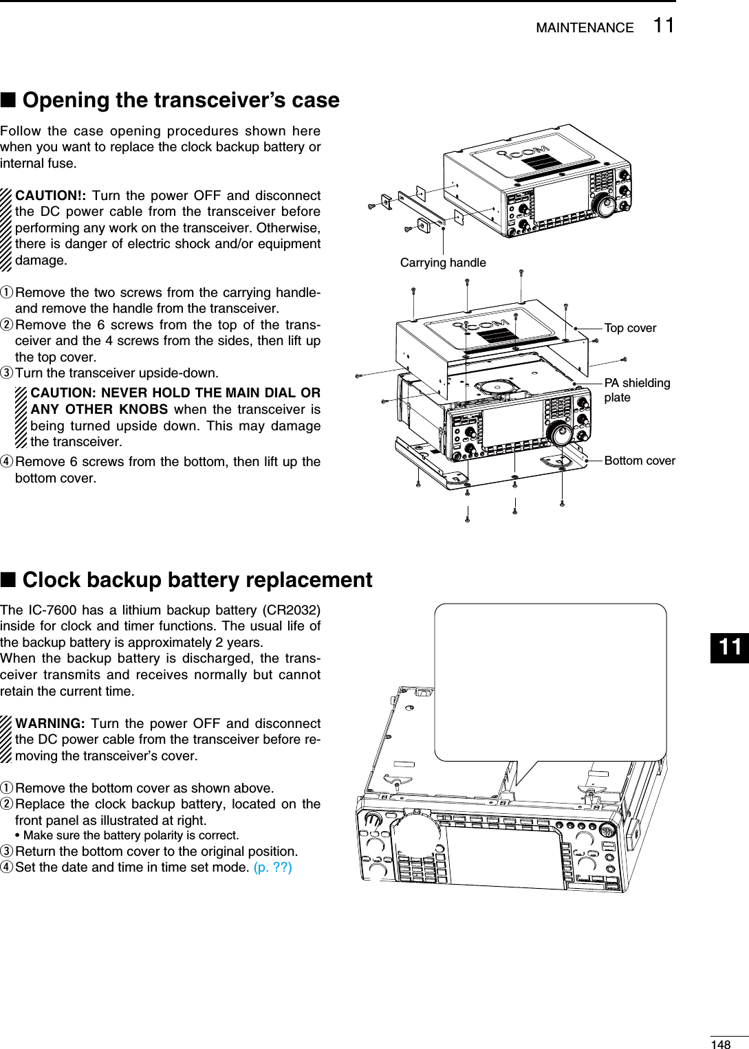
![N Fuse replacementIf a fuse blows or the transceiver stops functioning, try to find the source of the problem, and replace the damaged fuse with a new, adequately rated fuse.WARNING: Turn the power OFF and disconnect the DC power cable from the transceiver before re-moving the transceiver’s cover.D DC power cable fuse replacementRefer the figure illustrated at right for the DC power cable fuse replacement.D Circuitry fuse replacementThe 13.8 V DC from the DC power cable is applied to all units in the IC-7600, except for the power ampli-fier, through the circuitry fuse. This fuse is installed in the PA unit.q Remove the to top cover as shown left.w Remove the 11 screws, then remode the bottom cover and the PA shielding plate as shown at right.e Replace the circuitry fuse as shown in the diagram as at right.r Replace the PA shielding plate, top cover and screws to their original position.N Resetting the CPUq Turn the transceiver power OFF in advance.w While pushing and holding [F-INP ENT] and [MW], push [POWER] to turn power ON. • The internal CPU is reset. • The CPU start-up takes approx. 5 sec. • The transceiver displays its initial VFO frequencies when resetting is complete.e Correct the set mode settings after resetting, if de-sired.NOTE: Resetting CLEARS all programmed con-tents in memory channels and returns programmed values in set mode to default values.The IC-7600 has two fuses (DC power cable fuses) installed for transceiver protection.• DC power cable fuses .............................. ATC 30 A • Circuitry fuse .............................................. ATC 5 AATC 30 A fusePA shielding plateATC 5 A fusePOWER F-INP ENT MWi7600ALL CLEAR14911 MAINTENANCE](https://usermanual.wiki/ICOM-orporated/307300.User-Manual-2/User-Guide-1066301-Page-66.png)
![N About protection indicationsThe IC-7600 has a 2-step protection function to pro-tect the final power amplifiers.The protector monitors the power amplifier tempera-ture and activates when the temperature becomes extremely high.• Power down transmission Reduces the transmit output power to 100 W. “LMT” appears beside the transmit indicator during transmit.• Transmission inhibit Deactivates the transmitter. The transmit indicator is displayed in gray during transmit. When the protector is activated, wait until the power amplifier cools down using the transceiver in stand-by or receive condition.NOTE: DO NOT turn the transceiver power OFF when the protector is ON. If you do, the cooling fan will not function and it will take longer to cool the transceiver.The power amplifier temperature can be monitored in the multi-function meter, TEMP gauge.N Screen saver functionThe IC-7600 has a screen saver function to protect the LCD from the “burn-in” effect.q Push [EXIT/SET] several times to close a multi-function screen, if necessary.w Push [SET] (F-6) to select set mode menu screen.e Push [DISP] (F-3) to enter display set mode.r Push [Y] (F-1) or [Z] (F-2) several times to select the “Screen Saver Function” item.t Rotate the main dial to select the desired time period for the screen saver activation from 15, 30, 60 min. and OFF. • Deactivate the screen saver with “OFF” selection.y Push [Z] (F-2) to select the “Screen Saver Type” item.u Rotate the main dial to select the screen saver type from “Bound,” “Rotation” and “Twist.” • Push and hold [PREVIEW] (F-5) to display the indica-tion for your reference.i Push [EXIT/SET] twice to exit set mode.Check the temperatureF-1 F-2 F-3F-6DISPEXIT/SET [DIAL]SETF-5PREVIEWWhen “Twist.” is selected15011MAINTENANCE123456789101112131415161718192021](https://usermanual.wiki/ICOM-orporated/307300.User-Manual-2/User-Guide-1066301-Page-67.png)
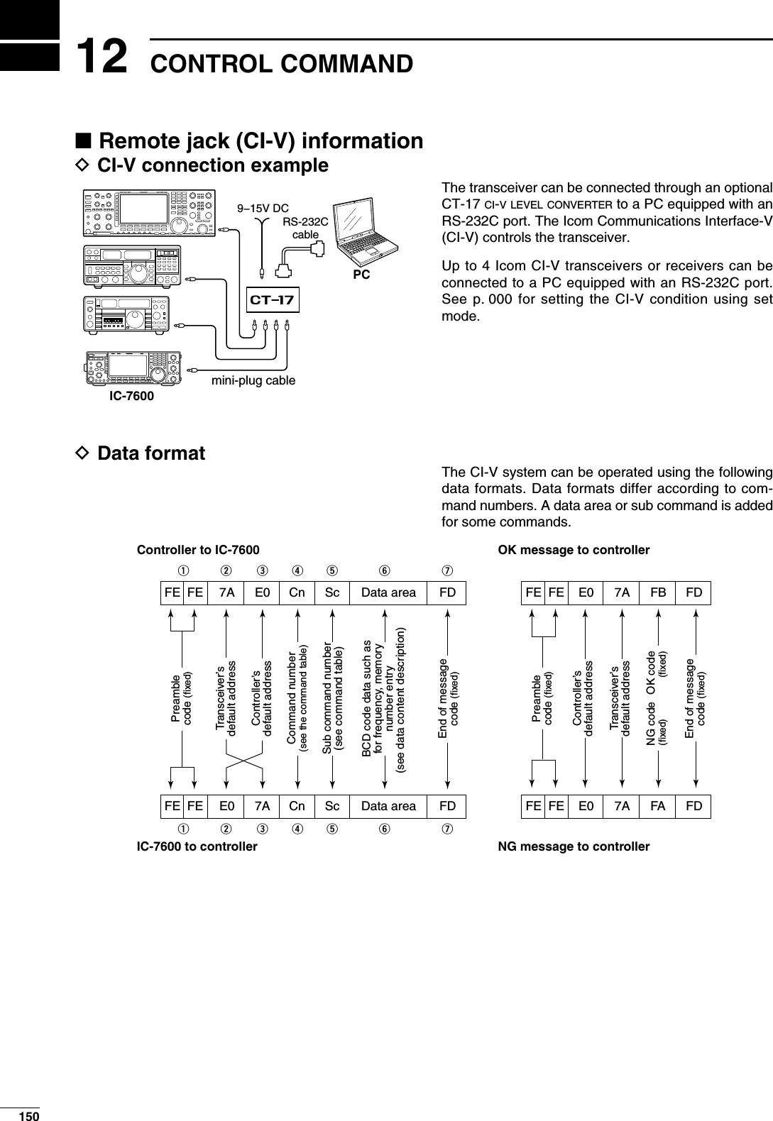
![D Command table15112CONTROL COMMAND123456789101112131415161718192021Cmd.Sub cmd.Data Description00 see p. 000 Send frequency data (transceive)01 00 Select LSB (transceive)01 Select USB (transceive)02 Select AM (transceive)03 Select CW (transceive)04 Select RTTY (transceive)05 Select FM (transceive)07 Select CW-R (transceive)08 Select RTTY-R (transceive)12 Select PSK (transceive)13 Select PSK-R (transceive)02 see p. 000 Read band edge frequencies03 see p. 000 Read operating frequency04 see p. 000 Read operating mode05 see p. 000 Set operating frequency06 00 Select LSB01 Select USB02 Select AM03 Select CW04 Select RTTY05 Select FM07 Select CW-R08 Select RTTY-R12 Select PSK13 Select PSK-R07 Select VFO modeB0 Exchange main and sub bandsB1 Equalize main and sub bandsC0 Turn the dualwatch OFFC1 Turn the dualwatch OND0 Select main bandD1 Select sub band08 Select memory mode0001 to 0099Select memory channel (0001=M-CH01, 0099=M-CH99)0100 Select program scan edge channel P10101 Select program scan edge channel P209 Memory write0A Copying memory contents into VFO0B Memory clear0E 00 Scan stop01 Programmed/memory scan start02 Programmed scan start03 :F scan start12 Fine programmed scan start13 Fine :F scan start22 Memory scan start23 Select memory scan startA1 Select :F scan span ±5 kHzA2 Select :F scan span ±10 kHzA3 Select :F scan span ±20 kHzA4 Select :F scan span ±50 kHzA5 Select :F scan span ±100 kHzA6 Select :F scan span ±500 kHzA7 Select :F scan span ±1 MHzB0 Set as non-select channelB1 Set as select channel ( The previously set number by CI-V is set after turning power ON, or “1” is selected if no selec-tion is performed.)01 Set as select channel “(1”02 Set as select channel “(2”03 Set as select channel “(3”B2 00 Set “ALL” for select memory scan01 Set “(1” for select memory scan02 Set “(2” for select memory scan03 Set “(3” for select memory scanD0 Set scan resume OFFD3 Set scan resume ON0F 00 Turn the split function OFF01 Turn the split function ONCmd.Sub cmd.Data Description10 00 Select 10 Hz (1 Hz) tuning step01 Select 100 Hz tuning step02 Select 1 kHz tuning step03 Select 5 kHz tuning step04 Select 9 kHz tuning step05 Select 10 kHz tuning step06 Select 12.5 kHz tuning step07 Select 20 kHz tuning step08 Select 25 kHz tuning step11 00 Send/read attenuator OFF06 Send/read 6 dB attenuator12 Send/read 12 dB attenuator18 Send/read 18 dB attenuator12 0000 Send/read ANT1 selection (RX ANT OFF)0001 Send/read ANT1 selection (RX ANT ON)0100 Send/read ANT2 selection (RX ANT OFF)0101 Send/read ANT2 selection (RX ANT ON)13 00 Announce all data with voice synthesizer01 Announce frequency and S-meter level with voice synthesizer02Announce receive mode with voice synthesizer14 01 0000 to 0255Send/read [AF] level (0000=max. CCW, 0255=max. CW)02 0000 to 0255Send/read [RF] level (0000=max. CCW, 0255=11 o'clock)03 0000 to 0255Send/read [SQL] level (0000=11 o'clock, 0255=max. CW)06 0000 to 0255Send/read [NR] level (0000=0%, 0255=100%)07 0000 to 0255Send/read inner [TWIN PBT] position (0000=max. CCW, 0128=center, 0255=max. CW)08 0000 to 0255Send/read outer [TWIN PBT] position (0000=max. CCW, 0128=center, 0255=max. CW)09 0000 to 0255Send/read CW pitch ( 0000=300 Hz, 0128=600 Hz, 0255=900 Hz; 5 Hz steps)0A 0000 to 0255Send/read [RF POWER] level (0000=max. CCW, 0255=max. CW)0B 0000 to 0255Send/read [MIC GAIN] level (0000=max. CCW, 0255=max. CW)0C 0000 to 0255Send/read [KEY SPEED] level (0000=max. CCW, 0255=max. CW)0D 0000 to 0255Send/read [NOTCH] position (0000=max. CCW, 0128=center, 0255=max. CW)0E 0000 to 0255Send/read COMP level(0000=0, 0255=10)0F 0000 to 0255Send/read [BK-IN DELAY] position (0000=max. CCW, 0255=max. CW)10 0000 to 0255Send/read [BAL] position (0000=max. CCW, 0128=center, 0255=max. CW)12 0000 to 0255Send/read NB level (0000=0%, 0255=100%)14 0000 to 0255Send/read DRIVE gain (0000=0%, 0255=100%)15 0000 to 0255Send/read Monitor gain (0000=0%, 0255=100%)16 0000 to 0255Send/read VOX gain (0000=0%, 0255=100%)17 0000 to 0255Send/read Anti VOX gain (0000=0%, 0255=100%)19 0000 to 0255Send/read BRIGHT level (0000=0%, 0255=100%)15 01 00 Read squelch condition (squelch close)01 Read squelch condition (squelch open)02 0000 to 0255Read S-meter level (0000=S0, 0120=S9, 0241=S9+60)11 0000 to 0255Read RF power meter (0000=0, 0143=50, 0213=100)12 0000 to 0255Read SWR meter (0000=SWR1.0, 0048=SWR1.5, 0080=SWR2.0)13 0000 to 0255Read ALC meter (0000=0, 0120=Max.)14 0000 to 0255Read COMP meter (0000=0, 0130=15, 0241=30)](https://usermanual.wiki/ICOM-orporated/307300.User-Manual-2/User-Guide-1066301-Page-69.png)
![D Command table (continued)Cmd.Sub cmd.Data Description15 15 0000 to 0255Read VD meter (0152=10, 0181=13, 0212=16)16 0000 to 0255Read ID meter (0000=0, 0097=10, 0241=25)16 02 00 Preamp OFF01 Preamp 1 ON02 Preamp 2 ON12 00 AGC FAST selection01 AGC MID selection02 AGC SLOW selection22 00 Noise blanker OFF01 Noise blanker ON32 00 Audio peak filter OFF01 Audio peak filter WIDE ON (320 is selected when SHARP APF is set)02 Audio peak filter MID ON (160 is selected when SHARP APF is set)03 Audio peak filter NAR ON (80 is selected when SHARP APF is set)40 00 Noise reduction OFF01 Noise reduction ON41 00 Auto notch function OFF01 Auto notch function ON42 00 Repeater tone OFF01 Repeater tone ON43 00 Tone squelch OFF01 Tone squelch ON44 00 Speech compressor OFF01 Speech compressor ON45 00 Monitor function OFF01 Monitor function ON46 00 VOX function OFF01 VOX function ON47 00 BK-IN function OFF01 SEMI BK-IN function ON02 Full BK-IN function ON48 00 Manual notch function OFF01 Manual notch function ON4F 00 Twin peak filter OFF01 Twin peak filter ON50 00 Dial lock function OFF01 Dial lock function ON19 00 Reads the transceiver ID1A 00 see p. 000 Send/read memory contents01 see p. 000 Send/read band stacking register contents02 see p. 000 Send/read memory keyer contents03 00 to 49 Send/read the selected filter width ( SSB, CW, PSK: 00=50 Hz, 40=3600 Hz; RTTY: 00=50 Hz, 31=2700 Hz; AM: 00=200 Hz, 49=10 kHz)04 00 to 13 Send/read the selected AGC time constant (00=OFF, 01=0.1/0.3 sec., 13=6.0/8.0 sec.)05 0001 see p. 000Send/read HPF/LPF setting for SSB RX audio0002 00 to 10 Send/read SSB RX Tone (Bass) level (00=–5, 10=+5)0003 00 to 10 Send/read SSB RX Tone (Treble) level (00=–5, 10=+5)0004 see p. 000 Send/read HPF/LPF setting for AM RX audio0005 00 to 10 Send/read AM RX tone (Bass) level (00=–5, 10=+5)0006 00 to 10 Send/read AM RX Tone (Treble) level (00=–5, 10=+5)0007 see p. 000 Send/read HPF/LPF setting for FM RX audio0008 00 to 10 Send/read FM RX tone (Bass) level (00=–5, 10=+5)0009 00 to 10 Send/read FM RX Tone (Treble) level (00=–5, 10=+5)0010 see p. 000 Send/read HPF/LPF setting for CW RX audio0011 see p. 000Send/read HPF/LPF setting for RTTY RX audio0012 see p. 000Send/read HPF/LPF setting for PSK RX audio0013 00 to 10 Send/read SSB TX Tone (Bass) level (00=–5, 10=+5)0014 00 to 10 Send/read SSB TX Tone (Treble) level (00=–5, 10=+5)Cmd.Sub cmd.Data Description1A 05 0015 00 to 10 Send/read AM TX Tone (Bass) level (00=–5, 10=+5)0016 00 to 10 Send/read AM TX Tone (Treble) level (00=–5, 10=+5)0017 00 to 10 Send/read FM TX Tone (Bass) level (00=–5, 10=+5)0018 00 to 10 Send/read FM TX Tone (Treble) level (00=–5, 10=+5)0019 see p. 000 Send/read SSB TX bandwidth for WIDE0020 see p. 000 Send/read SSB TX bandwidth for MID.0021 see p. 000 Send/read SSB TX bandwidth for NARROW0022 0000 to 0255Send/read DRIVE gain (0000=0%, 0255=100%)0023 0000 to 0255Send/read speech level (0000=0%, 0255=100%)0024 0000 to 0255Send/read CW side tone level (0000=0%, 0255=100%)0025 00 CW side tone gain limit OFF01 CW side tone gain limit ON0026 0000 to 0255Send/read beep gain (0000=0%, 0255=100%)0027 00 Beep gain limit OFF01 Beep gain limit ON0028 00 Squelch mute effect OFF for audio output from USB-B connector01 Squelch mute effect ON for audio output from USB-B connector0029 0000 to 0255Send/read modulation level for audio input to USB-B connector (0000=0%, 0255=100%)0030 00 [MIC] selection for MOD input connector dur-ing DATA OFF01 [ACC] selection for MOD input connector during DATA OFF02 Both [MIC] and [ACC] selection for MOD input connector during DATA OFF03 [USB] selection for MOD input connector dur-ing DATA OFF0031 00 [MIC] selection for MOD input connector dur-ing DATA101 [ACC] selection for MOD input connector during DATA102 Both [MIC] and [ACC] selection for MOD input connector during DATA103 [USB] selection for MOD input connector dur-ing DATA10032 00 [MIC] selection for MOD input connector dur-ing DATA201 [ACC] selection for MOD input connector during DATA202 Both [MIC] and [ACC] selection for MOD input connector during DATA203 [USB] selection for MOD input connector dur-ing DATA20033 00 [MIC] selection for MOD input connector dur-ing DATA301 [ACC] selection for MOD input connector during DATA302 Both [MIC] and [ACC] selection for MOD input connector during DATA303 [USB] selection for MOD input connector dur-ing DATA30034 00 Lead selection for SEND relay type01 MOS-FET selection for SEND relay type0035 00 Auto selection for external meter output01 S (receiving signal strength) selection for ex-ternal meter output02 Po (TX output power) selection for external meter selection03 SWR selection for external meter output04 ALC selection for external meter output05 COMP selection for external meter output06 Vd selection for external meter output07 Id selection for external meter output0036 0000 to 0255Send/read external meter output level (see p. 000)15212 CONTROL COMMAND](https://usermanual.wiki/ICOM-orporated/307300.User-Manual-2/User-Guide-1066301-Page-70.png)
![D Command table (continued)Cmd.Sub cmd.Data Description1A 05 0037 0000 to 0255Send/read reference frequency (0000=0%, 0255=100%)0038 0000 to 0255Send/read LCD backlight brightness level (00=0% (dark), 255=100% (bright))0039 0000 to 0255Send/read key backlight brightness level (00=0% (dark), 0255=100% (bright))0040 00 Display type A selection01 Display type B selection0041 00 Basic font selection01 Italic font selection02 Round font selection0042 00 SLOW selection for meter response01 MID selection for meter response02 FAST selection for meter response0043 00 Standard meter selection for normal screen indication01 Edgewise meter selection for normal screen indication02 Bar meter selection for normal screen indi-cation0044 00 Edgewise meter selection for wide screen in-dication01Bar meter selection for wide screen indication0045 00 Meter peak hold function for Bar meter OFF01 Meter peak hold function for Bar meter ON0046 00 Memory name indication OFF01 Memory name indication ON0047 00 Audio peak filter width pop-up indication OFF01 Audio peak filter width pop-up indication ON0048 00Manual notch filter width pop-up indication OFF01Manual notch filter width pop-up indication ON0049 00 Screen saver OFF01 15 min. selection for screen saver02 30 min. selection for screen saver03 60 min. selection for screen saver0050 00 Bound selection for screen saver type01 Round selection for screen saver type02 Twist selection for screen saver type0051 00 Opening screen indication OFF01 Opening screen indication ON0052 see p. 000 Send/read opening screen contents.0053 20000101 to 20991231Send/read date ( 20000101=1st Jan. 2000, 20991231=31st Dec. 2099)0054 0000 to 2359Send/read time (0000=00:00, 2359=23:59)0055 00 Clock 2 OFF01 Clock 2 ON0056 see p. 000 Send/read offset time for clock 20057 see p. 000 Send/read clock 2 name *Up to 3 characters0058 00 Calibration marker OFF01 Calibration marker ON0059 00 Confirmation beep OFF01 Confirmation beep ON0060 00 Band edge beep OFF01 Band edge beep ON02 Band edge beep with user setting ON03Band edge beep with user setting/TX limit ON0061 0050 to 0200Send/read beep audio frequency (0050=500 Hz, 0200=2000 Hz)0062 00 Auto selection for [RF/SQL]01 SQL selection for [RF/SQL]02 RF+SQL selection for [RF/SQL]0063 00 Quick dualwatch OFF01 Quick dualwatch ON0064 00 Quick split function OFF01 Quick split function ON0065 see p. 000 FM split offset frequency setting for HF0066 see p. 000 FM split offset frequency setting for 50 MHz0067 00 Split lock function OFF01 Split lock function ON0068 00 Tuner auto start OFF01 Tuner auto start ONCmd.Sub cmd.Data Description1A 05 0069 00 PTT tune OFF01 PTT tune ON0070 00 Antenna selection OFF01 Manual antenna selection02 Auto antenna selection0071 00 Transverter functions automatically01 Transverter function ON0072 see p. 000 Transverter offset frequency0073 00 1275 Hz selection for RTTY mark frequency01 1615 Hz selection for RTTY mark frequency02 2125 Hz selection for RTTY mark frequency0074 00 170 Hz selection for RTTY shift width01 200 Hz selection for RTTY shift width02 425 Hz selection for RTTY shift width0075 00 RTTY keying with normal polarity01 RTTY keying with reverse polarity0076 00 1000 Hz selection for PSK tone frequency01 1500 Hz selection for PSK tone frequency02 2000 Hz selection for PSK tone frequency0077 00 English selection for voice synthesizer speech language01 Japanese selection for voice synthesizer speech language0078 00 Speech speed slow01 Speech speed fast0079 00 S-meter level announcement OFF01 S-meter announcement ON0080 00 Operating mode announcement OFF01 Operating mode announcement ON0081 00 [SPEECH/LOCK] key function setting ( Push momentariliy=SPEECH, Push and hold=LOCK)01 [SPEECH/LOCK] key function setting ( Push momentariliy=LOCK, Push and hold=SPEECH)0082 00 Number of memo pad channels 501 Number of memo pad channels 100083 00 Auto TS for main dial OFF01 Auto TS for main dial ON with LOW02 Auto TS for main dial ON with HIGH0084 00LOW selection for microphone Up/Down speed01HIGH selection for microphone Up/Down speed0085 00 Quick RIT/:TX clear OFF01 Quick RIT/:TX clear ON0086 00 Auto notch selection for SSB operation01 Manual notch selection for SSB operation02Auto/Manual notch operation for SSB operation0087 00 Auto notch selection for AM operation01 Manual notch selection for AM operation02Auto/Manual notch operation for AM operation0088 00 SSB/CW synchronous tuning function OFF01 SSB/CW synchronous tuning function ON0089 00 LSB selection for CW normal side set01 USB selection for CW normal side set0090 00 SHARP selection for APF type01 SOFT selection for APF type0091 00 Voice memory transmission OFF with exter-nal keypad01 Voice memory transmission ON with exter-nal keypad0092 00 Memory keyer transmission OFF with exter-nal keypad01 Memory keyer transmission ON with exter-nal keypad0093 00 RTTY memory transmission OFF with exter-nal keypad01 RTTY memory transmission ON with exter-nal keypad0094 00 PSK memory transmission OFF with exter-nal keypad01 PSK memory transmission ON with exter-nal keypad15312CONTROL COMMAND123456789101112131415161718192021](https://usermanual.wiki/ICOM-orporated/307300.User-Manual-2/User-Guide-1066301-Page-71.png)
![D Command table (continued)Cmd.Sub cmd.Data Description1A 05 0095 00 Voice memory transmission OFF with [F1]–[F4] on the keyboard01 Voice memory transmission ON with [F1]–[F4] on the keyboard0096 00 Memory keyer transmission OFF with [F1]–[F4] on the keyboard01 Memory keyer transmission ON with [F1]–[F4] on the keyboard0097 00 CI-V transceive OFF01 CI-V transceive ON0098 00 CI-V selection for [USB-B] usage01 Decode selection for [USB-B] usage0099 00 300 bps selection for decode speed01 1200 bps selection for decode speed02 4800 bps selection for decode speed03 9600 bps selection for decode speed04 19200 bps selection for decode speed0100 00 English keyboard selection01 Japanese keyboard selection02 United Kingdom keyboard selection03 French keyboard selection04 French (Canadian) keyboard selection05 German keyboard selection06 Portuguese keyboard selection07 Portuguese (Brazilian) keyboard selection08 Spanish keyboard selection09 Spanish (Latin American) keyboard selection10 Italian keyboard selection0101 0010 to 0100Send/read keyboard repeat delay ( 0010=100 msec., 0100=1000 msec.; 50 msec. steps)0102 00 to 31 Send/read keyboard repeat speed (00=2.0 cps, 31=30.0 cps)0103 00 Scope indication during TX OFF01 Scope indication during TX ON0104 00 Scope max. hold function OFF01 Scope max. hold function ON0105 00Filter center selection for scope center frequency01 Carrier point center selection for scope cent-er frequency02 Carrier point center (Abs. Freq.) selection for scope center frequency0106 see p. 000Send/read waveform color for receiving signal0107 see p. 000 Send/read waveform color for max. hold0108 00 SLOW selection for scope sweep speed in ±2.5 kHz span01 MID selection for scope sweep speed in ±2.5 kHz span02 FAST selection for scope sweep speed in ±2.5 kHz span0109 00 SLOW selection for scope sweep speed in ±5 kHz span01 MID selection for scope sweep speed in ±5 kHz span02 FAST selection for scope sweep speed in ±5 kHz span0110 00 SLOW selection for scope sweep speed in ±10 kHz span01 MID selection for scope sweep speed in ±10 kHz span02 FAST selection for scope sweep speed in ±10 kHz span0111 00 SLOW selection for scope sweep speed in ±25 kHz span01 MID selection for scope sweep speed in ±25 kHz span02 FAST selection for scope sweep speed in ±25 kHz span0112 00 SLOW selection for scope sweep speed in ±50 kHz span01 MID selection for scope sweep speed in ±50 kHz span02 FAST selection for scope sweep speed in ±50 kHz spanCmd.Sub cmd.Data Description1A 05 0113 00 SLOW selection for scope sweep speed in ±100 kHz span01 MID selection for scope sweep speed in ±100 kHz span02 FAST selection for scope sweep speed in ±100 kHz span0114 00 SLOW selection for scope sweep speed in ±250 kHz span01 MID selection for scope sweep speed in ±250 kHz span02 FAST selection for scope sweep speed in ±250 kHz span0115 see p. 000 Scope edge frequencies for 0.03 to 1.60 MHz band0116 see p. 000 Scope edge frequencies for 1.60 MHz to 2.00 MHz band0117 see p. 000 Scope edge frequencies for 2.00 MHz to 6.00 MHz band0118 see p. 000 Scope edge frequencies for 6.00 MHz to 8.00 MHz band0119 see p. 000 Scope edge frequencies for 8.00 MHz to 11.00 MHz band0120 see p. 000 Scope edge frequencies for 11.00 MHz to 15.00 MHz band0121 see p. 000 Scope edge frequencies for 15.00 MHz to 20.00 MHz band0122 see p. 000 Scope edge frequencies for 20.00 MHz to 22.00 MHz band0123 see p. 000 Scope edge frequencies for 22.00 MHz to 26.00 MHz band0124 see p. 000 Scope edge frequencies for 26.00 MHz to 30.00 MHz band0125 see p. 000 Scope edge frequencies for 30.00 MHz to 45.00 MHz band0126 see p. 000 Scope edge frequencies for 45.00 MHz to 60.00 MHz band0127 00 Auto monitor function OFF during voice memory transmission01 Auto monitor function ON during voice mem-ory transmission0128 03 to 10 Send/read voice memory short play time (03=3 sec., 10=10 sec.)0129 05 to 15 Send/read voice memory normal record time (05=5 sec., 15=15 sec.)0130 00 Normal selection for contest number style01 “190¡ANO” selection for contest number style02 “190¡ANT” selection for contest number style03 “90¡NO” selection for contest number style04 “90¡NT” selection for contest number style0131 01 M1 selection for count up trigger channel02 M2 selection for count up trigger channel03 M3 selection for count up trigger channel04 M4 selection for count up trigger channel0132 0001 to 9999Send/read present number (0001=1, 9999=9999)0133 01 to 60 Send/read CW keyer repeat time (01=1 sec., 60=60 sec.)0134 28 to 45 Send/read CW keyer dot/dash ratio (28=1:1:2.8, 45=1:1:4.5)0135 00 2 msec. selection for rise time01 4 msec. selection for rise time02 6 msec. selection for rise time03 8 msec. selection for rise time04 10 msec. selection for rise time0136 00 Normal selection for paddle polarity01 Reverse selection for paddle polarity0137 00 Straight selection for keyer type01 BUG-KEY selection for keyer type02 ELEC-KEY selection for keyer type0138 00 Mic. up/down keyer function OFF01 Mic. up/down keyer function ON15412 CONTROL COMMAND](https://usermanual.wiki/ICOM-orporated/307300.User-Manual-2/User-Guide-1066301-Page-72.png)
![D Command table (continued) Cmd.Sub cmd.Data Description1A 05 0139 00 RTTY decoder FFT scope averaging func-tion OFF01 Number 2 selection for RTTY decoder FFT scope averaging function02 Number 3 selection for RTTY decoder FFT scope averaging function03 Number 4 selection for RTTY decoder FFT scope averaging function0140 see p. 000 Set/read FFT scope waveform color set for RTTY decoder0141 00 RTTY decode USOS function OFF01 RTTY decode USOS function ON0142 00 “CR,LF,CR+LF” selection for RTTY decode new line code01 “CR+LF” selection for RTTY decode new line code0143 00 OFF selection for RTTY diddle01 BLANK selection for RTTY diddle02 LTRS selection for RTTY diddle0144 00 RTTY encode USOS function OFF01 RTTY encode USOS function ON0145 00 RTTY auto CR+LF by keyboard’s [F12] OFF01 RTTY auto CR+LF by keyboard’s [F12] ON0146 00 RTTY time stamp OFF01 RTTY time stamp ON0147 00 Local time selection for RTTY time stamp01 Clock2 selection for RTTY time stamp0148 00 Frequency stamp for RTTY time stamp OFF01 Frequency stamp for RTTY time stamp ON0149 see p. 000 Send/read received text font color for RTTY decoder0150 see p. 000 Send/read transmitted text font color (RTTY)0151 see p. 000 Send/read time stamp text font color (RTTY)0152 see p. 000 Send/read text font color in TX buffer (RTTY)0153 00 PSK decoder FFT scope averaging func-tion OFF01 Number 2 selection for PSK decoder FFT scope averaging function02 Number 3 selection for PSK decoder FFT scope averaging function03 Number 4 selection for PSK decoder FFT scope averaging function0154 see p. 000 Set/read FFT scope waveform color set for PSK decoder0155 00 ±8 Hz selection for PSK AFC function tun-ing range01 ±15 Hz selection for PSK AFC function tun-ing range0156 00 PSK time stamp OFF01 PSK time stamp ON0157 00 Local time selection for PSK time stamp01 Clock2 selection for PSK time stamp0158 00 Frequency stamp for PSK time stamp OFF01 Frequency stamp for PSK time stamp ON0159 see p. 000 Send/read received text font color for PSK decoder0160 see p. 000 Send/read transmitted text font color (PSK)0161 see p. 000 Send/read time stamp text font color (PSK)0162 see p. 000 Send/read text font color in TX buffer (PSK)0163 00 LOW scan speed selection01 HIGH scan speed selection0164 00 Scan resume OFF01 Scan resume ON0165 0000 to 0255Send/read VOX gain (0000=0%, 0255=100%)0166 0000 to 0255Send/read ANTI-VOX gain (0000=0%, 0255=100%)0167 00 to 20 Send/read VOX delay time (00=0.0 sec., 20=2.0 sec.)0168 00 VOX voice delay function OFF01 Short selection for VOX voice delay02 Mid selection for VOX voice delay03 Long selection for VOX voice delayCmd.Sub cmd.Data Description1A 05 0169 0000 to 0255Send/read NB level (0000=0%, 0255=100%)0170 00 to 09 Send/read NB depth (00=1, 09=10)0171 0000 to 0255Send/read NB width (0000=1, 0255=100)0172 0000 to 0255Send/read MONITOR gain (0000=0%, 0255=100%)06 see p. 000 Send/read DATA mode with filter set07 00 WIDE selection for SSB transmit bandwidth01 MID selection for SSB transmit bandwidth02 NAR selection for SSB transmit bandwidth08 00 SHARP selection for DSP filter type01 SOFT selection for DSP filter type09 00 3 kHz roofing filter selection01 6 kHz roofing filter selection02 15 kHz roofing filter selection0A 00 WIDE selection for manual notch width01 MID selection for manual notch width02 NAR selection for manual notch width1B 00 see p. 000 Send/read repeater tone frequency01 see p. 000 Send/read tone squelch frequency1C 00 00 Transceiver's condition (RX)01 Transceiver's condition (TX)01 00 Antenna tuner OFF (through)01 Antenna tuner ON02 Tuning1E 00Read number of available TX frequency band01 see p. 000 Read TX band edge frequencies02 Read number of user-set TX frequency band03 see p. 000Send/read user-set TX band edge frequencies15512CONTROL COMMAND123456789101112131415161718192021](https://usermanual.wiki/ICOM-orporated/307300.User-Manual-2/User-Guide-1066301-Page-73.png)
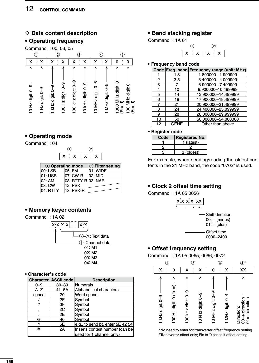
![• Codes for memory name, opening message and CLOCK2 name contentsTo send or read the desired memory name settings, the character codes, instructed codes for memory keyer contents, and follows are used. • Character’s code— Alphabetical charactersCharacter ASCII code Character ASCII codea–z 61–7A — —• Character’s code— Symbols Character ASCII code Character ASCII code!21#23$24%25&26¥ 5C?3F ” 22’27`60+2B– 2D:3A; 3B=3D< 3C>3E ( 28)29[ 5B]5D{ 7B}7D| 7C_5F– 7E@40• Color setting Command : 1A 05 0106, 0107, 0140, 0149, 0150, 0151, 0152, 0154, 0159, 0160, 0161, 01621000100101q0XXX0XXX0XXXwerty10001001011000100101R (Red) G (Green) B (Blue)Using 0000–0255 for each color element.• Bandscope edge frequency settingCommand : 1A 05 0115, 0116, 0117, 0118, 0119, 0120, 0121, 0122, 0123, 0124, 0125, 01261 kHz: 0–9100 Hz: 0 (fixed)100 kHz: 0–910 kHz: 0–910 MHz: 0–61 MHz: 0–91 kHz: 0–9100 Hz: 0 (fixed)100 kHz: 0–910 kHz: 0–910 MHz: 0–61 MHz: 0–9qXXXXXXXXXXXXwertyLower edge Higher edge• Data mode with filter width settingCommand : 1A 06qXX XXw00=Data mode OFF01=FIL102=FIL203=FIL300=Data mode OFF01=Data mode 1 (D1)02=Data mode 2 (D2)03=Data mode 3 (D3)• Repeater tone/tone squelch frequency settingCommand : 1B 00, 01100Hz digit: 0–210 Hz digit: 0–91 Hz digit: 0–90.1 Hz digit: 0–9Fixed digit: 0*Fixed digit: 0*q*00XXXweX*Not necessary when setting a frequency.• Band edge frequency settingCommand 02, 1E 01, 03qXXXwertyuio!0 !1 !2XXXXXXXXX2DXXXXXXXXXX10 Hz digit: 0–91 Hz digit: 0–91 kHz digit: 0–9100 Hz digit: 0–9100 kHz digit: 0–910 kHz digit: 0–910 MHz digit: 0–61 MHz digit: 0–91000 MHz digit: 0 (fixed)100 MHz digit: 0 (fixed)10 Hz digit: 0–91 Hz digit: 0–91 kHz digit: 0–9100 Hz digit: 0–9100 kHz digit: 0–910 kHz digit: 0–910 MHz digit: 0–61 MHz digit: 0–91000 MHz digit: 0 (fixed)100 MHz digit: 0 (fixed)Separater (fixed)Lower edge Higher edgeEdge numger: 00–3015712CONTROL COMMAND123456789101112131415161718192021](https://usermanual.wiki/ICOM-orporated/307300.User-Manual-2/User-Guide-1066301-Page-75.png)
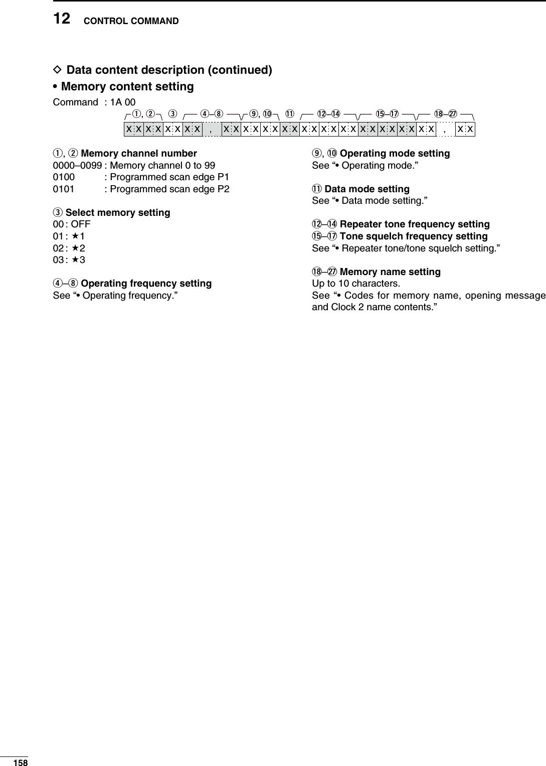
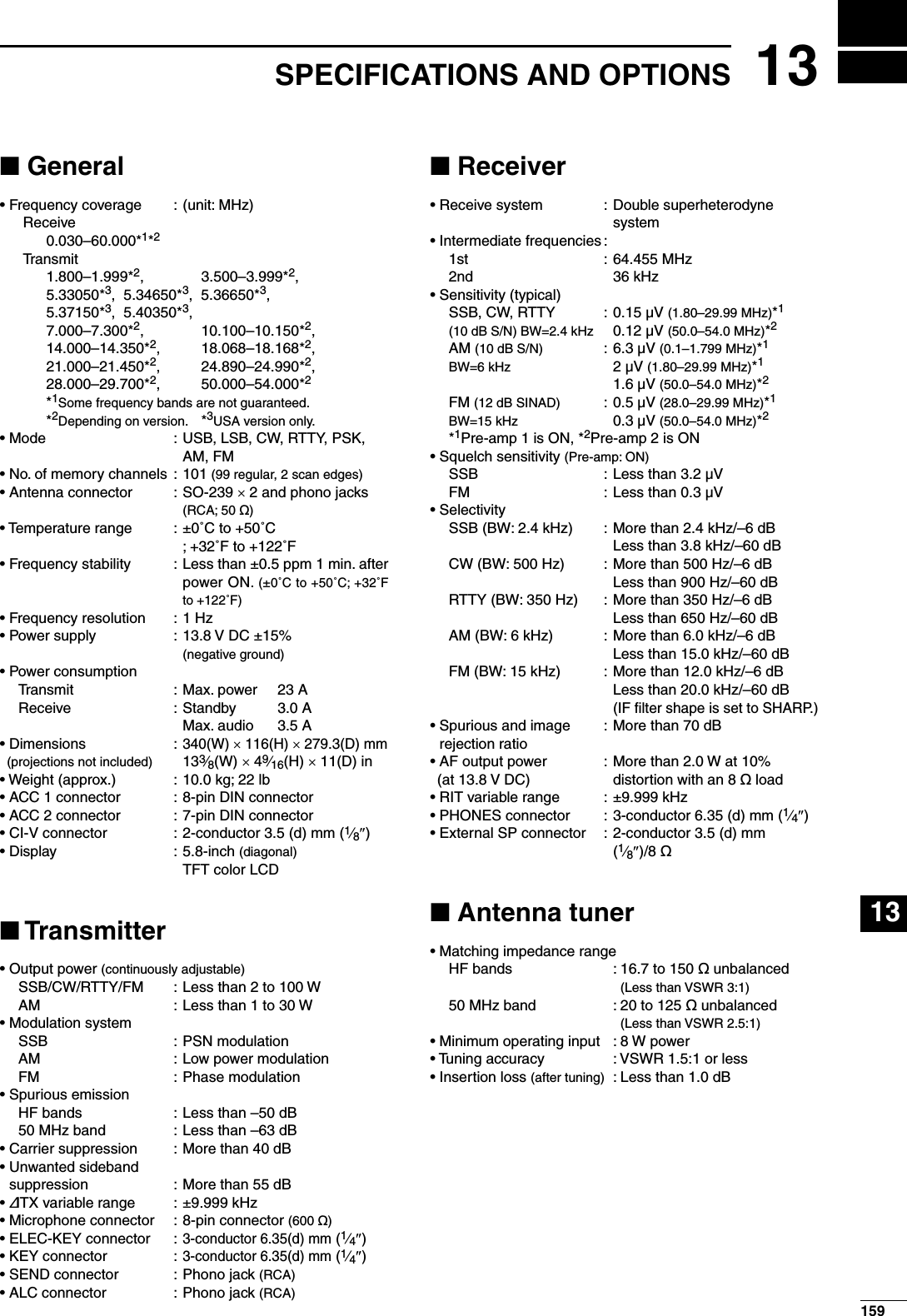
![AH-4 HF AUTOMATIC ANTENNA TUNERSpecially designed to tune a long wire antenna for portable or mobile HF/50 MHz operation. The “PTT tune” func-tion provides simple operation.• Input power rating: 150 WAH-2b ANTENNA ELEMENTA 2.5 m long antenna ele-ment for mobile operation with the AH-4.• Frequency coverage 7–54 MHz band with the AH-4SM-20 DESKTOP MICROPHONEIncludes [UP]/[DOWN] switches and a low cut function.SM-50 DESKTOP MICROPHONEIncludes [UP]/[DOWN] switches and a low cut function.SP-23 EXTERNAL SPEAKER4 audio filters; headphone jack; can connect to 2 transceivers.• Input impedance: 8 ø• Max. input power: 4 WHM-36 HAND MICROPHONEHand microphone equipped with [UP]/[DOWN] switches.CT-17 CI-V LEVEL CONVERTER UNITFor remote transceiver control using a personal computer equipped with an RS-232C port. You can change fre-quencies, operating mode, memory channels, etc., via your computer.MB-121 CARRYING HANDLEConvenient when carrying the trans-ceiver.IC-PW1/EURO HF/50 MHz ALL BAND 1 kW LINEAR AMPLIFIERFull-duty 1 kW linear amplifier including an automatic antenna tuner. Has auto-matic tuning and band selection capability. Full break-in (QSK) operation is pos-sible. The amplifier/power supply unit and the remote control unit are separated. An optional OPC-599 is required for connection.PS-126 DC POWER SUPPLY• Output voltage : 13.8 V DC• Max. output current : 25 A16013 SPECIFICATIONS AND OPTIONS](https://usermanual.wiki/ICOM-orporated/307300.User-Manual-2/User-Guide-1066301-Page-78.png)
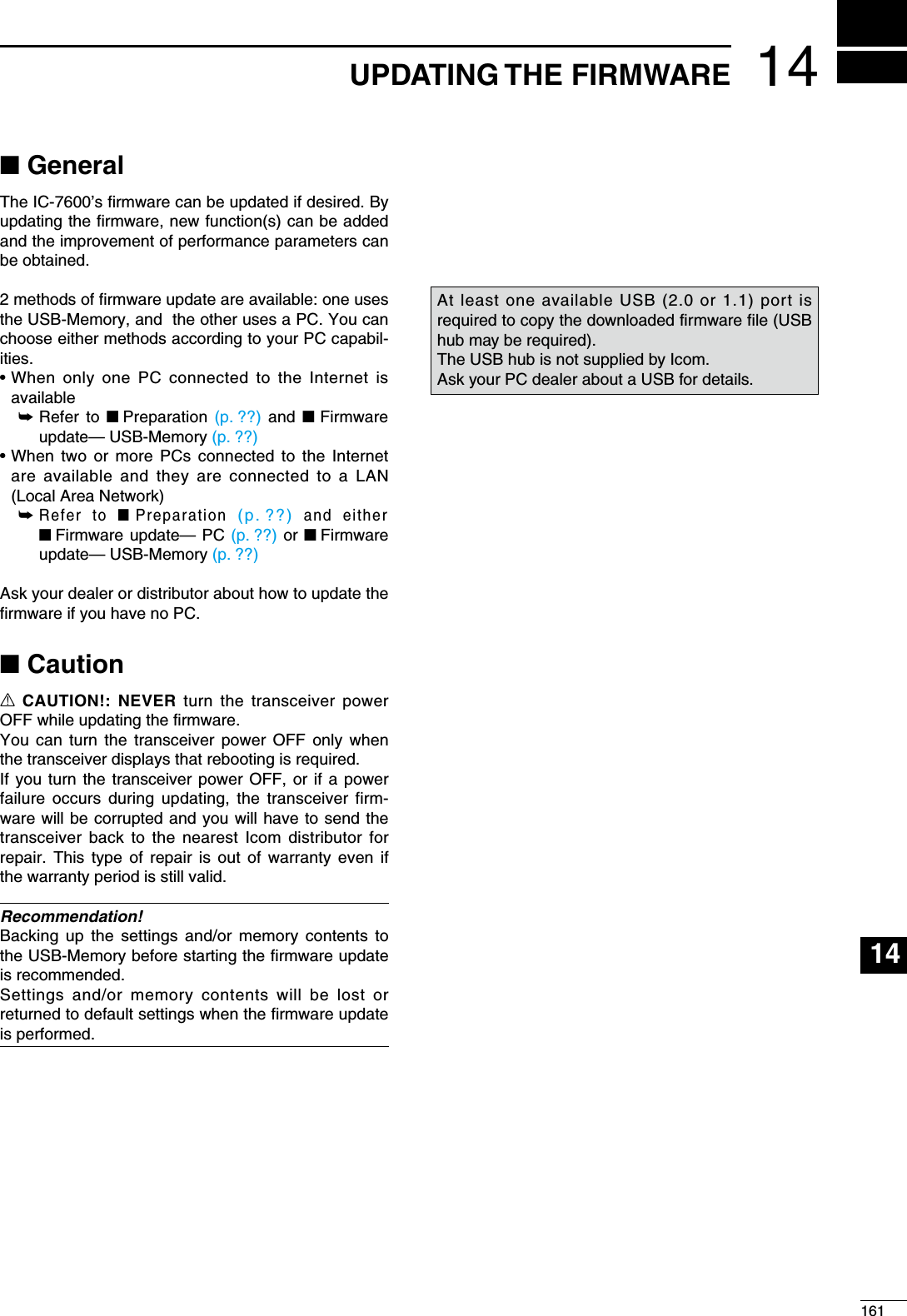
![N PreparationD Firmware and firm utilityThe latest firmware and the firm utility can be down-loaded from the Icom home page via the Internet. Access the following URL to download the firm utility and the latest firmware. http://www.icom.co.jp/world/support/index.htmlFor updating from the USB-MemoryWhen updating the firmware from the USB-Memory, copy the downloaded firmware data (e.g. 7600_110.dat) to the USB-Memory (in “IC-7600” folder) using an available USB port (USB hub may be required; pur-chased separately from your PC dealer).D File downloadingq Access the following URL directly. http://www.icom.co.jp/world/support/index.htmlw Click “Firmware Updates/Software Downloads” link then click the firmware file link.e Read “Regarding this Download Service” carefully, then click [AGREE].r Click [Save] in the displayed File Download dialog.t Select the desired location in which you want to save the firmware, then click [Save] in the dis-played File Download dialog. • File download starts.y After download is completed, extract the file. • The firmware and the firm utility are compressed in “zip” format, respectively. • When updating the transceiver using with the USB-Memory, copy the extracted firmware (e.g. 7600_110.dat) to the USB-Memory IC-7600 folder. • The USB-Memory must have been formatted by the IC-7600. (p. ??)ClickRead carefullyhttp://www.icom.co.jp/world/support/download/firm/IC-7600/1_10/index.htmlClickSelect the savinglocationClick7600_110.dat16214 UPDATING THE FIRMWARE](https://usermanual.wiki/ICOM-orporated/307300.User-Manual-2/User-Guide-1066301-Page-80.png)
![16314UPDATING THE FIRMWARE123456789101112131415161718192021q Copy the downloaded firmware data into the USB-Memory (“IC-7600” folder). • The USB-Memory must have been formatted by the IC-7600.w Insert the USB-Memory into the USB connector.e Push [EXIT/SET] several times to close a multi-function screen, if necessary.r Push [SET] (F-6) to select set mode menu screen.t Push [USB] (F-6) to select USB-Memory set menu.y Push and hold [FIRM UP] (F-3) for 1 sec.u Read the displayed precaution carefully. • Push [Y] (F-1) or [Z] (F-2) to scroll the indication. • Push [CANCEL] (F-6) to cancel the firmware updating.i After you read and understand all of the precau-tions, push [OK] (F-5). • [OK] (F-5) appears only following the precautions. • Push [CANCEL] (F-6) to cancel the firmware updating.o Push [Y] (F-2) or [Z] (F-3) to select the firmware file, then push [FIRM UP] (F-4).!0 Read the displayed precautions carefully.!1 If you agree, push and hold [OK] (F-5) for 1 sec. to start the firmware update. • Push [CANCEL] (F-7) to cancel the firmware updating.!2 While loading the firmware from the USB-Memory, the dialog as at left is displayed.F-1 F-2F-5 F-6EXIT/SETUSBSET CANCELDIR/FILEOKF-4FIRM UPF-3FIRM UP /////N Firmware update— USB-Memory](https://usermanual.wiki/ICOM-orporated/307300.User-Manual-2/User-Guide-1066301-Page-81.png)
![!3 After the firmware loading is completed, the trans-ceiver starts the update automatically and the dia-log at left is displayed.RWARNING!: NEVER turn the IC-7600 power OFF at this stage.The transceiver firmware will be corrupted.!4 When the dialog disappears, the precaution at left is displayed.!5 Read the precaution carefully, and then push [OK] (F-5). • Return to USB-Memory set menu.!6 Push [POWER] to turn the IC-7600 power OFF, then ON again.!7 Depending on the update, one or two dialog boxes as at left appear in sequence.RWARNING!: NEVER turn the IC-7600 power OFF at this stage. The transceiver firmware will be corrupted.!8 After the dialog disappears, the firmware updat-ing is completed and normal operation screen appears. 25sec.10sec.TRX–DSP UPDATING... SCOPE–DSP UPDATING... Please wait for 10sec.WARING! NEVER turn power OFF.Please wait for 25sec.WARING! NEVER turn power OFF.16414 UPDATING THE FIRMWARE](https://usermanual.wiki/ICOM-orporated/307300.User-Manual-2/User-Guide-1066301-Page-82.png)