ICOM orporated 307400 VHF Air Band Transceiver User Manual IC A14 S Instruction Manual
ICOM Incorporated VHF Air Band Transceiver IC A14 S Instruction Manual
UserManual.wiki
>
ICOM orporated
>
307400 User Manual
>
User manual
Contents
1.
Manual
2.
Revised User Manual
3.
User manual
User manual
Navigation menu
Upload a User Manual
Namespaces
Wiki Guide
HTML
PDF
Info
Views
User Manual
Discussion / Help
Navigation
![■Panel descriptionq ANTENNA CONNECTOR [ANT] (p. 6)Connects to the supplied antenna.w KEY LOCK SWITCH [ ] (p. 9)➥ Push to turn ON the key lock function.➥ Hold down for 2 seconds to turn OFF the key lock func-tion.e LIGHT SWITCH [LIGHT] Push to toggle the LCD backlight ON or OFF. (p. 11) For the IC-A14S onlyIn the memory mode, hold down for 2 seconds to turn the “TAG” setting ON or OFF. (p. 20)r PTT SWITCH [PTT] Hold down to transmit, release to receive.t SQUELCH UP/DOWN KEYS [SQLY]/ [SQLZ] (p. 9)Push either key to select the squelch level. • 10 squelch levels, 1–10, and squelch open, 0, are selectable.y UP/DOWN KEYS [Y]/[Z] ➥ Push to change or select the operating frequency, memory channel, Set mode setting, and so on. (p. 8)➥ While scanning, push to change the scanning direction. (pp. 18, 19) For the IC-A14S onlyHold down for 1 second to start scanning. (pp. 18, 19)11PANEL DESCRIPTIONqwre!0Functiondisplay (p. 5)oiuMicrophoneSpeaker!1ty](https://usermanual.wiki/ICOM-orporated/307400.User-manual/User-Guide-3384207-Page-6.png)
![2u KEYPAD (Available with only the IC-A14) (pp. 3, 4)i MEMORY MODE/MEMORY WRITE KEY [MR]/[MW]Push to select the memory mode. (p. 12) For the IC-A14➥ Push [FUNC], then push this key to enter the select memory write mode. (p. 13)➥ In the memory mode, push [FUNC] then push this key to copy the memory content to the frequency mode. (p. 16) For the IC-A14S➥ Hold down for 1 second to enter the select memory write mode. (p. 14)➥ In the memory mode, hold down for 1 second to copy the memory content to the frequency mode. (p. 16)o CLEAR/HOME SWITCH [CLR]/[HOME]➥ Push to select the frequency mode. (p. 8)➥ Hold down for 2 seconds to reset the transceiver to the user-default state without changing the memory con-tents (Home function). (p. 21)!0 EXTERNAL SPEAKER AND MICROPHONE JACKS [MIC/SP] (p. 39)If desired, connects the optional speaker microphone or a headset using the optional OPC-499 HEADSET ADAPTER.NEVER connect an optional speaker-microphone, headset adapter, while the transceiver power is ON.!1 VOLUME CONTROL KNOB [VOL]Rotate to turn the transceiver power ON or OFF and ad-just the audio level.1PANEL DESCRIPTIONJack coverNOTE: Attach the jack cover when optional equipment is not used.12345678910111213141516171819](https://usermanual.wiki/ICOM-orporated/307400.User-manual/User-Guide-3384207-Page-7.png)
![31PANEL DESCRIPTIOND KEYPAD (Available with IC-A14 only) ➥ Inputs digit “1” for frequency entry or memory channel selection. (pp. 8, 12) ➥ Inputs “1,” “Q,” or “Z” when entering memory names. (p. 15) ➥ After pushing [FUNC], turns the ANL (Automatic Noise Limiter) function ON or OFF. (p. 22) ➥ Inputs digit “2” for frequency entry or memory channel selection. (pp. 8, 12) ➥ Inputs “2,” “A,” “B,” or “C” when entering memory names. (p. 15) ➥ After pushing [FUNC], the scan starts. (pp. 18, 19) ➥ Inputs digit “3” for frequency entry or memory channel selection. (pp. 8, 12) ➥ Inputs “3,” “D,” “E,” or “F” when entering memory names. (p. 15) ➥ After pushing [FUNC], selects memory bank mode, in the memory mode. (p. 12) ➥ Inputs digit “4” for frequency entry or memory channel selection. (pp. 8, 12) ➥ Inputs “4,” “G,” “H,” or “I” when entering memory names. (p. 15) ➥ After pushing [FUNC], turns the weather alert function ON or OFF. (p. 23) ➥ Inputs digit “5” for frequency entry or memory channel selection. (pp. 8, 12) ➥ Inputs “5,” “J,” “K,” or “L” when entering memory names. (p. 15) ➥ After pushing [FUNC], enters duplex transmit fre-quency entry mode during NAVI band operation. (p. 24) ➥ Inputs digit “6” for frequency entry or memory channel selection. (pp. 8, 12) ➥ Inputs “6,” “M,” “N,” or “O” when entering memory names. (p. 15) ➥ After pushing [FUNC], selects duplex operation during NAVI band operation. (p. 24) ➥ Inputs digit “7” for frequency entry or memory channel selection. (pp. 8, 12) ➥ Inputs “7,” “P,” “R,” or “S” when entering memory names. (p. 15) ➥ After pushing [FUNC], selects weather channel mode. (p. 23) ➥ Inputs digit “8” for frequency entry or memory channel selection. (pp. 8, 12) ➥ Inputs “8,” “T,” “U,” or “V” when entering memory names. (p. 15) ➥ After pushing [FUNC], key touch beep output ON or OFF. (p. 22)](https://usermanual.wiki/ICOM-orporated/307400.User-manual/User-Guide-3384207-Page-8.png)
![41PANEL DESCRIPTION ➥ Inputs digit “9” for frequency entry or memory channel selection. (pp. 8, 12) ➥ Inputs “9,” “W,” “X,” or “Y” when entering memory names. (p. 15) ➥ After pushing [FUNC], toggles scan tag setting ON or OFF. (p. 20) ➥ Inputs digit “0” for frequency entry or memory channel selection. (pp. 8, 12) ➥ Inputs “0,” “space” or “–” when entering memory names. (p. 15) ➥ After pushing [FUNC], selects the emergency fre-quency, 121.500 MHz. (p. 21) ➥ Sets the numeral entry for frequency or memory channel numbers. Enters consecutive zero into the remaining digits. (pp. 8, 12) ➥ After pushing [FUNC], hold down for 1 second to entering into set mode. (p. 25) ➥ Push to activate the function, then push another key to access its secondary function. When the function is activated, the “F” icon appears.12345678910111213141516171819](https://usermanual.wiki/ICOM-orporated/307400.User-manual/User-Guide-3384207-Page-9.png)
![51PANEL DESCRIPTION ■Function displayq FUNCTION ICONAppears when [FUNC] is pushed.w MEMORY ICON (p. 12)Appears when memory channel mode is selected.e TAG ICON (p. 20)Appears when the selected memory channel is set as a TAG channel.r RX ICON (p. 10)Appears while receiving a signal, or when the squelch is open.t TX ICON (p. 10)Appears while transmitting.y DUPLEX ICON (IC-A14 only) (p. 24) ➥Appears when the duplex function is activated. ➥Blinks while setting the duplex frequency.u ANL ICON (p. 22)Appears when the ANL (Automatic Noise Limiter) func-tion is in use.i WEATHER ALERT ICON (IC-A14 only) (p. 23)Appears when the weather alert function is in use.o LOCK ICON (p. 9)Appears when the lock function is in use.!0 LOW BATTERY ICON (p. 11) ➥ Appears when the battery is nearing exhaustion. The attached battery pack requires recharging when this icon appears. ➥ Blinks when battery recharging/replacing is immedi-ately needed.!1 FREQUENCY READOUT Displays the operating frequency, memory channel num-ber, memory name or the Set mode item, and so on, de-pending on the selected mode.qwer tyuio!1!0](https://usermanual.wiki/ICOM-orporated/307400.User-manual/User-Guide-3384207-Page-10.png)
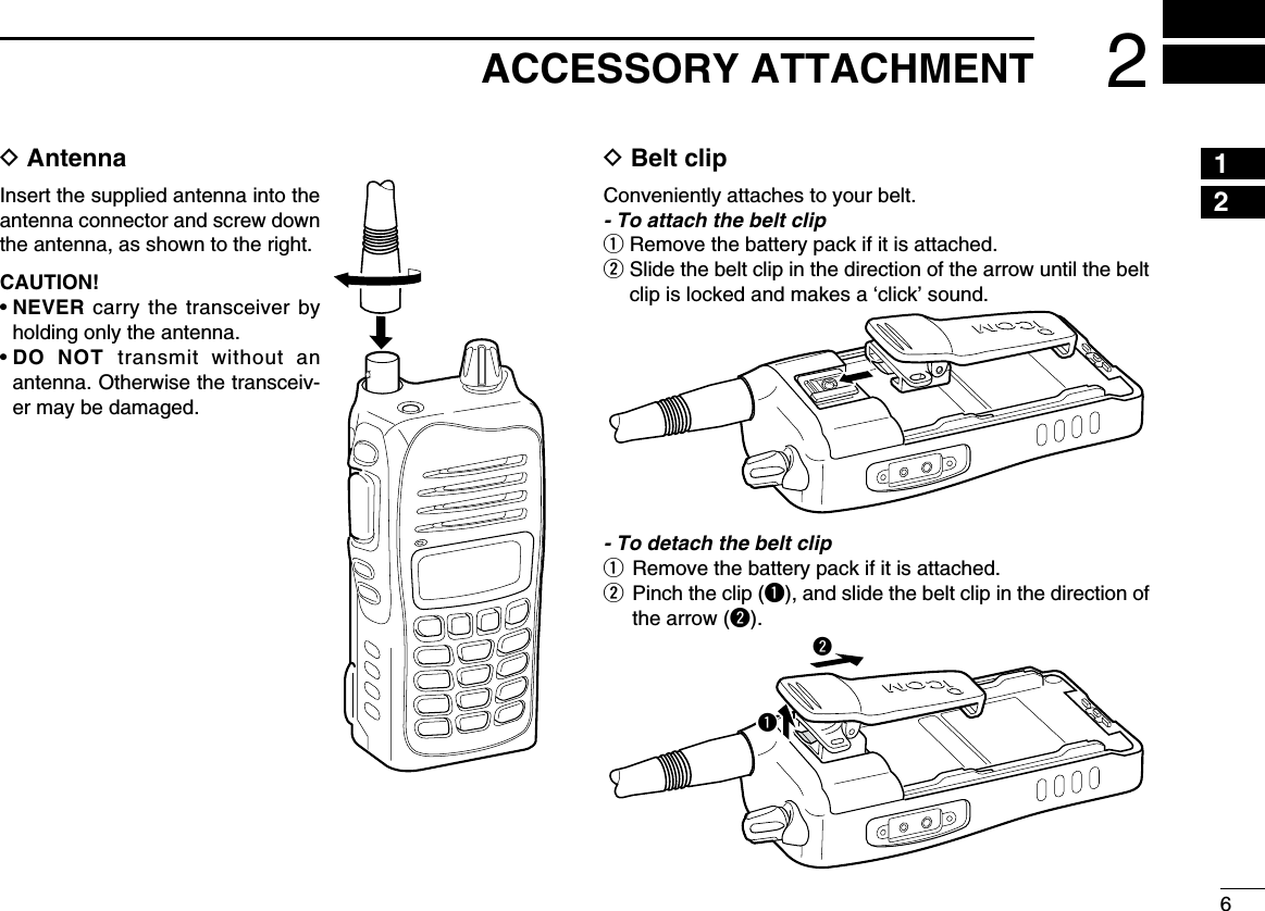
![7D Battery pack attachmentTo attach the battery pack:Slide the battery pack in the direction of the arrow (q), then lock it with the battery release button.• Slide the battery pack until the battery release button makes a ‘click’ sound.To detach the battery pack:Slide the battery release button in the direction of the arrow (w) as shown in the illustration to the right. The battery pack can then be detached.NEVER release or attach the battery pack when the trans-ceiver is wet or soiled. This may result water or dust get-ting into the transceiver/battery pack and may result in the transceiver being damaged.2ACCESSORY ATTACHMENTqwBattery release buttonTurn OFF the transceiver power by rotating [VOL] before at-taching or detaching the battery pack.For your informationIf the transceiver power cannot be turned ON after replacing the fully charged battery pack, first detach the battery pack.Wait for approximately 10 seconds, then attach the battery pack and turn ON the power again.](https://usermanual.wiki/ICOM-orporated/307400.User-manual/User-Guide-3384207-Page-12.png)
![83BASIC OPERATION ■Setting a frequencyD Using the [Y]/[Z] keysq Rotate [VOL] to turn ON power, then push [CLR] to select the frequency mode if a memory CH number or WX CH number appears on the function display.w Push [Y]/[Z] to set the desired frequency. - For the IC-A14 only - • The 1 MHz tuning step is selectable. Push [FUNC], then push [Y]/[Z]. Push [FUNC] again to return to normal tuning.D Using keypad (IC-A14 only)q Rotate [VOL] to turn ON power, then push [CLR] to select the frequency mode if a memory CH number or WX CH number appears on the function display.w Push 5 appropriate digit keys to input the frequency. • Push [1] as the 1st digit. • When a wrong digit is input, push [CLR] to clear, then repeat step w again. • Push [ENT] to enter consecutive zero digits. • Only [2], [5], [7] or [0] can be entered as the 5th and final digit. [EXAMPLE] • 111.225 MHz: Push [1], [1], [1], [2], [2] • 117.250 MHz: Push [1], [1], [7], [2], [5] • 120.000 MHz: Push [1], [2], [ENT] • 125.300 MHz: Push [1], [2], [5], [3], [ENT]23[VOL][FUNC][Z][ENT][CLR][Y]Keypad145678910111213141516171819](https://usermanual.wiki/ICOM-orporated/307400.User-manual/User-Guide-3384207-Page-13.png)
![■Setting the squelch levelThe transceiver has a noise squelch circuit to mute undesired noise when no signal is received.q Push [SQLY] or [SQLZ] to select the squelch level. • ‘SQL--0’ is open squelch and ‘SQL--10’ is tight squelch. • The “ ” icon appears while the squelch is open.w Wait for 1 second to return to the previous display. ■Lock functionThe lock function prevents accidental frequency changes or accidental function activation.q Push [] to turn ON the lock function. • The “ ” icon appears.w To turn OFF the function, hold down [ ] for 2 seconds. • The “ ” icon disappears.93BASIC OPERATION[SQLY]“SQL-- 0” (Squelch open)[SQLZ][ ]Appears while the key lockfunction is activated.](https://usermanual.wiki/ICOM-orporated/307400.User-manual/User-Guide-3384207-Page-14.png)
![103BASIC OPERATION3 ■Receivingq Rotate [VOL] to turn ON the power.w Push [SQLZ] several times to open the squelch. • Select the squelch level 0.e Rotate [VOL] to adjust the audio level.r Push [SQLY] several times until the noise is muted. • The “ ” icon disappears.t Set the desired frequency using [Y]/[Z] keys or the key-pad keys.y When a signal is received on the set frequency: • The “ ” icon appears. • Squelch opens and audio is emitted from the speaker.When the squelch setting is too “tight” (large number setting), squelch may not open for weak signals. To receive weaker signals, loosen (small number setting) the squelch. ■Transmittingq Set the desired frequency in COM band pushing [Y]/[Z] or the keypad keys (IC-A14 only). • COM band frequency range: 118.00–136.975 MHzw Hold down [PTT] to transmit. • The “ ” icon appears.e Speak into the microphone at a normal voice level. • DO NOT hold the transceiver too close to your mouth or speak too loudly. This may distort the signal.r Release [PTT] to receive. NOTE: About Time-Out-Timer functionTo prevent prolonged transmission, according to regula-tory requirements, the IC-A14/S has a Time-Out Timer function. This timer cuts OFF transmission after the set time period of continuous transmission.The Time-Out Timer is set in the Set mode. See page 26 for details.CAUTION: Transmitting without an antenna may damage the transceiver.NOTE: To prevent interference, listen on the frequency before transmitting. If the frequency is busy, wait until it is clear.[PTT]MicrophoneAppears while transmittingAppears when a signal is received.1245678910111213141516171819](https://usermanual.wiki/ICOM-orporated/307400.User-manual/User-Guide-3384207-Page-15.png)
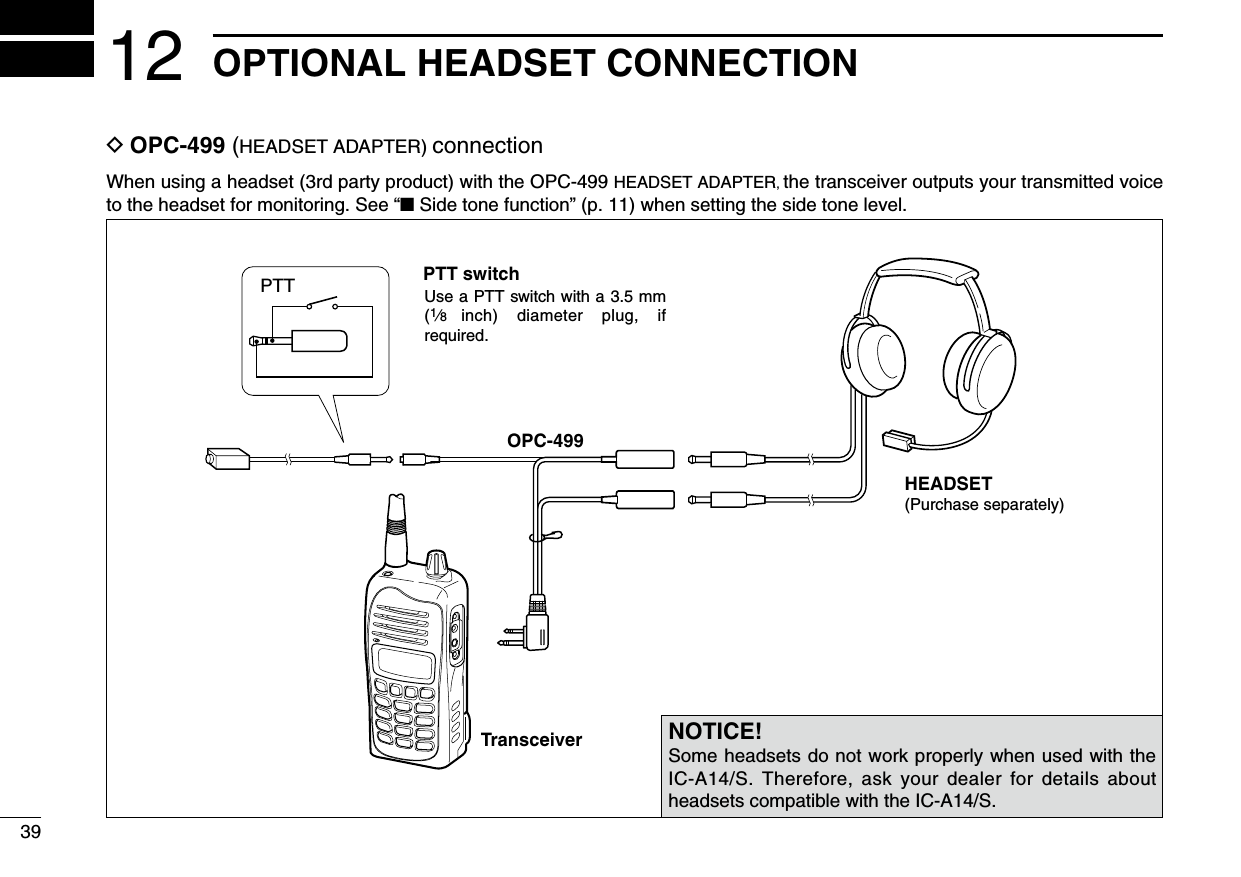
![113BASIC OPERATION ■Side tone functionWhen using a headset (user supplied), the transceiver outputs your transmitted voice to the headset for monitoring. Connect an optional headset to use this function (The OPC-499 headset adapter and headset are required). (p. 39)D Setting the side tone levelq Push [PTT] to turn ON the transmit mode.w While transmitting, push [Y]/[Z] to adjust the level. • ‘ST--0’ is OFF and ‘ST--10’ is the maximum level. WARNING! NEVER operate the transceiver with a head-set at high volume or monitor levels for a long periods time. If a ringing in your ears occurs, reduce the volume or monitor level, or discontinue use. ■LCD backlightThe IC-A14/S has an LCD backlight for convenience during night time operation.➥ Push [LIGHT] to turn the LCD backlight ON or OFF. IMPORTANT! Turn OFF the LCD back-light when no backlight is necessary. ■Low battery iconThe low battery icon appears or blinks when the battery power has decreased to a specified level. The attached bat-tery pack or battery case requires recharging or the battery case cells need replacing.If the batteries are not charging or replaced, even when the low battery indicator blinks, a long beep sounds and then the transceiver will automatically turn OFF.[PTT][Z]/[Y]Side tone level is indicatedIMPORTANT!Select ‘ST--0’ when a speaker microphone is connected, oth-erwise your voice will be heard from the speaker during trans-mit.[LIGHT]Appears when the battery is nearly exhausted.Blinks when the battery recharging or replacing isimmediately necessary.](https://usermanual.wiki/ICOM-orporated/307400.User-manual/User-Guide-3384207-Page-16.png)
![124MEMORY OPERATION ■Memory channel selectionThe IC-A14 has 200 memory channels (20 channels in 10 banks, default setting) and the IC-A14S has 100 memory chan-nels for storing often-used frequencies.q Push [MR] to enter the memory mode. • The memory mode icon appears and a memory channel num-ber is briefly displayed . • The memory bank number is also displayed on the IC-A14.Using [Y]/[Z]:w Push [Y]/[Z] to select the desired memory CH number. • The memory channel number is briefly displayed, then the entered frequency (or memory name, if entered) is displayed. • If no memory channel is entered, no memory channel can be selected.Using the Keypad— IC-A14 only:w Push 2 appropriate digit key (00 to 99, depending on the bank setting) to select the desired memory channel num-ber, then push [ENT]. • The memory channel number is briefly displayed, then the entered frequency (or memory name, if entered) is displayed. • If no memory channel is entered in the selected BANK, no memory channel can be selected. ■ Memory bank selection (Available with the IC-A14 only)A total of 200 memory channels in the IC-A14, are divided into bank (up to 10 banks are selectable, depending on the setting) for simple memory grouping.q Push [MR] to select the memory mode.w Push [FUNC], and push [BANK](3) to enter the bank se-lection mode.e Push [Y]/[Z] or an appropriate digit key ([0] to [9]) to select a memory BANK number, then push [ENT].r Push [Y]/[Z], or 2 appropriate digit keys and then [ENT] to select a memory channel.Appears when the memory mode is selected.Appears when the bank selection mode is selected.Keypad[FUNC][Z][ENT][BANK](3)[MR][Y]12345678910111213141516171819](https://usermanual.wiki/ICOM-orporated/307400.User-manual/User-Guide-3384207-Page-17.png)
![■Entering a memory channelEnter often-used frequencies using the following instructions.D For the IC-A14q Push [CLR] to select the frequency mode, if necessary.w Set the desired frequency. (p. 8) • Push [FUNC], then push [WX](7) to select a weather channel mode, and then select the desired weather channel using [Y]/[Z] or keypad if desired. (p. 23)e Push [FUNC], then push [MW](MR) to enter the select memory write mode. • The memory mode icon blinks.r Push [Y]/[Z] to select a memory channel number. • Push [FUNC], then push [BANK](3) to enter the bank selection mode, and push [Y]/[Z] or an appropriate digit keys ([0]–[9]), then push [ENT] to select the BANK number, if desired. t Push [ENT] to program the entry and return to the fre-quency mode.134MEMORY OPERATION• EXAMPLE: Entering WX-05 into memory channel 9 in memory BANK 3.Blinks when the select memory write mode is selected.No frequency is displayed when a blank channel is selected.PushPush thenPush thenPush then Push or ,or, pushPush or ,or, pushPush then*Briefly appears.Push to complete the entry.*Briefly appears.](https://usermanual.wiki/ICOM-orporated/307400.User-manual/User-Guide-3384207-Page-18.png)
![144MEMORY OPERATIOND For the IC-A14Sq Push [CLR] to select the frequency mode, if necessary.w Set the desired frequency. (p. 8)e Hold down [MR] for 1 second to enter the select memory write mode. • The memory mode icon blinks.r Push [Y]/[Z] to select the desired memory channel num-ber.t Hold down [MR] for 1 second to set the entry and return to the frequency mode.Blinks when the select memory write mode is selected.No frequency is displayed when a blank channel is selected.• EXAMPLE: Entering 123.450 MHz into memory channel 51.Push orPush or*Briefly appears.Hold down for 1 second.PushHold down for 1 second.12345678910111213141516171819](https://usermanual.wiki/ICOM-orporated/307400.User-manual/User-Guide-3384207-Page-19.png)
![154MEMORY OPERATION ■Memory namesThe memory channel can display an 8 character name in-stead of the entered frequency.D Entering memory namesq Set the desired frequency in the frequency mode. (p. 8)w Enter the select memory write mode. • For the IC-A14, push [FUNC] then push [MW](MR). • For the IC-A14S, hold down [MR] for 1 second.e Select the desired memory channel to be entered by pushing [Y]/[Z] (or on only the IC-A14, push the keys on the keypad then [ENT]).r Push [MR] momentarily to enter the memory name entry mode. • “-- -- -- -- -- -- -- --” appears and 1st digits blink.• Available charactersFor the IC-A14t Push the appropriate digit key several times to select the desired character, as shown to the left. • To move the cursor forwards or backwards, use [Y]/[Z]. • The cursor automatically moves forward when a different key is pushed. • To erase a character, overwrite with a space (displayed as “_”).y Push [ENT] to enter the name and frequency at the same time. • Return to the frequency display. • If no name is entered, the entered frequency is displayed. • To clear the entered memory names, push [CLR] before push-ing [ENT].For the IC-A14St Push [Y]/[Z] several times to select the desired character. • To move the cursor forwards, push [MR]. • To erase a character, overwrite with a space (displayed as “_”).y Hold down [MR] for 1 second to enter the name and fre-quency at the same time. • Return to the frequency display. • If no name is entered, the entered frequency is displayed. • To clear the entered memory names, push [CLR] before hold-ing down [MR] for 1 second. KEY CHARACTER KEY CHARACTER [1] 1, Q, Z [6] 6, M, N, O, [2] 2, A, B, C [7] 7, P, R, S [3] 3, D, E, F [8] 8, T, U, V [4] 4, G, H, I [9] 9, W, X, Y [5] 5, J, K, L [0] 0, _ (space), –](https://usermanual.wiki/ICOM-orporated/307400.User-manual/User-Guide-3384207-Page-20.png)
![164MEMORY OPERATIONNOTE: When entering a memory name to the programmed memory channel, operate as follow.q Select the desired memory channel that requires a name. (see p. 12).For the IC-A14w Push [FUNC], then push [MW](MR). • The selected memory contents copied into frequency mode and frequency mode is selected automatically.e Push [FUNC], then push [MW](MR) again. r Push [MR] momentarily to select memory name entry mode. t Perform the steps t and y described at left page in “For the IC-A14” to enter the desired memory name.For the IC-A14Sw Hold down [MR] for 1 second. • The selected memory contents copied into frequency mode and frequency mode is selected automatically.e Hold down [MR] for 1 second again.r Push [MR] momentarily to select memory name entry mode. t Perform the steps t and y described at left page in “For the IC-A14S” to enter the desired memory name. ■Copying memory contentsThis function copies a memory channel’s contents into the frequency mode. This is useful when searching for signals around a memory channel’s frequency.q Push [MR] to select the memory mode.w Select the desired memory channel to be copied using [Y]/[Z] (or keypad and [ENT], For the IC-A14 only). • Select the desired bank if desired.For the IC-A14e Push [FUNC], then push [MW](MR) to copy the memory channel’s contents into the frequency mode. • Frequency mode is automatically selected.For the IC-A14Se Hold down [MR] for 1 second to copy the memory chan-nel’s contents into the frequency mode. • Frequency mode is automatically selected.12345678910111213141516171819](https://usermanual.wiki/ICOM-orporated/307400.User-manual/User-Guide-3384207-Page-21.png)
![174MEMORY OPERATION ■ Clearing the memory contents (Available with the IC-A14 only)Unwanted memory channels can be cleared.q Select the desired memory channel to be cleared. (p. 12) • Select the desired bank if desired. (p. 12)w Push [FUNC], then hold down [CLR] for 1 second. • “-- -- -- -- -- -- ” appears briefly, then the next selectable channel appears.](https://usermanual.wiki/ICOM-orporated/307400.User-manual/User-Guide-3384207-Page-22.png)
![185SCAN OPERATION ■Scan typesThe IC-A14 has 3 scan types to suit your needs. IC-A14S has 2 scan types. ■COM band scanq Push [CLR] to select the frequency mode.w Push [SQLY]/[SQLZ] to set the squelch level to the point where noise just disappears.For the IC-A14e Push [FUNC], then push [SCAN](2) to start the scan. • When a signal is received, the scan pauses until the signal dis-appears. • To change the scanning direction, push [Y]/[Z].For the IC-A14Se Hold down [Y]/[Z] for 1 second to start the scan. • When a signal is received, the scan pauses until the signal dis-appears. • To change the scanning direction, push [Y]/[Z].r To stop the scan, push [CLR].WEATHER CHANNEL SCANRepeatedly scans all “TAG” weather channels. Weather channels are available for the IC-A14 only.COM BAND SCANRepeatedly scans all frequencies over the entire COM band.108.00MHzScanJump118.00MHz136.975MHzMEMORY SCANRepeatedly scans se-lected memory bank’s all “TAG” memory chan-nels. Used for checking often-used channels and bypassing usually busy channels such as control-tower frequencies.non-TAGchannelnon-TAG channelMch 2 Mch 4 Mch 6Mch 7Mch 1Mch 8Mch 10Mch 19Decimal point blinks during a scan.[FUNC][CLR][SCAN](2)[Y][Z]12345678910111213141516171819](https://usermanual.wiki/ICOM-orporated/307400.User-manual/User-Guide-3384207-Page-23.png)
![■ Weather channel scan (Available with the IC-A14 only)q Push [FUNC], then push [WX](7) to enter the weather channel mode.w Set squelch to the point where noise just disappears with [SQLY]/[SQLZ].e Push [FUNC], then push [SCAN] (2) to start the scan. • When a signal is received, the scan pauses until it disappears. • To change the scanning direction, push [Y]/[Z].r To stop the scan, push [CLR]. ■Memory scanNOTE: Program 2 or more memory channels with a “TAG” setting to start a memory scan.q Push [MR] to enter the memory mode. • For the IC-A14, select the desired BANK if desired. (p. 12)w Push [SQLY]/[SQLZ] to set the squelch level to the point where noise just disappears.For the IC-A14e Push [FUNC], then push [SCAN] (2) to start the scan. • When a signal is received, the scan pauses until the signal dis-appears. • To change the scanning direction, push [Y]/[Z].For the IC-A14Se Hold down [Y]/[Z] for 1 second to start the scan. • When a signal is received, the scan pauses until the signal dis-appears. • To change the scanning direction, push [Y]/[Z].195SCAN OPERATIONDecimal point blinks during a scan.[FUNC][SCAN](2)[WX](7)[Y][Z]Decimal point blinks during a scan.[FUNC][MR][SCAN](2)[Y][Z]r To stop the scan, push [CLR].](https://usermanual.wiki/ICOM-orporated/307400.User-manual/User-Guide-3384207-Page-24.png)
![205SCAN OPERATION5 ■“TAG” channel settingMemory and weather channels* can be specified to be skipped for the memory and weather channel* scans respec-tively. The “TAG” channel function is only selectable in the scan mode. *For the IC-A14 onlyFor the IC-A14q Push [MR] to enter the memory mode, or push [FUNC], then push [WX](7) to select a weather channel. • Select the desired BANK, if desired.w Select the desired memory/weather channel to be a “TAG” channel. • Select the desired BANK, if desired.e Push [FUNC], then push [TAG](9) to set a “TAG.” • “TAG” appears. • Non-“TAG” channels are skipped during scan.r To cancel the “TAG” setting, repeat above steps.For the IC-A14Sq Push [MR] to select the memory mode.w Select the desired memory channel to be a “TAG” chan-nel.e Hold down [LIGHT] for 2 seconds to set a “TAG.”r To cancel the “TAG” setting, repeat the above steps.No “ ” icon appears withthe skipped channel.The “ ” icon appears withthe scanned channel.1234678910111213141516171819](https://usermanual.wiki/ICOM-orporated/307400.User-manual/User-Guide-3384207-Page-25.png)
![216OTHER FUNCTIONS ■Home functionThe Home function is convenient if you want to return the transceiver to default settings without memory channels.The following transceiver’s settings will return to the default value.• Operating mode (Frequency, memory or weather* channel mode with frequency or channel number, including bank*)• Duplex setting • ANL setting • Key touch beep• Squelch level • Side tone level • Microphone gain• Internal microphone usage • Time-Out timer settingThe default settings can be modified to suits your preference using with the optional cloning software, CS-A14. ➥ Hold down [CLR] for 2 seconds to return the transceiver into the default setting. ■ Accessing the 121.5 MHz emergency frequency (Selectable on only the IC-A14)The IC-A14 can quickly be set to the 121.5 MHz emergency frequency. This function can be activated even when the key lock function is in use.q Push [FUNC], then [121.5](0) to call the emergency fre-quency.w Push [CLR] to return to the frequency mode.[CLR]Emergency initial, “E,” ap-pears with the frequency.[FUNC][121.5](0)*For only the IC-A14](https://usermanual.wiki/ICOM-orporated/307400.User-manual/User-Guide-3384207-Page-26.png)
![226OTHER FUNCTIONS ■Key touch beep toneThe beep tone, which sounds at the push of a switch can be set, if desired.For the IC-A14➥ Push [FUNC], then push [BEEP](8) to turn the key touch beep tone ON or OFF. • The Key touch beep setting is briefly displayed.For the IC-A14Sq Rotate [VOL] to turn the transceiver power OFF.w While holding down [Y]/[Z], rotate [VOL] to enter the set mode.e Push [MR] several times to select the key touch beep item, “BEEP.”r Push [Y]/[Z] to select either ON or OFF.t Push [CLR] to return to the frequency mode. ■ANL functionThe ANL (Automatic Noise Limiter) function reduces noise components on received signals, such as those caused by engine ignition systems.For the IC-A14 ➥ Push [FUNC], then push [ANL](1) to turn the ANL function ON or OFF. • The “ANL” icon appears when the ANL function is ON.For the IC-A14Sq Rotate [VOL] to turn the transceiver power OFF.w While holding down [Y]/[Z], rotate [VOL] to enter the Set mode.e Push [MR] several times to select the ANL item, “ANL.”r Push [Y]/[Z] to select either ON or OFF. • The “ANL” icon appears when the ANL function is ON.t Push [CLR] to return to the frequency mode.The “ANL” indicator appears when the ANL function is ON. 12345678910111213141516171819](https://usermanual.wiki/ICOM-orporated/307400.User-manual/User-Guide-3384207-Page-27.png)
![236OTHER FUNCTIONS ■ Weather channel operation (Selectable on only the IC-A14)The IC-A14 has VHF marine WX (weather) channel receiving capability for flight planning.D Weather channel selectionq Push [FUNC], then push [WX](7) to select the WX chan-nel mode. • “WX--” and the previously selected WX channel number appears.w Push [Y]/[Z] to select the desired WX channel.e Push [CLR] to exit the WX channel mode and return to the frequency mode. D Setting weather alert functionAn NOAA broadcast station transmits a weather alert tone before any important weather announcements. When the weather alert function is turned ON, the transceiver detects the alert, and sounds a beep tone until the transceiver is op-erated. The previously selected (used) weather channel is checked any time during standby, or while scanning.➥ Push [FUNC], then push [WX-ALT](4) to turn the weather alert function ON or OFF. • The “WX” icon appears when the weather alert function is ON.Weather channel appears.[FUNC][WX](7)The “WX” icon appears when the weather alert is ON.[FUNC][WX-ALT](4)](https://usermanual.wiki/ICOM-orporated/307400.User-manual/User-Guide-3384207-Page-28.png)
![■Duplex operation (Selectable on only the IC-A14)The duplex function allows you to call a flight service station while receiving a VOR station. The duplex function requires that you first enter the frequency entry of the flight service station.D Entering a duplex frequencyq Push [CLR] to select the frequency mode.w Set a NAVI band frequency using [Y]/[Z] or the keypad. • NAVI band frequency range: 108.00–117.975 MHze Push [FUNC], then push [DUP-W](5). • The “DUP” icon blinks and the transmit frequency is displayed.r Set the desired flight service station frequency using [Y]/[Z] or keypad, then push [ENT]. • The displayed frequency returns to the NAVI band frequency. D Using the duplex functionq Set the desired frequency in the NAVI band. • NAVI band frequency range: 108.00–117.975 MHzw Push [FUNC], then push [DUP](6) to turn the duplex func-tion ON. • The “DUP” icon appears.e Hold down [PTT] to transmit on the pre-entered transmit frequency.r Release [PTT] to return to receive.t Push [FUNC], then push [DUP](6) to cancel the function. • The “DUP” icon disappears.NOTE: A duplex frequency can be entered into each memory channel independently. Set a duplex frequency before entering the memory channel, if desired. The du-plex ON/OFF setting can also be entered into a memory channel.246OTHER FUNCTIONSThe “DUP” indicator blinks while setting the transmit frequency.[FUNC][DUP](6)[DUP-W](5)“DUP” appears while in the duplex mode.12345678910111213141516171819](https://usermanual.wiki/ICOM-orporated/307400.User-manual/User-Guide-3384207-Page-29.png)
![256OTHER FUNCTIONS ■Set mode settingThe Set mode is used to enter infrequently changed function items or options.D Entering the Set modeq Rotate [VOL] to turn the transceiver power OFF.w While holding down [Y] and [Z], rotate [VOL] to turn ON power and enter the Set mode.e Push [MR] several times to select the desired Set mode item.r Push [Y]/ [Z] to select the desired option or value for the item.t Push [CLR] to return to the frequency mode.For the IC-A14 onlyPush [FUNC], then hold down [SET] (ENT) for 1 second to also enter the Set mode.For your information:The default value of the Set mode items can be changed with the optional CS-A14 cloning software. The default settings are recalled by the Home function.D Set mode items• ANL— ANL function (selectable in only the IC-A14S)Turns the ANL (Automatic Noise Limiter) function ON or OFF.The ANL reduces received noise components such as those caused by engine ignition systems.• BEEP— Key touch beep (selectable in only the IC-A14S)The beep tone sounds when you push a switch.• MIC— Microphone gainThe internal microphone gain can be set to suit your needs.“H” (High gain), “M” (Medium gain) and “L” (Low gain) can be selected.[VOL][MR][Z][CLR][Y]](https://usermanual.wiki/ICOM-orporated/307400.User-manual/User-Guide-3384207-Page-30.png)
![266OTHER FUNCTIONS• I.MIC— Using the internal microphoneThe internal microphone can be turned OFF to use a head-set.This setting prevents unwanted audio or noise from the inter-nal microphone when [PTT] is pushed.• TOT— Time-out timerSets the time-out timer period to prevent prolonged transmis-sions, according to regulatory requirements. This timer cuts OFF a transmission after the set time period.Set the timer to between 20 and 180 seconds (in 10 second steps) or to OFF.Ask your dealer for local regulation details.12345678910111213141516171819](https://usermanual.wiki/ICOM-orporated/307400.User-manual/User-Guide-3384207-Page-31.png)
![348CLONING12345678910111213141516171819Cloning allows you to quickly and easily transfer the entered data from one transceiver to another transceiver, or, data from PC to a transceiver using the optional CS-A14 cloning software.D Transceiver to transceiver cloningq Connect the OPC-474 CLONING CABLE to the [MIC/SP] jack of the master and sub transceivers. • The master transceiver is used to send data to the sub trans-ceiver.w Turn OFF the master and sub transceivers.e While holding down [MR], rotate [VOL] to enter the clon-ing mode (for the master transceiver only). • “CLONE” appears and the transceivers enter the clone standby condition.e Push [PTT] on the master transceiver. • “CL.OUT” appears in the master transceiver’s display. • “CL.IN” automatically appears on the sub transceiver’s display.r When the cloning is finished, turn OFF power, then turn ON again to exit the cloning mode.NOTE: Transceiver to transceiver cloning between the IC-A14 and the IC-A14S cannot be performed.OPC-474Master Subto the speaker connectorto the speaker connectorMaster transceiver’sindication during cloneSub transceiver’sindication during clone](https://usermanual.wiki/ICOM-orporated/307400.User-manual/User-Guide-3384207-Page-39.png)
![369TROUBLESHOOTING12345678910111213141516171819If your transceiver seems to be malfunctioning, please check the following points before sending it to a service center. PROBLEM POSSIBLE CAUSE SOLUTION REF.No power comes on. • The battery is exhausted. • Recharge the battery pack. pp. 29–31 • Bad connection for the battery pack. • Reattach the battery to the transceiver. p. 7No sound comes from the • The Squelch level is too deep. • Set the squelch to the threshold point. p. 9speaker. • The Volume level is too low. • Set [VOL] to a suitable level.Transmitting impossible. • A WX channel or the NAVI band is selected. • Set to COM band in frequency mode. p. 8 • The battery is exhausted. • Recharge the battery pack. pp. 29–31The operating frequency or • The lock function is activated. • Hold down [] for 2 seconds to turn the Lock p. 9memory channel can not function OFF.be changed.Scan does not start. • All memory channels in the selected bank are • Set the “TAG” settings of desired channels. p. 20 not programmed as “TAG” channels. • The Squelch is open. • Set the squelch level tighter. p. 9 • There is not more than 2 memorized channels • Program 2 or more memory channels. pp. 13, 14No beep sounds. • Beep tones are turned OFF. • Turn ON the beep tone. ➥ IC-A14: Push [FUNC], then push [BEEP](8). p. 22 ➥ IC-A14S: Turn the beep tone ON in set mode. pp. 22, 25D CP-22 fuse replacementIf the fuse blows, or the receiver stops functioning while using the optional CP-22 cigarette lighter cable, find the source of the problem and repair it. Replace any blown fuse with a new rated one (FGB 8 A) as shown to the right.Fuse 8 A](https://usermanual.wiki/ICOM-orporated/307400.User-manual/User-Guide-3384207-Page-41.png)