ICOM orporated 307802 UHF P25 Trunking Handheld Tranceiver User Manual IC F9011 F9021 Series Instruction Manual
ICOM Incorporated UHF P25 Trunking Handheld Tranceiver IC F9011 F9021 Series Instruction Manual
Contents
User Manual
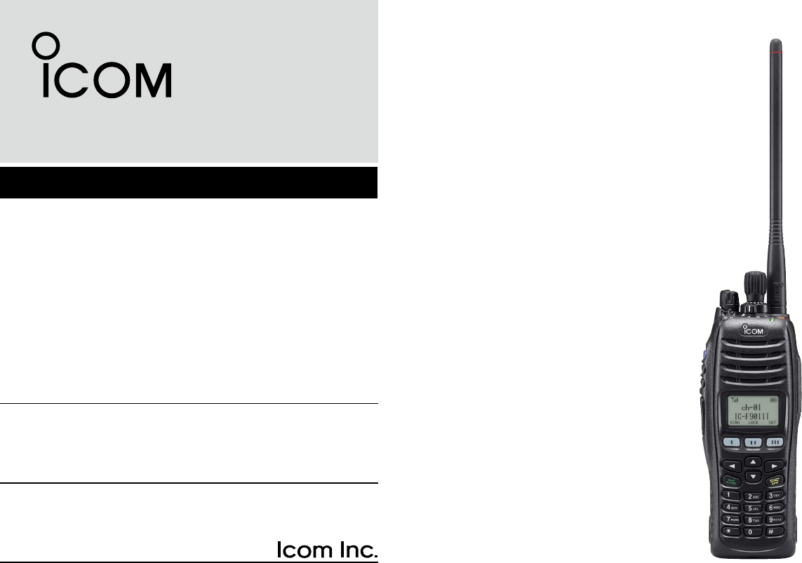
INSTRUCTION MANUAL
UHF P25 TRUNKING
HANDHELD TRANSCEIVERS
iF9011B/S/T
The photo shows the 10-key
type VHF transceiver.
iF9023B/S/T
iF9021B/S/T
VHF P25 TRUNKING
HANDHELD TRANSCEIVERS
i
IMPORTANT
READ ALL INSTRUCTIONS carefully and com-
pletely before using the transceiver.
SAVE THIS INSTRUCTION MANUAL — This
instruction manual contains important operating instructions
for the IC-F9011B/S/T VHF P25 TRUNKING HANDHELD
TRANSCEIVERS and the IC-F9021B/S/T, IC-F9023B/S/T
UHF P25 TRUNKING HANDHELD TRANSCEIVERS.
✔ When the optional UT-125 aes/des encryption
unit is installed:
When you attempt to re-export this product and/or AES en-
cryption of this product is activated, you must comply with the
export regulations of your country, which can be highly restric-
tive. YOUR FAILURE TO COMPLY WITH EXPORT REGULA-
TIONS MAY SUBJECT YOU TO FINES OR PENALTIES. AES
encryption products including this software fall under the con-
trol of the Japanese Government as described in Appendix I:
Export Legal Controls and Appendix: Exchange Legal Con-
trols. Please consult with your dealer or sales representative
for details.
EXPLICIT DEFINITIONS
WORD DEFINITION
RDANGER Personal death, serious injury or an
explosion may occur.
RWARNING Personal injury, fire hazard or electric
shock may occur.
CAUTION Equipment damage may occur.
NOTE
If disregarded, inconvenience only. No risk
of personal injury, fire or electric shock.
See the operating guide for details of Analog and P25
Trunking/Conventional system operations. Consult your
Icom dealer or system operator for details concerning
your transceivers programming.
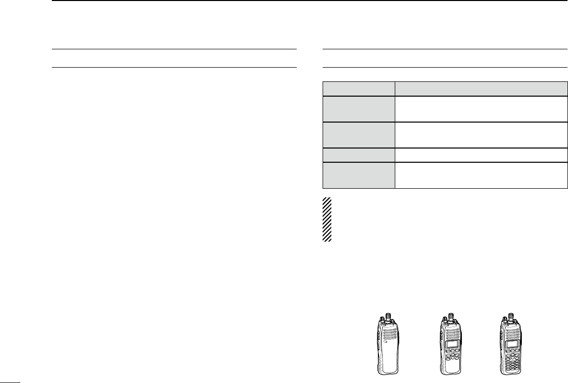
✔ INFORMATION:
In this instruction manual, the following descriptions are used;
IC-F9011B/IC-F9021B/IC-F9023B : “Non display type”
IC-F9011S/IC-F9021S/IC-F9023S : “Simple type”
IC-F9011T/IC-F9021T/IC-F9023T : “10-key type”
10-key typeSimple typeNon display type
Icom, Icom Inc. and the Icom logo are registered trademarks of Icom Incor-
porated (Japan) in the United States, the United Kingdom, Germany, France,
Spain, Russia and/or other countries.
All other products or brands are registered trademarks or trademarks of their
respective holders.

ii
1
2
3
4
5
6
7
8
9
10
11
12
13
14
15
16
FCC INFORMATION
• FOR CLASS B UNINTENTIONAL RADIATORS:
This equipment has been tested and found to comply with
the limits for a Class B digital device, pursuant to part 15 of
the FCC Rules. These limits are designed to provide reason-
able protection against harmful interference in a residential
installation. This equipment generates, uses and can radiate
radio frequency energy and, if not installed and used in ac-
cordance with the instructions, may cause harmful interfer-
ence to radio communications. However, there is no guaran-
tee that interference will not occur in a particular installation.
If this equipment does cause harmful interference to radio or
television reception, which can be determined by turning the
equipment off and on, the user is encouraged to try to cor-
rect the interference by one or more of the following meas-
ures:
• Reorient or relocate the receiving antenna.
• Increase the separation between the equipment and re-
ceiver.
• Connect the equipment into an outlet on a circuit differ-
ent from that to which the receiver is connected.
• Consult the dealer or an experienced radio/TV techni-
cian for help.
ABOUT IPR
This device is made under license under one or more of the
following U.S. Patents: #4,590,473; #4,636,791; #5,148,482;
#5,185,796; #5,271,017; #5,377,229; #4,716,407; #4,972,460;
#5,502,767; #5,146,497; #5,164,986; #5,185,795; #5,164,986,
#5,185,795, and #5,146,497.
* IPR means ‘Intellectual Property Rights.’
VOICE CODING TECHNOLOGY
The AMBE+2™ voice coding Technology embodied in this
product is protected by intellectual property rights including
patent rights, copyrights and trade secrets of Digital Voice
Systems, Inc. This voice coding Technology is licensed sole-
ly for use within this Communications Equipment. The user
of this Technology is explicitly prohibited from attempting to
extract, remove, decompile, reverse engineer, or disassem-
ble the Object Code, or in any other way convert the Object
Code into a human-readable form. U.S. Patent Nos.
#5,870,405, #5,826,222, #5,754,974, #5,701,390,
#5,715,365, #5,649,050, #5,630,011, #5,581,656,
#5,517,511, #5,491,772, #5,247,579, #5,226,084 and
#5,195,166.

iii
R CAUTION! NEVER hold the transceiver so that
the antenna is very close to, or touching exposed parts of
the body, especially the face or eyes, while transmitting. The
transceiver will perform best if the microphone is 5 to 10 cm
(2 to 4 in.) away from the lips and the transceiver is vertical.
R CAUTION! NEVER operate the transceiver with a
headset or other audio accessories at high volume levels.
R CAUTION! NEVER short the terminals of the bat-
tery pack.
R CAUTION! NEVER use non-Icom battery packs/
chargers to prevent the loss of the transceiver’s good per-
formance and warranty.
DO NOT push [PTT] when not actually desiring to transmit.
DO NOT use or place the transceiver in direct sunlight or
in areas with temperatures below –30°C (+22°F) or above
+60°C (+140°F).
The basic operations, transmission and reception of the
transceiver are guaranteed within the specified operating
temperature range. However, the LCD display may not oper-
ate correctly, or show an indication in the case of long hours
of operation, or after being placed in extremely cold areas.
DO NOT modify the transceiver. The transceiver warranty
does not cover any problems caused by unauthorized modi-
fication.
BE CAREFUL! The transceiver meets IP57 require-
ments for dust-protection and waterproof protection. How-
ever, once the transceiver has been dropped, dust-protection
and waterproof protection cannot be guaranteed due to the
fact that the transceiver may be cracked, or the waterproof
seal damaged, etc.
For U.S.A. only
CAUTION! Changes or modifications to this transceiver, not
expressly approved by Icom Inc., could void your authority to
operate this transceiver under FCC regulations.
PRECAUTIONS

1
2
3
4
5
6
7
8
9
10
11
12
13
14
15
16
iv
TABLE OF CONTENTS
IMPORTANT .......................................................................... i
EXPLICIT DEFINITIONS ....................................................... i
FCC INFORMATION ............................................................ ii
ABOUT IPR .......................................................................... ii
VOICE CODING TECHNOLOGY ......................................... ii
PRECAUTIONS ................................................................... iii
TABLE OF CONTENTS ....................................................... iv
1 ACCESSORIES ...........................................................1−2
■ Supplied accessories ...................................................1
■ Accessory attachments ................................................1
2 PANEL DESCRIPTION ..............................................3−11
■ Front panel ...................................................................3
■ Function display (Simple/10-key types only) ................5
■ Programmable function keys ........................................6
3 BASIC OPERATION ................................................12−16
■ Turning power ON ......................................................12
■ Channel selection .......................................................12
■ Receiving and transmitting .........................................13
■ User set mode ............................................................14
■ Clock function .............................................................15
■ LED indicator (Non display type only) ........................16
4 BATTERY CHARGING ............................................17−20
■ Caution .......................................................................17
■ Optional battery chargers ...........................................19
5 BATTERY CASE ............................................................21
■ Optional battery case (BP-237) ..................................21
6 SPEAKER MICROPHONE ............................................22
■ Optional HM-184 description ......................................22
■ To attach .....................................................................22
7 OPTIONS .................................................................23−24
8 SAFETY TRAINING INFORMATION .......................25−26
1
1ACCESSORIES
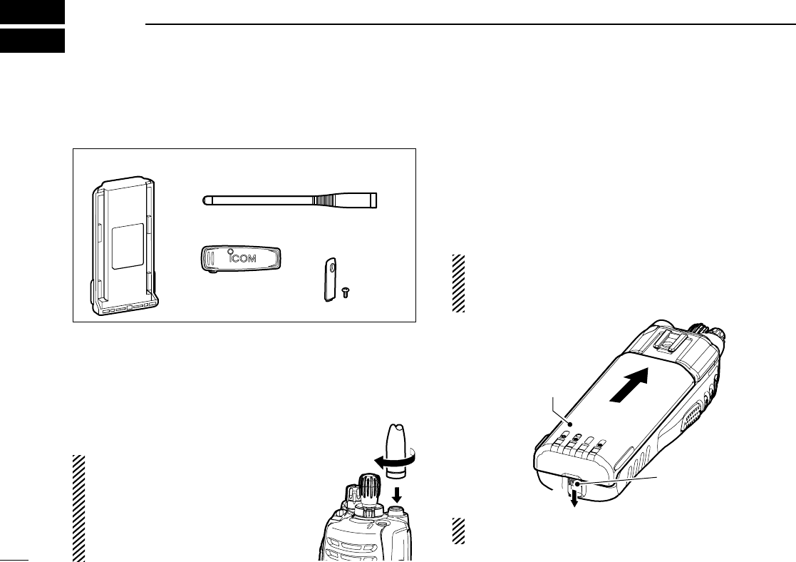
■ Supplied accessories
The following accessories are supplied.
Flexible
antenna
Battery pack
Belt clip Connector cover
(with screw)
■ Accessory attachments
D Flexible antenna
Connect the supplied flexible antenna to the antenna con-
nector.
CAUTION:
• NEVER carry the transceiver by
holding the antenna.
•
DO NOT connect the antenna other
than listed on p. 23.
• Transmitting without an antenna may
damage the transceiver.
D Battery pack
To attach the battery pack:
Slide the battery pack on the back of the transceiver in the direc-
tion of the arrow (q), then lock it with the battery release button.
• Slide the battery pack until the battery release button makes a ‘click’
sound.
To release the battery pack:
Slide the battery release button in the direction of the arrow
(w) as shown below. The battery pack is then released.
NEVER release or attach the battery pack when the trans-
ceiver is wet or soiled. This may result water or dust get-
ting into the transceiver/battery pack and may result in the
transceiver being damaged.
q
Battery release
button
Battery pack
w
NOTE: Keep the battery pack terminals clean. It’s a good
idea to clean the battery pack terminals once a week.
2
1
ACCESSORIES
1
2
3
4
5
6
7
8
9
10
11
12
13
14
15
16
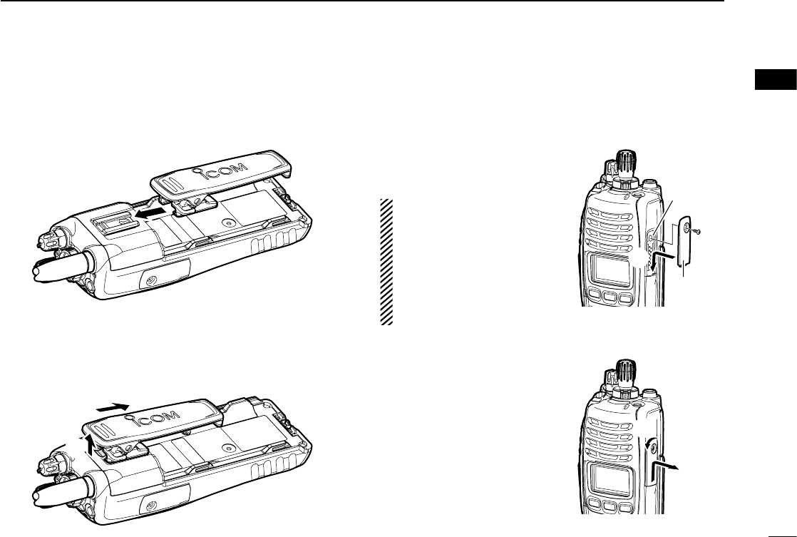
D Belt clip
To attach the belt clip:
q Release the battery pack if it is attached.
w Slide the belt clip in the direction of the arrow until the belt
clip is locked and makes a ‘click’ sound.
To detach the belt clip:
q Release the battery pack if it is attached.
w Pinch the clip (q), and slide the belt clip in the direction of
the arrow (w).
q
w
D Connector cover
Attach the connector cover when the optional equipment is
not used.
To attach the connector cover:
q Insert the connector cover
into the multi-connector.
w Tighten the screw.
CAUTION:
Attach the connector cover
when the optional equipment
is not used. Otherwise the
terminals of the multi-con-
nector may be shorted by
metal object, etc., and this
could damage the transceiver.
To detach the connector cover:
q Unscrew the screw using a
phillips screwdriver.
w Detach the connector cover
for the optional equipment
connector.
Multi-
connector
Connector
cover
q
w
q
w
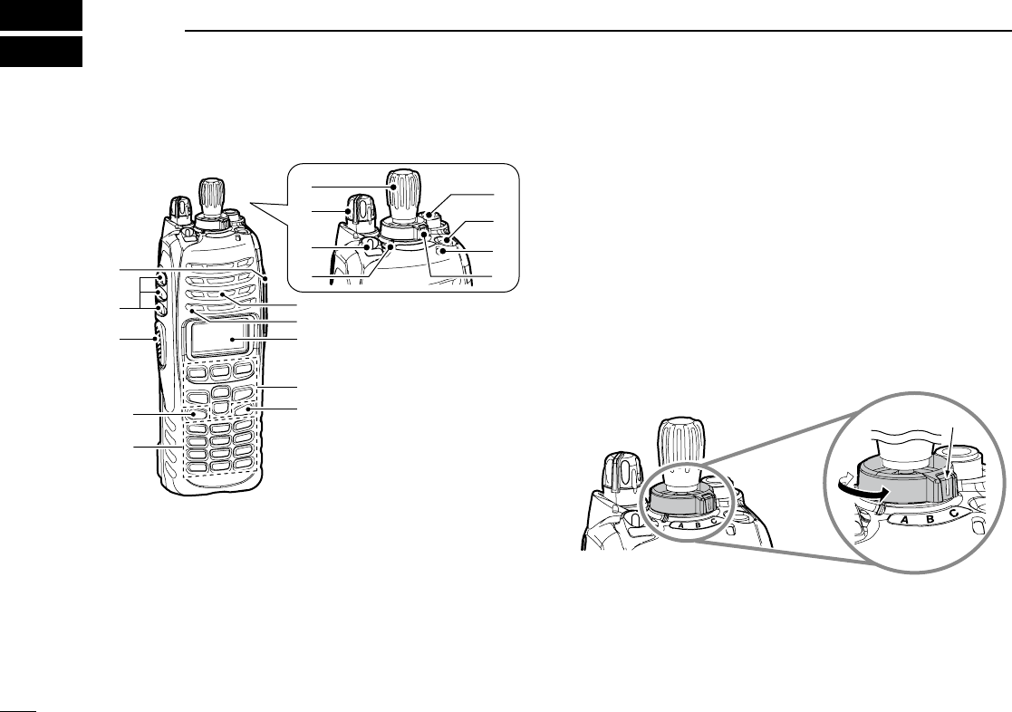
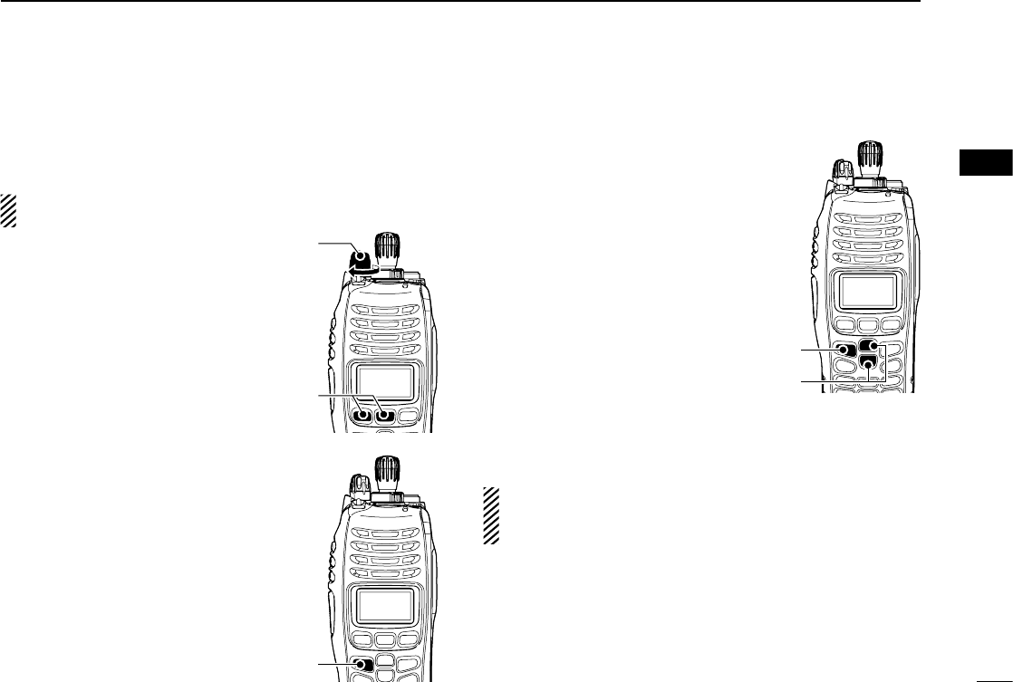
■ Front panel
*1 Simple/10-key types only
*2 10-key type only
Speaker
Microphone
Function display*1
(p. 5)
!0*1
!5
o*1
!1*2
!2*1
!4
!3
e
t
y
u
i
r
w
q
q ANTENNA CONNECTOR
Connects the supplied antenna. (p. 1)
w DEALER-PROGRAMMABLE KEY [EMR]
Desired function can be programmed by your dealer. (p. 6)
• [Emergency] is pre-programmed as default. (See the operating
guide for details.)
e LED INDICATOR
➥
Lights green while receiving a signal, or when the
squelch is open.
➥ Lights red while transmitting.
➥
The LED indicator indicates some information. (Non dis-
play type only) (p. 16)
r DEALER-PROGRAMMABLE ABC SWITCH
Desired function can be programmed to each position
(A, B or C) independently by your dealer. (p. 11)
To activate the pre-programmed function, set the white line
of the ABC switch to the position A, B or C.
When the white line of the ABC switch is
set to the position C, the pre-programmed
function at position C will be activated.
White line
3
2PANEL DESCRIPTION
4
2
PANEL DESCRIPTION
1
2
3
4
5
6
7
8
9
10
11
12
13
14
15
16
t CHANNEL INDICATOR
➥
Lights white according to the “Backlight” setting of the
user set mode.
➥ When you rotate [Rotary selector] to select the channel
or zone, set the desired channel/zone number to this
point.
y DEALER-PROGRAMMABLE TOGGLE SWITCH
Desired function can be programmed by your dealer.
(p. 11)
When the toggle switch is set to the left side (‘ ’), the pre-
programmed function will be activated.
u VOLUME CONTROL [VOL]
Rotate to turn the power ON/OFF and adjusts the audio
level.
i ROTARY SELECTOR
Rotate to select the pre-programmed memory channels or
the operating zone. (Depending on the pre-setting)
• The channel/zone that is positioned to the channel indicator (t)
is selected as the operating channel/zone.
o DEALER-PROGRAMMABLE KEYS
[I]/[II]/[III]/[Ω]/[≈]/[∫]/[√] (Simple/10-key types only)
Desired function can be programmed independently by
your dealer. (p. 6)
!0 APP KEY [APP] (Simple/10-key types only)
Desired function can be programmed by your dealer.
(p. 6)
!1 10-KEYPAD (10-key type only)
The keypad allows you to enter digits to:
• Select memory channels, tone channels and DTMF codes (while
in the DTMF code channel selection mode.)
• Start up with the password
• Input the Individual ID code for digital operation. (Depending on
the pre-setting)
!2 HOME KEY [HOME] (Simple/10-key types only)
Desired function can be programmed by your dealer.
(p. 6)
• [Home] is pre-programmed as default. (See p. 7 for details.)
!3 PTT SWITCH [PTT]
Push and hold to transmit; release to receive.
!4 DEALER-PROGRAMMABLE KEYS
[Side1]/[Side2]/[Side3]
Desired function can be programmed independently by
your dealer. (p. 6)
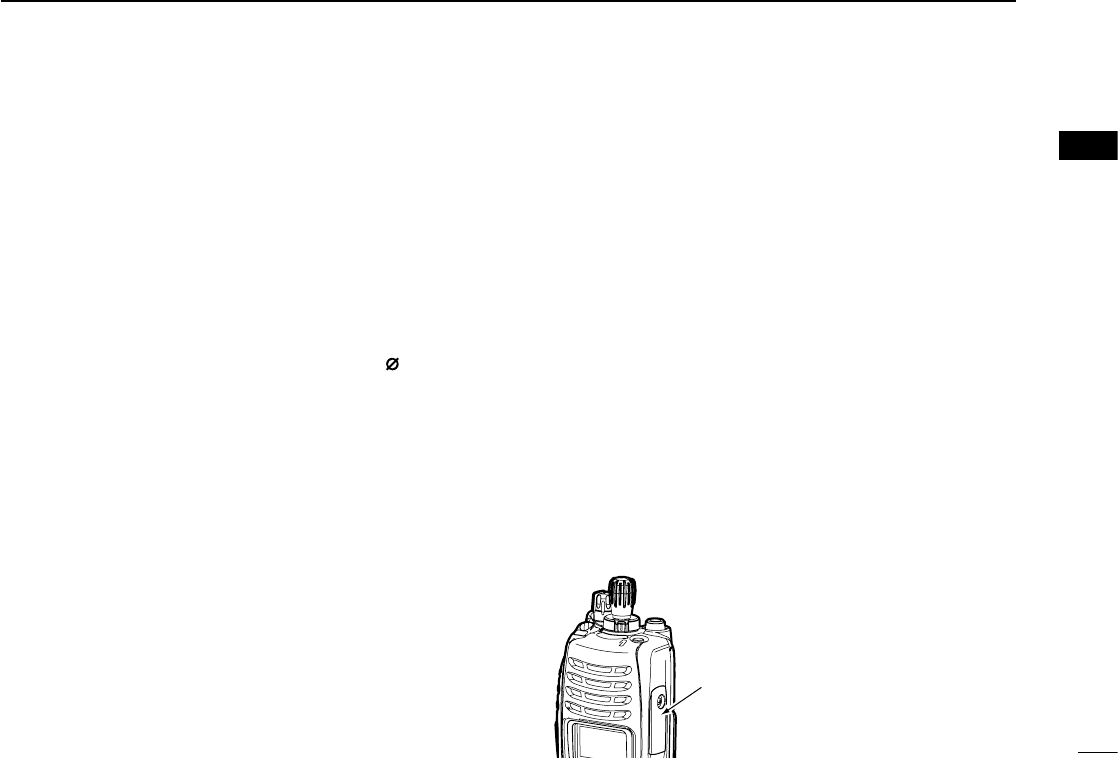
!5 MULTI-CONNECTOR
Connect an optional equipment.
Connector cover
NOTE: Attach the connector cover when
the optional equipment is not used.
See p. 2 for details.
5
2PANEL DESCRIPTION
001
ch
-01
IC
-
F
9011
MON CLCK ZONE !1
q e y ou itrw
!0
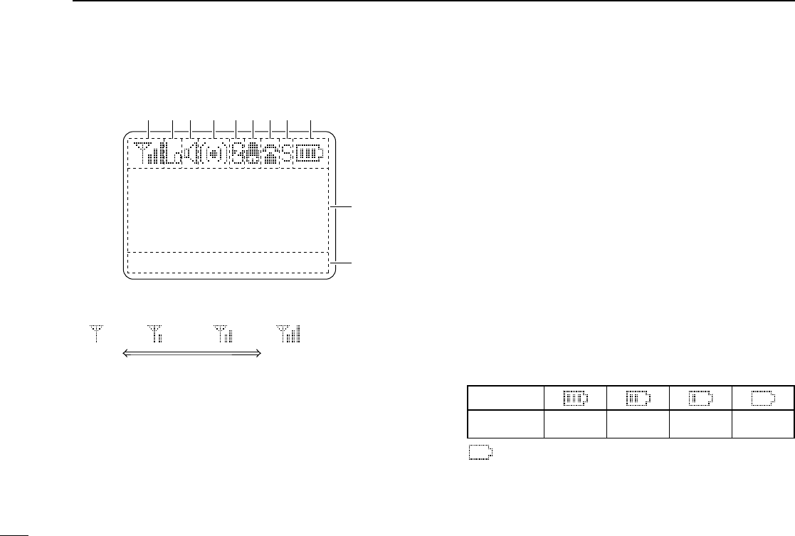
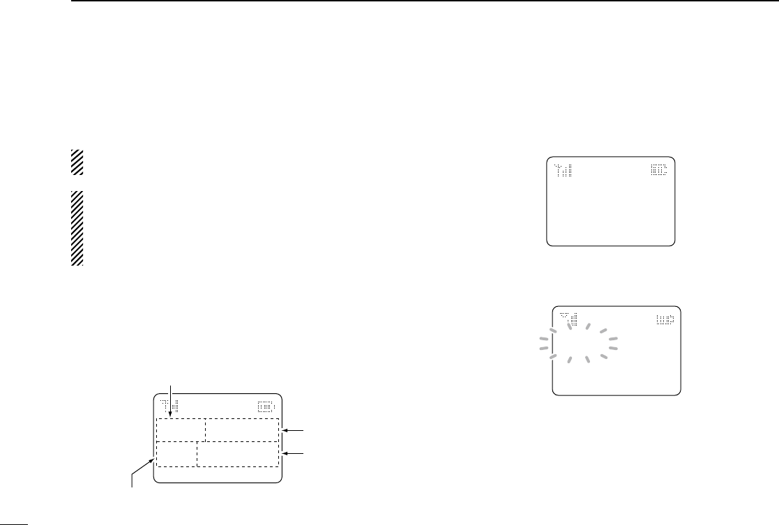
q SIGNAL STRENGTH INDICATOR
Indicates relative signal strength level.
StrongWeak
w LOW POWER INDICATOR
Appears when low output power is selected.
• When high output power is selected, no indicator appears.
e AUDIBLE INDICATOR
Appears when the channel is in the ‘audible’ (unmute) con-
dition.
r COMPANDER INDICATOR
Appears when the compander function* is activated.
* Analog mode operation only.
t SCRAMBLER INDICATOR
Appears when the voice scrambler or encryption function
is activated.
y BELL INDICATOR
Appears/blinks when the specific page call* is received,
according to the pre-programming.
* P25 operation only.
u TELEPHONE INDICATOR
Appears when a phone call* is received.
* P25 operation only.
i SHORT MESSAGE INDICATOR
Appears when an Status message or Short message is
received.
o BATTERY INDICATOR
Appears or blinks when the battery power decreases to a
specified level.
Indication
Battery level Full Middle Charging
required No battery
blinks when the battery is exhausted.
■
Function display (Simple/10-key types only)

6
2
PANEL DESCRIPTION
1
2
3
4
5
6
7
8
9
10
11
12
13
14
15
16
!0 ALPHANUMERIC DISPLAY
Displays an operating channel number, channel name, Set
mode contents, DTMF code, etc.
!1 KEY INDICATOR
Indicate the programmed function of the front panel keys
([I], [II] and [III]).
See the operating guide for details of Analog and P25
Trunking/Conventional system operations. Consult your
Icom dealer or system operator for details concerning your
transceiver’s programming.
■ Programmable function keys
The following functions can be assigned to the following pro-
grammable function keys and switches;
[EMR], [Side1], [Side2], [Side3], [I]*, [II]*, [III]*, [Ω]*, [≈]*, [∫]*,
[√]*, [APP]*, [HOME]*, ABC switch and Toggle switch.
*Simple/10-key types only
Consult your Icom dealer or system operator for details con-
cerning your transceiver’s programming.
If the key indicator shows the programmed function key
name, push the front panel key ([I], [II] or [III]) under the key
indicator to activate the programmed function.
( The function key name in parentheses in the following expla-
nation is displayed for that key indicator; e.g. “UP”)
For Non display type:
The programmable key functions are limited and some key
functions should be operated differently from Simple and
10-key types. (See p. 8 for details.)
For ABC and Toggle switches:
The programmable key functions to ABC and Toggle switches
are limited. (See p. 11 for details.)

7
2PANEL DESCRIPTION
D For All types (Common operation)
PRIO A AND PRIO B KEYS “PRA” “PRB”
Push to select Priority A or Priority B channel.
MR-CH 1, MR-CH 2, MR-CH 3 AND MR-CH 4 KEYS
“CH1” “CH2” “CH3” “CH4”
Push to select the memory channels 1, 2, 3 and 4 directly.
MONI KEY “MON”
Push to mute and release the CTCSS (DTCS), NAC or Talk-
group ID squelch mute. Open any squelch/deactivate any
mute while pushing and holding this key.
LOCK KEY “LOCK”
➥ Push and hold for 1 sec. to electronically lock all program-
mable keys except the following:
[PTT], [Moni], [Light], [Lock], [Emergency Single], [Emergency
Repeat], [Surveillance] and [OPT 1/2/3].
➥ Push and hold for 1 sec. again to turn the lock function
OFF.
LIGHT KEY “LIGT”
Push to turn the transceiver’s backlight ON for about 5 sec.
when the backlight function is turned OFF in user set mode.
(p. 14)
SURVEILLANCE KEY “SURV”
Push to turn the surveillance function ON and OFF.
When this function is turned ON, the beep is not emitted and
the LCD backlight does not light when a signal is received or
a key is pushed, etc.
HOME KEY “HOME”
Push to return to the stand-by mode.
• After editing some information that requires to be memorized, push
this key to save the editing contents in the memory before returning
to the stand-by mode.
OPT MOMENTARY KEYS “O1M” “O2M” “O3M”
Push to control the output signal level from the optional unit
connector.

8
2
PANEL DESCRIPTION
1
2
3
4
5
6
7
8
9
10
11
12
13
14
15
16
D For All types (Different operation with Non display type)
When the following key functions are programmed to Non
display type, the key functions may be limited and some key
functions should be operated differently from Simple and
10-key types.
HIGH/LOW KEY “H/L”
Push to select the transmit output power temporarily or per-
manently, depending on the pre-setting.
• Ask your dealer for the output power level for each selection.
• Emits one beep when Low 1 is selected, two beeps when Low 2 is
selected and three beeps when High is selected. (Non display type
only)
SCAN A KEY “SCNA”
❍ For Simple/10-key types
➥ Push to start and cancel scanning operation.
• When Power ON Scan function is activated, push to pause the
scanning operation. And the paused scan resumes after the
specified time period has passed.
➥
Push and hold this key for 1 sec. to indicate the scan list,
then push [CH Up] or [CH Down] to select the desired list.
(Available depending on the presetting.)
❍ For Non display type
Push to start and cancel scanning operation.
• When Power ON Scan function is activated, push to pause the
scanning operation. And the paused scan resumes after the speci-
fied time period has passed.
• LED indicator blinks green slowly while scanning.
SCAN B KEY “SCNB”
❍ For Simple/10-key types
➥ Push to start and cancel scanning operation.
The scan restarts after the specified time period has
passed when the scan (started with this key) is cancelled
by except for this key operation.
➥
Push and hold this key for 1 sec. to indicate the scan list,
then push [CH Up] or [CH Down] to select the desired list.
❍ For Non display type
Push to start and cancel scanning operation.
• The scan restarts after the specified time period has passed when
the scan (started with this key) is cancelled by except for this key
operation.
• LED indicator blinks green slowly while scanning.
TALK AROUND KEY “TA” (Conventional operation only)
The talk around function equalizes the transmit frequency to
the receive frequency for transceiver-to-transceiver commu-
nication.
❍ For Simple/10-key types
Push to turn the talk around function ON and OFF.
❍ For Non display type
➥ Push and hold for 1 sec. to turn the talk around function
ON.
➥ When the talk around function is ON, push to turn the
function OFF.

2PANEL DESCRIPTION
9
PRIO A REWRITE AND PRIO B REWRITE KEYS
“PRAR” “PRBR”
❍ For Simple/10-key types
➥ Push to select Priority A or Priority B channel.
➥ Push and hold [Prio A (Rewrite)] or [Prio B (Rewrite)] for
1 sec. to rewrite the operating channel as the Priority A or
Priority B channel.
❍ For Non display type
Push to select Priority A or Priority B channel.
COMPANDER KEY “COMP”
The compander function reduces noise components from
the transmitted audio to provide clear communication.
❍ For Simple/10-key types
Push to toggle the compander function ON and OFF.
❍ For Non display type
➥
Push and hold for 1 sec. to turn the compander function ON.
➥ When the compander function is ON, push to turn the
function OFF.
OPT OUT KEYS “OP1” “OP2” “OP3”
❍ For Simple/10-key types
Push to control the output signal level from the optional unit
connector.
❍ For Non display type
➥ Push and hold for 1 sec. to control the output signal level
from the optional unit connector.
➥ When this key function is activated, push to deactivate
the function.
D For Simple/10-key types only
Following key functions cannot be programmed to Non dis-
play type.
CH UP AND DOWN KEYS “UP” “DOWN”
➥ Push to select an operating channel. When [Rotary selec-
tor] selection mode is “operating channel,” this function is
not available.
➥ Push to select a scan group after pushing and holding
[Scan A Start/Stop]/[Scan B Start/Stop].
ZONE KEY “ZONE”
Push this key, then push [CH Up] or [CH Down] to select the
desired zone.
When [Rotary selector] selects “operating zone,” push this
key to switch the range of selectable zones.
What is “zone”?— Selected channels are assigned to a zone
according to how they are to be used in a group. For example,
‘Staff A’ and ‘Staff B’ are assigned into a “Business” zone, and
‘John’ and ‘Cindy’ are assigned into a “Private” zone.
USER SET MODE KEY “SET”
➥ Push and hold for 1 sec. to enter user set mode.
• During in the user set mode, push this key to select an item that
is enabled by your dealer, and change the value or condition by
pushing [CH Up] or [CH Down].
➥
Push and hold this key for 1 sec. again to exit user set mode.
User set mode is also available via the ‘Power ON func-
tion.’ Refer to p. 14 also.
10
2
PANEL DESCRIPTION
1
2
3
4
5
6
7
8
9
10
11
12
13
14
15
16
CLOCK KEY “CLCK”
Push to indicate the current time on the LCD. (p. 15)
• While the current time is indicated, push and hold this key for
1 sec. to enter the time data edit mode.
SCAN ADD/DEL (TAG) KEY “SCAD”
Push to add or delete the selected channel to/from the scan
list.
1. Push to indicate the scan list, then push [CH Up] or
[CH Down] to select the desired list.
2. Push to add or delete the channel to/from the selected
scan list.
3. Push and hold for 1 sec. to exit the scan list selection
mode.
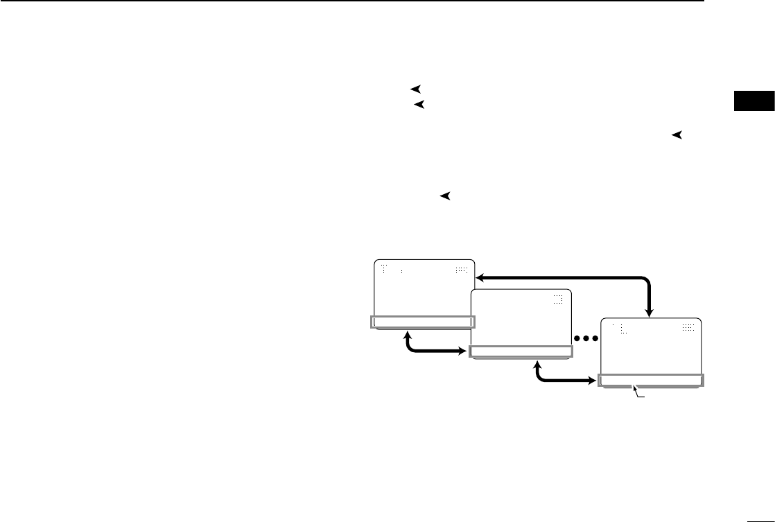
MENU AND MENU ➤ KEYS
( [Menu ] and [Menu ➤] can only be assigned to [Ω] and
[≈], respectively.)
The menu mode is available when either [Menu ] or
[Menu ➤] is assigned to [Ω] or [≈].
During menu mode, the pre-programmed menu items (up to
15) become effective with [I], [II] and [III] keys.
Push [Menu ]/[Menu ➤] to switch the previous/next 3 menu
items, and push [I], [II] or [III] to activate the programmed
function.
During menu mode
Push [Menu
�
]
or [Menu�]
Push [Menu
�
]
or [Menu�]
Push [Menu
�
] or [Menu�]
001
ch
-01
IC
-
F
9011
MON CLCK ZONE
001
ch
-01
IC
-
F
9011
LOCK LIGT SET
001
ch
-01
IC
-
F
9011
SCNA PRA CH1
Menu items

2PANEL DESCRIPTION
11
D For ABC and Toggle switches only
ZONE SWITCH
Selects the pre-programmed zone directly.
PRIO A AND PRIO B SWITCHES
Selects Priority A or Priority B channel.
MR-CH 1, MR-CH 2, MR-CH 3 AND MR-CH 4 SWITCHES
Selects the memory channels 1, 2, 3 and 4, directly.
TALK AROUND SWITCH (Conventional operation only)
Turns the talk around function ON and OFF.
• The talk around function equalizes the transmit frequency to the
receive frequency for transceiver-to-transceiver communication.
LOCK SWITCH
Turns the lock function ON and OFF.
All programmable keys except the following are locked:
[PTT], [Moni], [Light], [Lock], [Emergency Single],
[Emergency Repeat], [Surveillance] and [OPT 1/2/3].
HIGH/LOW SWITCH
Selects the transmit output power temporarily.
• Ask your dealer for the output power level for each selection.
SURVEILLANCE SWITCH
Turns the surveillance function ON or OFF.
When this function is turned ON, the beep is not emitted and
the LCD backlight does not light when a signal is received or
a key is pushed, etc.
COMPANDER SWITCH
Turns the compander function ON and OFF.
The compander function reduces noise components from
the transmitted audio to provide clear communication.
OPT MOMENTARY SWITCHES
Controls the output signal level from the optional unit con-
nector.
12
3
BASIC OPERATION
1
2
3
4
5
6
7
8
9
10
11
12
13
14
15
16
■ Turning power ON
• Prior to using the transceiver for the first time, the battery
pack must be fully charged for optimum life and opera-
tion. (p. 17)
• When you use the transceiver for the first time, or after
the transceiver has sat unused for a long time, make
sure to check the date and time indication after turning
the power ON. If the time and date are not correct, reset
them. (p. 15)
q Rotate [VOL] to turn the power ON.
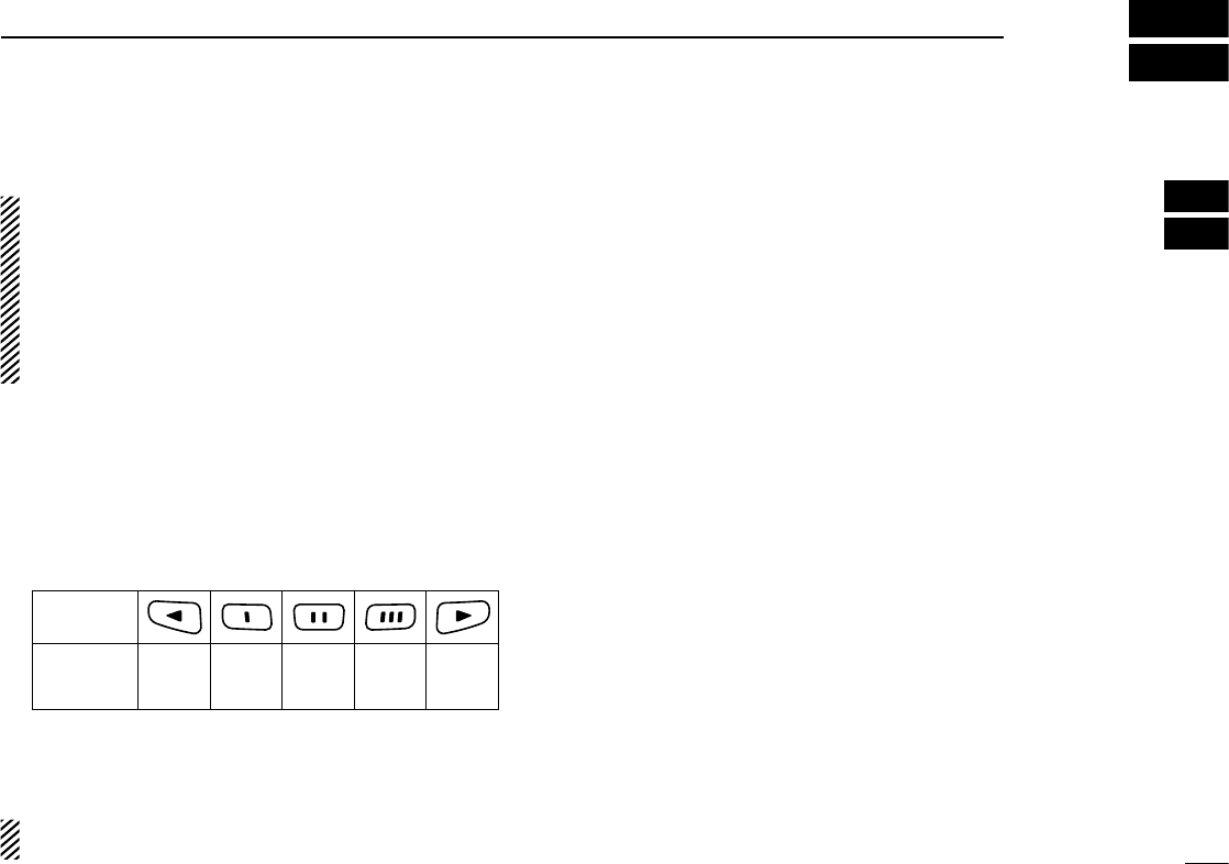
w If the transceiver is programmed for a start up password,
input the digit codes as directed by your dealer.
• 10-keypad can be used for password input depending on ver-
sion.
• The keys in the table below can be used for password input.
• The transceiver detects numbers in the same block as identical.
Therefore “01234” and “56789” are the same.
KEY
NUMBER 0
5
4
9
3
8
2
7
1
6
e When the “PASSWORD” indication does not clear after in-
putting 6 digits, the input code number may be incorrect.
Turn the power off and start over in this case.
When you operate Non display type, the password setting
is not available.
■ Channel selection
Several types of channel selections are available. Methods
may differ according to your system set up.
NON-ZONE TYPE:
To select the desired operating channel:
• Push [CH Up] or [CH Down].
• Rotate [ROTARY SELECTOR]*.
- Up to pre-programmed 16 channels can be selected.
• Push one of [MR-CH 1] to [MR-CH 4].
ZONE TYPE:
To select the desired zone:
• Push [Zone], then push [CH Up] or [CH Down].
• Rotate [ROTARY SELECTOR]*.
- Up to pre-programmed 16 zones can be selected.
AUTOMATIC SCAN TYPE:
Channel setting is not necessary for this type. When turn-
ing power ON, the transceiver automatically starts scanning.
Scanning stops when receiving a call.
* Depending on the pre-setting.
When [Rotary selector] selects “Operating channel,” [CH Up]/[CH
Down] are not available.
When [Rotary selector] selects “Operating zone,” [Zone]/[Zone Up]/
[Zone Down] are not available.

■ Receiving and transmitting
NOTE: Transmitting without an antenna may damage the
transceiver. See p. 1 for accessory attachments.
Receiving:
q Rotate [VOL] to turn the power ON.
w Push [CH Up] or [CH Down], or rotate [ROTARY SELEC-
TOR]* to select a channel, in sequence.
*Depending on the pre-setting.
e When receiving a call, adjust the audio output level to a
comfortable listening level.
Transmitting:
Wait for the channel to become clear to avoid interference.
q While pushing and holding [PTT], speak into the micro-
phone at a normal voice level.
w Release [PTT] to return to receive.
IMPORTANT: To maximize the audio quality of your signal;
1. Pause briefly after pushing [PTT].
2. Hold the microphone 5 to 10 cm (2 to 4 in.) from your
mouth, then speak into the microphone at a normal
voice level.
D Transmitting notes
• Transmit inhibit function
The transceiver has several inhibit functions which restrict
transmission under the following conditions:
- The channel is in mute condition (‘Inaudible’ condition;
“ ” does not appear.)
- The channel is busy.
- Un-matched (or matched) CTCSS is received.
(Depending on the pre-setting.)
- Un-matched (or matched) NAC is received*.
(Depending on the pre-setting.)
*Digital mode operation only.
- The selected channel is a ‘receive only’ channel.
• Time-out timer
After continuous transmission for the pre-programmed time
period, the time-out timer is activated, causing the trans-
ceiver to stop transmitting.
• Penalty timer
Once the time-out timer is activated, transmission is further
inhibited for a period determined by the penalty timer.
13
3BASIC OPERATION
14
3
BASIC OPERATION
1
2
3
4
5
6
7
8
9
10
11
12
13
14
15
16
■ User set mode
The user set mode is accessed at power ON and allows you
to set seldom-changed settings. You can “customize” the trans-
ceiver operation to suit your preferences and operating style.
When you operate Non display type, this function is not
available.
Entering the user set mode:
q While pushing and holding [I] and
[II], rotate [VOL] to turn the power
ON.
• Turn power OFF in advance.
• “SET MODE” appears for 1 sec at
power ON.
w Push and hold [Ω] to enter user
set mode.
e Push [Ω] several times to select
the appropriate item.
Then push [∫] or [√] to set the
desired level/condition.
• Available set mode functions are
Backlight, LCD contrast, Beep,
Beep Level, Ringer Level, SQL
Level, AF Min Level, Mic Gain,
VOX Gain*, VOX Delay*, Horn,
Battery Voltage, Signal Moni and
System info.
* Appears only when the external
VOX unit is connected. The VOX
unit is available in the near future.
r Push and hold [Ω] again to exit
the user set mode.
• Until turning power OFF, [Ω], [∫] and [√] is not activated as the
assigned key function.
NOTE: While in the user set mode, [Ω], [∫] and [√] are
activated as described above regardless of the assigned
key function.
User set mode is also available using a programmable key.
Refer to p. 9 [User Set Mode] section for instructions regard-
ing using the key assigned for user set mode.
[VOL]
[I]/[II]
[Ω]
[Ω]
[∫]/[√]
3BASIC OPERATION
15
■ Clock function
The transceiver indicates the current time and date when
[Clock] is pushed. And you can change the indication format
and time/date settings.
When you operate Non display type, this function is not
available.
When you use the transceiver for the first time, or after the
transceiver has sat unused for a long time, make sure to
check the date and time indication after turning the power
ON. If the time and date are not correct, reset them. (See
‘Time and date settings’ at right.)
D Time and date indication
q
Push [Clock] to indicate the current time and date on the LCD.
• When the indication format is set to 12-hour, “AM” or “PM” is
indicated.
• The LCD indication returns to the stand-by mode after 30 sec.
has passed with no operation.
12
HR
12:00
PM
YMD
08-04-01
MUTE CLOCK ZONE
Date indication format (Y: Year, M: Month, D: Day)
The time indication format (12-hour/24-hour)
Time
Date
w Push [Clock] again to return to the stand-by mode.
D Time and date settings
q Push [Clock] to indicate the current time and date on the
LCD.
12
HR
12:00
PM
YMD
08-04-01
MUTE CLOCK ZONE
w Push and hold [Clock] for 1 sec. to enter the time and date
setting mode.
• The time indication format, “24HR” or “12HR” blinks.
12
HR
12:00
PM
YMD
08-04-01
MUTE CLOCK ZONE
e Push [Clock] to select the desired item to be changed.
16
3
BASIC OPERATION
1
2
3
4
5
6
7
8
9
10
11
12
13
14
15
16
r Push [CH Up] or [CH Down] to set the selected item.
12
HR
03:00
PM
YMD
08-04-01
MUTE CLOCK ZONE
t Push [Clock] to set.
• The next item blinks.
12
HR
03:00
PM
YMD
08-04-01
MUTE CLOCK ZONE
y Repeat steps e to t to set items.
u After setting, push and hold [Clock] for 1 sec. to program.
• Return to the time and date setting mode.
i Push [Clock] to return to the stand-by mode.
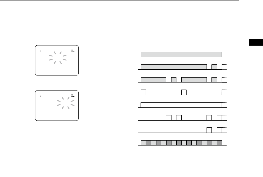
■ LED indicator (Non display type only)
The LED indicator indicates some information as follows;
(Ref.; R=Red, G=Green, O=Orange)
• TX: Lights Red while transmitting a signal.
TX Low BATT1
O O
G G G G
G G
G G G G G G G G
R G R G R G R G R G R G R G R G
R O R O R O R O R O R O R O R O
G
G G
Clone Err
Clone TX/RX
Low BATT2
Low BATT1
Inh & Blank CH
Busy
F/S Scan
Call LED Blink
Call LED ON
TX Low BATT2
TX R*
R* R*
R* R* R*R*
O
*
Lights (or blinks) orange when the optional battery case is at-
tached.
• TX low BATT1: Low BATT1 was detected during TX mode.
• TX low BATT2: Low BATT2 was detected during TX mode.
• Fast/Slow scan: Blinks while Fast/Slow scan is activated.
• RX: Turns Green while receiving a signal.
• Low BATT1: You should charge the battery. (blinks slowly)
• Low BATT2: You must charge the battery. (blinks fast)
• CH err: Non-programmed channel is selected.

■ Caution
• R DANGER! Use and charge only specified Icom battery
packs with Icom radios or Icom chargers. Only Icom bat-
tery packs are tested and approved for use and charge with
Icom radios or Icom chargers. Using third-party or coun-
terfeit battery packs or chargers may cause smoke, fire, or
cause the battery to burst.
D Battery caution
• R DANGER! DO NOT hammer or otherwise impact the bat-
tery. Do not use the battery if it has been severely impacted
or dropped, or if the battery has been subjected to heavy
pressure. Battery damage may not be visible on the outside
of the case. Even if the surface of the battery does not show
cracks or any other damage, the cells inside the battery may
rupture or catch fire.
•
R DANGER! NEVER use or leave battery packs in areas
with temperatures above +60˚C (+140˚F). High tempera-
ture buildup in the battery, such as could occur near fires
or stoves, inside a sun heated car, or in direct sunlight may
cause the battery to rupture or catch fire. Excessive tem-
peratures may also degrade battery performance or shorten
battery life.
•
R DANGER! DO NOT expose the battery to rain, snow,
seawater, or any other liquids. Never charge or use a wet
battery. If the battery gets wet, be sure to wipe it dry before
using.
•
R DANGER! NEVER incinerate used battery packs since
internal battery gas may cause them to rupture, or may
cause an explosion.
•
R DANGER! NEVER solder the battery terminals or
NEVER modify the battery pack. This may cause heat gen-
eration, and the battery may rupture, emit smoke or catch
fire.
•
R DANGER! Use the battery only with the transceiver for
which it is specified. Never use a battery with any other
equipment, or for any purpose that is not specified in this
instruction manual.
•
R DANGER! If fluid from inside the battery gets in your
eyes, blindness can result. Rinse your eyes with clean water,
without rubbing them, and see a doctor immediately.
17
4BATTERY CHARGING
Misuse of Lithium-Ion batteries may result in the fol-
lowing hazards: smoke, fire, or the battery may rupture.
Misuse can also cause damage to the battery or degra-
dation of battery performance.

18
4
BATTERY CHARGING
1
2
3
4
5
6
7
8
9
10
11
12
13
14
15
16
• WARNING! Immediately stop using the battery if it emits
an abnormal odor, heats up, or is discolored or deformed. If
any of these conditions occur, contact your Icom dealer or
distributor.
•
WARNING! Immediately wash, using clean water, any part
of the body that comes into contact with fluid from inside
the battery.
•
WARNING! NEVER put the battery in a microwave oven,
high-pressure container, or in an induction heating cooker.
This could cause a fire, overheating, or cause the battery
to rupture.
•
CAUTION! Always use the battery within the specified tem-
perature range for the transceiver (–30˚C to +60˚C; –22˚F
to +140˚F) and the battery itself (–20˚C to +60˚C; –4˚F to
+140˚F). Using the battery out of its specified temperature
range will reduce the battery’s performance and battery life.
•
CAUTION! Shorter battery life could occur if the battery is
left fully charged, completely discharged, or in an exces-
sive temperature environment (above +45˚C; +113˚F) for an
extended period of time. If the battery must be left unused
for a long time, it must be detached from the radio after dis-
charging. You may use the battery until the remaining ca-
pacity is about half, then keep it safely in a cool dry place
with the temperature range as below;
–20˚C to +45˚C (–4˚F to +113˚F) (within a month)
–20˚C to +35˚C (–4˚F to +95˚F) (within three months)
–20˚C to +25˚C (–4˚F to +77˚F) (within a year)
D Charging caution
• R DANGER! NEVER charge the battery pack in areas with
extremely high temperatures, such as near fires or stoves,
inside a sun heated car, or in direct sunlight. In such en-
vironments, the safety/protection circuit in the battery will
activate, causing the battery to stop charging.
•
WARNING! NEVER charge or leave the battery in the bat-
tery charger beyond the specified time for charging. If the
battery is not completely charged by the specified time, stop
charging and remove the battery from the battery charger.
Continuing to charge the battery beyond the specified time
limit may cause a fire, overheating, or the battery may rup-
ture.
•
WARNING! NEVER insert the transceiver (battery attached
to the transceiver) into the chargers if it is wet or soiled. This
could corrode the battery charger terminals or damage the
chargers. The chargers are not waterproof.
•
CAUTION! NEVER charge the battery outside of the speci-
fied temperature range: 0˚C to +40˚C (+32˚F to +104˚F).
Icom recommends charging the battery at +20˚C (+68˚F).
The battery may heat up or rupture if charged out of the
specified temperature range. Additionally, battery perform-
ance or battery life may be reduced.
4BATTERY CHARGING
19
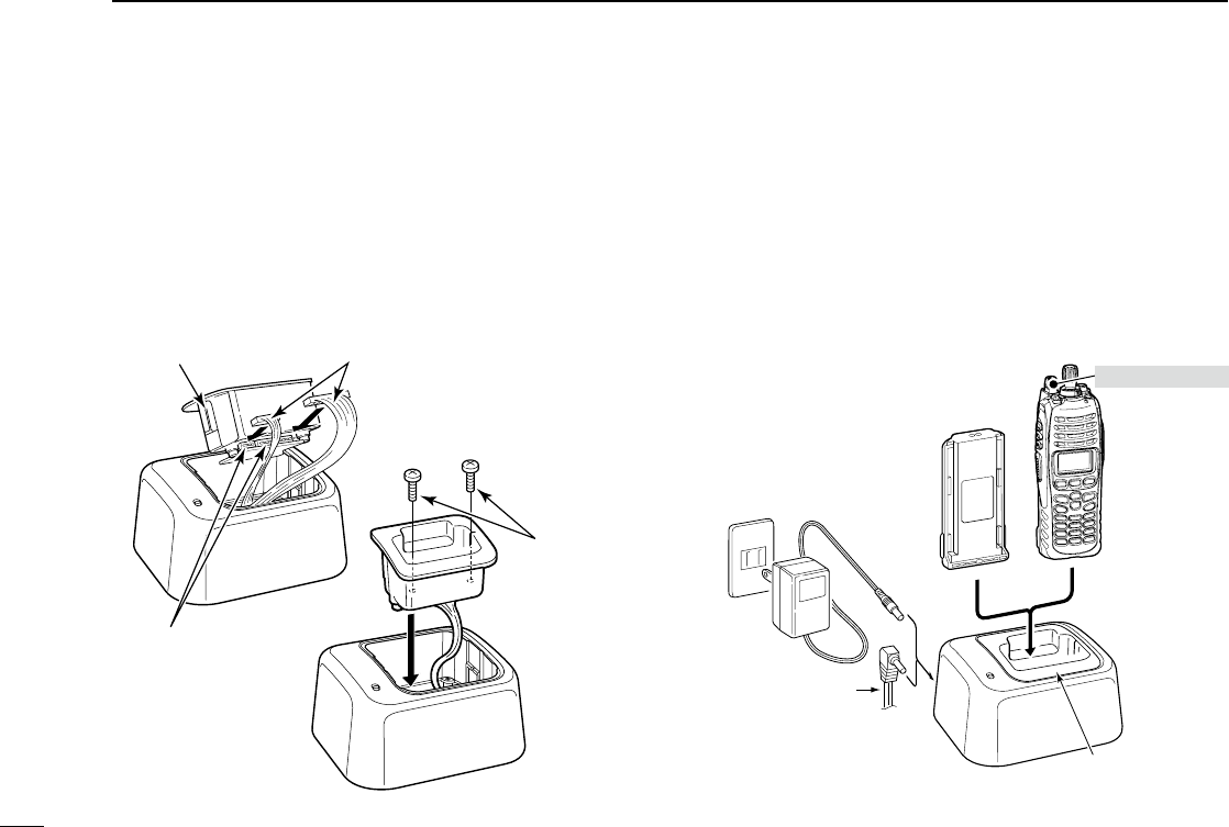
■ Optional battery chargers
D AD-110 installation
The AD-110 charger adapter must be installed into the BC-
119N or BC-121N before battery charging.
➥ Connect the AD-110 charger adapter and the BC-119N/
BC-121N as below, then install the AD-110 into the holder
space of the BC-119N or BC-121N with the supplied
screws.
D Rapid charging with the BC-119N+AD-110
The optional BC-119N provides rapid charging of the Li-Ion
battery pack. Charging period: Approx. 4 hours (with BP-254)
The following items are additionally required.
• AD-110 charger adapter (purchase separately)
• An AC adapter (may be supplied with BC-119N depending
on version) or the DC power cable (OPC-515L/CP-17L).
AD-110 charger
adapter is installed
in BC-119N.
BATTERY
PACK TRANSCEIVER
AC adapter
(Not supplied
with some
versions.)
Optional OPC-515L
(for 13.8 V power
source) or CP-17L
(for 12 V cigarette
lighter socket) can
be used instead of
the AC adapter.
Turn power OFF
This illustration shows the BC-119N.
AD-110
Screws supplied
with the charger
adapter
Plugs
Connectors
20
4
BATTERY CHARGING
1
2
3
4
5
6
7
8
9
10
11
12
13
14
15
16
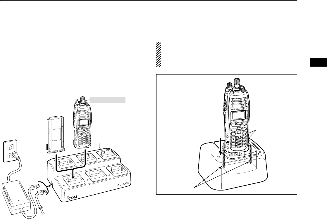
D Rapid charging with the BC-121N+AD-110
The optional BC-121N allows up to 6 battery packs to be
charged simultaneously. Charging period: Approx. 4 hours
(with BP-254)
The following items are additionally required.
• Six AD-110 charger adapters (purchase separately)
• An AC adapter (BC-157) or the DC power cable (OPC-656)
MULTI-CHARGER
AC adapter
(Purchased
separately)
AD-110 charger
adapters are installed
in each slot.
BATTERY
PACK
DC power cable (OPC-656)
(Connect with the DC power supply;
13.8 V/at least 7 A)
TRANSCEIVER
Turn power OFF
IMPORTANT: Battery charging caution
Ensure the guide lobes on the battery pack are correctly
aligned with the guide rails inside the charger adapter.
(This illustration shows the BC-119N.)
Guide rails
Lobs
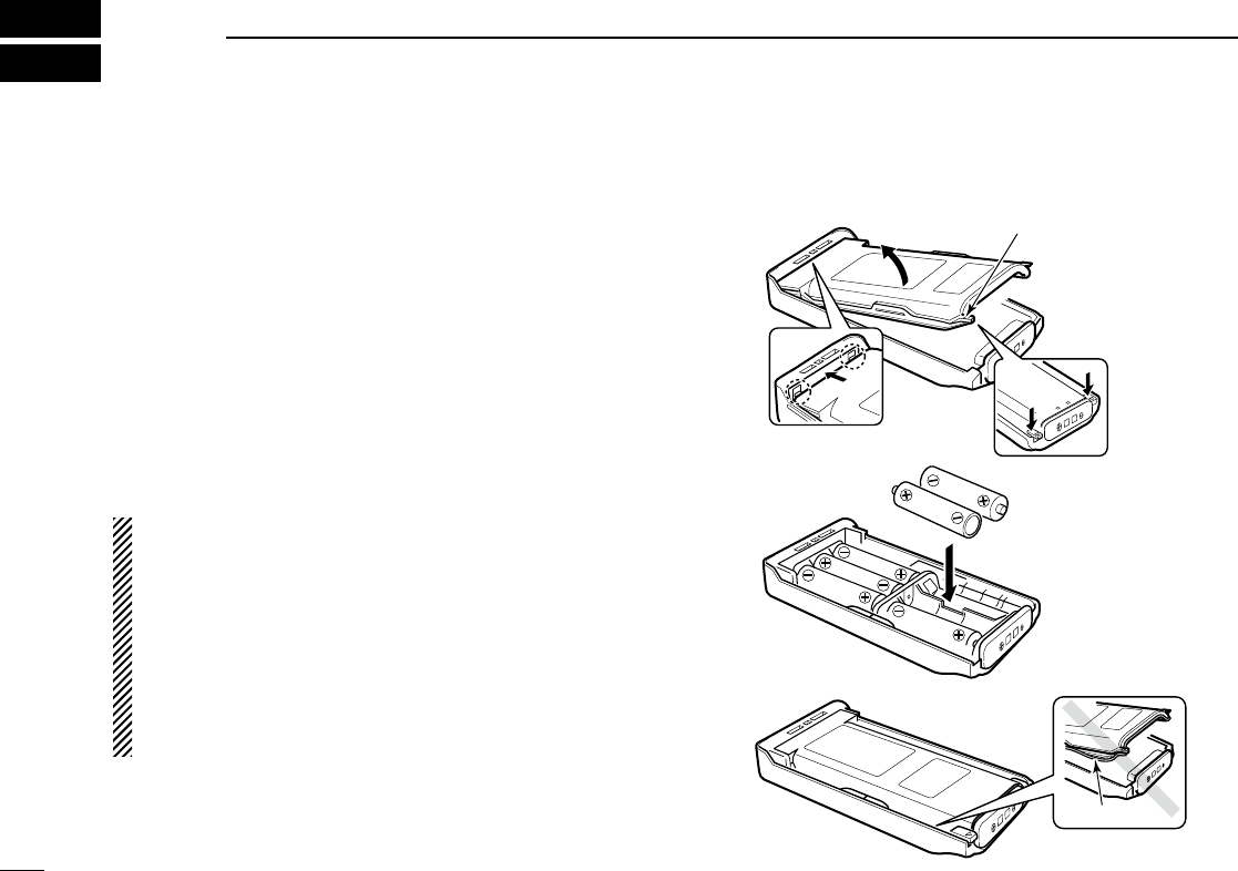
■ Optional battery case (BP-237)
The optional battery case uses 6 × AA (LR6) size alkaline
batteries. The battery case offers low output power.
q Hook your finger under the latch, and open the cover in
the direction of the arrow (q). (Fig.1)
w Then, install 6 × AA (LR6) size alkaline batteries. (Fig.2)
• Install the alkaline batteries only.
• Be sure to observe the correct polarity.
• Do not pin the ribbon under the batteries.
e Close the cover by fitting in the direction of the arrow (w)
first, then check the latch is in place (e). (Fig.1)
• Be sure the gasket is set correctly, and do not protrude from the
battery case. (Fig.3)
CAUTION:
• When installing batteries, make sure they are all the same
brand, type and capacity. Also, do not mix new and old
batteries together.
• Keep battery contacts clean. It’s a good idea to clean bat-
tery terminals once a week.
• Never incinerate used battery cells since internal battery
gas may cause them to rupture.
• Never expose a detached battery case to water. If the bat-
tery case gets wet, be sure to wipe it dry before using it.
q
BP-237
Fig.1
Fig.2
Fig.3
e
Latch
w
Gasket
21
5BATTERY CASE
22
6
SPEAKER MICROPHONE
1
2
3
4
5
6
7
8
9
10
11
12
13
14
15
16
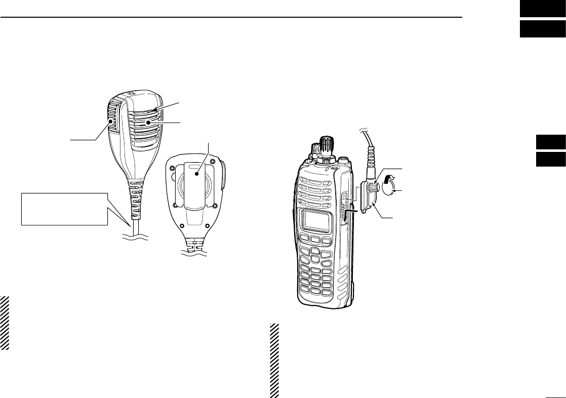
■ Optional HM-184 description
Turn the transceiver
power OFF while con-
necting the HM-184.
Speaker
Belt clip
Microphone
PTT SWITCH
Push and hold to
transmit;
release to receive.
NEVER immerse the connector in water. If the connector gets
wet, be sure to dry it BEFORE attaching it to the transceiver.
NOTE: The microphone is located as shown in the dia-
gram above. To maximize the readability of your transmit-
ted signal (voice), hold the microphone approx. 5 to 10 cm
(2 to 4 in.) from your mouth, and speak in a normal voice
level.
■ To attach
Attach the connector of the speaker-microphone into the
multi connector on the transceiver and tighten the screw with
a coin or flat head screwdriver.
CAUTION: Attach the
multi connector properly,
but do not overtighten.
A loose connection will al-
low water intrusion into the
connector; an overtight-
ened connection will dam-
age the connector pins in
the transceiver.
Coin
Screw
IMPORTANT: KEEP the connector cover attached to the
transceiver when the speaker-microphone is not in use.
(p. 3)
Water will not get into the transceiver even if the cover is
not attached; however, the terminals (pins) will become
rusty, or the transceiver will function abnormally if the con-
nector gets wet.

7OPTIONS
23
D BATTERY PACKS
Battery pack Voltage Capacity Battery life*3
BP-254*17.4 V 2900 mAh (min.)
3040 mAh (typ.) 9.5 hrs.
BP-237*2Battery case for
A6 × AA (LR6) alkaline —*4
*1
The BP-254 meets IPX7* requirements for waterproof protection.
When it is connected, the transceiver corresponds to IPX7.
*2
The BP-237 meets IPX4* requirements for splash resistance.
When it is connected, the transceiver corresponds to IPX4.
*3
When the power save function is turned ON, and the operating
periods are calculated under the following conditions;
TX : RX : standby = 5 : 5 : 90
*4 Operating period depends on the alkaline cells used.
D CHARGERS
• BC-119N desktop charger + AD-110 charger adapter
+ BC-145 ac adapter
For rapid charging of battery pack. An AC adapter is sup-
plied with the charger depending on versions.
Charging time: approx. 4 hours when BP-254 is attached.
• BC-121N multi-charger + AD-110 charger adapter
(6 pcs.) + BC-157 ac adapter
For rapid charging of up to 6 battery packs (six AD-110s
are required) simultaneously. An AC adapter should be pur-
chased separately.
Charging time: approx. 4 hours when BP-254 is attached.
D CABLES
• CP-17L cigarette lighter cable
Allows charging of the battery pack through a 12 V cigarette
lighter socket. (For BC-119N)
• OPC-515L/OPC-656 dc power cables
Allows charging of the battery pack using a 13.8 V power
source instead of the AC adapter.
OPC-515L : For BC-119N
OPC-656 : For BC-121N
• OPC-1870/OPC-1871 zone copy cables
OPC-1870 : Portable to portable zone copy cable.
OPC-1871 : Portable to mobile zone copy cable.
See the operating guide for details.
D OPTIONAL UNITS
• UT-124R man down unit
Provides a measure of safety when working in a hazardous
environment, etc.
• UT-125 aes/des encryption unit
D ANTENNAS
• FA-S25V/S65V/S66V/S30U/S58U/S75U flexible antennas
FA-S25V : 136–148 MHz FA-S30U : 380–430 MHz
FA-S65V : 148–160 MHz FA-S58U : 430–470 MHz
FA-S66V : 160–174 MHz FA-S75U : 470–520 MHz

24
7
OPTIONS
1
2
3
4
5
6
7
8
9
10
11
12
13
14
15
16
D OTHER OPTIONS
• MB-115 belt clip
Exclusive alligator-type belt clip.
• HM-184 speaker-microphone
Rugged type speaker-microphone.
*
The HM-184 meets IP57* requirements for waterproof protection.
When it is connected, the transceiver corresponds to IP57.
* Once these items have been dropped, the IP rating cannot
be guaranteed because of possible damage to these cases
or the waterproof seal.
Icom optional equipment is designed for optimal perform-
ance when used with this transceiver. We are not respon-
sible for the transceiver being damaged or any accident
caused when using non-Icom optional equipment.
Some options may not available in some countries. Please
ask your dealer for details.
W AR N IN G
Your Icom radio generates RF electromagnetic en-
ergy during transmit mode. This radio is designed
for and classified as “Occupational Use Only”,
meaning it must be used only during the course of
employment by individuals aware of the hazards,
and the ways to minimize such hazards. This radio
is NOT intended for use by the “General Population” in an uncon-
trolled environment.
This radio has been tested and complies with the FCC RF ex-
posure limits for “Occupational Use Only”. In addition, your Icom
radio complies with the following Standards and Guidelines with
regard to RF energy and electromagnetic energy levels and eval-
uation of such levels for exposure to humans:
• FCC OET Bulletin 65 Edition 97-01 Supplement C, Evaluat-
ing Compliance with FCC Guidelines for Human Exposure to
Radio Frequency Electromagnetic Fields.
• American National Standards Institute (C95.1-1992), IEEE
Standard for Safety Levels with Respect to Human Exposure
to Radio Frequency Electromagnetic Fields, 3 kHz to 300
GHz.
• American National Standards Institute (C95.3-1992), IEEE
Recommended Practice for the Measurement of Potentially
Hazardous Electromagnetic Fields– RF and Microwave.
• The following accessories are authorized for use with this
product. Use of accessories other than those specified may
result in RF exposure levels exceeding the FCC requirements
for wireless RF exposure.; Belt Clip (MB-115), Rechargeable
Li-Ion Battery Pack (BP-254), Alkaline Battery Case (BP-
237) and Speaker-microphone (HM-184).
C AU T IO N
To ensure that your expose to RF electromag-
netic energy is within the FCC allowable lim-
its for occupational use, always adhere to the
following guidelines:
•
DO NOT operate the radio without a proper antenna at-
tached, as this may damaged the radio and may also exceed
FCC RF exposure limits. A proper antenna is the antenna
supplied with this radio by Icom Inc. or antenna specifically
authorized by Icom Inc. for use with this radio.
•
DO NOT transmit for more than 50% of total radio use time
(“50% duty cycle”). “50% duty cycle” is also applicable to
PSTN (Public Switched Telephone Network) mode. Transmit-
ting more than 50% of the time can cause FCC RF exposure
compliance requirements to be exceeded. The radio is trans-
mitting when the TX indicator lights red. You can cause the
radio to transmit by pressing the “PTT” switch.
•
ALWAYS keep the antenna at least 2.5 cm (1 in.) away from
the body when transmitting and only use the Icom belt-clips
listed on p. 24 when attaching the radio to your belt, etc.,
to ensure FCC RF exposure compliance requirements are
not exceeded. To provide the recipients of your transmission
the best sound quality, hold the antenna at least 5 cm (2 in.)
from your mouth, and slightly off to one side.
The information listed above provides the user with the informa-
tion needed to make him or her aware of RF exposure, and what
to do to assure that this radio operates with the FCC RF expo-
sure limits of this radio.
25
8SAFETY TRAINING INFORMATION

26
8
SAFETY TRAINING INFORMATION
1
2
3
4
5
6
7
8
9
10
11
12
13
14
15
16
Electromagnetic Interference/Compatibility
During transmissions, your Icom radio generates RF energy that
could possible cause interference with other devices or systems.
To avoid such interference, turn off the radio in areas where signs
are posted to do so. DO NOT operate the transmitter in areas
that are sensitive to electromagnetic radiation such as hospitals,
aircraft, and blasting sites.
Occupational/Controlled Use
The radio transmitter is used in situations in which persons are
exposed as consequence of their employment provided those
persons are fully aware of the potential for exposure and can
exercise control over their exposure.

1-1-32 Kamiminami, Hirano-ku, Osaka 547-0003, Japan
A-6662D-1US-r
Printed in Japan
© 2008−2009 Icom Inc.
Printed on recycled paper with soy ink.