ICOM orporated 307803 UHF P25 Trunking Handheld Transceiver User Manual IC F9011 F9021 Series Instruction Manual
ICOM Incorporated UHF P25 Trunking Handheld Transceiver IC F9011 F9021 Series Instruction Manual
Contents
- 1. User Manual
- 2. Updated Manual
User Manual
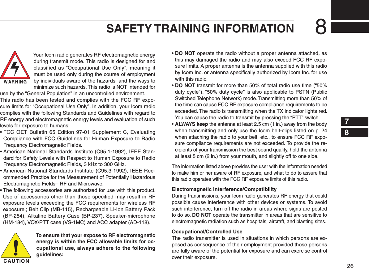
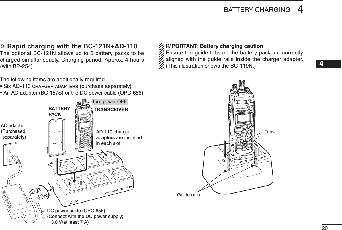
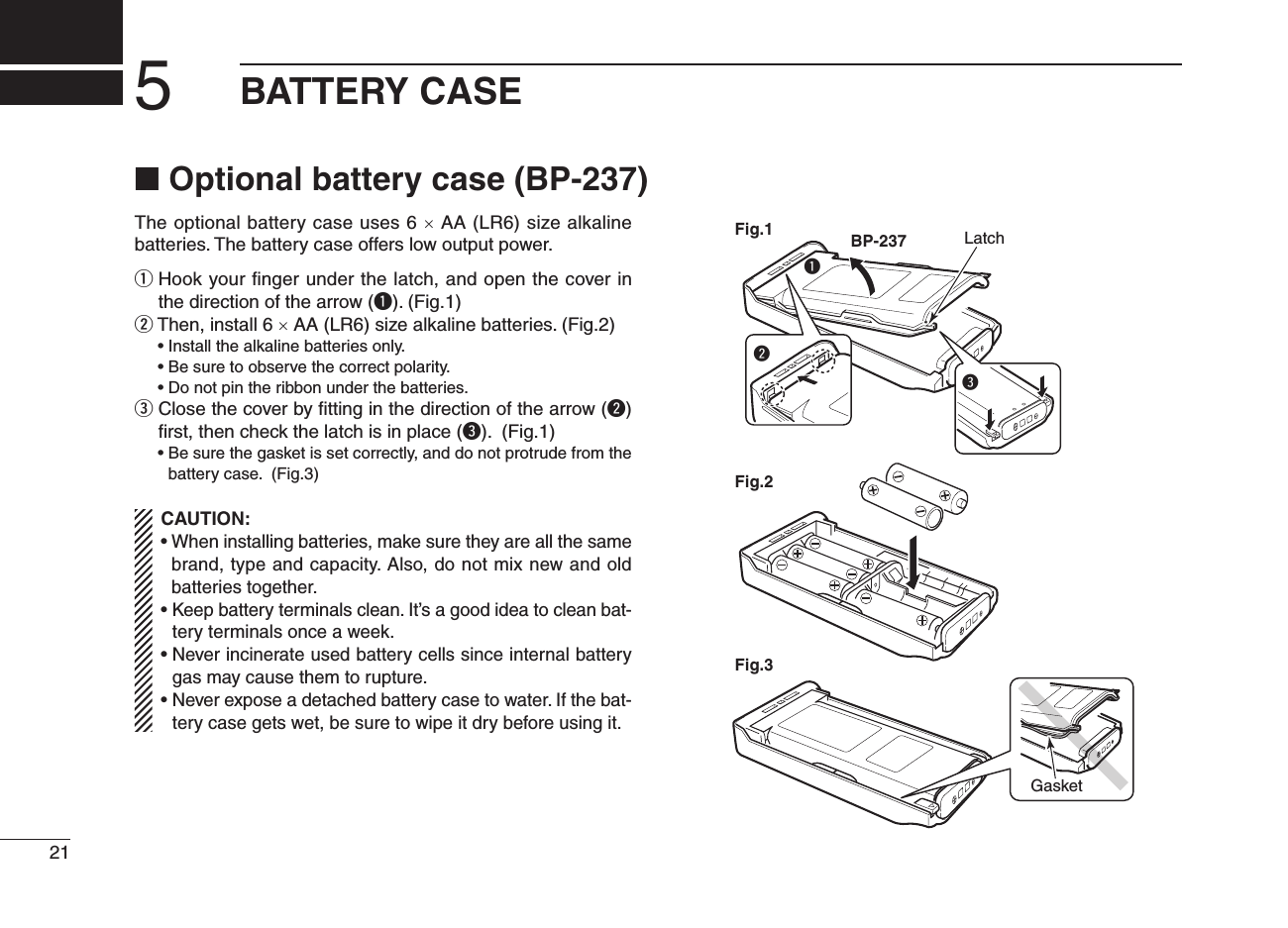
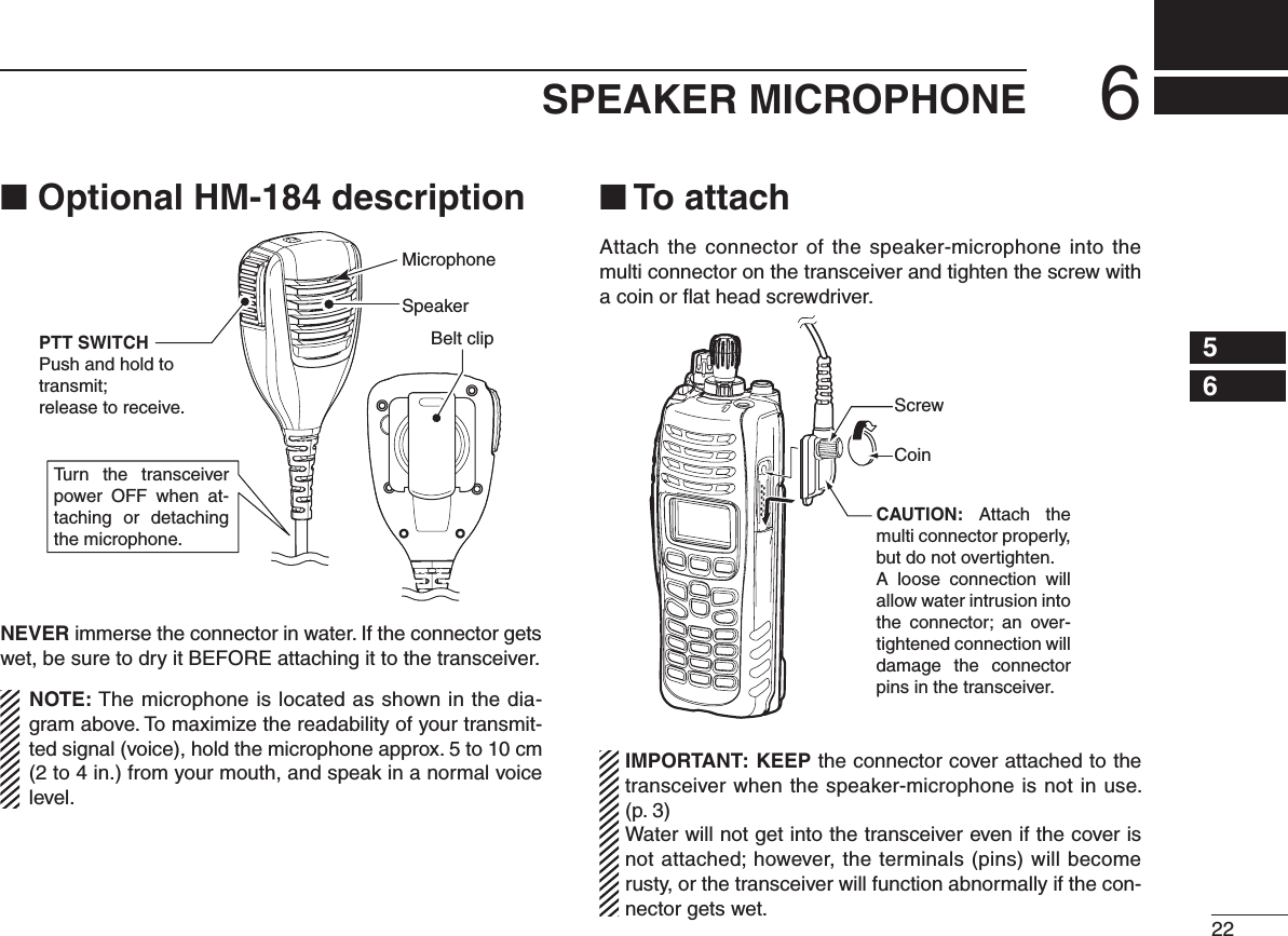
![iiiR DANGER! NEVER short the terminals of the bat-tery pack.R WARNING! NEVER hold the transceiver so that the antenna is very close to, or touching exposed parts of the body, especially the face or eyes, while transmitting. The transceiver will perform best if the microphone is 5 to 10 cm (2 to 4 in.) away from the lips and the transceiver is vertical.R WARNING! NEVER operate the transceiver with a headset or other audio accessories at high volume levels.CAUTION: NEVER use non-Icom battery packs/charg-ers to prevent the loss of the transceiver’s good performance and warranty.DO NOT push [PTT] when not actually desiring to transmit.DO NOT use or place the transceiver in direct sunlight or in areas with temperatures below –30°C (+22°F) or above +60°C (+140°F).The basic operations, transmission and reception of the transceiver are guaranteed within the specified operating temperature range. However, the LCD display may not oper-ate correctly, or show an indication in the case of long hours of operation, or after being placed in extremely cold areas.DO NOT modify the transceiver. The transceiver warranty does not cover any problems caused by unauthorized modi-fication.BE CAREFUL! The transceiver meets IP57 require-ments for dust-protection and waterproof protection. How-ever, once the transceiver has been dropped, dust-protection and waterproof protection cannot be guaranteed due to the fact that the transceiver may be cracked, or the waterproof seal damaged, etc.For U.S.A. onlyCAUTION: Changes or modifications to this transceiver, not expressly approved by Icom Inc., could void your author-ity to operate this transceiver under FCC regulations.Approved Icom optional equipment is designed for optimal performance when used with an Icom transceiver.Icom is not responsible for the destruction or damage to an Icom transceiver in the event it is used with equipment that is not manufactured or approved by Icom.PRECAUTIONS](https://usermanual.wiki/ICOM-orporated/307803.User-Manual/User-Guide-1312858-Page-4.png)
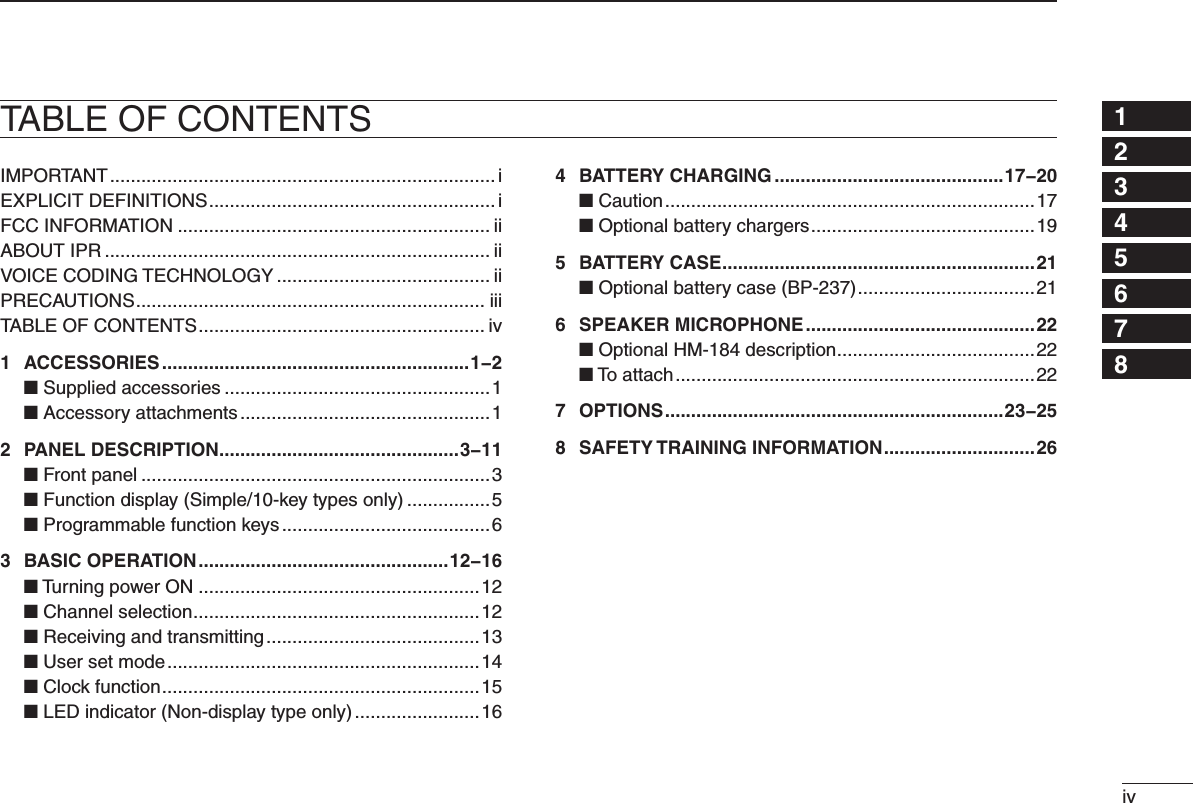
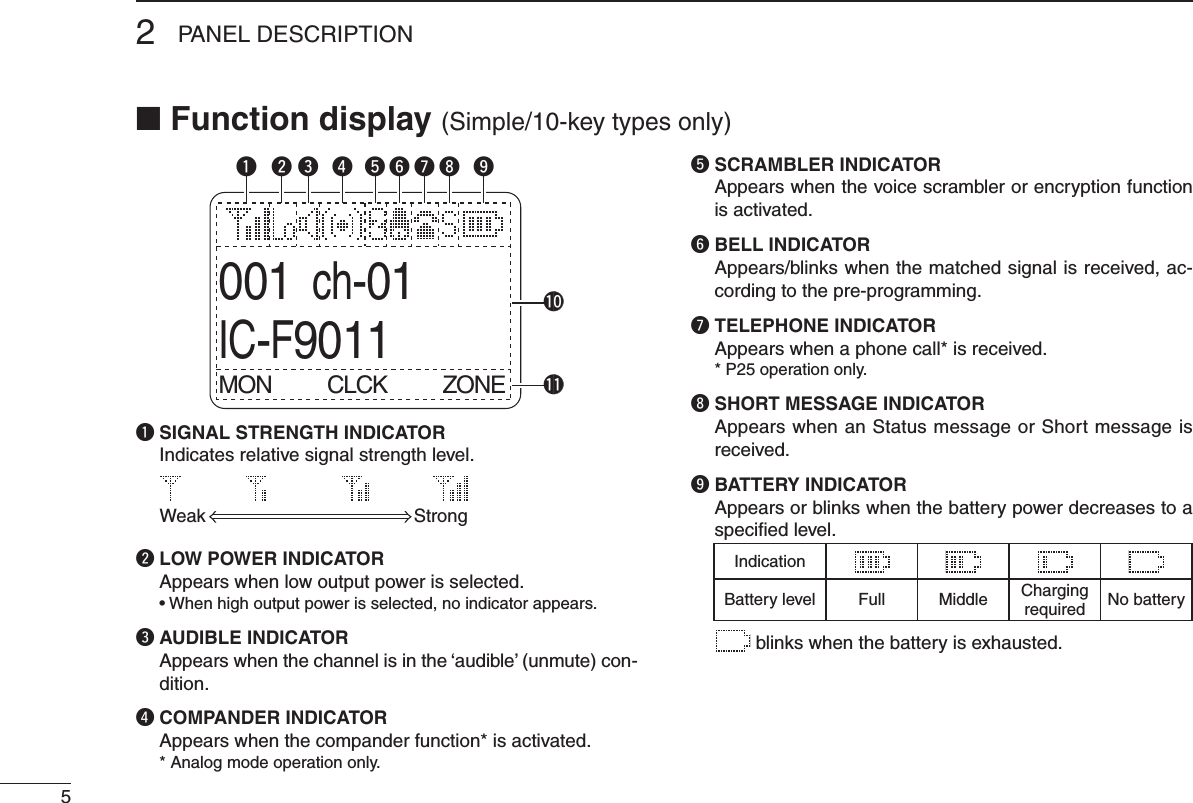
![■ Front panel*1 Simple/10-key types only*2 10-key type onlySpeakerMicrophoneFunction display*1(p. 5)!0*1!5o*1!1*2!2*1!4!3etyuirwqq ANTENNA CONNECTOR Connects the supplied antenna. (p. 1)w DEALER-PROGRAMMABLE KEY [EMR] Desired function can be programmed by your dealer. (p. 6) • [Emergency] is pre-programmed as default. (See the operating guide for details.)e LED INDICATOR ➥ Lights green while receiving a signal, or when the squelch is open. ➥ Lights red while transmitting. ➥ The LED indicator indicates some information. (Non-display type only) (p. 16)r DEALER-PROGRAMMABLE ABC SWITCH Desired function can be programmed to each position (A, B or C) independently by your dealer. (p. 11) To activate the pre-programmed function, set the white line of the ABC switch to the position A, B or C.When the white line of the ABC switch is set to the position C, the pre-programmed function at position C will be activated.White line32PANEL DESCRIPTION](https://usermanual.wiki/ICOM-orporated/307803.User-Manual/User-Guide-1312858-Page-8.png)
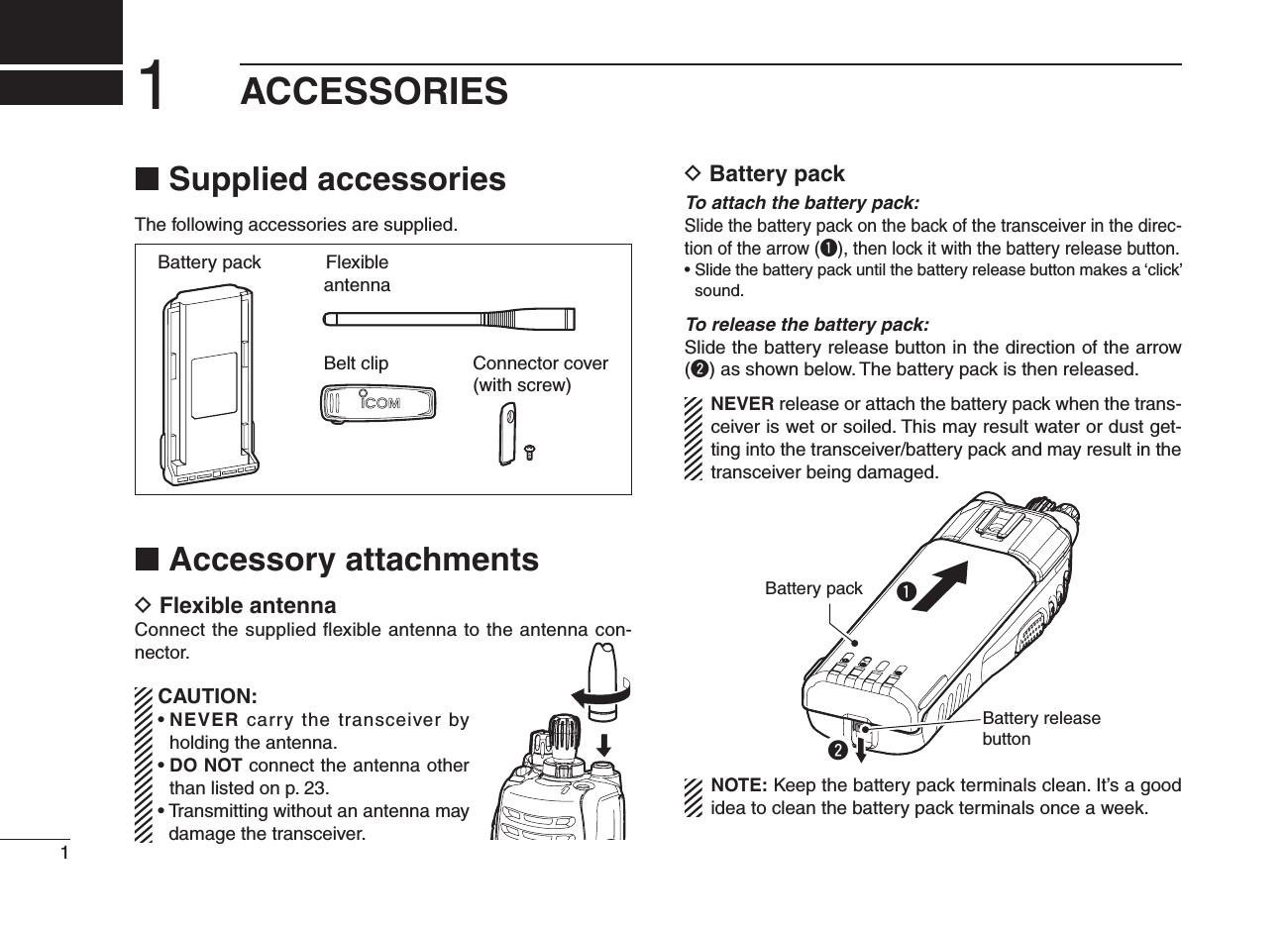
![42PANEL DESCRIPTION12345678910111213141516t CHANNEL INDICATOR ➥ Lights white according to the “Backlight” setting of the user set mode. ➥ When you rotate [Rotary selector] to select the channel or zone, set the desired channel/zone number to this point.y DEALER-PROGRAMMABLE TOGGLE SWITCH Desired function can be programmed by your dealer. (p. 11) When the toggle switch is set to the left side (‘ ’), the pre-programmed function will be activated.u VOLUME CONTROL [VOL] Rotate to turn the power ON/OFF and adjust the audio level.i ROTARY SELECTOR Rotate to select the pre-programmed memory channels or the operating zone. (Depending on the pre-setting) • The channel/zone that is positioned to the channel indicator (t) is selected as the operating channel/zone. • Depending on the pre-setting, selecting channel 1 using the ro-tary selector starts a scan. (Rotary Selector Home function)o DEALER-PROGRAMMABLE KEYS [I]/[II]/[III]/[Ω]/[≈]/[∫]/[√] (Simple/10-key types only) Desired function can be programmed independently by your dealer. (p. 6)!0 APP KEY [APP] (Simple/10-key types only) Desired function can be programmed by your dealer. (p. 6)!1 10-KEYPAD (10-key type only) The keypad allows you to enter digits to: • Select memory channels, tone channels and DTMF codes (while in the DTMF code channel selection mode.) • Start up with the password • Input the Individual ID code for digital operation. (Depending on the pre-setting)!2 HOME KEY [HOME] (Simple/10-key types only) Desired function can be programmed by your dealer. (p. 6) • [Home] is pre-programmed as default. (See p. 7 for details.)!3 PTT SWITCH [PTT] Push and hold to transmit; release to receive. • Depending on the pre-setting, when an external unit with its own PTT switch* is connected to the multi-connector, the transceiv-er’s [PTT] is disabled. * Such as an optional speaker-microphone or headset.!4 DEALER-PROGRAMMABLE KEYS [Side1]/[Side2]/[Side3] Desired function can be programmed independently by your dealer. (p. 6)!5 MULTI-CONNECTOR Connect optional equipment.Connector coverNOTE: Attach the connector cover when the optional equipment is not used. See p. 2 for details.](https://usermanual.wiki/ICOM-orporated/307803.User-Manual/User-Guide-1312858-Page-9.png)
![62PANEL DESCRIPTION12345678910111213141516!0 ALPHANUMERIC DISPLAY Displays an operating channel number, channel name, Set mode contents, DTMF code, etc.!1 KEY INDICATOR Indicate the programmed function of the front panel keys ([I], [II] and [III]).See the operating guide for details of Analog, MDC and P25 Trunking/Conventional system operations. Consult your Icom dealer or system operator for details concern-ing your transceiver’s programming.■ Programmable function keysThe following functions can be assigned to the following pro-grammable function keys and switches;[EMR], [Side1], [Side2], [Side3], [I]*, [II]*, [III]*, [Ω]*, [≈]*, [∫]*, [√]*, [APP]*, [HOME]*, ABC switch and Toggle switch.*Simple/10-key types onlyConsult your Icom dealer or system operator for details con-cerning your transceiver’s programming.If the key indicator shows the programmed function key name, push the front panel key ([I], [II] or [III]) under the key indicator to activate the programmed function.( The function key name in parentheses in the following expla-nation is displayed for that key indicator; e.g. “UP”)For Non-display type:The programmable key functions are limited and some key functions should be operated differently from Simple and 10-key types. (See pp. 8 and 9 for details.)For ABC and Toggle switches:The programmable key functions to ABC and Toggle switches are limited. (See p. 11 for details.)](https://usermanual.wiki/ICOM-orporated/307803.User-Manual/User-Guide-1312858-Page-11.png)
![72PANEL DESCRIPTIOND For All types (Common operation)PRIO A AND PRIO B KEYS “PRA” “PRB”Push to select Priority A or Priority B channel.MR-CH 1, MR-CH 2, MR-CH 3 AND MR-CH 4 KEYS“CH1” “CH2” “CH3” “CH4”Push to select the memory channels 1, 2, 3 and 4 directly.MONI KEY “MON”➥ Push to mute and release the CTCSS (DTCS), 2-tone, NAC or Talkgroup ID squelch mute. Open any squelch/de-activate any mute while pushing and holding this key. • Depending on the pre-setting, the ‘Audible’ (unmute) condition may automatically return to the ‘Inaudible’ (mute) condition, after a specified time period.➥ Depending on the pre-setting, pushing and holding this key for 1 sec. cancels the scan. LOCK KEY “LOCK”➥ Push and hold for 1 sec. to electronically lock all program-mable keys except the following: [PTT], [Moni], [Light], [Lock], [Emergency], [Surveillance] and [OPT 1/2/3].➥ Push and hold for 1 sec. again to turn the function OFF.LIGHT KEY “LIGT”Push to turn the transceiver’s backlight ON for about 5 sec. when the backlight function is turned OFF in user set mode. (p. 14)HOME KEY “HOME”Push to return to the stand-by mode.• After editing some information that requires to be memorized, push this key to save the editing contents in the memory before returning to the stand-by mode.OPT MOMENTARY KEYS “O1M” “O2M” “O3M”Push to control the output signal level from the optional unit connector.](https://usermanual.wiki/ICOM-orporated/307803.User-Manual/User-Guide-1312858-Page-12.png)
![82PANEL DESCRIPTION12345678910111213141516D For All types (Different operation with Non-display type)When the following key functions are programmed to Non-display type, the key functions may be limited and some key functions should be operated differently from Simple and 10-key types.HIGH/LOW KEY “H/L”Push to select the transmit output power temporarily or per-manently, depending on the pre-setting.• Ask your dealer for the output power level for each selection.• Emits one beep when Low 1 is selected, two beeps when Low 2 is selected and three beeps when High is selected. (Non-display type only)SCAN KEY “SCAN”❍ For Simple/10-key types➥ Push to start and cancel scanning operation. • When the Power ON Scan, Auto Scan, or Rotary Selector Home function starts a scan, push this key to cancel the scan. The canceled scan resumes after the specified time period has passed.➥ Push and hold this key for 1 sec. to indicate the scan list, then push [CH Up] or [CH Down] to select a desired list. (Depending on the presetting.)❍ For Non-display typePush to start and cancel scanning operation.• When the Power ON Scan, Auto Scan, or Rotary Selector Home function starts a scan, push this key to cancel the scan. The can-celed scan resumes after the specified time period has passed.• The LED indicator blinks green slowly while scanning.SURVEILLANCE KEY “SURV”When this function is turned ON, the beep is not emitted and the LCD backlight does not light when a signal is received or a key is pushed.❍ For Simple/10-key typesPush to turn the surveillance function ON or OFF.❍ For Non-display type➥ Push and hold for 1 sec. to turn the surveillance function ON.➥ When the surveillance function is ON, push to turn the function OFF.TALK AROUND KEY “TA” (Conventional operation only)The talk around function equalizes the transmit frequency to the receive frequency for transceiver-to-transceiver commu-nication.❍ For Simple/10-key typesPush to turn the talk around function ON or OFF.❍ For Non-display type➥ Push and hold for 1 sec. to turn the talk around function ON.➥ When the talk around function is ON, push to turn the function OFF.](https://usermanual.wiki/ICOM-orporated/307803.User-Manual/User-Guide-1312858-Page-13.png)
![2PANEL DESCRIPTION9PRIO A REWRITE AND PRIO B REWRITE KEYS“PRAR” “PRBR”❍ For Simple/10-key types➥ Push to select Priority A or Priority B channel.➥ Push and hold [Prio A (Rewrite)] or [Prio B (Rewrite)] for 1 sec. to rewrite the operating channel as the Priority A or Priority B channel.❍ For Non-display typePush to select Priority A or Priority B channel.COMPANDER KEY “COMP”The compander function reduces noise components from the transmitted audio to provide clear communication.❍ For Simple/10-key typesPush to toggle the compander function ON and OFF. ❍ For Non-display type➥ Push and hold for 1 sec. to turn the compander function ON.➥ When the compander function is ON, push to turn the function OFF.OPT OUT KEYS “OP1” “OP2” “OP3”❍ For Simple/10-key typesPush to control the output signal level from the optional unit connector.❍ For Non-display type➥ Push and hold for 1 sec. to control the output signal level from the optional unit connector.➥ When this key function is activated, push to deactivate the function.D For Simple/10-key types onlyFollowing key functions cannot be programmed to Non-dis-play types.CH UP AND DOWN KEYS “UP” “DOWN”➥ Push to select an operating channel. When [Rotary selec-tor] selection mode is “operating channel,” this function is not available.➥ Push to select a scan group after pushing and holding [Scan].ZONE KEY “ZONE”Push this key, then push [CH Up] or [CH Down] to select the desired zone. When [Rotary selector] selects “operating zone,” push this key to switch the range of selectable zones.What is “zone”?— Selected channels are assigned to a zone according to how they are to be used in a group. For example, ‘Staff A’ and ‘Staff B’ are assigned into a “Business” zone, and ‘John’ and ‘Cindy’ are assigned into a “Private” zone.USER SET MODE KEY “SET”➥ Push and hold for 1 sec. to enter user set mode. • During in the user set mode, push this key to select an item that is enabled by your dealer, and change the value or condition by pushing [CH Up] or [CH Down].➥ Push and hold this key for 1 sec. again to exit user set mode.User set mode is also available via the ‘Power ON func-tion.’ Refer to p. 14 also.](https://usermanual.wiki/ICOM-orporated/307803.User-Manual/User-Guide-1312858-Page-14.png)
![102PANEL DESCRIPTION12345678910111213141516CLOCK KEY “CLCK” Push to indicate the current time on the LCD. (p. 15)• While the current time is indicated, push and hold this key for 1 sec. to enter the time data edit mode.SCAN ADD/DEL (TAG) KEY “SCAD”➥ Push to add the selected channel to or delete it from the scan list. 1. Push to indicate the scan list, then push [CH Up] or [CH Down] to select the desired list. 2. Push to add the channel to or delete it from the select-ed scan list. 3. Push and hold for 1 sec. to exit the scan list selection mode.➥ While a scan is paused on a non-priority channel, push this key to delete the selected channel from the scan group. • Depending on the pre-setting, the deleted channel is added to the scan group again, after the scan is canceled. (Nuisance Delete function)MENU AND MENU ➤ KEYS( [Menu ] and [Menu ➤] can only be assigned to [Ω] and [≈], respectively.)The menu mode is available when either [Menu ] or [Menu ➤] is assigned to [Ω] or [≈].During menu mode, the pre-programmed menu items (up to 15) become effective with [I], [II] and [III] keys. Push [Menu ]/[Menu ➤] to switch the previous/next 3 menu items, and push [I], [II] or [III] to activate the programmed function.During menu modePush [Menu�]or [Menu�]Push [Menu�]or [Menu�]Push [Menu�] or [Menu�]001ch-01IC-F9011MON CLCK ZONE001ch-01IC-F9011LOCK LIGT SET001ch-01IC-F9011SCNA PRA CH1Menu items](https://usermanual.wiki/ICOM-orporated/307803.User-Manual/User-Guide-1312858-Page-15.png)
![2PANEL DESCRIPTION11D For ABC and Toggle switches onlyZONE SWITCHSelects the pre-programmed zone directly.PRIO A AND PRIO B SWITCHESSelects Priority A or Priority B channel.MR-CH 1, MR-CH 2, MR-CH 3 AND MR-CH 4 SWITCHESSelects the memory channels 1, 2, 3 and 4, directly.TALK AROUND SWITCH (Conventional operation only)Turns the talk around function ON and OFF.• The talk around function equalizes the transmit frequency to the receive frequency for transceiver-to-transceiver communication.LOCK SWITCHTurns the lock function ON and OFF.All programmable keys except the following are locked:[PTT], [Moni], [Light], [Lock], [Emergency], [Surveillance] and [OPT 1/2/3].HIGH/LOW SWITCHSelects the transmit output power temporarily.• Ask your dealer for the output power level for each selection.SURVEILLANCE SWITCHTurns the surveillance function ON or OFF.When this function is turned ON, the beep is not emitted and the LCD backlight does not light when a signal is received or a key is pushed, etc.COMPANDER SWITCHTurns the compander function ON and OFF. The compander function reduces noise components from the transmitted audio to provide clear communication.OPT MOMENTARY SWITCHESControls the output signal level from the optional unit con-nector.](https://usermanual.wiki/ICOM-orporated/307803.User-Manual/User-Guide-1312858-Page-16.png)
![123BASIC OPERATION12345678910111213141516■ Turning power ON• Prior to using the transceiver for the first time, the battery pack must be fully charged for optimum life and opera-tion. (p. 17)• When you use the transceiver for the first time, or after the transceiver has sat unused for a long time, make sure to check the date and time indication after turning the power ON. If the time and date are not correct, reset them. (p. 15)q Rotate [VOL] to turn the power ON.w If the transceiver is programmed for a start up password, input the digit codes as directed by your dealer. • 10-keypad can be used for password input depending on ver-sion. • The keys in the table below can be used for password input. • The transceiver detects numbers in the same block as identical. Therefore “01234” and “56789” are the same.KEYNUMBER 0549382716e When the “PASSWORD” indication does not clear after in-putting 6 digits, the input code number may be incorrect. Turn the power OFF and start over in this case.When you operate Non-display type, the password setting is not available.■ Channel selectionSeveral types of channel selections are available. Methods may differ according to your system set up.NOTE: Depending on the pre-setting, “EMPTY” appears on the LCD when selecting an empty channel (no fre-quency is programmed). (Simple/10-key types only)NON-ZONE TYPE:To select the desired operating channel:• Push [CH Up] or [CH Down].• Rotate [ROTARY SELECTOR]*. - Up to pre-programmed 16 channels can be selected.• Push one of [MR-CH 1] to [MR-CH 4]. ZONE TYPE:To select the desired zone:• Push [Zone], then push [CH Up] or [CH Down].• Rotate [ROTARY SELECTOR]*. - Up to pre-programmed 16 zones can be selected.AUTOMATIC SCAN TYPE:Channel setting is not necessary for this type. When turn-ing power ON, the transceiver automatically starts scanning. Scanning stops when receiving a call.* Depending on the pre-setting. When [Rotary selector] selects “Operating channel,” [CH Up]/[CH Down] are not available, and when [Rotary selector] selects “Oper-ating zone,” [Zone]/[Zone Up]/ [Zone Down] are not available.](https://usermanual.wiki/ICOM-orporated/307803.User-Manual/User-Guide-1312858-Page-17.png)
![■ Receiving and transmittingNOTE: Transmitting without an antenna may damage the transceiver. See p. 1 for accessory attachments.Receiving:q Rotate [VOL] to turn the power ON.w Push [CH Up] or [CH Down], or rotate [ROTARY SELEC-TOR]* to select a channel, in sequence. *Depending on the pre-setting.e When receiving a call, adjust the audio output level to a comfortable listening level.Transmitting:Wait for the channel to become clear to avoid interference.q While pushing and holding [PTT], speak into the micro-phone at a normal voice level.w Release [PTT] to return to receive.IMPORTANT: To maximize the audio quality of your signal; 1. Pause briefly after pushing [PTT]. 2. Hold the microphone 5 to 10 cm (2 to 4 in.) from your mouth, then speak into the microphone at a normal voice level.D Transmitting notes• Transmit inhibit function The transceiver has several inhibit functions which restrict transmission under the following conditions:- The channel is in mute condition (‘Inaudible’ condition; “ ” does not appear.)- The channel is busy.- Un-matched (or matched) CTCSS is received. (Depending on the pre-setting.)- Un-matched (or matched) NAC is received*. (Depending on the pre-setting.) *Digital mode operation only.- The selected channel is a ‘receive only’ channel.• Time-out timer After continuous transmission for the pre-programmed time period, the time-out timer is activated, causing the trans-ceiver to stop transmitting.• Penalty timer Once the time-out timer is activated, transmission is further inhibited for a period determined by the penalty timer.133BASIC OPERATION](https://usermanual.wiki/ICOM-orporated/307803.User-Manual/User-Guide-1312858-Page-18.png)
![143BASIC OPERATION12345678910111213141516■ User set modeThe user set mode is accessed at power ON and allows you to set seldom-changed settings. You can “customize” the trans-ceiver operation to suit your preferences and operating style.When you operate Non-display type, this function is not available.Entering the user set mode:q While pushing and holding [I] and [II], rotate [VOL] to turn the power ON. • Turn power OFF in advance. • “SET MODE” appears for 1 sec. at power ON.w Push and hold [Ω] to enter user set mode. e Push [Ω] several times to select the appropriate item. Then push [∫] or [√] to set the desired level/condition. • Available set mode functions are Backlight, LCD contrast, Beep, Beep Level, Ringer Level, SQL Level, AF Min Level, Mic Gain, VOX Gain*, VOX Delay*, Horn, Battery Voltage, Signal Moni, Lone Worker and System info. * Appears only when the external VOX unit is connected.r Push and hold [Ω] again to exit the user set mode.User set mode is also available using a programmable key. Refer to p. 9 [User Set Mode] section for instructions regard-ing using the key assigned for user set mode.[User Set Mode] allows for quick item selection. Set “Enable” for the often used items with the CS-F9010/F9510 cloning sfotware. Ask your dealer for details.NOTE: While in the user set mode, [Ω], [∫] and [√] acti-vate regardless of the assigned key functions.[VOL][I]/[II][Ω][Ω][∫]/[√]](https://usermanual.wiki/ICOM-orporated/307803.User-Manual/User-Guide-1312858-Page-19.png)
![3BASIC OPERATION15■ Clock functionThe transceiver indicates the current time and date when [Clock] is pushed. And you can change the indication format and time/date settings.When you operate Non-display type, this function is not available.When you use the transceiver for the first time, or after the transceiver has sat unused for a long time, make sure to check the date and time indication after turning the power ON. If the time and date are not correct, reset them. (See ‘Time and date settings’ to the right.)D Time and date indicationq Push [Clock] to indicate the current time and date on the LCD. • When the indication format is set to 12-hour, “AM” or “PM” is indicated. • The LCD indication returns to the stand-by mode after 30 sec. has passed with no operation.12HR12:00PMYMD08-04-01MON CLCK ZONEDate indication format (Y: Year, M: Month, D: Day) The time indication format (12-hour/24-hour)TimeDatew Push [Clock] again to return to the stand-by mode.D Time and date settingsq Push [Clock] to indicate the current time and date on the LCD.12HR12:00PMYMD08-04-01MON CLCK ZONEw Push and hold [Clock] for 1 sec. to enter the time and date setting mode. • The time indication format, “24HR” or “12HR” blinks.12HR12:00PMYMD08-04-01MON CLCK ZONEe Push [Clock] to select the desired item to be changed.](https://usermanual.wiki/ICOM-orporated/307803.User-Manual/User-Guide-1312858-Page-20.png)
![163BASIC OPERATION12345678910111213141516r Push [CH Up] or [CH Down] to set the selected item.12HR03:00PMYMD08-04-01MON CLCK ZONEt Push [Clock] to set. • The next item blinks.12HR03:00PMYMD08-04-01MON CLCK ZONEy Repeat steps e to t to set items.u After setting, push and hold [Clock] for 1 sec. to program. • Return to the time and date setting mode.i Push [Clock] to return to the stand-by mode.■ LED indicator (Non-display type only)The LED indicator indicates some information as follows;(Ref.; R=Red, G=Green, O=Orange)• TX: Lights Red while transmitting a signal.TX Low BATT1O O G G G G G GG G G G G G G G R G R G R G R G R G R G R G R GR O R O R O R O R O R O R O R O G G G Clone ErrClone TX/RXLow BATT2Low BATT1Inh & Blank CHBusyF/S ScanCall LED BlinkCall LED ONTX Low BATT2TX R*R* R*R* R* R*R*O* Lights (or blinks) orange when the optional battery case is at-tached.• TX low BATT1: TX is performed at Low BATT1.• TX low BATT2: Low BATT2 was detected during TX mode.• Fast/Slow scan: Blinks while Fast/Slow scan is activated.• RX: Turns Green while receiving a signal.• Low BATT1: You should charge the battery. (blinks slowly)• Low BATT2: You must charge the battery. (blinks fast)• CH err: Non-programmed channel is selected.](https://usermanual.wiki/ICOM-orporated/307803.User-Manual/User-Guide-1312858-Page-21.png)
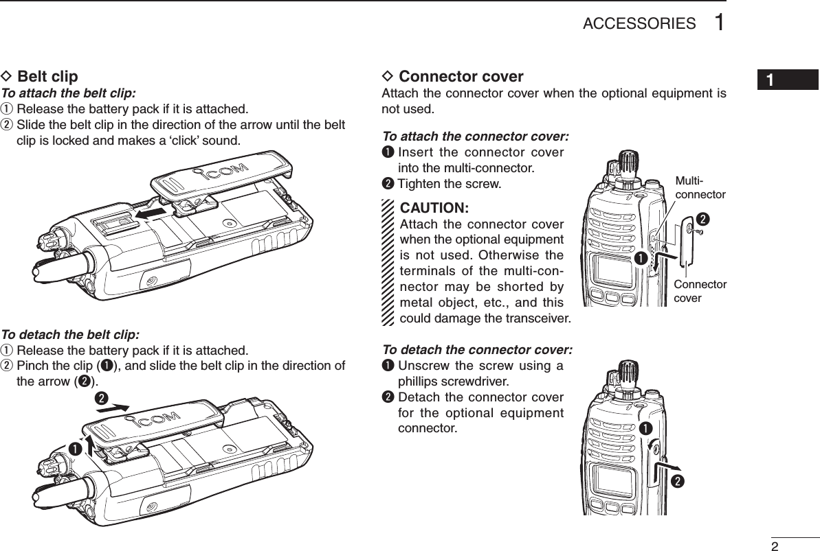
![257OPTIONSD About VS-1MC vox/ptt case (Continued)VOX gain and delay adjustmentq Attach the connector of the VS-1MC into the multi-connec-tor on the transceiver and tighten the screw. • Toggle the VOX/PTT select switch to [VOX].w Enter user set mode. (p. 14)e Push [Ω] several times to select the “VOX Gain” or “VOX Delay” items. Then, push [∫] or [√] to set the desired level/condition.r Push and hold [Ω] again to exit the user set mode. • Until turning power OFF, [Ω], [∫] and [√] is not activated as the assigned key function.These adjustments are for Simple/10-key types only.• VOX GainThe VOX sensitivity level can be adjusted from OFF or 1 to 6 (more sensitive).VOX GAIN 3MON CLCK ZONEVOX OFFMON CLCK ZONEPush[∫] or [√]VOX function is OFF VOX gain level 3(default)• VOX DelayThe VOX delay time can be set from 0.5 to 3.0 sec. (0.5 sec. step) for a convenient interval before returning to receive.VOX DLY3.0MON CLCK ZONEVOX DLY0.5MON CLCK ZONE0.5 sec (min.)(default)3.0 sec (max.)Push[∫] or [√]If your voice is detected, “TX” appears on the LCD as shown below during the VOX gain or VOX delay adjust-ment. (The transmission is not performed.)VOX GAIN 3TX MON CLCK ZONEVOX DLY3.0TXMON CLCK ZONEAppearVOX gain adjustment VOX delay adjustmentNOTE: MIC/VOX gain can be adjusted via the Adjusting pot using a thin screw driver.](https://usermanual.wiki/ICOM-orporated/307803.User-Manual/User-Guide-1312858-Page-30.png)