ICOM orporated 312002 UHF Transceiver User Manual
ICOM Incorporated UHF Transceiver
UserManual.wiki
>
ICOM orporated
>
312002 User Manual
User Manual
Navigation menu
Upload a User Manual
Namespaces
Wiki Guide
HTML
PDF
Info
Views
User Manual
Discussion / Help
Navigation

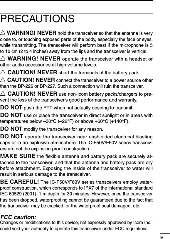
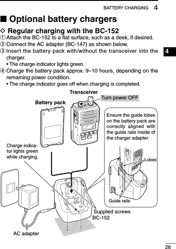
![1ACCESSORIES1■ Supplied accessoriesBattery packAntennaBelt clipKey sticker*Jack cover* There are no names on the programmable function keys since the functions can be freely assigned to [P0] to [P3], [Red], [ ] and [ ] keys. Attach the supplied key stickers above the appropriate keys for easy recognition of that key’s assigned function.](https://usermanual.wiki/ICOM-orporated/312002/User-Guide-926366-Page-8.png)
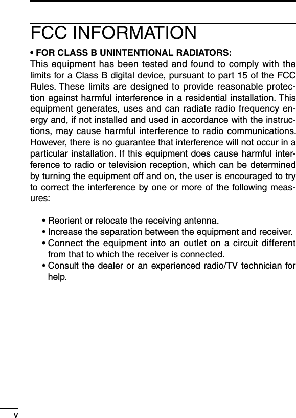
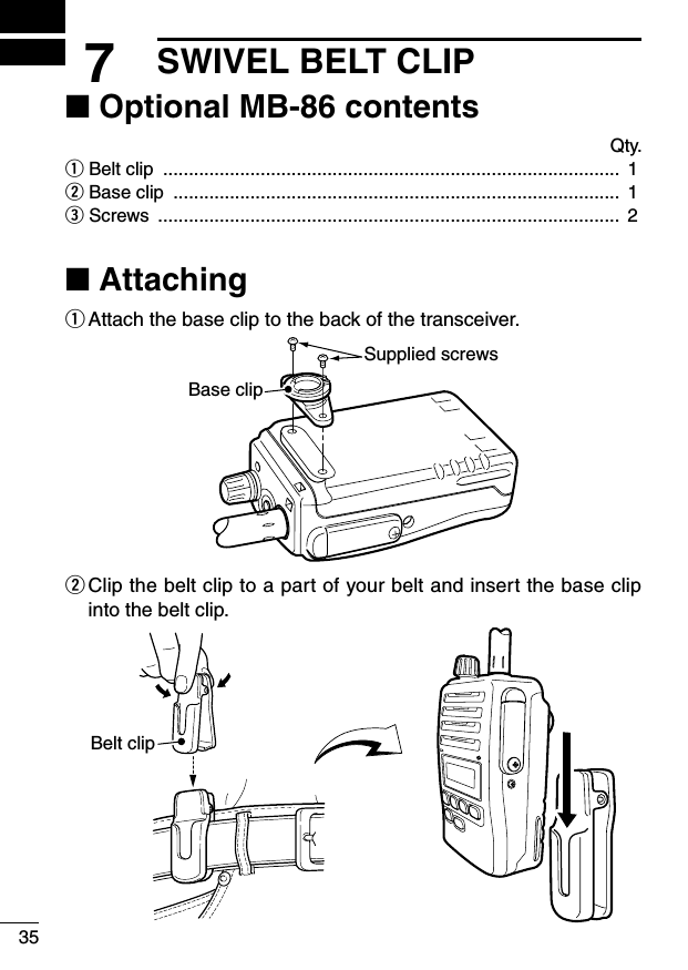
![31ACCESSORIESD Jack cover Attach the jack cover when the optional equipment is not used.To attach the jack cover:q Insert the jack cover into the [SP MIC] jack.w Tighten the screw.To detach the jack cover:e Unscrew the screw using a phillips screwdriver.r Detach the jack cover for the optional equipment connection.D Belt clipAttach the belt clip to the back of the transceiver with the supplied screws.Supplied screwswJack cover[SP MIC] jackScrewqer](https://usermanual.wiki/ICOM-orporated/312002/User-Guide-926366-Page-10.png)
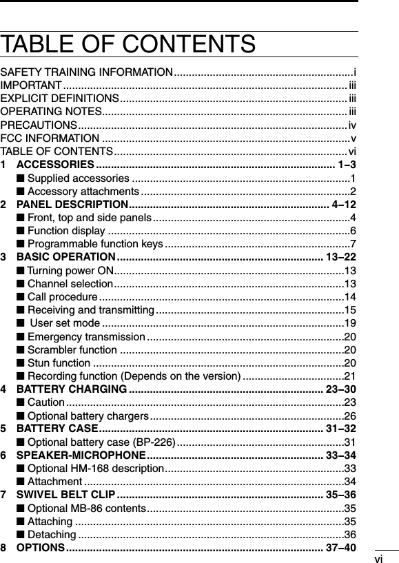
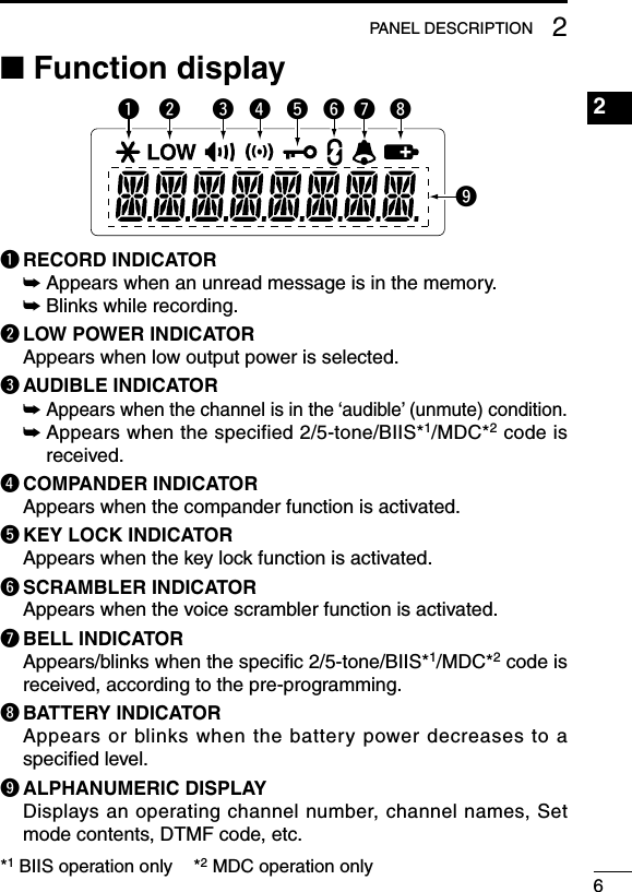
![42PANEL DESCRIPTION1234567891011121314151617181920■ Front, top and side panelsq VOLUME CONTROL [VOL] Turns power ON and adjusts the audio level.w RED BUTTON The desired function can be assigned by your dealer. (p. 7)e ANTENNA CONNECTOR Connects the supplied antenna. (p. 2)MicrophoneFunction display(p. 6)wertyuqiSpeaker](https://usermanual.wiki/ICOM-orporated/312002/User-Guide-926366-Page-11.png)
![52PANEL DESCRIPTIONr EXTERNAL SPEAKER-MICROPHONE JACK [SP MIC] Connects the optional speaker-microphone, etc.[SP MIC] jack coverNOTE: KEEP the [SP MIC] jack cover attached to the transceiver when the optional equipment is not used. (See p. 3 for details)t DEALER-PROGRAMMABLE KEYS [P0] to [P3] The desired functions can be assigned independently by your dealer. (p. 7)y CH UP AND DOWN KEYS [ ]/[ ] Push to select an operating channel, etc.* Desired functions can be assigned independently by your dealer. (p. 7)u TRANSMIT/BUSY INDICATOR Lights red while transmitting; lights green while receiving a signal, or when the squelch is open.i PTT SWITCH [PTT] ➥ Push and hold to transmit; release to receive. ➥ When the recording function is activated, TX voice message can be recorded while pushing and holding [PTT]. (p. 21)](https://usermanual.wiki/ICOM-orporated/312002/User-Guide-926366-Page-12.png)
![72PANEL DESCRIPTION■ Programmable function keysThe following functions can be assigned to [P0], [P1], [P2], [P3], [Red], [ ] and [ ] programmable function keys. Consult your Icom dealer or system operator for details concern-ing your transceivers programming.If the programmable function names are bracketed in the following explanations, the specific key is used to activate the function de-pends on programming.CH UP AND DOWN KEYS➥Push to select an operating channel.➥ Push to select a transmit code channel after pushing [TX Code CH Select].➥ Push to select a DTMF channel after pushing [DTMF Autodial].➥ Push to select a scan group after pushing and holding [Scan A Start/Stop]/[Scan B Start/Stop].ZONE SELECT KEYPush this key, then select the desired zone using [CH Up]/[CH Down].What is a “zone”?—The desired channels are assigned into a zone according to the intended use for grouping. For example, ‘Staff A’ and ‘Staff B’ are assigned into a “Business” zone, and ‘John’ and ‘Cindy’ are assigned into a “Private” zone.SCAN A START/STOP KEY➥ This key’s operation depends on the Power ON Scan setting. When the power ON scan function is turned OFF; Push to start and cancel scanning operation. When the power ON scan function is turned ON; Push to pause scanning, then resumes scanning after a speci-fied time period has passed. ➥ Push and hold this key for 1 sec. to indicate the scan group, then select the desired scan group using [CH Up]/[CH Down].](https://usermanual.wiki/ICOM-orporated/312002/User-Guide-926366-Page-14.png)
![82PANEL DESCRIPTION2SCAN B START/STOP KEY➥ Push to start and cancel scanning operation. Scan resumes after a specified time period has passed when scan is cancelled except for this key. ➥ Push and hold this key for 1 sec. to indicate the scan group, then select the desired scan group using [CH Up]/[CH Down].SCAN ADD/DEL (TAG) KEY➥ Push to add or delete the selected channel to/from the scan group. 1. Push to indicate the scan group, then push [CH Up] or [CH Down] to select the desired group. 2. Push to add or delete the channel to/from the selected scan group. 3. Push and hold for 1 sec. to exit the scan group selection mode.➥ Push this key while scan is paused (a signal is detected) on a channel (except for priority channel,) the channel is cleared from the scan group. Depending on the setting, the cleared channel is added to the scan group again after the scan is cancelled. (Nuisance Delete function)PRIORITY CHANNEL KEYS➥ Push to select Priority A or Priority B channel.➥ Push and hold [Prio A (Rewrite)] or [Prio B (Rewrite)] to set the operating channel as the Priority A or Priority B channel.MR-CH 1/2/3/4 KEYSPush to select the memory channel 1 to 4 directly.LOCK KEYPush and hold to toggle the key lock function ON or OFF.• All programmable keys except the followings are electronically locked when the key lock function is activated: [PTT], [Light], [Lone Worker], [Sur-veillance], [Call] (incl. Call A and Call B), [Moni(Audi)] and [Emergency].](https://usermanual.wiki/ICOM-orporated/312002/User-Guide-926366-Page-15.png)
![92PANEL DESCRIPTIONMONITOR KEY ➥ Mute and release the CTCSS (DTCS) or 2-tone squelch mute. Open any squelch/deactivate any mute while pushing and hold-ing this key. (LMR operation only)➥ Activates one of (or two of) the following functions on each channel independently: (PMR operation only) • Push and hold to un-mute the channel (audio is emitted; ‘Audible’ condition). • Push to mute the channel (sets to ‘Inaudible’ only). • Push after the communication is finished to send a ‘reset code’. (BIIS operation only) NOTE: The un-mute condition (‘Audible’ condition) may auto-matically return to the mute condition (‘Inaudible‘ condition) after a specified period.LIGHT KEYPush to turn the backlight ON for about 5 sec. even if the backlight function is turned OFF in user set mode.LONE WORKER KEYPush to turn the Lone Worker function ON or OFF.• If the Lone Worker function is activated, the Emergency function is automatically turned ON after the specified time period has passed with no operation is performed.HIGH/LOW KEYPush to select the transmit output power temporarily or perma-nently, depending on the pre-setting.• Ask your dealer for the output power level for each selection.C.TONE CHANNEL ENTER KEYPush to enter the continuous tone channel selection mode, and push [CH Up]/[CH Down] to change the tone frequency/code set-ting. The selected channel remains set as the continuous tone channel until another channel is designated as such.](https://usermanual.wiki/ICOM-orporated/312002/User-Guide-926366-Page-16.png)
![102PANEL DESCRIPTION2TALK AROUND KEYPush to turn the talk around function ON and OFF.• The talk around function equalizes the transmit frequency to the re-ceive frequency for transceiver-to-transceiver communication.WIDE/NARROW KEYPush to toggle the IF bandwidth between wide and narrow.• The wide passband width can be selected from 25.0 or 20.0 kHz using the CS-F50V cloning software. (PMR operation only) Ask your dealer for details.DTMF AUTODIAL KEY➥ Push to enter the DTMF channel selection mode. Then select the desired DTMF channel using [CH Up]/[CH Down].➥ After selecting the DTMF channel, push again to transmit the selected DTMF code.DTMF RE-DIAL KEYPush to transmit the last-transmitted DTMF code.• TX memories are cleared after turning the transceiver OFF.CALL KEYSPush to transmit a 2/5-tone/BIIS ID code.• Call transmission is necessary before calling another station depend-ing on your signalling system.• [Call A] and/or [Call B] may be available when your system employs selective ‘Individual/Group’ calls. Ask your dealer which call is as-signed to each key.SURVEILLANCE KEYPush to turn the surveillance function ON or OFF.When this function is turned ON, the beep is not emitted and the LCD backlight and the LED indicator do not light when a signal is received or a key is pushed.](https://usermanual.wiki/ICOM-orporated/312002/User-Guide-926366-Page-17.png)
![112PANEL DESCRIPTIONEMERGENCY KEYSPush and hold to transmit the emergency call.• The emergency call transmits with beeps; the display does not change.• The transceiver can transmit the emergency call silently or with the display changes depending on the pre-setting. Ask your dealer for details.• If you want to cancel the emergency call, push and hold the key again before transmitting the call.• The emergency call is transmitted one time only or repeatedly until receiving a control code, depending on the pre-setting.TX CODE ENTER KEY (PMR operation only)Push to enter the TX code edit mode. Then set the desired digit using [CH Up]/[CH Down]. (p. 18)TX CODE CHANNEL SELECT KEY➥ Push to enter the TX code channel selection mode. Then select the desired channel using [CH Up]/[CH Down]. (p. 17)➥ While in the TX code channel selection mode, push and hold for 1 sec. to enter the TX code edit mode. Then set the desired digit using [CH Up]/[CH Down]. (p. 17; PMR operation only)TX CODE CHANNEL UP/DOWN KEYSPush to select a TX code channel directly.ID-MR SELECT KEY (PMR operation only)➥ Recalls detected ID codes. • Push this key, then push [CH Up]/[CH Down] for selection. • Up to 5 ID’s are memorized.➥ Push and hold to erase the selected memorized ID’s.VOICE SCRAMBLER FUNCTIONPush to turn the voice scrambler function ON and OFF.](https://usermanual.wiki/ICOM-orporated/312002/User-Guide-926366-Page-18.png)
![122PANEL DESCRIPTION1234567891011121314151617181920COMPANDER KEYPush to turn the compander function ON and OFF. The compander function reduces noise components from the transmitting audio to provide clearer communication.USER SET MODE KEY➥Push and hold to enter user set mode. • While in user set mode, push this key to select an item, and push [CH Up]/[CH Down] to change the value or condition.➥Push and hold this key again to exit user set mode. • User set mode is also available via the ‘Power ON function’. Please refer to p. 19 also.PLAYBACK KEY (p. 22)➥Push to playback the recorded messages in sequence, starting with the latest one. • A short beep is emitted after playing back each message. • A long beep is emitted after playing back all messages. • An error beep is emitted when there are no messages in the memory.➥While playing back the message, push and hold for 1 sec. to delete the selected message.PLAYBACK/REC KEY (pgs. 21, 22)➥Push to playback the recorded messages in sequence, starting with the latest one. • A short beep is emitted after playing back each message. • A long beep is emitted after playing back all messages. • “NO REC” is displayed when no message is in the memory.➥Push and hold for 1 sec. to start recording. Push again to stop recording.➥While playing back the message, push and hold for 1 sec. to delete the selected message.](https://usermanual.wiki/ICOM-orporated/312002/User-Guide-926366-Page-19.png)
![133BASIC OPERATION■ Turning power ONq Rotate [VOL] to turn power ON. • When the opening vibration function is turned ON, the transceiver vibrates for 2 sec. Ask your dealer for details.w If the transceiver is programmed for a start up passcode, input digit codes as directed by your dealer. • The keys in the table below can be used for password input: • The transceiver detects numbers in the same block as identical. Therefore “01234” and “56789” are the same.KEYNUMBER 0549382716ore When the “PASSWORD” indication does not clear after input-ting 4 digits, the input code number may be incorrect. Turn the power off and start over in this case.■ Channel selectionSeveral types of channel selections are available. Methods may differ according to your system set up.NON-ZONE TYPE:Push [CH Up]/[CH Down] to select the desired operating channel in sequence; or, push one of [MR-CH 1] to [MR-CH 4] to select a channel directly.ZONE TYPE:Push [Zone] then push [CH Up]/[CH Down] to select the desired zone.AUTOMATIC SCAN TYPE:Channel setting is not necessary for this type. When turning the power ON, the transceiver automatically starts scanning. Scanning stops when receiving a call.](https://usermanual.wiki/ICOM-orporated/312002/User-Guide-926366-Page-20.png)
![143BASIC OPERATION1234567891011121314151617181920■ Call procedureWhen your system employs tone signalling (excluding CTCSS and DTCS), this call procedure may be necessary prior to voice trans-mission. The tone signalling employed may be a selective calling system which allows you to call specific station(s) only and prevent unwanted stations from contacting you.q Select the desired TX code channel or 2/5-tone code according to your System Operator’s instructions. • This may not be necessary depending on programming. • Refer to pgs. 17, 18 for selection.w Push [Call] (assigned to one of the dealer programmable keys).e After transmitting, the remainder of your communication can be carried out in the normal fashion.Selective calling Non-selective calling](https://usermanual.wiki/ICOM-orporated/312002/User-Guide-926366-Page-21.png)
![153BASIC OPERATION■ Receiving and transmitting NOTE: Transmitting without an antenna may damage the trans-ceiver. See p. 2 for antenna attachment.Receiving:q Rotate [VOL] to turn power ON.w Push [CH Up] or [CH Down] to select a channel.e When receiving a call, adjust the audio output level to a com-fortable listening level.Transmitting:Wait for the channel to become clear to avoid interference.q While pushing and holding [PTT], speak into the microphone at a normal voice level. • When a tone signalling system is used, the call procedure de-scribed at the previous page may be necessary.w Release [PTT] to return to receive. IMPORTANT: To maximize the readability of your signal; 1. Pause briefly after pushing [PTT]. 2. Hold the microphone 5 to 10 cm (2 to 4 inches) from your mouth, then speak into the microphone at a normal voice level.](https://usermanual.wiki/ICOM-orporated/312002/User-Guide-926366-Page-22.png)
![163BASIC OPERATION3D Receiving note• Vibration function (Depends on the version)When the matched RX code signal is received, the transceiver may vibrate for a specified time period, depending on the pre-setting. Push any key or [PTT] to stop the vibration. NOTE: • The transceiver cannot stop the vibration suddenly after push-ing any key or [PTT]. • The vibration sound may be heard at the communication party, or be recorded if the recording function is activated when [PTT] is pushed to stop the vibration.D Transmitting notes• Transmit inhibit functionThe transceiver has several inhibit functions which restrict trans-mission under the following conditions:- The channel is in mute condition (‘Inaudible’ condition; “ ” does not appear).- The channel is busy.- Un-matched (or matched) CTCSS is received. (Depending on the pre-setting)- The selected channel is a ‘receive only’ channel.• Time-out timerAfter continuous transmission for the pre-programmed time period, the time-out timer starts, causing the transceiver to stop transmit-ting.• Penalty timerOnce the time-out timer starts, transmission is further inhibited for a period determined by the penalty timer.](https://usermanual.wiki/ICOM-orporated/312002/User-Guide-926366-Page-23.png)
![173BASIC OPERATIOND TX code channel selectionIf the transceiver has [TX Code CH Select] assigned to it, the in-dication can be toggled between the operating channel number (or name) and TX code channel number (or name). When the TX code channel number (or name) is displayed, [CH Up] or [CH Down] selects the TX code channel.USING [TX CODE CH SELECT] KEY:q Push [TX Code CH Select]— a TX code channel number (or name) appears.w Push [CH Up] or [CH Down] to select the desired TX code channel.e After selecting, push [TX Code CH Select] to set. • Return to the stand-by mode.r Push [Call] to transmit the selected TX code.USING [TX CODE CH UP]/[TX CODE CH DOWN] KEY:If the transceiver has a [TX Code CH Up] or [TX Code CH Down] key assignment, the programmed TX code channel can be se-lected directly when pushed.D TX code number edit (PMR operation only)If the transceiver has [TX Code CH Select] or [TX Code Enter] as-signed to it, TX code contents can be edited within the allowable digits.USING [TX CODE CH SELECT] KEY:q Push [TX Code CH Select] to enter the TX code channel selec-tion mode. • Select the desired operating channel before entering the TX code channel selection mode if necessary.w Push [TX Code CH Select] for 1 sec. to enter the TX code edit mode. • The digit to be edited blinks.](https://usermanual.wiki/ICOM-orporated/312002/User-Guide-926366-Page-24.png)
![183BASIC OPERATION3e Push [TX Code CH Select] to select the desired digit to be ed-ited.r Push [CH Up]/[CH Down] to select the desired digit.t Push [TX Code CH Select] to set. The digit to the right will blink automatically.y Repeat r and t to edit all allowable digits.u After editing, push [TX Code CH Select] to set. • Return to the stand-by mode.i Push [Call] to transmit.USING [TX CODE ENTER] KEY:q After pushing [TX Code CH Select], push [CH Up] or [CH Down], or push [TX Code CH Up] or [TX Code CH Down] to se-lect the desired TX code channel.w Push [TX Code Enter] to enter the TX code edit mode. • The digit to be edited blinks.e Push [TX Code Enter] to select the desired digit to be edited.r Push [CH Up]/[CH Down] to select the desired digit.t Push [TX Code Enter] to set. The digit to the right will blink au-tomatically.y Repeat r and t to edit all allowable digits.u After editing, push [TX Code Enter] to set. • Return to the stand-by mode.i Push [Call] to transmit.D DTMF transmissionIf the transceiver has [DTMF Autodial] assigned to it, the automatic DTMF transmission function is available. Up to 8 DTMF channels are available.q Push [DTMF Autodial]— a DTMF channel appears.w Push [CH Up] or [CH Down] to select the desired DTMF channel.e Push [DTMF Autodial] to transmit the DTMF code to the se-lected DTMF channel.](https://usermanual.wiki/ICOM-orporated/312002/User-Guide-926366-Page-25.png)
![193BASIC OPERATION■ User set modeUser set mode is accessed at power ON and allows you to set seldom-changed settings. You can “customize” the transceiver op-eration to suit your preferences and operating style.Entering the user set mode:q While pushing and holding [ ] and [ ], rotate [VOL] to power ON. • Turn power OFF in advance. • “SET MODE” appears for 1 sec.w Push and hold [P0] for 1 sec. to enter user set mode.e Push [P0] momentarily to select the appropriate item. Then push [ ] or [ ] to set the desired level/condition. • Available set mode functions are Backlight, Beep, SQL Level, Ringer Level, AF Min level, Mic Gain, VOX Gain*, VOX Delay*, Battery Voltage, Signal Moni, Vibration and Lone Worker.r Push and hold [P0] again to exit set mode.* Appears when the optional headset is connected.User set mode is also available using a programmable key. Please refer to p. 12 [User Set Mode] section for instructions regarding using the key assigned for user set mode. NOTE: [ ], [ ] and [P0] activate while in the user set mode regardless of the assigned key functions.](https://usermanual.wiki/ICOM-orporated/312002/User-Guide-926366-Page-26.png)
![203BASIC OPERATION3■ Emergency transmissionWhen [Emergency] is pushed for the specified time period, an emergency signal is automatically transmitted.When [Emergency] is pushed for the specified time period, the DTMF or 5-tone* emergency signal is transmitted once or repeat-edly on the emergency channel. However, when no emergency channel is specified, the signal is transmitted on the previously selected channel.If you want to cancel the emergency call, push and hold the key again before transmitting the call.*Depending on the operating model type.■ Scrambler functionThe scrambler function provides private communication between stations.q Push [Scrambler] to turn the scrambler function ON. • “ ” appears.w Push [Scrambler] again to turn the scrambler function OFF. • “ ” disappears.■ Stun functionWhen the specified ID, set as a kill key, is received, the stun func-tion is activated.When the kill ID is received, the transceiver switches to the pass-word required condition. Entering of the password via the keypad is necessary to operate the transceiver again in this case.](https://usermanual.wiki/ICOM-orporated/312002/User-Guide-926366-Page-27.png)
![213BASIC OPERATION■ Recording function (Depends on the version)The transceiver has a recording function that records the TX/RX voice messages. When the specified ID is received, the automatic recording function activates and records the voice message for a specified time period.Or, if the transceiver has [Playback/Rec] assigned to it, manual recording is also available.The maximum record length is 480 sec., and the number of re-cordable messages depend on the record length. Ask your dealer for details.e.g. When the record length is 10 sec., 48 messages are recordable.Automatic recording:q When the specified ID is received, the recording function is au-tomatically activated. • “ ” blinks.w While pushing and holding [PTT], speak into the microphone at a normal voice level. • The TX voice message is recorded.e Release [PTT] to receive. • The RX voice message is recorded.r The recording operation automatically stops after the following: the specified time has expired, the recording memory is full, pushing any key but [PTT], or transmitting a single tone. • “ ” stops blinking. • Pushing [Playback/Rec] (if assigned) also stops recording.Manual recording:q Push and hold [Playback/Rec] for 1 sec. to activate the record-ing function. • “ ” blinks.w While pushing and holding [PTT], speak into the microphone at a normal voice level. • The TX voice message is recorded.](https://usermanual.wiki/ICOM-orporated/312002/User-Guide-926366-Page-28.png)
![223BASIC OPERATION1234567891011121314151617181920e Release [PTT] to receive. • The RX voice message is recorded.r Push [Playback/Rec] again to stop recording. • “ ” stops blinking. • The recording operation automatically stops after the following: the recording memory is full, pushing any key but [PTT], or transmit-ting a single tone.Playing back:The recorded voice messages are played back with [Playback] or [Playback/Rec].• “ ” appears on the function display when the unplayed message is in the recording memory.➥ Push [Playback] or [Playback/Rec] to playback the recorded message in sequence starting with the latest one. • Push [CH Up] or [CH Down] to select the desired message. • A short beep is emitted after playing back each message. • A long beep is emitted after playing back all messages. • During playback mode, “ ” appears when the unplayed message is played back, or “ ” disappears when the played message is played back. • “ ” disappears after playing back the unplayed message for the specified time period. • If you push [PTT] while playing back the message, the transceiver stops playing back, and then starts to transmit.Deleting the message:➥While playing back the message, push and hold [Playback] or [Playback/Rec] for 1 sec. to delete the playing back message.➥While pushing and holding [P0] and [CH Up], turn power ON to delete all messages in the recording memory.](https://usermanual.wiki/ICOM-orporated/312002/User-Guide-926366-Page-29.png)
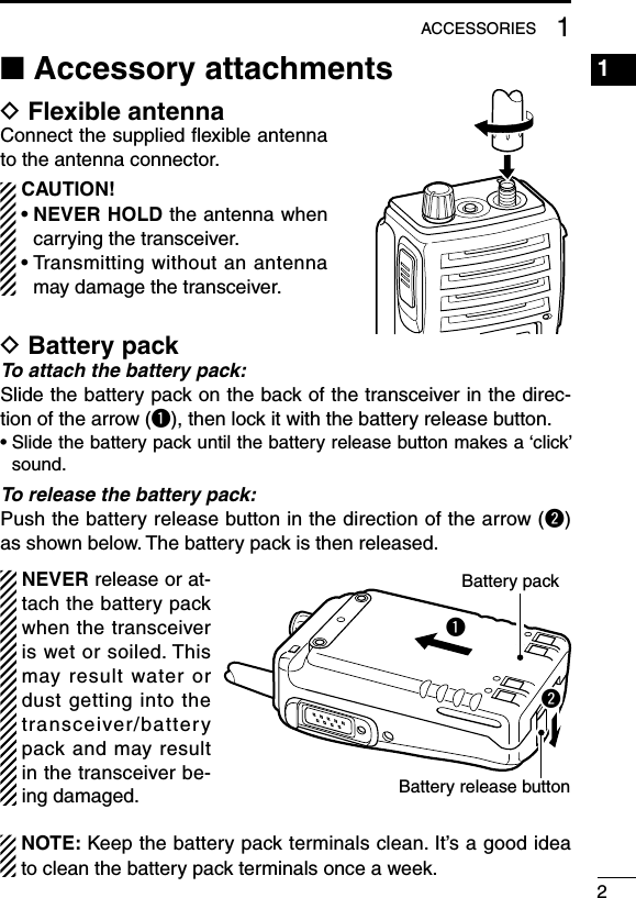
![346SPEAKER-MICROPHONE1234567891011121314151617181920■ AttachmentAttach the connector of the speaker-microphone into the [SP MIC] jack on the transceiver and tighten the screw.CAUTION: Attach the [SP MIC] jack snugly, but do not overtighten.A loose connection will allow water intrusion into the jack; an overtightened jack will damage the con-nector pins in the trans-ceiver. IMPORTANT: KEEP the [SP MIC] jack cover attached to the transceiver when the speaker-microphone is not in use. (p. 3) Water will not get into the transceiver even if the cover is not at-tached, however, the terminals (pins) will become rusty, or the transceiver will function abnormally if the connector becomes wet.](https://usermanual.wiki/ICOM-orporated/312002/User-Guide-926366-Page-41.png)
![408OPTIONS1234567891011121314151617181920VOX gain and delay adjustmentq Attach the connector of the VS-1SC into the [SP/MIC] connec-tor on the transceiver and tighten the screw. • Toggle the toggle switch to [VOX].w Enter user set mode. (pgs. 12, 19)e Push [P0] several times to select “VOX Gain” or “VOX Delay.” Then, push [ ] or [ ] to set the desired level/condition.r Rotate [VOL] to turn the power OFF to exit set mode.• VOX GainThe VOX sensitivity level can be adjusted from OFF, or 1 through 6 for greater sensitivity.VOX gain level is 3 (default)• VOX DelayThe VOX delay time can be set from 0.5 to 3.0 sec. (in 0.5 sec. steps) to set the interval before returning to receive.VOX delay timer is 0.5 sec. (default) NOTE: MIC/VOX gain can be adjusted by the adjusting pot using a thin screw driver.](https://usermanual.wiki/ICOM-orporated/312002/User-Guide-926366-Page-47.png)