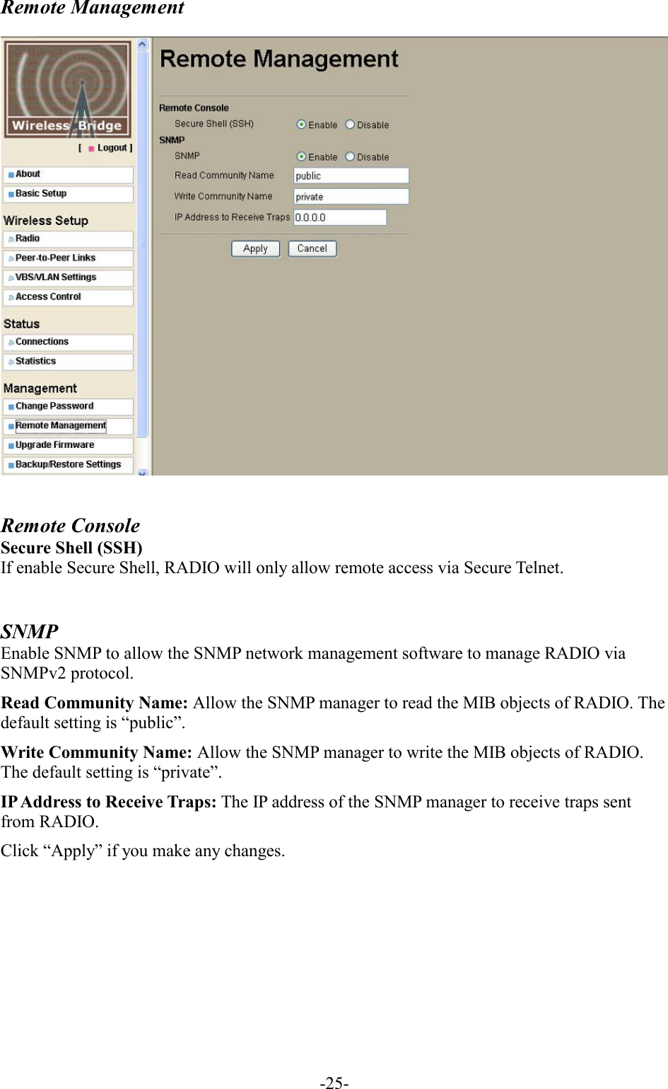
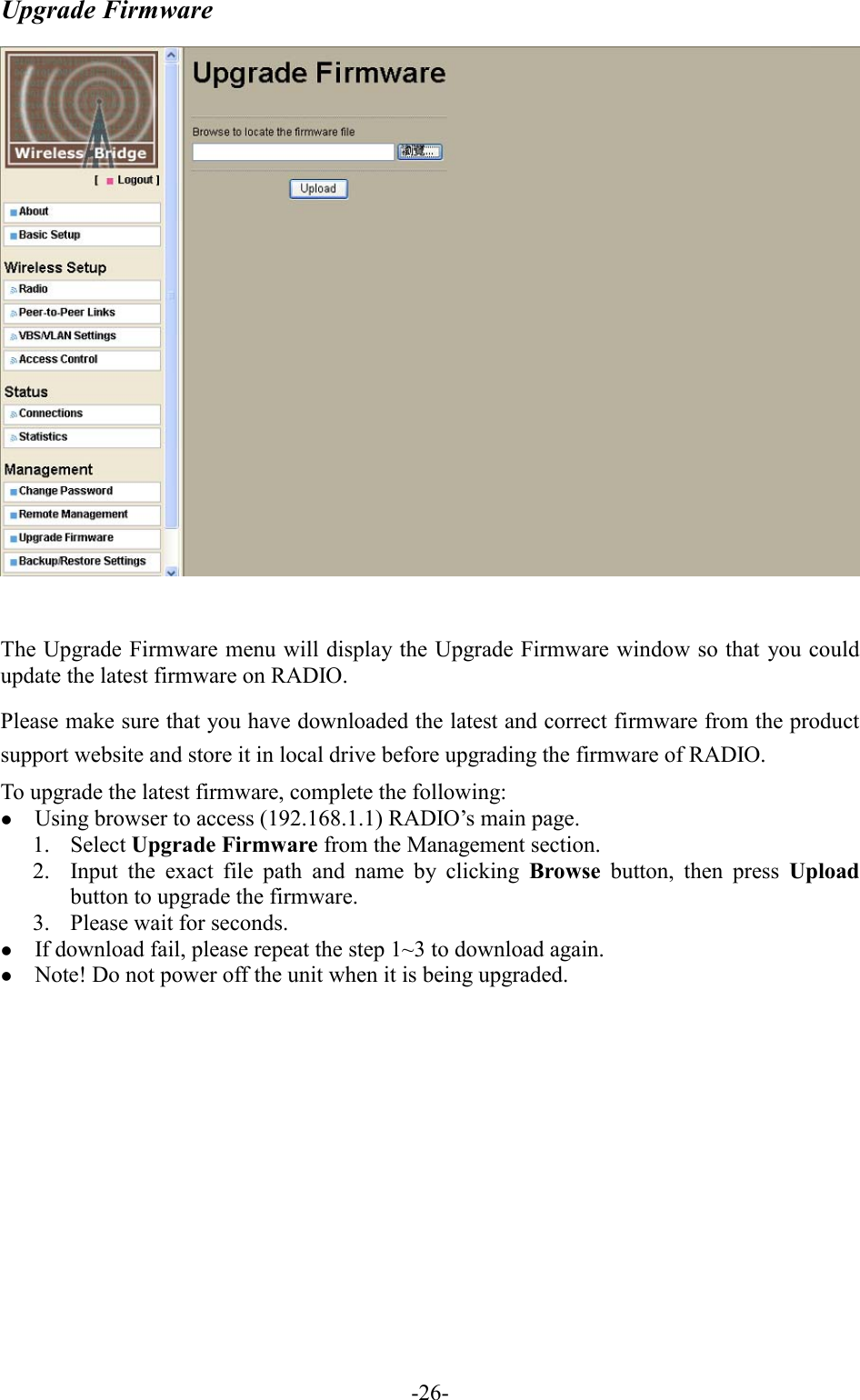
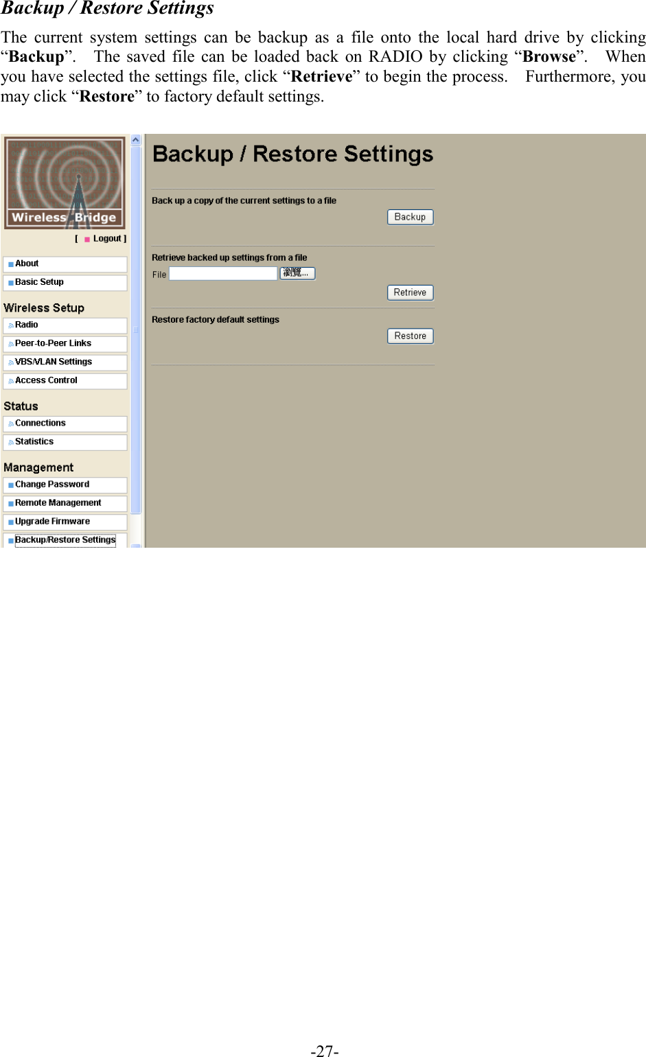
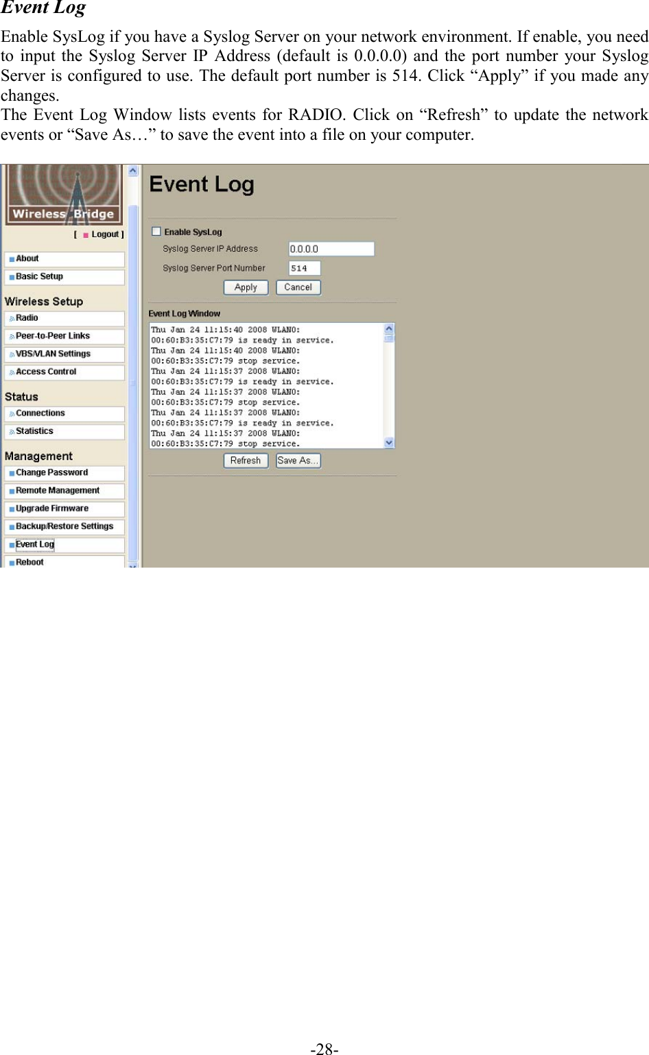
ICOM orporated 316101 Wireless Ethernet Bridge User Manual

ICOM Incorporated Wireless Ethernet Bridge

User manual

5.15~5.25GHz WLAN Radio                  ICRS-MMDS-I
 Copyright Copyright © 2005 all rights reserved. No part of this publication may be reproduced, adapted, stored in a retrieval system, translated into any language, or transmitted in any form or by any means without the written permission of the supplier.   About This Manual The purpose of this manual is for the setup of the Radio.    This manual, version 2.0.0.1 in 2008, includes procedures assisting you in avoiding unforeseen problems.      Technical Support If you have difficulty resolving the problem while installing or using the Radio, please contact the supplier for support.
FCC Notice  According to FCC 15.407(e), the device is intended to operate in the frequency band of 5.15GHz to 5.25GHz under all conditions of normal operation. Normal operation of this device is restricted to indoor used only to reduce any potential for harmful interference to co-channel MSS operations.  Reminder: To comply with FCC part 15 rules, this WLAN Radio must only be used as a system as FCC certified. The system must also be professionally installed to ensure compliance with the Part 15 certification and end users are not allowed to install by themselves. It is the responsibility of the operator and professional installer to ensure that only certified systems are deployed in where FCC rules apply.    Notice :   The changes or modifications not expressly approved by the party responsible for compliance could void the user’s authority to operate the equipment.  IMPORTANT NOTE:   1. To comply with the FCC RF exposure compliance requirements, no change to the antenna or the device is permitted. Any change to the antenna or the device could result in the device exceeding the RF exposure requirements and void user’s authority to operate the device. 2. The Radio and Antenna must be professionally installed.   FCC RF Radiation Exposure Statement: 1.  This Transmitter must not be co-located or operating in conjunction with any other antenna or transmitter. 2.  This equipment complies with FCC RF radiation exposure limits set forth for an uncontrolled environment. This equipment should be installed and operated with a minimum distance of 20 centimeters between the radiator and your body.
Table of Contents  Chapter 1 Applications ......................................................................5 Chapter 2 Hardware Installation......................................................6 2-1 Product Kit ................................................................................................... 6 2-2 System Requirements.................................................................................... 6 2-3 Mechanical Description ............................................................................... 7 2-4 Hardware Installation .................................................................................. 8 Chapter 3 Configuring the RADIO with the Web-Based User Interface .................................................................................................9 3-1 Start-up and Log in ...................................................................................... 9 3-2 Wireless Setup ............................................................................................ 12 3-3 Status .......................................................................................................... 22 3-4 Management ............................................................................................... 24 Appendix A: Troubleshooting .......................................................30 Appendix B: Authorized Cables with Cable Loss....................31 Appendix C: Specifications of Antenna......................................32
 -5-Chapter 1 Applications     1.  Remote Access to Corporate Network Information E-mail, file transfer and terminal emulation.  2. Difficult-to-Wire Environments Historical or old buildings, asbestos installations, and open area where wiring is difficult to deploy.  3.  Frequently Changing Environments Retailers, manufacturers and those who frequently rearrange the workplace and change location.  4.  Access to Database for Mobile Workers Doctors, nurses, retailers, accessing their database while being mobile in the hospital, retail store or office campus.  5.   High Security Connection The secure wireless network can be installed quickly and provide flexibility.
 -6- Chapter 2 Hardware Installation This chapter describes initial setup of the RADIO subsystem. 2-1 Product Kit Before installation, make sure that you the following items:   RADIO………....................…..……………………………………………....……..x 1   Power over Ethernet…………………………………………...….…………….…x 1   Power Adapter……………………………….…….……………………………..…x 1   Power Cord………………………………………………………………………..…x 1   Mounting kit..……………………………….…………………………………….....x 1   SFTP Cable……….….........…………….………………………..………...……....x 1   Product CD………………………………………………………………………..…x 1   Quick Installation Guide……………………………….………………………….x 1  NOTE: If any of the above items are missing or damaged, please contact your local dealer for support. 2-2 System Requirements Installation of the RADIO requires:  1.  A DC adapter which supplies the power for the PoE (Power over Ethernet). 2.  A 10/100 Base-T (UTP) Ethernet cable drop. 3.  Operating system support: Windows 98/Me/NT4.0(SP4 or above)/2000/XP
 -7-2-3 Mechanical Description RADIO:           Waterproof RJ-45 connector Connect to the POE with SFTP cable.  LED Indicator: Power / TX / RX  Reset: Remove the screw and press the reset button and keep pressing it for around 5 seconds. The RADIO will be restored to factory default settings. Then reinstall the screw with o-ring and tighten it. After Reset the RADIO, it will be restored to factory default settings. If you apply any personal configuration settings, you will need to make the changes again. N-type connector Connect to the antenna by the RF cable. The maximum RF cable length depends on the loss of the RF cable.    SFTP Cable This cable is attached to the RADIO.   RJ-45 connector (To POE)LED Indicator  Reset Button  N-type connector
 -8-2-4 Hardware Installation Take the following steps to set up your RADIO.  Connect the Ethernet Cable The Wireless LAN RADIO supports 10/100M Ethernet connection.    Connect the CAT5 cable from the RADIO to the RJ-45 connector of PoE (marked “To RADIO”) for RADIO connection. Then connect the other end of the POE with straight RJ-45 cable to a hub or a switch. Please note that, use the cross-over cable when you desire to connect the PoE of RADIO to a PC.  Connect the Antenna In RADIO connection, you can connect antenna to the N-type connector of RADIO.     Connect the Power Cable Connect adapter to the PoE, and plug the other end of the adapter into an electrical outlet.     NOTE: Only use the power adapter supplied with the PoE of RADIO. Otherwise, the product may be damaged.
 -9-Chapter 3 Configuring the RADIO with the Web-Based User Interface  3-1 Start-up and Log in  In order to configure RADIO, you must use your web browser and please do the following: 1.  Type this RADIO’s address http://192.168.1.1 in the Location (for IE) or Address field and press Enter. 2.  Enter the system name (the default setting is “admin”) and password (the default setting is “password”). 3.  Click on the “Login now” button. 4.  The main page will appear.   After you have logged-in the main page, the About, Basic Setup, Wireless Setup, Status, Management buttons will be shown. The main menu provides links to the whole sections of the web configuration interface.
 -10-About The About screen describes the product information briefly. The RADIO information includes Wireless Bridge Name, MAC Address, and Firmware Version.    Basic Setup
 -11-The Wireless Bridge Name is used to give a name to your bridge. This will enable you to manage your Wireless Bridge more easily if you have multiple Wireless Bridges on your network. Ethernet Data Rate: The basic transfer rates should be set depending on the speed of your Ethernet network. Select the desired rate from the drop-down menu and choose “Automatic” to adapt 10Mbps or 100Mbps Base-T by automatic detection. Spanning Tree Protocol : This function provides optimization of network traffic for multiple wireless bridges. You may Enable or Disable the Spanning Tree Protocol used in the wireless bridge.  VLAN(802.1Q) : VLANs can enhance performance by conserving bandwidth, and improve security by limiting traffic to specific domains. You may select the Enable will link the VLAN functionality on the Base Station.    Management VLAN ID : This allows 802.1Q VLAN devices to management the WEB GUI   of the    RADIO. The default value is “0” which allows all untagging (Non VLAN) devices to access the  RADIO.   IP Address As a Bridge mode, you can assign a proper IP address to your wireless bridge manually by selecting  Manual. If you would like the wireless bridge to obtain the IP address from the DHCP server on your network automatically, select DHCP. IP Address: Type the IP address of your bridge. (Default: 192.168.1.1). IP Subnet Mask: The Bridge’s Subnet Mask must be the same as your Ethernet network. We recommended that you do NOT change the value. (Default: 255.255.255.0). Default Gateway: The Bridge will use this value for default Gateway. Primary DNS Server: The Bridge will use this value for primary Domain Name Server. Secondary DNS Server: The Bridge will use this value for secondary Domain Name Server. Time While you connect the Bridge to Internet, the Bridge could automatically synchronize the current time of the bridge with the Time Server that you have set. Time Server: the central time of the Time Server. Time Server Port: the port of the Time Server. Time Zone: You may select the appropriate local time zone for your Bridge from a list of all available time zones. Default: GMT. Note: If you complete the settings, please click on “Apply” for changes to take effect.
 -12-3-2 Wireless Setup Radio Settings:     Operating Mode: There are three different wireless modes to operate, Base Station, CPE, and Peer-to-Peer. The default is “Base Station”. Basically, the Multi-Client mode and LAN-to-LAN mode all are used to support multiple devices to access internet through CPEs. But Multi-Client mode only supports IP packet, and LAN-to-LAN supports any Ethernet protocol. If the Base Station supports LAN-to-LAN capability(this firmware embedded), then the CPEs which connect to that Base Station could be configured to Multi-Client mode or LAN-to-LAN mode. If the Base Station doesn't support LAN-to-LAN capability(old firmware embedded), then the CPEs which connect to that Base Station should be configured to Multi-Client mode. Base Station ID: Edit VBS/VLAN Settings. Modulation: For this model, the modulation is OFDM. Channel / Frequency: Select the appropriate channel/Frequency from the list provided to correspond with your network settings. Data Rate: The basic transfer rates should be set depending on the speed of your wireless network. To specify rate of data transmission, select the desired rate from the drop-down menu and choose “Best” to adapt the rate to the best available. Output Power: Set the transmit signal strength of RADIO. The options are full, half, quarter, eighth and min. Decrease the transmit power if necessary. The best performance for max. throughput test is preset at the “full” setting. It should be selected again after being reset.
 -13-Bandwidth: Set the transmit signal bandwidth of RADIO. The default is “20MHz”. VQoS/TDM:  Enable VQoS/TDM to allow Base Station to use the technology of Time Division Multiplexing by assigning each data stream for CPE a equal time slot per cycle. The default setting is “Disable”. Antenna: For this model, the default is “Fixed on Primary” Regatta Mode: Choose “Enable” for anti-interference, it may be make better the performance of throughput. The default setting is “Disable”.  Advanced Parameters These parameters can be changed if needed, but the default advanced setting usually work well. It is recommended that you keep all these values in factory default. CPE Download Speed: This function provides flow control with a multiple of 64kbps for CPE . The setting range is 1-1687. RTS Threshold: RTS Threshold is a mechanism implemented to prevent the “Hidden Node” problem. If you have more collisions, it is recommended to enable RTS. If you have fewer collisions, it is not necessary to enable RTS. Forcing the wireless bridge to implement the RTS/CTS handshake will significantly increase the overhead and reduce throughput. If the size of the packet transmitted is larger than the value you set, the RTS should be enabled. The setting range is 0-2346. Fragmentation Length: Fragmentation mechanism is used for improving the efficiency when there is high traffic within the wireless network. If you transmit large files in a wireless network, you can enable the Fragmentation Threshold and specify the packet size. This specifies the maximum size a data packet will be before splitting and creating a new packet. The setting range is 256-2346. For example: If you set value as 256, it means the packet will be fragmented into “256” bytes while transmitting.   Bacon Interval: This value indicates the frequency interval of the beacon.    A beacon is a packet broadcast by the Base Station to keep the network synchronized. A beacon includes the wireless network service area, the Base Station address, the Broadcast destination addresses, a time stamp, Delivery Traffic Indicator Maps, and the Traffic Indicator Message (TIM). The setting range is 4-1000. Space In Meter: This space in meter is used for extending ACK time-out destination. The setting range is 0-100000. It would be better set this parameter per the actual distance. For PTMP connection, the parameter of the Center point or Base Station would be the distance between the Center and the farthest remote site. TDM Time Slice Value: The setting range is 2-32 ms.   The minimum value is 20 ms for Channel bandwidth 5MHz, 10ms for Channel bandwidth 10MHz and 5 ms for Channel bandwidth 20MHz. SoftwareRetry: The setting range is 0-15 ms. HardwareRetry: The setting range is 1-15 ms.
 -14-Site Survey   This Site Survey shows only when RADIO is CPE mode. By clicking the “Refresh” button, the Site Survey will reload and display available Base Stations around the working environment. It will display the information of each Base Station which are index, Base Station ID, MAC address, RSSI, Channel, Connect status and Encryption. To connect one of displayed Base Stations, just select the Base Station you desire and then click the “Select” button to make the connection. Click the “Back” button if you want to return to the “Radio Setting”.   Peer-to-Peer Links
 -15-The feature lets you extend the range of your network without having to use cables to link your RADIO, meaning that you can link bridge wirelessly. There are two modes in which RADIO can be configured. Select the desired mode for your environment.  VBS / VLAN Settings This section will test the VLAN functionality on the Base Station. It is expected that CPEs in the same VLAN and the same BSS can communicate with each other while CPEs in the different VLANs or in the same VLAN but the different BSSs can’t. It is also expected that Base Station can only be managed through the management VLAN.  Security Profiles:  For Base Station, there are up to 8 profiles to configure and work simultaneously. For CPE mode, you need select the CPE_Profile for encryption settings. For Peer-to-peer mode, you need select the PTP_Profile for encryption settings.  VLAN(802.1Q) Setup: Setup VLAN ID for the specified profile. Packets that are tagged (are carrying the 802.1Q VLAN ID information) can be transmitted from one 802.1Q compliant network device to another.
 -16-  Example 1 :    1. Enable Base Station VLAN function, set the BSS1 SSID as SSID1 and VLAN ID as 1,     BSS2 SSID as SSID2 and VLAN ID as 2;     2. CPE1 and CPE2 associates with SSID1, CPE3 and CPE4 associates SSID2;     3. Verify CPE1 and CPE2 can communicate with each other; CPE3 and CPE4 can communicate with each other;     4. Verify CPE1 and CPE2 can NOT communicate with CPE3 or CPE4     5. Configure the other 6 BSS to different SSID and different VLAN ID, and verify the CPEs associate with the same SSID can communicate with each other, and the CPEs associate with the different SSID can NOT communicate with each other;     6. Change every SSID to different encryption mode, repeat step2-5 to verify Base Station can still work fine.    Example 2 :
 -17-  1. Enable Base Station VLAN function and connect Base Station to Switch.     2. ETH1 and ETH2 connect to Switch and configure Switch as the following:    1) Configure the ports connecting to ETH1 and Base Station as VLAN1    2) Configure the ports connecting to ETH2 and Base Station as VLAN2    3) Configure the port type to Tagged which connect to Base Station    4) Configure the ports type to UnTagged which connect to ETH1 and ETH2     3. Set the BSS1 SSID as SSID1 and VLAN ID as 1, BSS2 SSID as SSID2 and VLAN ID as 2;     4. CPE1 associates with SSID1 and CPE2 associates with SSID2;     5. Verify CPE1 can communicate with ETH1; Verify CPE2 can communicate with ETH2;     6. Verify CPE1 can NOT communicate with ETH2, and CPE2 can NOT communicate with ETH1.           Example 3 :      1. Enable Base Station and Base Station 2 VLAN function and connect them to Switch.     2. ETH1 and ETH2 connect to Switch and configure Switch as the following:
 -18- 1) Configure the ports connecting to ETH1, Base Station 1, Base Station 2 as VLAN1    2) Configure the ports connecting to ETH2, Base Station 1, Base Station 2 as VLAN2    3) Configure the port type to Tagged which connect to Base Station 1 and Base Station 2    4) Configure the port type to Untagged which connect to ETH1 and ETH2     3. Set the BSS1 SSID as Base Station 1-SSID1 and VLAN ID as 1, BSS2 SSID as Base Station 1-SSID2 and VLAN ID as 2;     4. CPE1 associate with Base Station 1-SSID1 and CPE2 associate with Base Station 1-SSID2;    5. Set the BSS1 SSID as Base Station 2-SSID1 and VLAN ID as 1, BSS2 SSID as Base Station 2-SSID2 and VLAN ID as 2;     6. CPE3 associate with Base Station 2-SSID1 and CPE4 associate with Base Station 2-SSID2;    7. Verify CPE1,CPE3 and ETH1 can communicate with each other; Verify CPE2,CPE4       and ETH2 can communicate with each other;     8. Verify CPE1 can NOT communicate with CPE2, CPE4 and ETH2; Verify CPE2 can NOT communicate with CPE3 and ETH1;     9. Change the Base Station 2-SSID1 VLAN ID to 3, Base Station 2-SSID2 VLAN ID to 4;    10. Verify CPE1, CPE2, CPE3 and CPE4 all can NOT communicate with each other.    Example 4 :      1. Enable Base Station 1 and Base Station 2 VLAN function and connect them by a HUB;    2. Set the Base Station 1 VAP1 SSID as Base Station 1-SSID1 and VLAN ID as 1, Base Station 1 VAP2 as Base Station 1-SSID2 and VLAN ID as 2;     3. CPE1 associate to Base Station 1-SSID1, CPE2 associate to Base Station 1-SSID2;
 -19-  4. Set the Base Station 2 VAP1 SSID as Base Station 2-SSID1 and VLAN ID as 1, Base Station 2 VAP2 as Base Station 2-SSID2 and VLAN ID as 2;     5. CPE3 associate to Base Station 2-SSID1, CPE4 associate to Base Station 2-SSID2;     6. Verify CPE1 and CPE3 can communicate with each other; Verify CPE2 and CPE4 can communicate with each other;     7. Verify CPE1 cannot communicate with CPE2 and CPE4; Verify CPE2 cannot communicate with CPE1 and CPE3;     8. Change Base Station 2-SSID1 VLAN ID to 3 and Base Station 2-SSID2 VLAN ID to 4;    9. Verify that CPE1, CPE2, CPE3 and CPE4 all cannot communicate with each other.            Profile Definition: Security Profile Name is used give a name to your system. Wireless Network Name (SSID): The Base Station ID is a unique ID used by Base Station and CPEs to identify a wireless network. CPEs associating to any Base Station must have the same ID. The default ID is “Wireless”. To change the ID, type in the ID you like to use. It is case sensitive and must not exceed 32 characters. Broadcast Wireless Network Name (SSID): For security concern, you can choose not to broadcast your network’s ID. To turn off the broadcast of the ID, click “No” check box next to “Broadcast Base Station ID”. And your Base Station will refuse the connection requests from whose are not aware the Network ID. But certainly the Base Station can be easily connected well when you realize the Network ID. The default setting is “Yes”.
 -20- Network Authentication Choose the Network Authentication Type. Open System: Requires NO authentication, since it allows any device to join a network without performing any security check. The Authentication Type default is set to “Open System”. We recommend that you use the default setting. Shared Key: Requires that the CPE and the Base Station use the same WEP key to authenticate. This basically means that WEP must be enabled and configured on both the Base Station and the CPE with a same key. All points on your network must use the same authentication type. WPA-PSK: If selected, you must use TKIP encryption, and enter the WPA Pre-Shared Key. WPA2-PSK: If selected, you must use AES encryption, and enter the WPA Pre-Shared Key.  WPA Pre-Shared Key: When selecting the WAP-PSK or WPA2-PSK, you may enter 8-63 characters ranging from “a-z”, “A-Z”, and “0-9”. Data Encryption Select the desired option. If enabled (64 bit WEP, 128 bit WEP, 152 bit WEP), the keys must have the same encryption strength and must be the same with the keys that other wireless devices use. The TKIP option is automatically activated when “WPA-PSK” is enabled. And the AES option is automatically activated when “WPA2-PSK” is enabled.  64 bits WEP : Enter 10 hexadecimal digits (between 0-9, a-f and A-F). 128 bits WEP: Enter 26 hexadecimal digits (between 0-9, a-f and A-F). 152 bits WEP: Enter 32 hexadecimal digits (between 0-9, a-f and A-F). Note: The WEP key must be set up exactly the same on the RADIOs. If you set “0011223344” for the Base Station or Wireless Bridge, the same WEP key “0011223344” must be assigned to other CPEs or Wireless Bridges.    Note: If you complete the settings, please click on “Apply” for changes to take effect.  Wireless Client Security Separator Enable this function to let associated CPEs be able to separate from each other when security is required. The default setting is Disable. Note: If you complete the settings, please click on “Apply” for changes to take effect.
 -21- Access Control Authentication by username and password is only part of the story. Frequently you want to let people in based on something other than who they are. Something such as where they are coming from. Restricting access based on something other than the identity of the user is generally referred to as Access Control.    You can restrict access to only trusted CPEs so that unknown CPEs cannot wirelessly connect to the RADIO by turning Access Control on. By entering MAC Address of new stations, you can manually add the stations to allow them to be connected to the RADIO.
 -22-3-3 Status Connections   For Base Station mode, the connections page displays the association condition of Base Station includes CPE ID, MAC Address, IP Address, Moderation Data Rate, RSSI(dBm) and Status.  To display the CPE List, follow these steps: 1.  In the Wireless RADIO’s left page, choose the Connections option from Status. 2.  The CPE List window will display. By clicking the “Refresh” button, the Base Station Browser will reload and show the associated CPEs that are currently part of its Basic Service Set (BSS).
 -23-For CPE mode, the connections page or displays SSID, Channel, Wireless status, Modulation Data Rate and Signal level of connected Base Station.  Statistics   The Statistics screen provides various Ethernet and Wireless TX/RX packet statistics on your RADIO. Click the Refresh button to update the statistics on this screen.
 -24-3-4 Management Change Password   Here allow you to change RADIO’s password, do the following: 1.  To change the current password, choose the “Change Password” option from the “Management” section in RADIO’s left page. Key in the default password “password” in the “Current Password” field.   2.  Changing password for the wireless bridge is as easy as typing the password into the New Password field. Then, type it again into the Retype New Field to confirm. Click the “Apply” button to save the setting.  Note:  After you change password, please take note of your new password. Otherwise, you will not able to access RADIO setup. If you forget the password, you could restore the default password “password” by clicking the “Yes” check box in the “Restore Default Password” field or pressing the Reset button on the RADIO for at least 10 second– and all previous configurations will need to be input again.
 -25-Remote Management   Remote Console Secure Shell (SSH)   If enable Secure Shell, RADIO will only allow remote access via Secure Telnet.  SNMP Enable SNMP to allow the SNMP network management software to manage RADIO via SNMPv2 protocol. Read Community Name: Allow the SNMP manager to read the MIB objects of RADIO. The default setting is “public”. Write Community Name: Allow the SNMP manager to write the MIB objects of RADIO. The default setting is “private”. IP Address to Receive Traps: The IP address of the SNMP manager to receive traps sent from RADIO. Click “Apply” if you make any changes.
 -26-Upgrade Firmware   The Upgrade Firmware menu will display the Upgrade Firmware window so that you could update the latest firmware on RADIO. Please make sure that you have downloaded the latest and correct firmware from the product support website and store it in local drive before upgrading the firmware of RADIO. To upgrade the latest firmware, complete the following:   Using browser to access (192.168.1.1) RADIO’s main page. 1. Select Upgrade Firmware from the Management section. 2.  Input the exact file path and name by clicking Browse button, then press Upload button to upgrade the firmware. 3.  Please wait for seconds.   If download fail, please repeat the step 1~3 to download again.   Note! Do not power off the unit when it is being upgraded.
 -27-Backup / Restore Settings The current system settings can be backup as a file onto the local hard drive by clicking “Backup”.    The saved file can be loaded back on RADIO by clicking “Browse”.  When you have selected the settings file, click “Retrieve” to begin the process.    Furthermore, you may click “Restore” to factory default settings.
 -28-Event Log Enable SysLog if you have a Syslog Server on your network environment. If enable, you need to input the Syslog Server IP Address (default is 0.0.0.0) and the port number your Syslog Server is configured to use. The default port number is 514. Click “Apply” if you made any changes. The Event Log Window lists events for RADIO. Click on “Refresh” to update the network events or “Save As…” to save the event into a file on your computer.
 -29-Reboot   The Reboot screen enables you to reboot your RADIO. If any changes are made and you want them to take effect, you need to reboot RADIO. Select the “Ye s ” check box and click “Apply”. It will take you about 50 seconds to go through reboot. The Web-browser will not be accessible until RADIO has finished its reboot process.
 -30-  Appendix A: Troubleshooting If there is no signal output, please check the following item: 1. Check whether the LED indicator on the PoE and RADIO is on. If not, it means there is problem with the power component.   (1) Check if the power cord is correctly connected with the power adapter and the power outlet. (2) Check if there is electricity on power outlet.   2. Check if the connection between antenna and RADIO is correct, or whether the connector is loose or not. 3. Check if the connection between RADIO and PoE is correct, or whether the connector is loose or not. 4. Verify if the transmit power which calculated before is correct. 5. If none of the above measures could solve troubleshooting, please contact the supplier for further support.
 -31- Appendix B: Authorized Cables with Cable Loss Note: This table is for reference only.  Cable Type  Cable Loss    Cable Length (Minimum) RG142  40 dB / 100 feet  1m LMR200  26.4 dB / 100 feet  1m LMR300  16.6 dB / 100 feet  1m LMR400  10.8 dB / 100 feet  1m LMR500  8.9 dB / 100 feet  1m LMR600  7.3 dB/ 100 feet  1m
 -32-  Appendix C: Specifications of Antenna  Note : The Antenna must be professionally installed.
 -33-
 -34-
 -35-
 -36-
 -37-
 -38-

Navigation menu