ICOM orporated 316800 VHF Marine Transceiver User Manual
ICOM Incorporated VHF Marine Transceiver
UserManual.wiki
>
ICOM orporated
>
316800 User Manual
User Manual
Navigation menu
Upload a User Manual
Namespaces
Wiki Guide
HTML
PDF
Info
Views
User Manual
Discussion / Help
Navigation
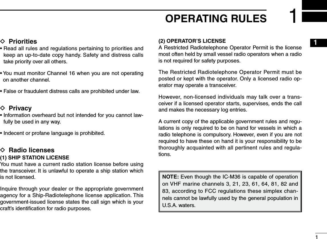
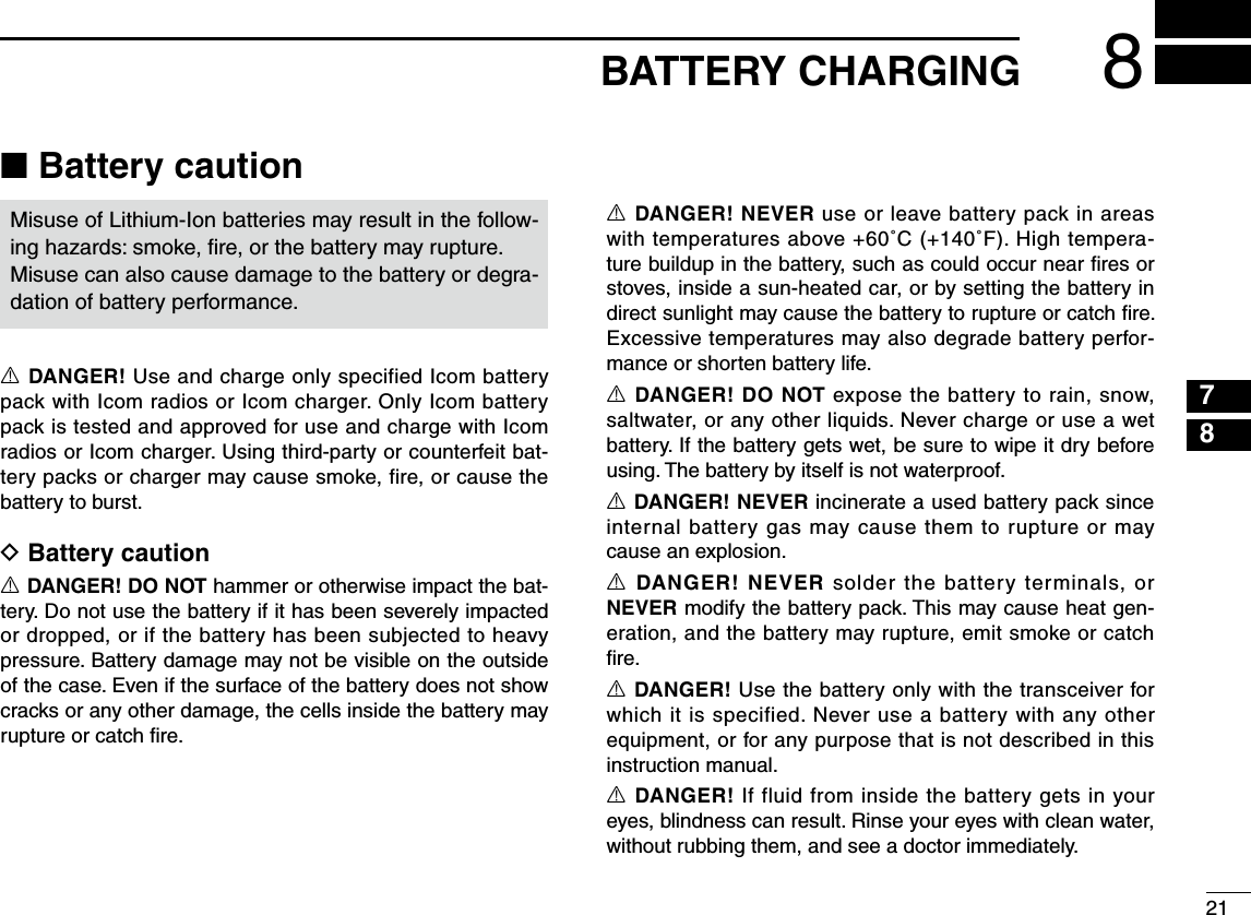
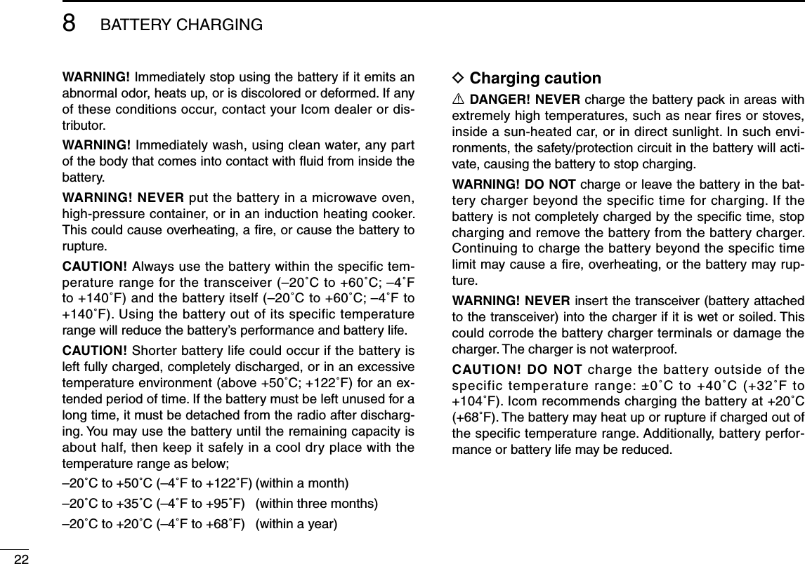
![ivRWARNING! NEVER connect the transceiver to an AC outlet. This may pose a fire hazard or result in an electric shock.RWARNING! NEVER hold the transceiver so that the antenna is closer than 2.5 cm (1 inch) from exposed parts of the body, especially the face or eyes, while transmit-ting. The transceiver will perform best if the microphone is 5 to 10 cm (2 to 4 inches) away from the lips and the trans-ceiver is vertical.NEVER connect the transceiver to a power source other than the BP-251 (option) or BP-252. Such a connection will ruin the transceiver.DO NOT use or place the transceiver in direct sunlight or in areas with temperatures below –20°C (–4°F) or above +60°C (+140°F).KEEP the transceiver out of the reach of children.KEEP the transceiver at least 0.9 meters (3.0 ft) away from your vessel’s magnetic navigation compass.BE CAREFUL! The transceiver’s right-side panel will become hot when operating continuously for long periods.BE CAREFUL! The transceiver meets IPX7* require-ments for waterproof protection. However, once the trans-ceiver has been dropped, waterproof protection cannot be guaranteed because of possible damage to the transceiver's case or the waterproof seal.* Only when the BP-251 (option) or BP-252, flexible antenna, [SP MIC] cap is attached.MAKE SURE the flexible antenna and battery pack are securely attached to the transceiver, and that the antenna and battery pack are dry before attachment. Exposing the inside of the transceiver to water will result in serious dam-age to the transceiver.After exposure to water, clean the battery contacts thor-oughly with fresh water and dry them completely to remove any water or salt residue.For U.S.A. onlyCAUTION: Changes or modifications to this device, not expressly approved by Icom Inc., could void your authority to operate this device under FCC regulations. Icom, Icom Inc. and the logo are registered trademarks of Icom Incor-porated (Japan) in the United States, the United Kingdom, Germany, France, Spain, Russia and/or other countries.PRECAUTIONS](https://usermanual.wiki/ICOM-orporated/316800/User-Guide-1029019-Page-5.png)
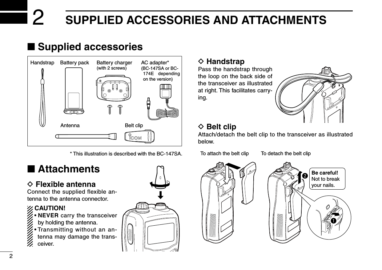
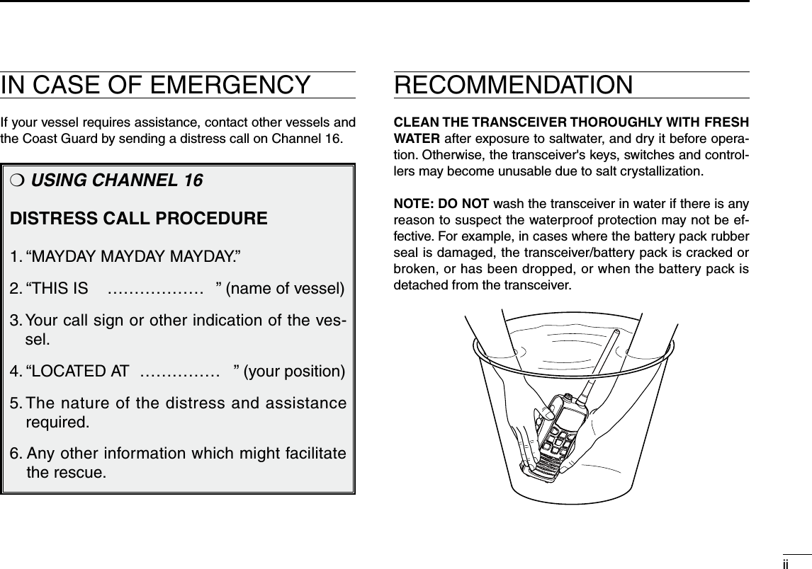
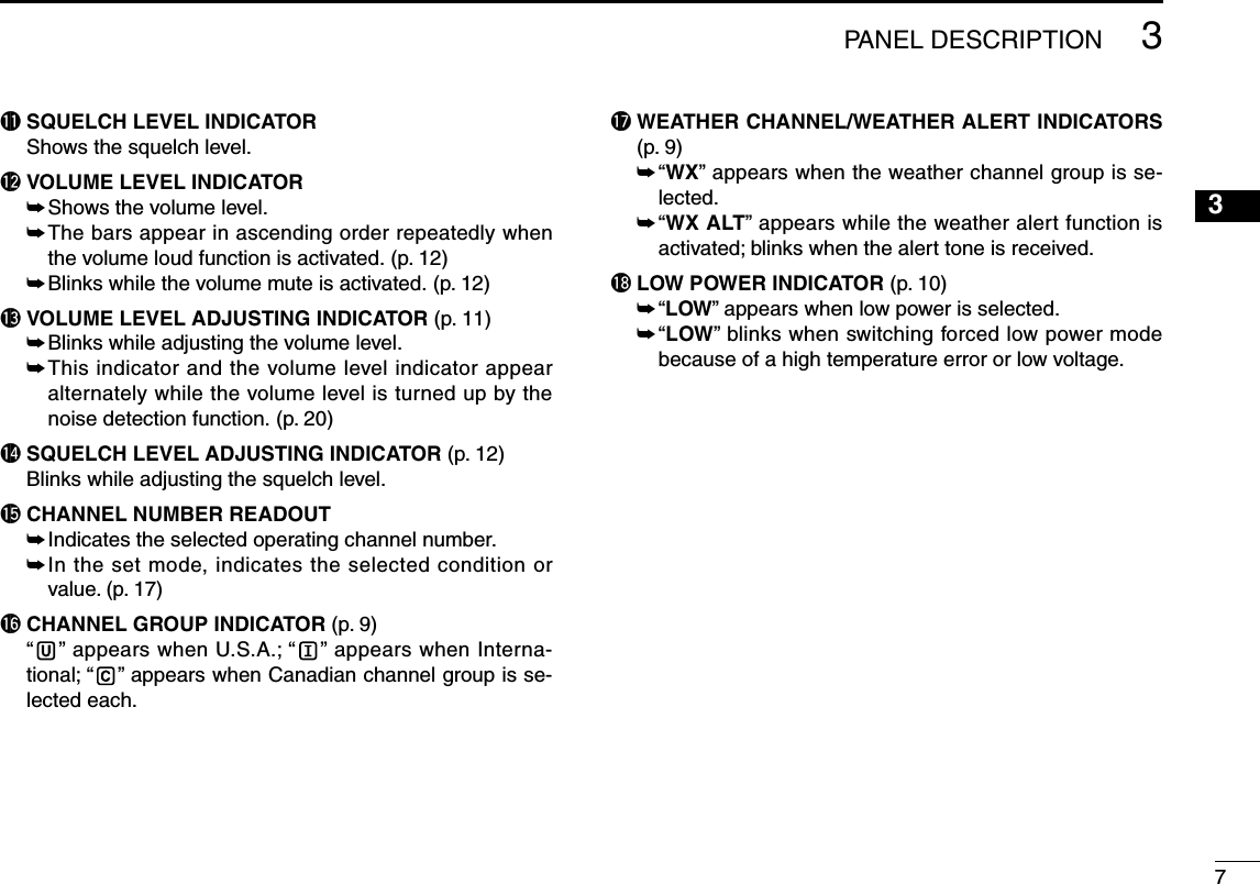
![4PANEL DESCRIPTION3■ Front, top, side and rear panelsq ANTENNA CONNECTOR (p. 2) Connects the supplied antenna.w SPEAKER-MICROPHONE CONNECTOR [SP MIC] (p. 25) Connects the optional external speaker-microphone. NOTE: Attach the [SP MIC] cap when the optional speaker-microphone is not used. Otherwise, water will get into the transceiver.q Attach the [SP MIC] cap.w Then rotate it clockwise completely.qwe PTT SWITCH [PTT] Push and hold to transmit; release to receive. (p. 10)r CHANNEL 16 KEY [16 9] ➥ Push to select Channel 16. (p. 8) ➥ Push and hold for 1 sec. to select the call channel. (p. 8) ➥ When the call channel is selected, push and hold for 3 sec. to enter the call channel programming mode. (p. 11) ➥ While in the set mode, push to return to the normal condition. (p. 17) Functiondisplay (pgs. 6, 7)Speakerytreuwq!1oi!0Microphone!2Sub-microphone(p. iii)](https://usermanual.wiki/ICOM-orporated/316800/User-Guide-1029019-Page-10.png)
![t VOLUME/SQUELCH/MONITOR KEY [VOL/SQL MONI] ➥ Push to enter the volume adjustment mode and the squelch adjustment mode. (pgs. 11, 12) ➥ Push to restore the changed volume level by the noise detection, volume loud, or volume mute function to the original. (pgs. 12, 20) ➥ Push and hold for 1 sec. to activate the monitor func-tion. (p. 13) ➥ While pushing and holding this key, turn power ON to enter the set mode. (p. 17) ➥ While in the set mode, push to select an item. (p. 17)y SCAN/DUAL KEY [SCAN DUAL] ➥ Push to start or stop normal or priority scan. (p. 15) ➥ Push and hold for 1 sec. to enter the watch mode. (p. 16) ➥ Push to exit the watch mode. (p. 16) ➥ Push and hold this key and [Hi/Lo ], to activate the AquaQuake function. (p. 13)u CHANNEL UP/DOWN KEYS [Y]/[Z] ➥ Selects an operating channel. (pgs. 8, 9) ➥ While in the set mode, selects the setting or value of an item. (p. 17) ➥ Checks TAG channels or changes scanning direction during scan. (p. 15)i FAVORITE/TAG KEY [FAV TAG] ➥ Push this key to select the favorite (TAG) channels with ignoring untagged channels in a channel group in sequence. (p. 8) ➥ Push and hold for 1 sec. to set or clear TAG for the displayed channel. (p. 15) ➥ While pushing and holding this key, turn power ON to clear or set all TAG channels in the selected channel group. (p. 15)o CHANNEL/WEATHER CHANNEL KEY [CH/WX U/I/C] ➥ Push to switch between the regular channel and weather channel. (p. 9) ➥ Push and hold for 1 sec. to select the channel group from U.S.A., International and Canada. (p. 9) ➥ Push to return to the previous channel before selecting Channel 16 or the call channel.!0 TRANSMIT POWER/LOCK KEY [Hi/Lo ] ➥ Push to select the output power from high and low. (p. 10) ➥ Push and hold for 1 sec. to turn the key lock function ON or OFF. (p. 13)!1 POWER KEY [ ] Push and hold to turn power ON or OFF.!2 LOUD/MUTE KEY [LOUD MUTE] ➥ Push to turn the volume loud function ON or OFF. (p. 12) ➥ Push and hold for 1 sec. to turn the volume mute func-tion ON, and push to turn the function OFF. (p. 12)53PANEL DESCRIPTION12345678910111213141516Volume adjustment modeNormal conditionSquelch adjustment modePUSHPUSHPUSH](https://usermanual.wiki/ICOM-orporated/316800/User-Guide-1029019-Page-11.png)
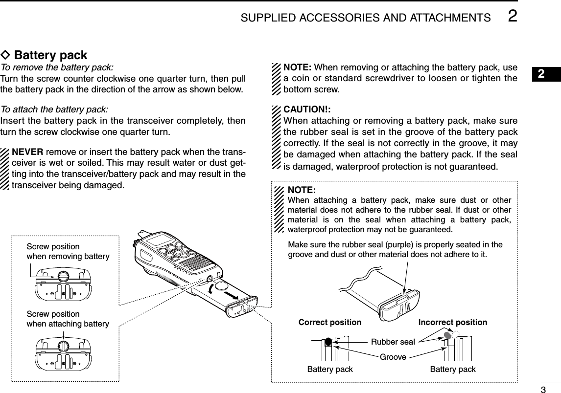
![8BASIC OPERATION4■ Channel selectionIMPORTANT!: Prior to using the transceiver for the first time, the battery pack must be fully charged for optimum life and operation. To avoid damage to the transceiver, turn the power OFF while charging.D Channel 16Channel 16 is the distress and safety channel. It used for establishing initial contact with a station and for emergency communications. Channel 16 is monitored during both Du-alwatch and Tri-watch. While in the standby condition, you must monitor Channel 16.q Push [16 9] momentarily to select Channel 16.w Push [CH/WX U/I/C] to return to the channel used before Channel 16, or push [Y]/[Z] to select a channel.Convenient!While pushing and holding [FAV TAG], push [Y]/[Z] to select the favorite (TAG) channels with ignoring untagged channels in the selected channel group in sequence.• Pushing [FAV TAG] only advances the displayed TAG channel.• The favorite channels are selected using the TAG channel setting. (p. 15)D Channel 9 (Call channel)Each regular channel group has separate leisure-use call channels. The call channel is monitored during Tri-watch. The call channels can be programmed (p. 11) and are used to store your most often used channel in each channel group for quick recall.q Push and hold [16 9] for 1 sec. to select the call channel of the selected channel group. • “CALL” and call channel number appear. • Each channel group may have an independent call channel after programming a call channel. (p. 11)w Push [CH/WX U/I/C] to return to the channel used before call channel, or push [Y]/[Z] to select a channel.PushPush and holdfor 1 sec.](https://usermanual.wiki/ICOM-orporated/316800/User-Guide-1029019-Page-14.png)
![D U.S.A., International and Canadian channelsThe transceiver is pre-programmed with 59 U.S.A., 59 Inter-national and 63 Canadian channels. These channel groups may be specified for the operating area.q Push [CH/WX U/I/C] to select a regular channel. • If a weather channel appears, push [CH/WX U/I/C] again.w Push and hold [CH/WX U/I/C] for 1 sec. to change the channel group. Repeat to advance to the next group. • U.S.A., International and Canadian channel groups can be se-lected in sequence.e Push [Y]/[Z] to select a channel. • “DUP” appears for duplex channels.Push and holdU.S.A. channelsInternational channels Canadian channels for 1 sec.D Weather channelsThe transceiver has 10 pre-programmed weather channels. These are used for monitoring broadcasts from the NOAA (National Oceanic and Atmospheric Administration).The transceiver can automatically detect a weather alert tone on the selected weather channel while receiving an-other channel or during scan. (p. 18)q Push [CH/WX U/I/C] once or twice to select a weather channel. • “WX” appears when a weather channel is selected. • “WX ALT” appears when the weather alert function is turned ON. (p. 18)w Push [Y]/[Z] to select a weather channel.94BASIC OPERATION12345678910111213141516Push once or twice.Weather alert is OFF. Weather alert is ON.](https://usermanual.wiki/ICOM-orporated/316800/User-Guide-1029019-Page-15.png)
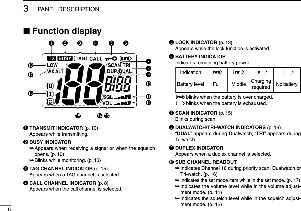
![104BASIC OPERATION■ Receiving and transmittingCAUTION: Transmitting without an antenna may damage the transceiver.q Push and hold [ ] to turn power ON.w Set the volume and squelch levels. You can enter each adjust mode with [VOL/SQL MONI]. ➥ Enter the squelch adjustment mode, and push [Z] sev-eral times to open the squelch. ➥ Enter the volume adjustment mode, then push [Y]/[Z] to adjust the volume level. ➥ Enter the squelch adjustment mode again, and push [Y] until the noise disappears.e Push [Y]/[Z] to select the desired channel. • When receiving a signal, “ ” appears and audio is emitted from the speaker. • Further adjustment of the audio may be necessary at this point.r Push [Hi/Lo ] to select the output power if necessary. • “LOW” appears when low power is selected; no indication when high power is selected. • Choose low power for short range communications, choose high power for longer distance communications. • Some channels are for low power only.t Push and hold [PTT] to transmit, then speak into the microphone. • “ ” appears. • Channel 70 cannot be used for transmission.y Release [PTT] to receive.IMPORTANT: To maximize the readability of your trans-mitted signal, pause a few sec. after pushing [PTT], hold the microphone 5 to 10 cm (2 to 4 inches) from your mouth and speak into the microphone at a normal voice level.NOTE: The transceiver has a power save function to con-serve the battery power. The power save function acti-vates automatically when no signal is received for 5 sec.For U.S.A version: To prevent accidental prolonged transmission, etc., the transceiver has a time-out timer function. This timer cuts a transmission OFF after 5 min. of continuous transmission.Microphoner Set output power.q Power ON.t Push to transmit.y Release to receive.eSet channel.Enter the volume and squelch ad-justment mode.ww Adjust the volume and squelch level.](https://usermanual.wiki/ICOM-orporated/316800/User-Guide-1029019-Page-16.png)
![■ Call channel programmingCall channel is used to access Channel 9 (default), however, you can program the call channel with your most often-used channels in each channel group for quick recall.q Push and hold [CH/WX U/I/C] for 1 sec. several times to select the desired channel group (U.S.A., International or Canada) to be programmed. (p. 9)w Push and hold [16 9] for 1 sec. to select the call channel of the selected channel group. • “CALL” and call channel number appear.e Push and hold [16 9] again for 3 sec. (until a long beep changes to 2 short beeps) to enter the call channel programming mode. • Channel number starts blinking.r Push [Y]/[Z] to select the desired channel.t Push [16 9] to program the dis-played channel as the call chan-nel. • The channel number stops blinking.■ Adjusting the volume levelThe volume level can be adjusted with [VOL/SQL MONI] and [Y]/[Z].q Push [VOL/SQL MONI] once to enter the volume adjust-ment mode, then adjust the volume level with [Y]/[Z]. • “VOL” indicator starts blinking. • The transceiver has 31 volume levels and OFF. • With no key operation is performed for 5 sec., the transceiver returns to the normal condition.w Push [VOL/SQL MONI] twice to exit the volume adjust-ment mode.114BASIC OPERATION12345678910111213141516Indicates the volume level.Blinks while adjusting the volume level.](https://usermanual.wiki/ICOM-orporated/316800/User-Guide-1029019-Page-17.png)
![124BASIC OPERATION■ Volume loud functionThe volume loud function can be activated temporarily by pushing [LOUD MUTE].The function does not work when the volume level is 31.q Push [LOUD MUTE] to activate the volume loud function. • The volume level is set to the maximum level (level 31). • The bars of the volume level indicator appears in ascending order repeatedly.w Push [LOUD MUTE] again, or push [VOL/SQL MONI] to turn the volume loud function OFF.■ Volume mute functionThe volume mute function can be activated temporarily by pushing and holding [LOUD MUTE].The function does not work when the volume level is OFF.q Push and hold [LOUD MUTE] for 1 sec. to activate the volume mute function. • The volume level is set to the minimum level (OFF). • The volume level indicator blinks.w Push [LOUD MUTE] again, or push [VOL/SQL MONI] to turn the volume mute function OFF.■ Adjusting the squelch levelThe squelch level can be adjusted with [VOL/SQL MONI] and [Y]/[Z].In order to receive signals properly, as well as for the scan to function effectively, the squelch must be adjusted to the proper level.q Push [VOL/SQL MONI] twice to enter the squelch adjust-ment mode, then adjust the squelch level with [Y]/[Z]. • “SQL” indicator starts blinking. • The transceiver has 11 squelch levels: OP is completely open; 10 is tight squelch; 1 is loose squelch. • With no key operation is performed for 5 sec., the transceiver returns to the normal condition.w Push [VOL/SQL MONI] again to exit the squelch adjust-ment mode.Indicates the squelch level.Blinks while adjusting the squelch level.](https://usermanual.wiki/ICOM-orporated/316800/User-Guide-1029019-Page-18.png)
![■ Lock functionThis function electronically locks all keys (except for [PTT], [VOL/SQL MONI], [LOUD MUTE], [Hi/Lo ] and [Y]/[Z]*) to prevent accidental channel changes and function access.* In the volume or squelch adjustment mode only.➥ Push and hold [Hi/Lo ] for 1 sec. to turn the lock func-tion ON and OFF.■ Monitor functionThe monitor function opens the squelch. The monitor key ac-tion can be selected in the set mode. (p. 19)➥ The monitor function is activated by pushing and holding [VOL/SQL MONI] for 1 sec. • “ ” blinks and the squelch is opened.■ Automatic backlightingThis function lights the function display and keys, and it is convenient for night-time operation. The automatic backlight-ing can be activated in the set mode. (p. 19)➥ Push any key except for [PTT] to turn the backlight ON. • The backlight is automatically turned OFF after 5 sec. of inactivity.■ AquaQuake water draining functionThe AquaQuake water draining function clears water away from the speaker grill. Without this function, water may muffle the sound coming from the speaker. The transceiver emits a vibrating beep when this function is activated.➥ Push and hold both [SCAN DUAL] and [Hi/Lo ]. • A low beep tone sounds for 9 sec. to drain water, regardless of the volume level setting. • The transceiver never accepts key operation while the AquaQuake function is activated. • The AquaQuake function can not be activated when an optional speaker-microphone is connected.134BASIC OPERATION12345678910111213141516Blinks while the monitor function is activated.Push and holdfor 1 sec.Appears while the lock function is activated.Push and holdfor 1 sec.](https://usermanual.wiki/ICOM-orporated/316800/User-Guide-1029019-Page-19.png)
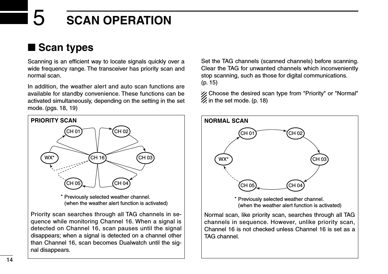
![■ Setting TAG channelsFor more efficient scanning, add the desired channels as TAG channels or clear TAG for unwanted channels.Channels that are not tagged will be skipped during scan-ning. TAG channels can be assigned to each channel group (U.S.A., International and Canada) independently.q Push and hold [CH/WX U/I/C] for 1 sec. several times to select the desired channel group.w Select the desired channel to be set as a TAG channel.e Push and hold [FAV TAG] for 1 sec. to set the displayed channel as a TAG channel. • “ ” appears on the display.r To cancel TAG channel setting, push and hold [FAV TAG] for 1 sec. • “ ” disappears.✔ Clearing (or setting) all tagged channelsWhile pushing and holding [FAV TAG], turn power ON to clear all TAG channels in the selected channel group.• Repeat above procedure to set all channels as TAG channels (when no TAG channel has been set.)■ Starting a scanSet the weather alert function, priority scan function, scan resume timer and auto scan function in advance, using the set mode. (pgs. 18, 19)q Push and hold [CH/WX U/I/C] for 1 sec. several times to select the desired channel group. • When the weather alert function is in use, select the desired weather channel with [CH/WX U/I/C] and [Y]/[Z].w Push [SCAN DUAL] to start priority or normal scan. • “SCAN” blinks in the display. • “16” appears on the sub channel readout during priority scan. • When a signal is received, scan pauses until the signal disap-pears or resumes after pausing 5 sec. according to the set mode setting. • Push [Y]/[Z] to check which channels have been set as TAG channels, change the scanning direction or resume the scan manually.e To stop the scan, push [SCAN DUAL]. • “SCAN” disappears. • Pushing [PTT], [16 9], [CH/WX U/I/C] or [FAV TAG] also stops the scan.155SCAN OPERATION12345678910111213141516[Example]: Starting a normal scan.PushBlinks BlinksScan starts When a signal is receivedAppears](https://usermanual.wiki/ICOM-orporated/316800/User-Guide-1029019-Page-21.png)
![16DUALWATCH/TRI-WATCH6■ DescriptionDualwatch monitors Channel 16 while you are receiving on another channel; Tri-watch monitors Channel 16 and the call channel while receiving another channel. Dualwatch/Tri-watch is convenient for monitoring Channel 16 when you are operating on another channel.■ Operationq Select Dualwatch or Tri-watch in the set mode. (p. 19)w Select the desired channel.e Push and hold [SCAN DUAL] for 1 sec. to start Dualwatch or Tri-watch (depending on the set mode setting). • “DUAL” blinks during Dualwatch; “TRI” blinks during Tri-watch. • A beep tone sounds when a signal is received on Channel 16. • Tri-watch becomes Dualwatch when receiving a signal on the call channel.r To cancel Dualwatch/Tri-watch, push [SCAN DUAL] again.DUALWATCH/TRI-WATCH SIMULATION• If a signal is received on Channel 16, Dualwatch/Tri-watch pauses on Channel 16 until the signal disappears.• If a signal is received on the call channel during Tri-watch, Tri-watch becomes Dualwatch until the signal dis-appears.• To transmit on the selected channel during Dualwatch/Tri-watch, push and hold [PTT].[Example]: Operating Tri-watch on INT channel 07.Tri-watch starts.Signal is received on call channel.Signal received on Channel 16 takes priority.Tri-watch resumes after the signal disappears.Dualwatch Tri-watchCallchannelCh 88Ch 16 Ch 88 Ch 16 Ch 88 Ch 9](https://usermanual.wiki/ICOM-orporated/316800/User-Guide-1029019-Page-22.png)
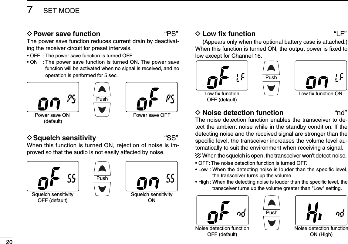
![■ Set mode programmingSet mode is used to change the conditions of transceiver's functions: Beep tone function, Weather alert function, Prior-ity scan function, Scan resume timer, Auto scan function, Dual/Tri-watch function, Monitor key action, Automatic back-lighting, LCD contrast setting, Power save function, Squelch sensitivity, Low fix function* and Noise detection function.*Appears only when the optional battery case is attached.D Set mode operationq Turn power OFF.w While pushing [VOL/SQL MONI], turn power ON to enter the set mode. • “bP” appears.e Push [VOL/SQL MONI], or push [Y]/[Z] while pushing and holding [VOL/SQL MONI] to select the desired item.r Push [Y]/[Z] to select the desired condition of the item.t To exit the set mode, push [16 9].D SET MODE ITEMS (The display shows the current settings, and the selected item is displayed in the dotted circle.)• Auto scanStarting item• Beep tone• Noise detection• Low fix*• Scan resume timer• Dual/Tri-watch• Automatic backlighting• Power save • LCD contrast • Monitor key action• Squelch sensitivity• Priority scan• Weather alert: Push + : Push or + *Appears only when the optional battery case is attached.177SET MODE12345678910111213141516](https://usermanual.wiki/ICOM-orporated/316800/User-Guide-1029019-Page-23.png)
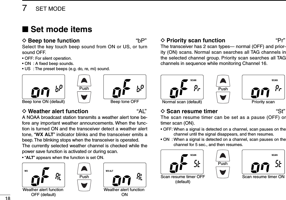
![D Auto scan function “AS”The auto scan function starts normal or priority scan auto-matically when no signal is received, and no operation is performed for 30 sec.PushAuto scan OFF (default) Auto scan OND Dual/Tri-watch function “dt”This item can be set as Dualwatch or Tri-watch. (p. 16)D Monitor key action “Sq”The monitor key opens the squelch temporarily. This item sets the key action.• Pu (PUSH) : The monitor function is activated by pushing and holding [VOL/SQL MONI] for 1 sec. The squelch opens while holding down the key.• Ho (HOLD) : The monitor function is activated by pushing and holding [VOL/SQL MONI] for 1 sec. The squelch stays open until any key is pushed.D Automatic backlighting “bL”This function is convenient for night-time operation. The backlight can be selected from ON and OFF.• The backlight is automatically activated when any key except for [PTT] is pushed.• The backlight is automatically turned OFF after 5 sec. of inactivity.D LCD contrast setting “LC”Set the LCD contrast level from High contrast and Low con-trast. The LCD contrast level makes no difference for indoor use.197SET MODE12345678910111213141516PushDualwatch function(default)Tri-watch functionPushPush setting (default) Hold settingPushHigh contrast (default) Low contrastPushAuto backlighting ON(default)Auto backlighting OFF](https://usermanual.wiki/ICOM-orporated/316800/User-Guide-1029019-Page-25.png)
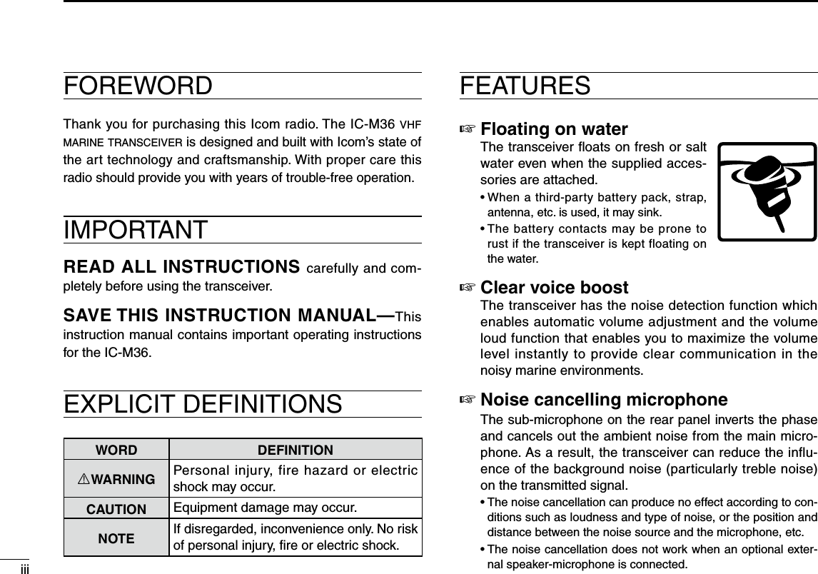
![259OPTIONAL SPEAKER-MICROPHONE12345678910111213141516■ HM-165 descriptionsPTT switchTransmits during push.Receives during release.MicrophoneSpeakerAlligator type clipTo attach the speaker-mic.to your shirt or collar, etc.Turn the transceiver power OFF when connecting the HM-165.NEVER immerse the connector in water. If the connector gets wet, be sure to dry it BEFORE attaching it to the trans-ceiver.NOTE: The microphone is located at the top of the speaker-microphone, as shown above. To maximize the readability of your transmitted signal (voice), hold the mi-crophone approx. 5 to 10 cm (2 to 4 inches) from your mouth, and speak in a normal voice level.NOTE: When the speaker-microphone is connected to the transceiver, the noise cancellation does not work.■ AttachmentTurn power OFF before attaching the speaker-microphone.Then, insert the speaker-mic connector into the [SP MIC] connector and carefully screw it tight, as shown below. Be careful not to cross-thread the connection.IMPORTANT: KEEP the transceiver’s [SP MIC] cap at-tached when the speaker-microphone is not in use. If the cover is not attached, water will get into the transceiver. Moreover, the terminals (pins) will become rusty, or the transceiver will function abnormally if the connector gets wet.CAUTION: Attach the speaker-microphone’s connector securely to prevent accidental loss, or water intrusion in the connector.Detaching:Rotate the [SP MIC] cap counter-clockwise (q), then detach it (w).Attaching:Attach the [SP MIC] cap (q), then rotate it clockwise completely (w).qwwq](https://usermanual.wiki/ICOM-orporated/316800/User-Guide-1029019-Page-31.png)
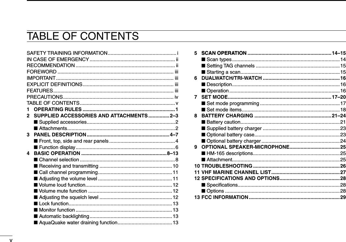
![26TROUBLESHOOTING10PROBLEM POSSIBLE CAUSE SOLUTION REF.The transceiver does not turn ON.• The battery is exhausted.• The battery pack is not attached cor-rectly.• Recharge the battery pack.• Attach the battery pack correctly.p. 23p. 3No sound from speaker. • The squelch level is too high.• Volume level is too low.• Speaker has been exposed to water.• Set the squelch level to the threshold level.• Adjust the audio level to a suitable level.• Drain water from the speaker.p. 12p. 11p. 13Transmitting is impossible, or high power can not be se-lected.• Some channels are for low power or re-ceive only.• The battery is exhausted.• The battery is over charged.• The output power is set to low.• Change channels.• Recharge the battery pack.• Make sure the battery voltage is correct.• Push [Hi/Lo ] to select high power.pgs. 8, 9, 27p. 23—p. 10The displayed channel cannot be changed.• Lock function is activated. • Push and hold [Hi/Lo ] for 1 sec. to cancel the function.p. 13Scan does not start. • “TAG” channels are not programmed. • Set the desired channels as “TAG” chan-nels.p. 15No beep emits. • Beep tone function is turned OFF. • Set the beep tone to ON (Fix Beep/User Beep) in the set mode.p. 18Battery voltage error. • The connected battery pack’s voltage is more than 11 V.• Make sure the battery voltage is correct. —The noise cancellation does not work.• The sub-microphone is covered with something.• An optional external speaker-micro-phone is connected.• Make sure the sub-microphone is not covered.• Disconnect the microphone.p. 4p. 25The noise detection function does not work.• The sub-microphone is covered with something.• The squelch is open.• Make sure the sub-microphone is not covered.• Set the squelch level to the desired level.p. 4p. 12](https://usermanual.wiki/ICOM-orporated/316800/User-Guide-1029019-Page-32.png)