ICOM orporated 333100 VHF Mobile Transceiver User Manual IC F5020 F6020 series Instruction Manual
ICOM Incorporated VHF Mobile Transceiver IC F5020 F6020 series Instruction Manual
UserManual.wiki
>
ICOM orporated
>
333100 User Manual
User Manual
Navigation menu
Upload a User Manual
Namespaces
Wiki Guide
HTML
PDF
Info
Views
User Manual
Discussion / Help
Navigation
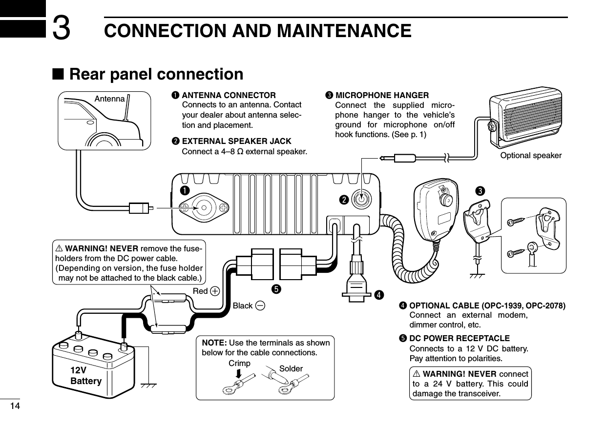
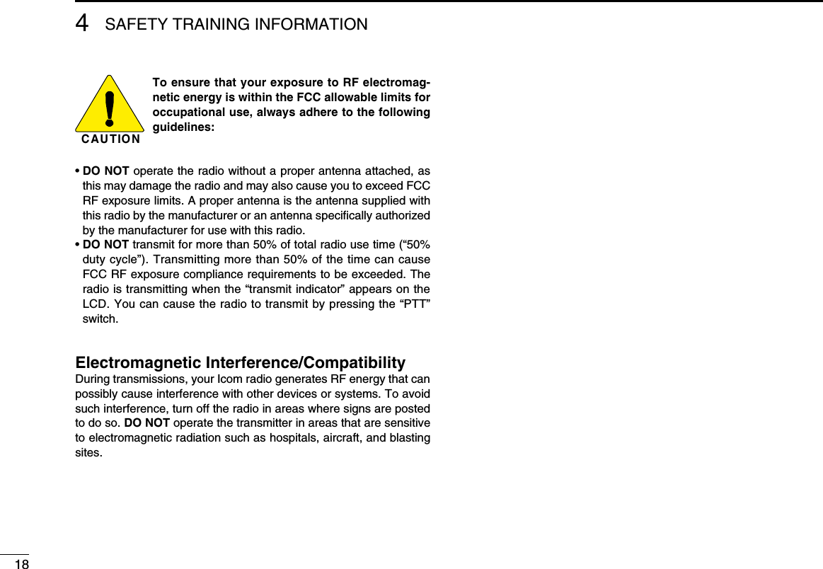
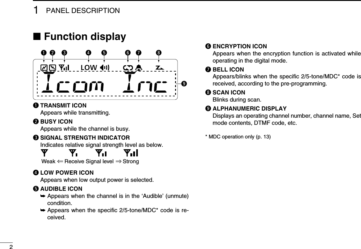
![112345678910111213141516q wtSpeakerFunction display (p. 2)re■ Front panelq AF VOLUME CONTROL KNOB [VOL] Rotate the knob to adjust the desired audio output level. • Minimum audio level is pre-set. (p. 11)w UP/DOWN KEYS [CH Up]/[CH Down] Push to select an operating channel, etc. * The desired function can be assigned by your dealer. (p. 3)e POWER KEY [ ]Push to turn the power ON and OFF. • The following functions are available at power ON as options: - Automatic scan start - Password prompt - Set moder DEALER-PROGRAMMABLE KEYS Desired functions can be programmed independently by your dealer. (p. 3)t MICROPHONE CONNECTOR Connect the supplied or optional microphone. NEVER connect non-specified microphones. The pin assignments may be different and the transceiver may be damaged.D MICROPHONEThe supplied or optional microphone has a PTT switch and a hanger hook.• The following functions are available when the microphone is on or off hook (depending on the setting): - Automatic scan starts when it is on hook. - Scan is cancelled when it is off hook. - Scan is paused when it is off hook. - Automatic priority channel selection is available when it is off hook. - Sets to ‘Inaudible’ condition (mute condition) when it is on hook. - Sets to ‘Audible’ condition (unmute condition) when it is off hook.1PANEL DESCRIPTION](https://usermanual.wiki/ICOM-orporated/333100/User-Guide-1391904-Page-5.png)
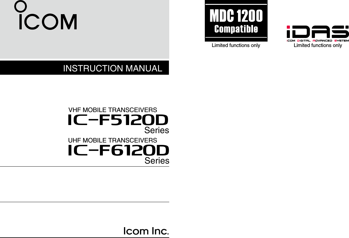
![31PANEL DESCRIPTION12345678910111213141516■ Programmable function keysThe following functions can be assigned to [UP], [DOWN], [P0], [P1], [P2] and [P3] programmable function keys.Consult your Icom dealer or system operator for details con-cerning your transceivers programming.If the programmable function names are bracketed in the fol-lowing explanations, the specific key is used to activate the function depends on the programming.CH UP AND DOWN KEYS ➥Push to select an operating channel.➥ Push to select a transmit code channel after pushing [TX Code CH Select].➥ Push to select a DTMF channel after pushing [DTMF Au-todial].➥ Push to select a scan group after holding down [Scan Start/Stop] for 1 sec.ZONE KEYPush this key, then select the desired zone using [CH Up]/ [CH Down]. What is “zone”?— Selected channels are assigned to a zone according to how they are to be used in a group. For example, ‘Staff A’ and ‘Staff B’ are assigned into a “Busi-ness” zone, and ‘John’ and ‘Cindy’ are assigned into a “Private” zone.SCAN KEY➥Push to start and cancel scanning operation. • When Power ON Scan function is activated, push to pause the scanning operation. And the paused scan restarts after the specified time period has passed.➥Hold down this key for 1 sec. to indicate the scan list, then push [CH Up] or [CH Down] to select the desired list.SCAN ADD/DEL (TAG) KEY➥ Push to add/delete the selected channel to/from the scan list. 1. Push to indicate the scan group, then push [CH Up] or [CH Down] to select the desired list. 2. Push to add or delete the channel to/from the selected scan list. 3. Hold down for 1 sec. to exit the scan list selection mode.➥ Push this key while scan is paused (a signal is detected) on a channel (except for priority channel), the channel is cleared from the scan list. Depending on the setting, the cleared channel is added to the scan list again after the scan is cancelled.](https://usermanual.wiki/ICOM-orporated/333100/User-Guide-1391904-Page-7.png)
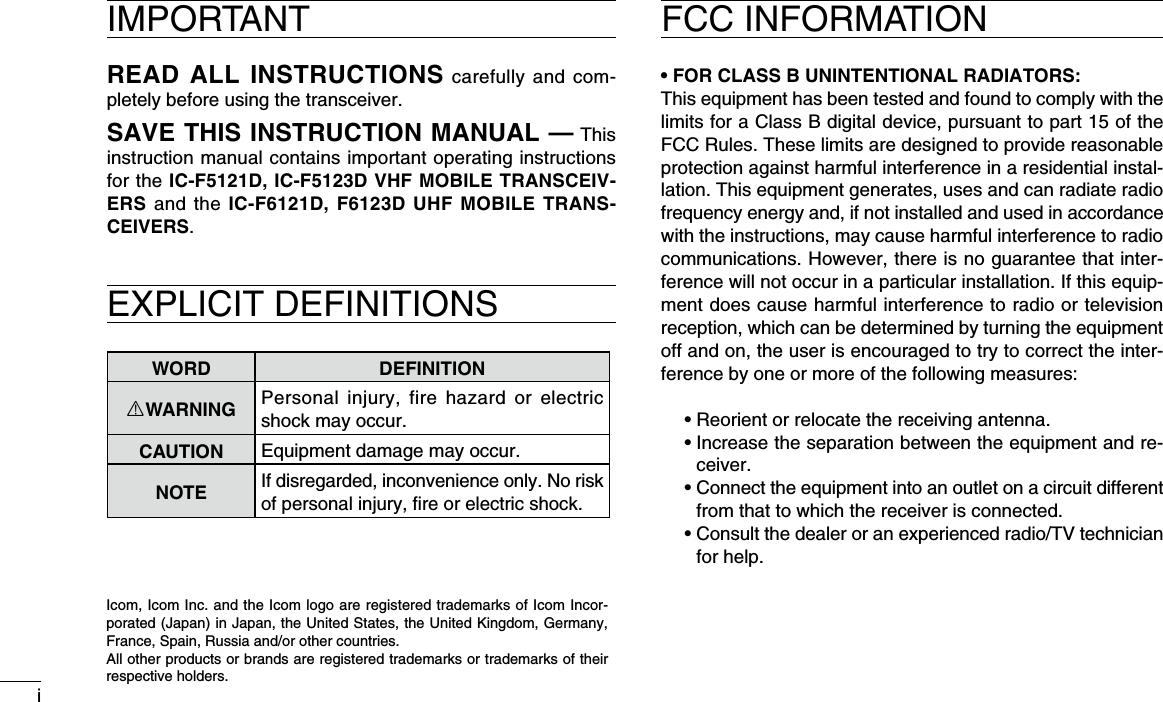
![41PANEL DESCRIPTIONPRIO A/B KEYS➥ Push to select Priority A or Priority B channel.➥ Hold down [Prio A (Rewrite)] or [Prio B (Rewrite)] for 1 sec. to rewrite the operating channel as the Priority A or Priority B channel.MR-CH 1/2/3/4 KEYSPush to select the memory channel 1 to 4 directly.MONI (AUDI) KEY ➥ Push to mute and release the CTCSS (DTCS) or 2-tone squelch mute. Open any squelch/deactivate any mute while pushing and holding this key. (LMR operation only)➥ Activates one of (or two of) the following functions on each channel independently: (PMR operation only) • Hold down to unmute the channel (audio is emitted; ‘Audible’ condition). • Push to mute the channel (sets to ‘Inaudible’ only). • Push after the communication is finished to send a ‘reset code’. (5-tone operation only) NOTE: The un-mute condition (‘Audible’ condition) may automatically return to the mute condition (‘Inaudible’ condition) after a specified period depending on pro-gramming.LOCK KEYHold down to electronically lock all programmable keys ex-cept the following:[Moni(Audi)], [Lock], [Call] (incl. Call A and Call B), [Emergency], [Surveillance], [Siren], [Lone Worker] and [Light].LONE WORKER KEYPush to turn the Lone Worker function ON or OFF.• If the Lone Worker function is activated, Emergency function is au-tomatically turned ON after the specified time period has passed with no operation is performed.HIGH/LOW KEYPush to select the transmit output power temporarily or per-manently, depending on the pre-setting.• Ask your dealer for the output power level for each selection.C.TONE CH ENT KEYPush to enter the continuous tone channel selection mode. Then, push [CH Up]/[CH Down] to change the tone fre-quency/code setting. The selected channel remains set as the continuous tone channel until another channel is desig-nated as such. TALK AROUND KEYPush to turn the talk around function ON and OFF.• The talk around function equalizes the transmit frequency to the receive frequency for transceiver-to-transceiver communication.](https://usermanual.wiki/ICOM-orporated/333100/User-Guide-1391904-Page-8.png)
![51PANEL DESCRIPTION1WIDE/NARROW KEYPush to toggle the IF bandwidth between wide and narrow. • The wide passband width can be selected from 25.0 or 20.0 kHz using the CS-F3100D/F5120D cloning software. (PMR operation only) Ask your dealer for details.DTMF AUTODIAL KEY➥ Push to enter the DTMF channel selection mode. And then select the desired DTMF channel using [CH Up]/[CH Down].➥ After selecting the DTMF channel, push again to transmit the selected DTMF code.RE-DIAL KEYPush to transmit the last-transmitted DTMF code.• TX memories are cleared after turning the transceiver OFF.CALL KEYSPush to transmit a 2/5-tone ID code.• Call transmission is necessary before calling another station de-pending on your signalling system.• [Call A] and/or [Call B] may be available when your system em-ploys selective ‘Individual/Group’ calls. Ask your dealer which call is assigned to each key.EMERGENCY KEYHold down this for specified period to transmit an emergency call.• The emergency call transmits with beeps; the display does not change.• The transceiver can transmit an emergency call with no beep emis-sion and LCD indication change depending on the pre-setting. Ask your dealer for details.• If you want to cancel the emergency call, hold down the key again before transmitting the call.• The emergency call is transmitted one time only or repeatedly until receiving a control code, depending on the pre-setting.SURVEILLANCE KEYPush to turn the surveillance function ON or OFF.When this function is turned ON, the beep is not emitted and the LCD backlight does not light when a signal is received or a key is pushed, etc.SIRENHold down for 1 sec. to sound the siren.• The siren can only be stopped by turning OFF the transceiver power.TX CODE ENTER KEY (PMR operation only)Push to enter the TX code edit mode directly.Then set the desired digit using [CH Up]/[CH Down]. (p. 10)](https://usermanual.wiki/ICOM-orporated/333100/User-Guide-1391904-Page-9.png)
![61PANEL DESCRIPTIONTX CODE CHANNEL SELECT KEY➥ Push to enter the TX code channel selection mode. Then set the desired channel using [CH Up]/[CH Down]. (p. 9)➥ While in the TX code channel selection mode, hold down this key for 1 sec. to enter the TX code edit mode. Then set the desired digit using [CH Up]/[CH Down]. (p. 10)TX CODE CHANNEL UP/DOWN KEYSPush to select a TX code channel directly.ID-MR SELECT KEY (PMR operation only)➥ Recalls detected ID codes. • Push this key, then select the ID code using [CH Up]/ [CH Down]. • Up to 5 ID’s are memorized.➥ Hold down this key for 1 sec. to erase the selected ID’s.ENCRYPTION KEY➥ Push to turn the voice encryption function ON and OFF while operating in the digital mode.USER SET MODE KEY➥ Hold down for 1 sec. to enter user set mode. • During user set mode, push this key to select an item*, and change the value or condition using [CH Up]/[CH Down]. *Selectable items may differ depending on the pre-setting.➥ Hold down this key for 1 sec. again to exit user set mode.User set mode is also available via the ‘Power ON’ function. In this case, all set mode items are available. Refer to p. 11 also.Ext. CH Sel Mode KEYPush to turn the Ext. CH Select function ON or OFF. When the function is turned ON, memory channels can be selected with external input operation only. When the function is turned OFF, memory channels can be selected with [CH Up] or [CH Down] operation, and cannot with external input operation. • This function is available when the external unit, such as a dimmer control is connected to the transceiver with an optional cable, OPC-1939 or OPC-2078 (p. 16).• Ask your dealer for details of external input operation.](https://usermanual.wiki/ICOM-orporated/333100/User-Guide-1391904-Page-10.png)
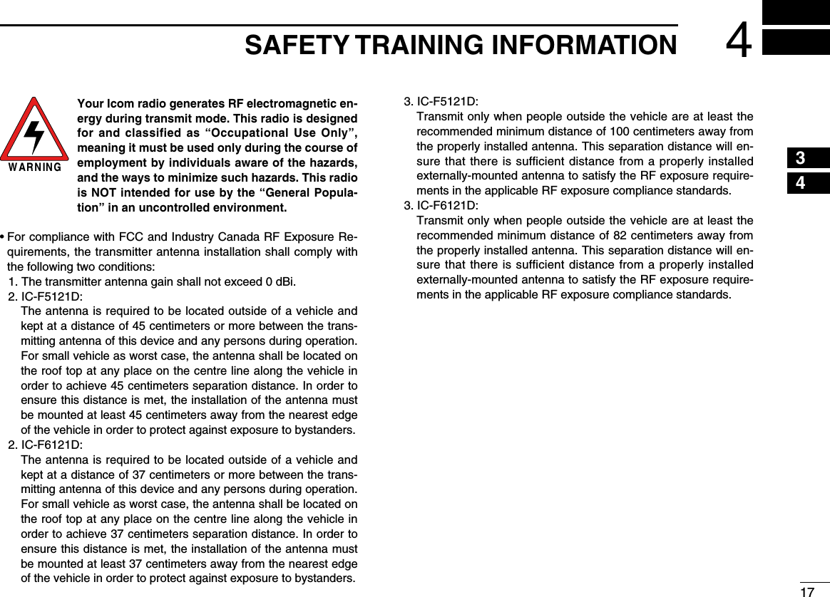
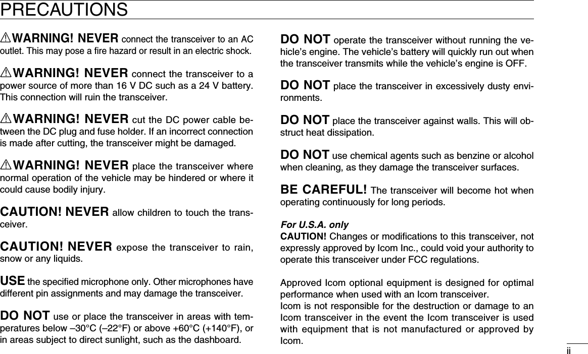
![72BASIC OPERATION12345678910111213141516■ Turning power ONq Push [ ] to turn the power ON.w If the transceiver is programmed for a start up password, input the digit codes as directed by your dealer. • The keys as below can be used for password input: The transceiver detects numbers in the same block as identical. Therefore “01234” and “56789” are the same.e When the “PASSWORD” indication does not clear after inputting 4 digits, the input code number may be incorrect. Turn the power off and start over in this case.■ Channel selectionSeveral types of channel selections are available. Methods may differ according to your system set up.NON-ZONE TYPE:Push [CH Up] or [CH Down] to select the desired operating channel, in sequence; or, push one of [MR-CH 1] to [MR-CH 4] keys to select a channel directly.ZONE TYPE:Push [Zone], then push [CH Up] or [CH Down] to select the desired zone.AUTOMATIC SCAN TYPE:Channel setting is not necessary for this type. When turn-ing power ON, the transceiver automatically starts scanning. Scanning stops when receiving a call.KEYNUMBER 0549382716](https://usermanual.wiki/ICOM-orporated/333100/User-Guide-1391904-Page-11.png)
![82BASIC OPERATION■ Call procedureWhen your system employs tone signaling (excluding CTCSS and DTCS), a call procedure may be necessary prior to voice transmission. The tone signalling employed may be a selec-tive calling system which allows you to call specific station(s) only and prevents unwanted stations from contacting you.q Select the desired TX code channel, 2/5-tone code ac-cording to your System Operator’s instructions. • This may not be necessary depending on programming. • Refer to pages 9–10 for selection.w Push [Call] (assigned to one of the dealer programmable keys).e After transmitting, the remainder of your communication can be carried out in the normal fashion.Selective calling Non-selective calling■ Receiving and transmittingReceiving:q Hold down [ ] for 1 sec. to turn the power ON.w Push [CH Up] or [CH Down] to select a channel, in se-quence.e When receiving a call, rotate [VOL] to adjust the audio output level to a comfortable listening level.NOTE: Depending on the pre-setting, the transceiver auto-matically transmits the microphone audio for the specified time period* when a matched RX code signal is received.• HM-148G or HM-152 hand microphone is required.* Depending on the pre-setting. Ask your dealer for details.Transmitting:Wait for the channel to become clear to avoid interference.q Take the microphone off hook. • The ‘audible’ condition is selected. • A priority channel may be selected automatically.w Wait for the channel to become clear. • The channel is busy when BUSY indicator appears on the LCD.e While pushing and holding [PTT], speak into the micro-phone at your normal voice level.r Release [PTT] to return to receive. IMPORTANT: To maximize the readability of your signal; 1. Pause briefly after pushing [PTT]. 2. Hold the microphone 5 to 10 cm (2 to 4 inches) from your mouth, then speak into the microphone at a normal voice level.](https://usermanual.wiki/ICOM-orporated/333100/User-Guide-1391904-Page-12.png)
![92BASIC OPERATION12345678910111213141516D Transmitting notes• Transmit inhibit function The transceiver has several inhibit functions which restrict transmission under the following conditions: - The channel is in mute condition (‘Inaudible’ condition; “ ” (Audible icon) does not appear.) - The channel is busy. - Un-matched (or matched) CTCSS is received. (Depending on the pre-setting) - The selected channel is a ‘receive only’ channel.• Time-out timer After continuous transmission for the pre-programmed time period, the time-out timer is activated, causing the trans-ceiver to stop transmitting.• Penalty timer Once the time-out timer is activated, transmission is further inhibited for a period determined by the penalty timer.• PTTID call The transceiver sends the ID code (5-tone, DTMF or digital ANI) automatically when [PTT] is pushed (beginning of the transmission) and/or released (end of transmission) depend-ing on the setting. PTTID call is also available with the MDC 1200 signal-ing system. (p. 13)D TX code channel selectionIf the transceiver has [TX Code CH Select] assigned to it, the indication can be toggled between the operating channel number (or name) and TX code channel number (or name). When the TX code channel number (or name) is displayed, [CH Up] or [CH Down] selects the TX code channel.USING [TX CODE CH SELECT] KEY:q Push [TX Code CH Select]— a TX code channel number (or name) appears.w Push [CH Up] or [CH Down] to select the desired TX code channel.e After selecting, push [TX Code CH Select] to set. • Return to the stand-by mode.r Push [Call] to transmit the selected TX code.USING [TX CODE CH UP]/[TX CODE CH DOWN] KEY:If the transceiver has a [TX Code CH Up] or [TX Code CH Down] key assignment, the programmed TX code channel can be selected directly when pushed.](https://usermanual.wiki/ICOM-orporated/333100/User-Guide-1391904-Page-13.png)
![102BASIC OPERATIOND TX code number edit (PMR operation only)If the transceiver has [TX Code CH Select] or [TX Code Enter] assigned to it, TX code contents can be edited within the allowable digits.USING [TX CODE CH SELECT] KEY:q Push [TX Code CH Select] to enter the TX code channel selection mode. • Select the desired operating channel before entering the TX code channel selection mode if necessary.w Push [TX Code CH Select] for 1 sec. to enter the TX code edit mode. • The digit to be edited blinks.e Push [TX Code CH Select] to select the desired digit to be edited.r Push [CH Up] or [CH Down] to select the desired digit.t Push [TX Code CH Select] to set. The digit to the right will blink automatically.y Repeat r and t to edit all allowable digits.u After editing, push [TX Code CH Select] to set. • Return to the stand-by mode.i Push [Call] to transmit.USING [TX CODE ENTER] KEY:q Push [TX Code Enter] to enter the TX code edit mode. • The digit to be edited blinks.w Push [TX Code Enter] to select the desired digit to be edited.e Push [CH Up] or [CH Down] to select the desired digit.r Push [TX Code Enter] to set. The digit to the right will blink automatically.t Repeat e and r to edit all allowable digits.y After editing, push [TX Code Enter] to set. • Return to the stand-by mode.u Push [Call] to transmit.D DTMF transmissionIf the transceiver has [DTMF Autodial] assigned to it, the automatic DTMF transmission function is available. Up to 8 DTMF channels are available.q Push [DTMF Autodial]— a DTMF channel appears.w Push [CH Up] or [CH Down] to select the desired DTMF channel.e Push [DTMF Autodial] to transmit the DTMF code.](https://usermanual.wiki/ICOM-orporated/333100/User-Guide-1391904-Page-14.png)
![112BASIC OPERATION2■ User set modeUser set mode can be accessed with ‘Power ON’ function. In this case, all set mode items are available. User set mode allows you to set seldom-changed settings and you can “customize” the transceiver operation to suit your preferences and operating style.Entering the user set mode:q While holding down [P1] and [P2], push [ ] to turn the power ON. • Turn power OFF in advance. • Hold down [P1] and [P2] continuously until “SET MODE” ap-pears on the display.[P1] [P2] [ ]w Hold down [P0] for 1 sec. to enter user set mode.[P0]e Push [P0] several times to select the appropriate item. Then, push [Up] or [Down] to set the desired level/condi-tion. • Available set mode functions are Backlight, Beep, Beep Level, Ringer Level, SQL Level, AF Min Level, Mic Gain, Horn, Bat-tery Voltage, Signal Moni and Lone Worker.[P0] [Up]/[Down]r Hold down [ ] for 1 sec. to turn power OFF, then ON again to exit set mode.[ ]User set mode is also available using a programmable key. Please refer to p. 6 [User Set Mode] section for instructions regarding using the key assigned for user set mode.[User Set Mode] is allowed for the quick item selection. Set “Enable” for the often used items with the CS-F3100D/F5120D cloning software.](https://usermanual.wiki/ICOM-orporated/333100/User-Guide-1391904-Page-15.png)
![122BASIC OPERATION■ Encryption functionThe encryption function provides private communication be-tween stations while operating in the digital mode.q Push [Encryption] to turn the encryption function ON. • “ ” (Encryption icon) appears.w Push [Encryption] again to turn the encryption function OFF. • “ ” disappears.■ Emergency transmissionThe emergency call can be performed using [Emergency]. (p. 5)When [Emergency] is pushed for the specified time period, the DTMF or 5-tone emergency signal is transmitted once or repeatedly on the emergency channel depending on the channel. However, when no emergency channel is specified, the signal is transmitted on the previously selected channel.If you want to cancel the emergency call, hold down the key again before transmitting the call.Emergency call is also available with the MDC 1200 signaling system. (p. 13)■ Stun functionWhen the specified ID, set as a stun ID or kill ID, is received, the stun function is activated.When the stun ID is received, the transceiver becomes unus-able. Entering of the password (p. 8) or receiving a specified ID, set as a revive ID, is necessary to operate the transceiver again in this case.When the kill ID is received, the transceiver switches to the cloning required condition. Cloning the transceiver is neces-sary to operate the transceiver again in this case.Stun function is also available with the MDC 1200 signaling system. (p. 13)■ Priority A channel selectionWhen one of the following operations is performed, the trans-ceiver selects the Priority A channel automatically. • Turning the power ON The Priority A channel is selected each time the trans-ceiver power is turned ON. • Off hook. The Priority A channel is selected when the microphone is took off from its hanger.](https://usermanual.wiki/ICOM-orporated/333100/User-Guide-1391904-Page-16.png)
![1312345678910111213141516■ MDC 1200 system operationThe MDC 1200 signaling system enhances your trans-ceiv-er’s capabilities. It allows PTT ID*, Emergency signaling, and receiving Radio Check. Also, the dispatcher can stun and re-vive transceivers on the system.An additional feature of MDC 1200 system found in Icom transceivers is called aliasing. Each transceiver on the system has a unique ID number. Aliasing allows the substitution of an alphanumeric name for this ID number. For transmit, you can use this alias to select a transceiver to call. For receive, the alias of the calling station is displayed instead of the ID.* When [PTT] is pushed and/or released, the transceiver transmits your own station ID.D Receiving an Emergency Callq When an emergency call is received; • Beeps sound. • The calling station ID (or alias) and “EMG EMG” are displayed alternately.w Turn power OFF, change the channel, push [PTT] for reply-ing the call, etc. to stop the beep and display indication.D Transmitting an Emergency Call The MDC 1200 system Emergency feature can be accessed using the [Emergency] key (p. 5). The transceiver will send an Emergency MDC 1200 system command once or repeat-edly for a programmed number of times until it receives the acknowledgement signal.The emergency call can be transmitted without a beep emis-sion, and the LCD indication change depends on how emer-gency is programmed. Ask your dealer for details.D Receiving a Stun and ReviveThe dispatcher can send MDC 1200 system signals that will stun or revive your transceiver. If a Stun command is re-ceived that matches your station ID, the transceiver will dis-play “SORRY” (default) and you can not receive or transmit. When a Revive command is received that matches your sta-tion ID, normal operation is restored.2BASIC OPERATION](https://usermanual.wiki/ICOM-orporated/333100/User-Guide-1391904-Page-17.png)