ICOM orporated 334000 VHF Marine Transceiver User Manual IC M24 2 indd
ICOM Incorporated VHF Marine Transceiver IC M24 2 indd
UserManual.wiki
>
ICOM orporated
>
334000 User Manual
User Manual
Navigation menu
Upload a User Manual
Namespaces
Wiki Guide
HTML
PDF
Info
Views
User Manual
Discussion / Help
Navigation
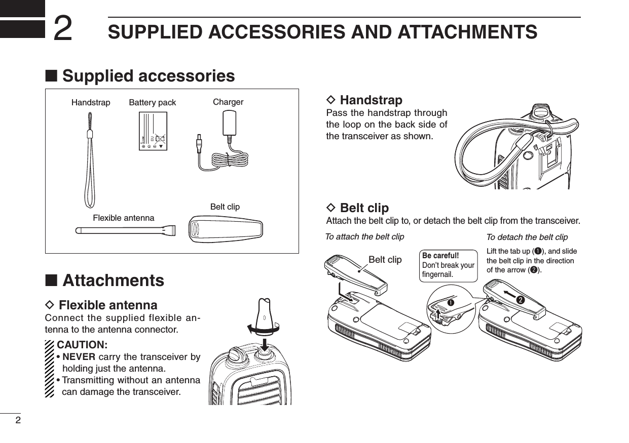
![iiIN CASE OF EMERGENCY RECOMMENDATIONIf your vessel requires assistance, contact other vessels and the Coast Guard by sending a distress call on Channel 16.❍ USING CHANNEL 16DISTRESS CALL PROCEDURE1. “MAYDAY MAYDAY MAYDAY.”2. “THIS IS ……………… ” (name of vessel)3. Your call sign or other indication of the ves-sel.4. “LOCATED AT …………… ” (your position)5. The nature of the distress and assistance required.6. Any other information which might facilitate the rescue.CLEAN THE TRANSCEIVER THOROUGHLY WITH FRESH WATER after exposure to saltwater, and dry it before operat-ing. Otherwise, the transceiver's keys, switches and control-lers may become unusable due to salt crystallization.NOTE: DO NOT submerge the transceiver in water if there is any reason to suspect the waterproof protection may not be effective. For example, in cases where the battery cover or [DC] jack cap rubber seal is damaged, the transceiver/battery cover/[DC] jack cap is cracked or broken, or the transceiver has been dropped, or when the battery cover, antenna or DC Jack cap are detached from the transceiver.BP-266BP-266BP-266](https://usermanual.wiki/ICOM-orporated/334000/User-Guide-1414184-Page-3.png)
![ivRWARNING! NEVER connect the transceiver to an AC outlet. This may pose a fi re hazard or result in an electric shock.RWARNING! NEVER hold the transceiver so that the antenna is closer than 2.5 cm (1 inch) from exposed parts of the body, especially the face or eyes, while transmit-ting. The transceiver will perform best if the microphone is 5 to 10 cm (2 to 4 inches) away from the lips and the trans-ceiver is vertical.CAUTION: NEVER connect the transceiver to a power source other than the BC-199 or BP-266. Such a con-nection will ruin the transceiver.DO NOT use or place the transceiver in direct sunlight or in areas with temperatures below –20°C (–4°F) or above +60°C (+140°F).KEEP the transceiver out of the reach of children.KEEP the transceiver at least 0.9 meters (3.0 ft) away from your vessel’s magnetic navigation compass.BE CAREFUL! The transceiver meets IPX7* require-ments for waterproof protection. However, once the trans-ceiver has been dropped, waterproof protection cannot be guaranteed because of possible damage to the transceiver's case or the waterproof seal.* Only when the flexible antenna, battery cover and [DC] jack cap are securely attached.MAKE SURE the fl exible antenna and battery cover are securely attached to the transceiver, and that the antenna and battery cover are dry before attachment. Exposing the inside of the transceiver to water will result in serious dam-age to the transceiver.Icom, Icom Inc. and the Icom logo are registered trademarks of Icom Incor-porated (Japan) in Japan, the United States, the United Kingdom, Germany, France, Spain, Russia and/or other countries.PRECAUTIONS](https://usermanual.wiki/ICOM-orporated/334000/User-Guide-1414184-Page-5.png)

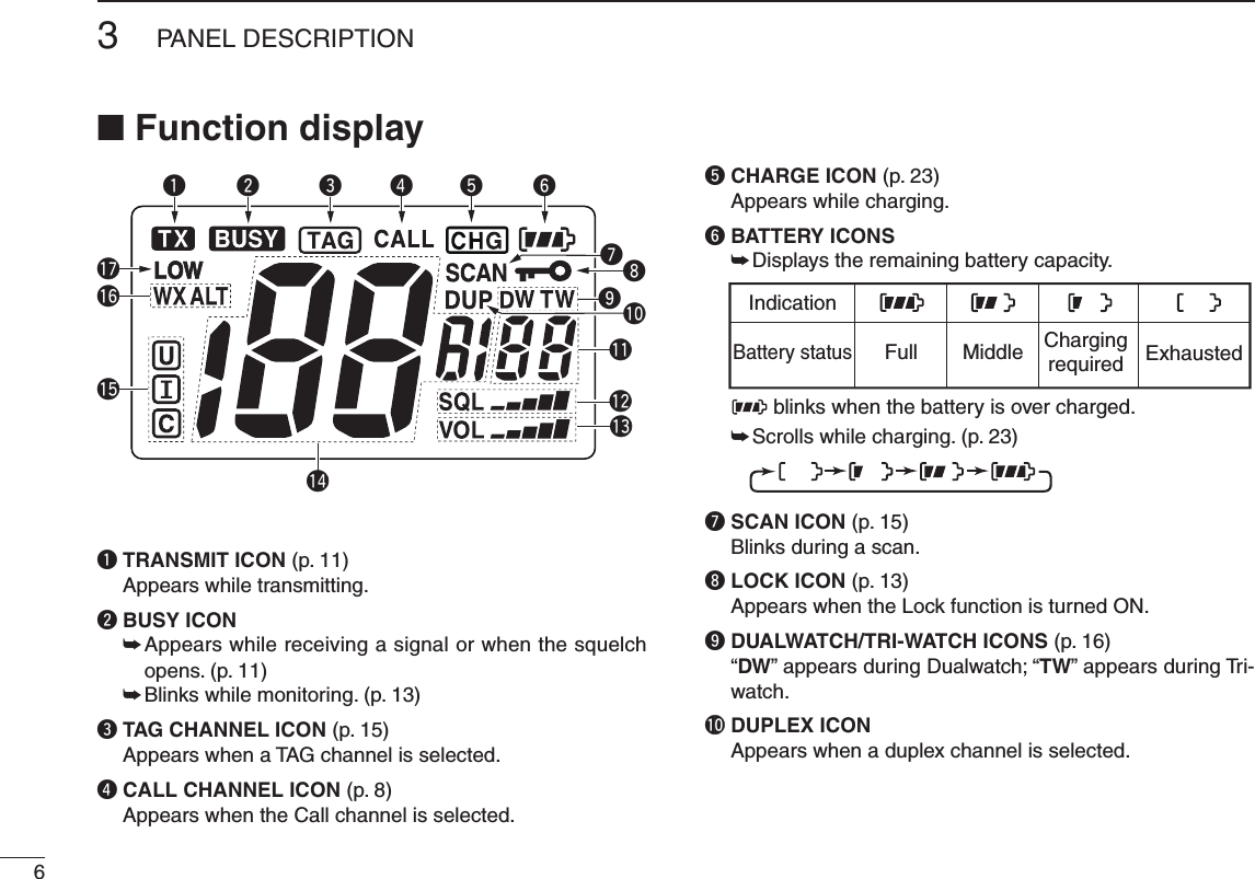
![4PANEL DESCRIPTION3■ Front, top and side panelsq ANTENNA CONNECTOR (p. 2) Connect the supplied antenna here.w DC JACK [DC] (p. 23) Connect the charger or optional cable here. NOTE: Attach the [DC] jack cap when the charger or op-tional cable is not connected. Otherwise, water will get into the transceiver. When attaching the [DC] jack cap, make sure dust or other material does not adhere to the rubber seal. If dust or other material is on the seal when attaching the cap, waterproof protection may not be guaranteed.e PTT SWITCH [PTT] Hold down to transmit; release to receive. (p. 11)r CHANNEL 16 KEY [16 9] ➥ Push to select Channel 16. (p. 8) ➥ Hold down for 1 second to select the Call channel. (p. 8) ➥ When the Call channel is selected, hold down for 3 seconds to enter the Call channel programming mode. (p. 12) ➥ While in the Set mode, push to return to the normal op-erating mode. (p. 17)Functiondisplay (pp. 6, 7)Speakerytreuwq!1oi!0MicrophoneBP-266BP-266BP-266q To remove the [DC] jack cap, rotate it counter clockwise.BP-266BP-266BP-266w Pull the cap up to detach it.BP-266BP-266BP-266](https://usermanual.wiki/ICOM-orporated/334000/User-Guide-1414184-Page-10.png)
![t VOLUME/SQUELCH/MONITOR KEY [VOL/SQL MONI] ➥ Push to enter the volume adjustment mode or the squelch adjustment mode. (p. 10) ➥ Hold down for 1 second to activate the Monitor func-tion. (p. 13) ➥ While holding down this key, hold down [] to turn ON the power and enter the Set mode. (p. 17) ➥ While in the Set mode, push to select an item. (p. 17) ➥ While holding down this key, push [Z] to turn ON the Volume Mute function. Do the same steps again to turn OFF the function. (p. 12) ➥ While holding down this key, push [Y] to turn ON the Volume Loud function. Do the same steps again to turn OFF the function. (p. 12)y SCAN/DUAL KEY [SCAN DUAL] ➥ Push to start or stop a normal or priority scan. (p. 15) ➥ Hold down for 1 second to enter the Dual/Tri-watch mode. (p. 16) ➥ Push to exit the watch mode. (p. 16) ➥ Hold down this key and [Hi/Lo] for 1 second, to activate the AquaQuake function. (p. 13)u UP/DOWN KEYS [Y] or [Z] ➥ Push to select an operating channel. (pp. 8, 9) ➥ While in the Set mode, push to select the setting or value of an item. (p. 17) ➥ Push to check TAG channels or change scanning direc-tion during a scan. (p. 15)i FAVORITE/TAG KEY [FAV TAG] ➥ Push to sequentially select the favorite (TAG) chan-nels, while ignoring untagged channels, in a channel group. (p. 8) ➥ Hold down for 1 second to set or clear the TAG for the displayed channel. (p. 15) ➥ While holding down, turn ON the power to clear or set all TAG channels in the selected channel group. (p. 15)o CHANNEL/WEATHER CHANNEL KEY [CH/WX U/I/C] ➥ Push to switch between a regular channel and a weather channel. (p. 9) ➥ Hold down for 1 second to select the USA, International and Canada channel groups. (p. 9) ➥ Push to return to the previous channel before selecting Channel 16 or the Call channel. (p. 8)!0 POWER KEY [ ] Hold down to turn power ON or OFF.!1 TRANSMIT POWER/LOCK KEY [Hi/Lo ] ➥ Push to select the high or low output power. (p. 11) ➥ Hold down for 1 second to turn the Lock function ON or OFF. (p. 13)53PANEL DESCRIPTION12345678910111213141516Volume adjustment modeNormal operating modeSquelch adjustment modePUSHPUSHPUSHBP-266BP-266BP-266](https://usermanual.wiki/ICOM-orporated/334000/User-Guide-1414184-Page-11.png)
![8BASIC OPERATION4■ Channel selectionIMPORTANT: Prior to using the transceiver for the first time, the battery pack must be fully charged for optimum life and operation (p. 23). To avoid damage to the trans-ceiver, turn OFF the power while charging.D Channel 16Channel 16 is the distress and safety channel. It is used for establishing initial contact with a station, and for emergency communications. Channel 16 is monitored during both Du-alwatch and Tri-watch. While in the standby mode, you must monitor Channel 16.q Push [16] momentarily to select Channel 16.w Push [CH/WX] to return to the channel used before se-lecting Channel 16, or push [Y] or [Z] to select a differ-ent channel.Convenient!While holding down [FAV], push [Y] or [Z] to select the fa-vorite (TAG) channels.• Pushing [FAV] only advances the displayed TAG channel.• The favorite channels are selected using the TAG channel setting. (p. 15)D Channel 9 (Call channel)Each regular channel group has a separate leisure-use Call channel. The Call channel is monitored during Tri-watch. The Call channels can be programmed, and are used to store your most often used channel in each channel group, for quick recall. (p. 12)q Hold down [9] (16) for 1 second to select the Call channel of the selected channel group. • “CALL” and the Call channel number appear.w Push [CH/WX] to return to the channel used before se-lecting the Call channel, or push [Y] or [Z] to select a different channel.PushHold downfor 1 second](https://usermanual.wiki/ICOM-orporated/334000/User-Guide-1414184-Page-14.png)
![D USA, International and Canadian channelsThe transceiver is pre-programmed with 59 USA, 61 Inter-national and 65 Canadian channels. Choose the appropriate channel groups for your operating area.q Push [CH/WX] to select a regular channel. • If a weather channel appears, push [CH/WX] again.w Hold down [U/I/C] (CH/WX) for 1 second to change the channel group. Repeat to advance to the next group. • USA, International and Canadian channel groups can be se-quentially selected.e Push [Y] or [Z] to select a channel. • “DUP” appears for duplex channels. • “A” appears when a simplex channel is selected.D Weather channelsThe transceiver has 10 weather channels. These are used for monitoring broadcasts from NOAA (National Oceanic and Atmospheric Administration).The transceiver can automatically detect a weather alert tone on the selected weather channel while receiving an-other channel, or during a scan. (p. 18)q Push [CH/WX] once or twice to select the Weather chan-nel group. • “WX” appears when a weather channel is selected. • “WX ALT” appears when the Weather Alert function is turned ON. (p. 18)w Push [Y] or [Z] to select a weather channel.94BASIC OPERATION12345678910111213141516Hold downU.S.A. channelsInternational channels Canadian channels for 1 secondPush once or twice.Weather Alert is OFF. Weather Alert is ON.](https://usermanual.wiki/ICOM-orporated/334000/User-Guide-1414184-Page-15.png)
![104BASIC OPERATION■ Adjusting the volume levelThe volume level can be adjusted using [VOL/SQL] and [Y] or [Z].q Push [VOL/SQL] once to enter the volume adjustment mode, then push [Y] or [Z] to adjust the volume level. • The “VOL” icon starts blinking. • The transceiver has 31 volume levels and OFF. • When no key operation is performed for 5 seconds, the trans-ceiver returns to the normal mode.w Push [VOL/SQL] twice to exit the volume adjustment mode.■ Adjusting the squelch levelThe squelch level can be adjusted using [VOL/SQL] and [Y] or [Z].In order to properly receive signals, as well as for the scan to effectively function, the squelch must be adjusted to the proper level.q Push [VOL/SQL] twice to enter the squelch adjustment mode, then push [Y] or [Z] to adjust the squelch level. • The “SQL” icon starts blinking. • The transceiver has 11 squelch levels: OP is completely open; 10 is tight squelch; 1 is loose squelch. • When no key operation is performed for 5 seconds, the trans-ceiver returns to the normal mode.w Push [VOL/SQL] again to exit the squelch adjustment mode.Displays the volume level.Blinks in the volume adjustment mode.Displays the squelch level.Blinks in the squelch adjustment mode.](https://usermanual.wiki/ICOM-orporated/334000/User-Guide-1414184-Page-16.png)
![■ Receiving and transmittingCAUTION: Transmitting without an antenna can damage the transceiver.q Hold down [] to turn ON the power.w Set the volume and squelch levels. You can enter each adjustment mode by pushing [VOL/SQL]. ➥ Enter the squelch adjustment mode, and then push [Z] one or more times to open the squelch. ➥ Enter the volume adjustment mode, and then push [Y] or [Z] to adjust the volume level. ➥ Enter the squelch adjustment mode again, and push [Y] until the noise just disappears.e Push [VOL/SQL] again to exit the squelch adjustment mode.r Push [Y] or [Z] to select a desired channel. • When receiving a signal, “ ” appears and audio is heard from the speaker. • You may want to further adjust the audio level.t Push [Hi/Lo] to select the output power if necessary. • “LOW” appears when low power is selected; no icon is displayed when high power is selected. • Choose low power for short range communications; choose high power for longer distance communications. • Some channels are for only low power communication.y Hold down [PTT] to transmit, then speak into the microphone. • “ ” appears. • Channel 70 cannot be used for transmission.u Release [PTT] to receive.IMPORTANT: To maximize the readability of your trans-mitted signal, pause for a second after pushing [PTT], hold the microphone 5 to 10 cm (2 to 4 inches) from your mouth and speak into the microphone at a normal voice level.NOTE: To conserve battery power, the transceiver’s Power Save function automatically activates when no sig-nal is received for 5 seconds.For U.S.A version: To prevent prolonged transmission, a time-out timer cuts OFF after 5 minutes of continuous transmission.114BASIC OPERATION12345678910111213141516BP-266Microphonet Set output power.q Power ON.y Push to transmit.u Release to receive.rSet channel.Enter the volume and squelch ad-justment mode.ww Adjust the volume and squelch level.BP-266BP-266](https://usermanual.wiki/ICOM-orporated/334000/User-Guide-1414184-Page-17.png)
![124BASIC OPERATION■ Call channel programmingThe Call channel is used to access Channel 9 (default). However, you can program the Call channel with your most often-used channel in each channel group, for quick recall.q Hold down [U/I/C] (CH/WX) for 1 second, one or more times, to select the desired channel group to be pro-grammed (USA, International or Canada). (p. 9)w Hold down [9] (16) for 1 second to select the Call channel of the selected channel group. • “CALL” and the Call channel number appear.e Hold down [9] (16) again for 3 sec-onds (until a long beep changes to 2 short beeps) to enter the Call channel programming mode. • The channel number starts blinking.r Push [Y] or [Z] to select the desired channel.t Push [9] (16) to program the dis-played channel as the Call channel. • The channel number stops blinking.■ Volume Loud functionThe Volume Loud function temporarily maximizes the vol-ume level.This function has no effect when the volume level is 31.q While holding down [VOL/SQL], push [Y] to turn ON the Volume Loud function. • The volume level is set to the maximum level (level 31). • The bars of the volume level icon repeatedly appear in ascend-ing order.w Push [VOL/SQL] and [Y] again to turn OFF the Volume Loud function.■ Volume Mute functionThe Volume Mute function temporarily mutes the audio out-put.This function has no effect when the volume level is OFF.q While holding down [VOL/SQL], push [Z] to turn ON the Volume Mute function. • The volume level is set to the minimum level (OFF). • The “VOL” icon blinks.w Push [VOL/SQL] and [Z] again to turn OFF the Volume Mute function.](https://usermanual.wiki/ICOM-orporated/334000/User-Guide-1414184-Page-18.png)
![■ Lock functionThis function electronically locks all keys (except for [PTT], [VOL/SQL], [MONI] (VOL/SQL), [] (Hi/Lo) and [Y] or [Z]*) to pre-vent accidental changing of the channel and function access.* Only in the volume or squelch adjustment mode, and volume loud and Volume Mute functions.➥ Hold down [ ] (Hi/Lo) for 1 second to turn the Lock function ON and OFF.■ Monitor functionThe Monitor function opens the squelch. The monitor key ac-tion can be selected in the Set mode. (p. 19)➥ The Monitor function is activated by holding down [MONI] (VOL/SQL). • “ ” blinks and the squelch opens.■ Automatic backlightingThis function lights the function display and keys, and is con-venient for night-time operation. The automatic backlighting can be activated in the Set mode. (p. 20)➥ Push any key except for [PTT] to turn ON the backlight. • The backlight is automatically turned OFF after 5 seconds of inactivity.■ AquaQuake Water Draining functionThe AquaQuake Water Draining function removes water from the speaker grill. Without this function, water may muffl e the sound coming from the speaker. The transceiver makes a vibrating sound when this function is activated.➥ Hold down both [SCAN] and [Hi/Lo]. • A low vibration tone sounds for 9 seconds to drain water, re-gardless of the volume level setting. • The transceiver does not accept key operations while the AquaQuake Water Draining function is activated. 134BASIC OPERATION12345678910111213141516Appears while the Lock function is activated.Hold downfor 1 secondBlinks while the monitor function is activated.Hold down](https://usermanual.wiki/ICOM-orporated/334000/User-Guide-1414184-Page-19.png)
![■ Setting TAG channelsFor more efficient scanning, add the desired channels as TAG channels, or clear the TAG on unwanted channels.Channels that are not tagged will be skipped while scan. TAG channels can be independently assigned to each USA, International and Canada channel group.q Hold down [U/I/C] (CH/WX) for 1 second one or more times to select the desired channel group.w Select the desired channel to be set as a TAG channel.e Hold down [TAG] (FAV) for 1 second to set the displayed channel as a TAG channel. • “ ” appears on the display.r To cancel a TAG channel setting, hold down [TAG] (FAV) for 1 second. • “ ” disappears.✔ Clearing (or setting) all tagged channelsWhile holding down [TAG] (FAV), turn ON the power to clear all TAG channels in the selected channel group.• Repeat above procedure to set all channels as TAG channels (when no TAG channel has been set.)■ Starting a scanSet the Weather Alert function, Priority Scan function, Scan Resume Timer and Auto Scan function in advance, in the Set mode. (pp. 18, 19)q Hold down [U/I/C] (CH/WX) for 1 second one or more times to select a desired channel group. • When the Weather Alert function is in use, select a desired weather channel using [CH/WX] and [Y] or [Z]. (p. 9)w Push [SCAN] to start a priority or normal scan. • “SCAN” blinks while scanning. • “16” appears on the sub channel readout during a priority scan. • When a signal is received, the scan pauses until the signal disappears, or resumes after pausing 5 seconds, depending on the Set mode setting. • Push [Y] or [Z] to sequentially select TAG channels, change the scanning direction or manually resume the scan.e To stop the scan, push [SCAN] again. • “SCAN” disappears. • Pushing [PTT], [16], [CH/WX] or [FAV] also stops the scan.155SCAN OPERATION12345678910111213141516[Example]: Starting a normal scan.PushBlinks BlinksScanning starts When a signal is receivedAppears](https://usermanual.wiki/ICOM-orporated/334000/User-Guide-1414184-Page-21.png)
![16DUALWATCH/TRI-WATCH6■ DescriptionDualwatch monitors Channel 16 while you are receiving on another channel; Tri-watch monitors Channel 16 and the Call channel while receiving another channel. Dualwatch/Tri-watch are convenient for monitoring Channel 16 when you are operating on another channel.■ Operationq Select Dualwatch or Tri-watch in the Set mode. (p. 19)w Select the desired channel.e Hold down [DUAL] (SCAN) for 1 second to start Dual-watch or Tri-watch, depending on the Set mode setting. • “DW” blinks during Dualwatch; “TW” blinks during Tri-watch. • A beep tone sounds when a signal is received on Channel 16. • Tri-watch switches to Dualwatch when receiving a signal on the Call channel.r To cancel Dualwatch/Tri-watch, push [DUAL] (SCAN) again.• If a signal is received on Channel 16, Dualwatch/Tri-watch pauses on Channel 16 until the signal disappears.• If a signal is received on the Call channel during Tri-watch, Tri-watch becomes Dualwatch until the signal dis-appears.• To transmit on the selected channel during Dualwatch/Tri-watch, Hold down [PTT].DualwatchDUALWATCH/TRI-WATCH SIMULATIONTri-watchCallchannelCh 88Ch 16 Ch 88 Ch 16 Ch 88 Ch 9[Example]: Operating Tri-watch on INT channel 07.Tri-watch starts.A signal is received on the Call channel.The signal received on Channel 16 takes priority.Tri-watch resumes after the signal disappears.](https://usermanual.wiki/ICOM-orporated/334000/User-Guide-1414184-Page-22.png)
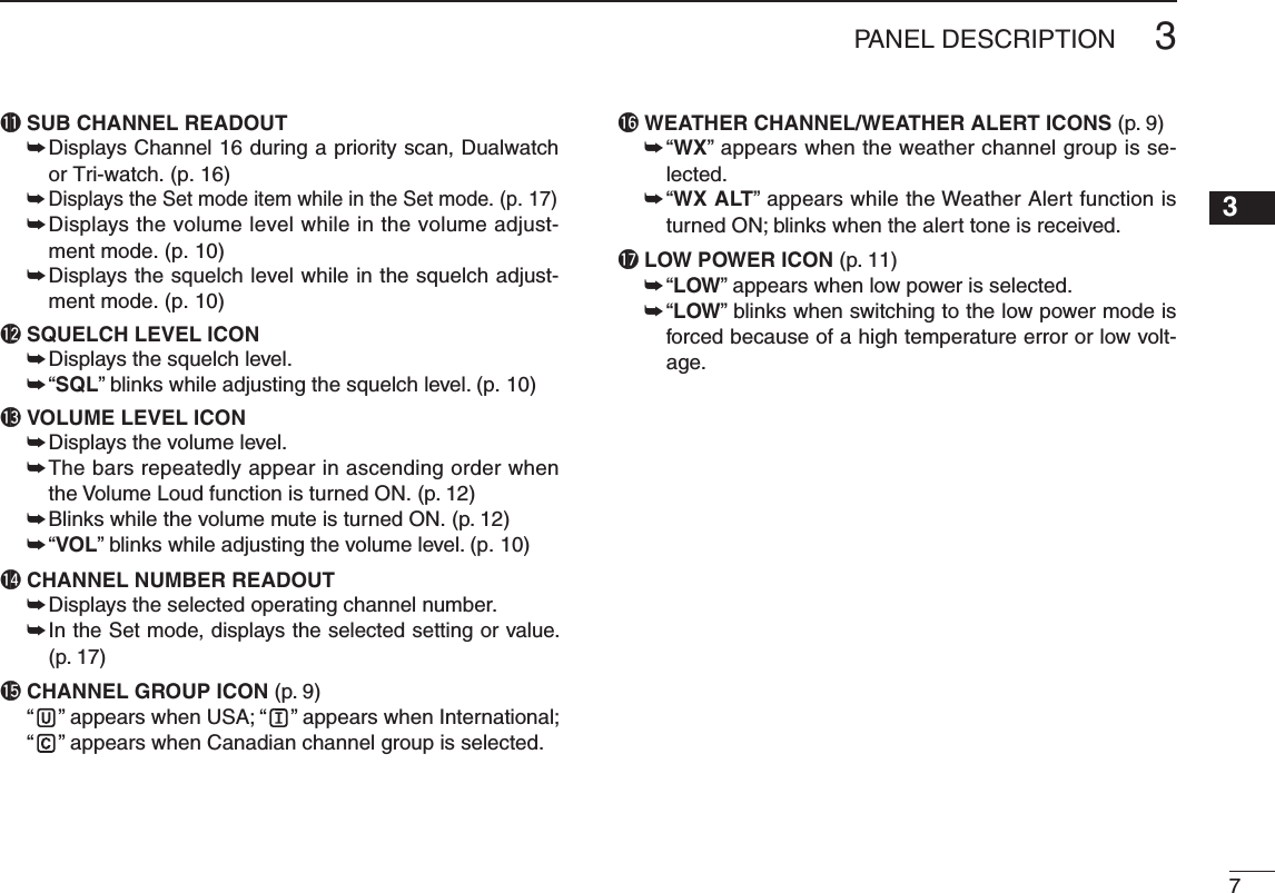
![■ Set mode programmingThe Set mode is used to change the settings of transceiver's functions: Beep Tone function, Weather Alert function, Prior-ity Scan function, Scan resume timer, Auto Scan function, Dual/Tri-watch function, Monitor key action, Automatic back-lighting, LCD contrast setting and Power Save function.D Set mode operationq Turn OFF the power.w While holding down [VOL/SQL], turn ON the power to enter the Set mode. • “bP” appears.e Push [VOL/SQL] to select a desired item. Or while holding down [VOL/SQL], push [Y] or [Z] also selects an item.r Push [Y] or [Z] to select a desired option of the item.t To exit the Set mode, push [16].177SET MODE12345678910111213141516SET MODE ITEMS (The display shows the current settings, and the selected item is displayed in the dotted circle.)• Auto scanStarting item• Beep tone • Scan resume timer• Dual/Tri-watch• Automatic backlighting• Power save• LCD contrast • Monitor key action• Priority scan• Weather Alert: Push + : Push Pushor +](https://usermanual.wiki/ICOM-orporated/334000/User-Guide-1414184-Page-23.png)
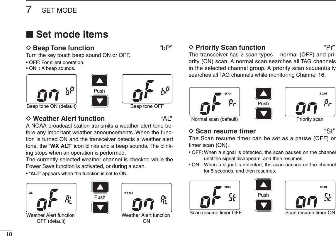
![D Auto Scan function “AS”The Auto Scan function automatically starts a normal or priority scan when no signal is received, and no operation is performed for 30 seconds.D Dual/Tri-watch function “dt”Set the watch type to Dualwatch or Tri-watch. (p. 16)D Monitor key action “Sq”The monitor key temporarily opens the squelch. This item sets the key action.• Pu (PUSH) : The Monitor function is activated by holding down [MONI] (VOL/SQL). The squelch stays open while holding down the key.• Ho (HOLD) : The Monitor function is activated by holding down [MONI] (VOL/SQL) for 1 second. The squelch stays open until any key is pushed.197SET MODE12345678910111213141516Auto scan OFF (default) Auto scan ONPushDualwatch function(default)Tri-watch functionPushPush setting (default) Hold settingPush](https://usermanual.wiki/ICOM-orporated/334000/User-Guide-1414184-Page-25.png)
![207SET MODED Automatic backlighting “bL”This function is convenient for night-time operation. The backlight can be selected from ON and OFF.• The backlight is automatically activated when any key except [PTT] is pushed.• The backlight is automatically turned OFF after 5 seconds of inac-tivity.D LCD contrast setting “LC”Set the LCD contrast level to High contrast or Low contrast. The LCD contrast level has little effect during indoor use.D Power Save function “PS”The Power Save function reduces current drain by turning OFF the receiver circuit for preset intervals. • OFF : The Power Save function is turned OFF.• ON : The Power Save function is turned ON. The Power Save function will be activated when no signal is received, and no operation is performed for 5 secondsAuto backlighting ON(default)Auto backlighting OFFPushHigh contrast (default) Low contrastPushPower Save ON (default)Power Save OFFPush](https://usermanual.wiki/ICOM-orporated/334000/User-Guide-1414184-Page-26.png)
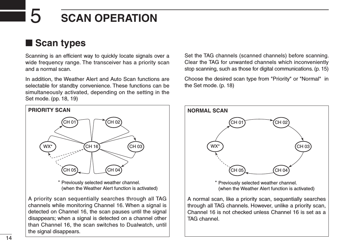
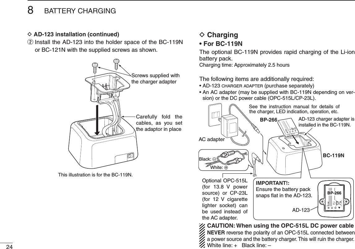
![238BATTERY CHARGING12345678910111213141516■ Supplied battery chargerD ChargingDo not use a charger other than the specifi ed one.q Turn OFF the transceiver's power.w Connect the charger as shown below. • “ ” appears, and the battery icon scrolls while charging.e The charging is completed in approximately 8.5 hours, depending on the remaining capacity before charging. • “” and “ ” appear, and “FL” is also displayed on the function display when charging is completed.Charger[DC] jackPower OFFBP-266BP-266BP-266NOTE: “ ” and “ ” blink, and “Er” is also displayed on the function display, when the battery pack is not attached.■ Optional battery chargerDo not place the charger on a surface with any vibration. Otherwise the battery pack might come out of the charger, or the charger itself might fall.D AD-123 installationThe AD-123 CHARGER ADAPTER must be installed into the BC-119N DESKTOP CHARGER or BC-121N MULTI-CHARGER before charging.q Connect the AD-123 and the BC-119N or BC-121N as shown.BP-266BP-266BP-266AD-123BP-266BP-266PlugsSocketsThis illustration is for the BC-119N.BP-266](https://usermanual.wiki/ICOM-orporated/334000/User-Guide-1414184-Page-29.png)
![258BATTERY CHARGING12345678910111213141516AD-123 chargeradapters are installedin each slot.AC adapter(Purchased separately)DC power cable (OPC-656)(Connect to a DC power supply; 13.8 V/at least 7 A)xx See the instruction manual for details of the charger, LED indication, operation, etc.BP-266BP-266BP-266BP-266IMPORTANT!:Ensure the battery packsnaps flat in the AD-123.AD-123BP-266BP-266BP-266BC-121N• For BC-121NThe optional BC-121N allows up to six battery packs to be charged simultaneously.Charging time: Approximately 2.5 hoursThe following items are additionally required.• Six AD-123 CHARGER ADAPTERS (purchase separately)• An AC adapter or the DC power cable (OPC-656)D Charging from a cigarette lighter socketUse the optional CP-24 CIGARETTE LIGHTER CABLE charge from a cigarette lighter socket.Charging time: Approximately 8.5 hours.• CAUTION: BE SURE to remove the CP-24 from the ciga-rette lighter socket when charging is finished, because a slight current still fl ows in the CP-24 and will drain the ve-hicle’s battery.• The CP-24 is equipped with a 2 A fuse. If the fuse blows, de-termine and fi x the problem, then replace it with a new rated fuse.BP-266BP-266BP-266[DC] jackPower OFFTo a cigarette lighter socket (12/24 V DC)CP-24Fuse (2 A /250 V)BP-266BP-266BP-266](https://usermanual.wiki/ICOM-orporated/334000/User-Guide-1414184-Page-31.png)
![26TROUBLESHOOTING9PROBLEM POSSIBLE CAUSE SOLUTION REF.The transceiver does not turn ON.• The battery is exhausted.• The battery pack is not correctly in-serted.• Recharge the battery pack.• Correctly insert the battery pack.p. 23p. 3No sound from speaker. • The squelch level is too high.• Volume level is too low.• Speaker has been exposed to water.• Set the squelch level to the threshold level.• Adjust the audio level to a suitable level.• Remove water from the speaker grill.p. 10p. 10p. 13Transmitting is impossible, or high power can not be se-lected.• Some channels are limited to low power or only receive.• The output power is set to low.• The battery is exhausted.• Change the channel.• Push [Hi/Lo] to select high power.• Recharge the battery pack.pp. 8, 9, 27p. 11p. 23The displayed channel cannot be changed.• The Lock function is activated. • Hold down [] (Hi/Lo) for 1 second to turn OFF the function.p. 13Scan does not start • “TAG” channels are not programmed. • Set desired channels as “TAG” channels.p. 15No beep sounds. • Beep Tone function is turned OFF. • Turn ON the Beep Tone in the set mode. p. 18](https://usermanual.wiki/ICOM-orporated/334000/User-Guide-1414184-Page-32.png)