ICOM orporated 352100 VHF Transceiver User Manual
ICOM Incorporated VHF Transceiver
UserManual.wiki
>
ICOM orporated
>
352100 User Manual
>
User Manual
Contents
1.
User Manual
2.
User Manual_Cut Antenna
User Manual
Navigation menu
Upload a User Manual
Namespaces
Wiki Guide
HTML
PDF
Info
Views
User Manual
Discussion / Help
Navigation
![iiR DANGER! NEVER short the terminals of the bat-tery pack.R DANGER! Use and charge only specified Icom bat-tery packs with Icom radios or Icom chargers. Only Icom bat-tery packs are tested and approved for use with Icom radios or charged with Icom chargers. Using third-party or coun-terfeit battery packs or chargers may cause smoke, fire, or cause the battery to burst.R WARNING! NEVER hold the transceiver so that the antenna is very close to, or touching exposed parts of the body, especially the face or eyes, while transmitting. The transceiver will perform best if the microphone is 5 to 10 cm (2 to 4 inches) away from the lips and the transceiver is vertical.R WARNING! NEVER operate the transceiver with a headset or other audio accessories at high volume levels. Hearing experts advise against continuous high volume op-eration. If you experience a ringing in your ears, reduce the volume level or discontinue use.R WARNING! NEVER operate the transceiver while driving a vehicle. Safe driving requires your full attention—anything less may result in an accident.CAUTION: MAKE SURE the flexible antenna, bat-tery pack and jack cover are securely attached to the trans-ceiver, and that the antenna and battery pack are dry before attachment. Exposing the inside of the transceiver to dust or water will result in serious damage to the transceiver.DO NOT operate the transceiver near unshielded electri-cal blast ing caps or in an explosive atmosphere.DO NOT push [PTT] when not actually intending to transmit.DO NOT use or place the transceiver in direct sunlight or in areas with temperatures below –30°C (–22°F) or above +60°C (+140°F).The basic operations, transmission and reception of the trans-ceiver are guaranteed within the specified operating tempera-ture range. However, the LCD display may not be operate correctly, or show an indication in the case of long hours of operation, or after being placed in extremely cold areas.DO NOT modify the transceiver. The transceiver warranty does not cover any problems caused by unauthorized modi-fication.DO NOT use harsh solvents such as benzine or alcohol when cleaning, as they will damage the transceiver surfaces.BE CAREFUL! The transceiver will become hot when operating it continuously for long periods of time.PRECAUTIONS](https://usermanual.wiki/ICOM-orporated/352100.User-Manual/User-Guide-2128342-Page-3.png)
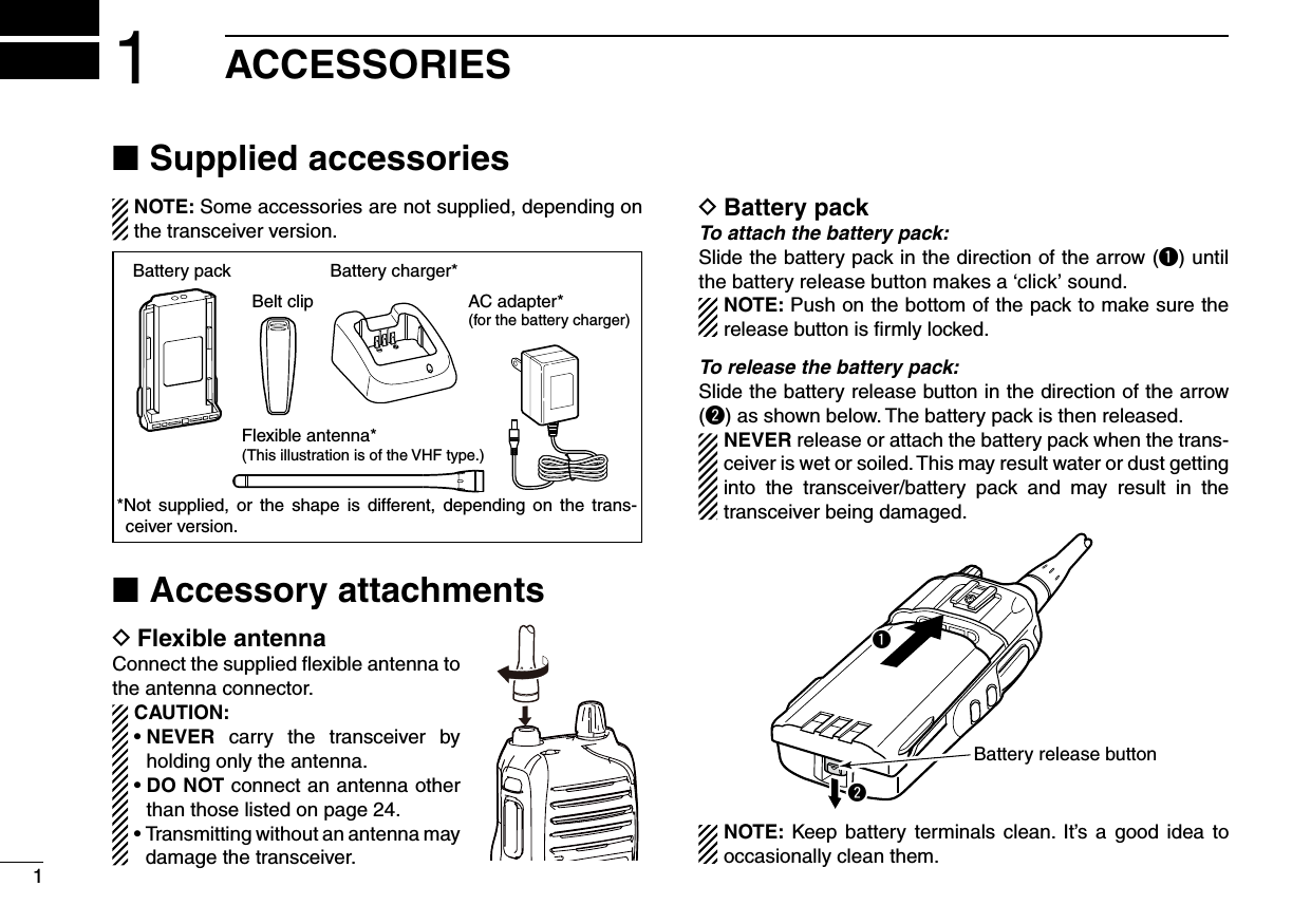
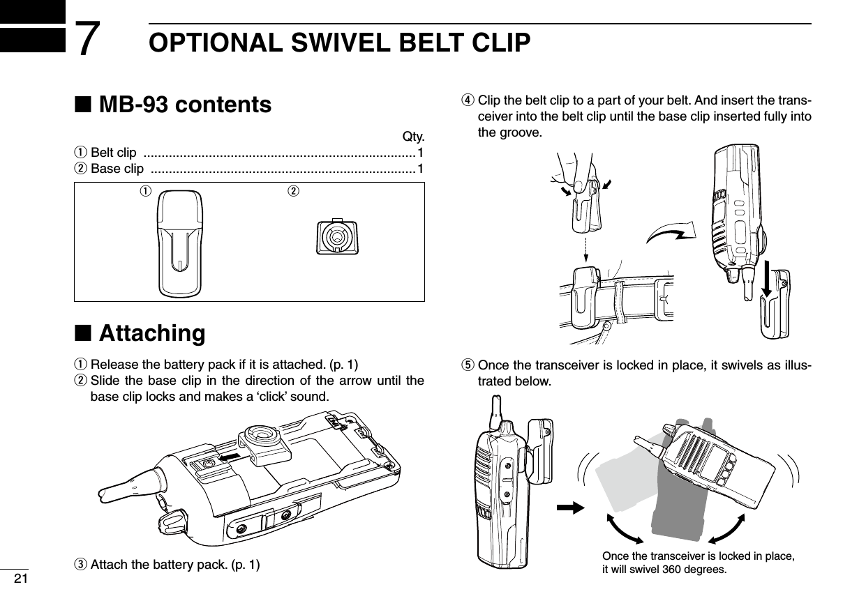
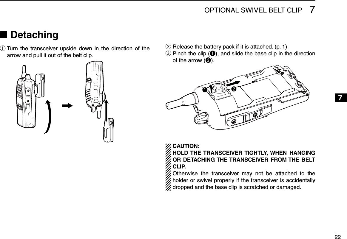
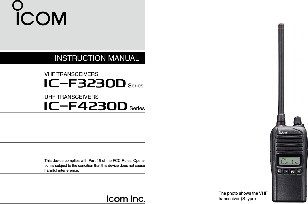
![21ACCESSORIES12345678910111213141516Belt clip DTo attach the belt clip:Remove the battery pack if it is attached. q w Slide the belt clip in the direction of the arrow until the belt clip is locked and makes a ‘click’ sound.To detach the belt clip: Remove the battery pack if it is attached. q Pinch the clip ( wq), and slide the belt clip in the direction of the arrow (w).qwJack cover DTo attach the jack cover:Attach the jack cover to the [MIC/SP] jack. ( qq)Tighten the screws. ( ww)w[MIC/SP] jackJack coverqCAUTION:• Attach the jack cover when the optional equipment is not used.• Use only the supplied screws.To detach the jack cover: Unscrew the screws using a phillips qscrewdriver. (q) Detach the jack cover to connect the woptional equipment. (w)qqw](https://usermanual.wiki/ICOM-orporated/352100.User-Manual/User-Guide-2128342-Page-7.png)
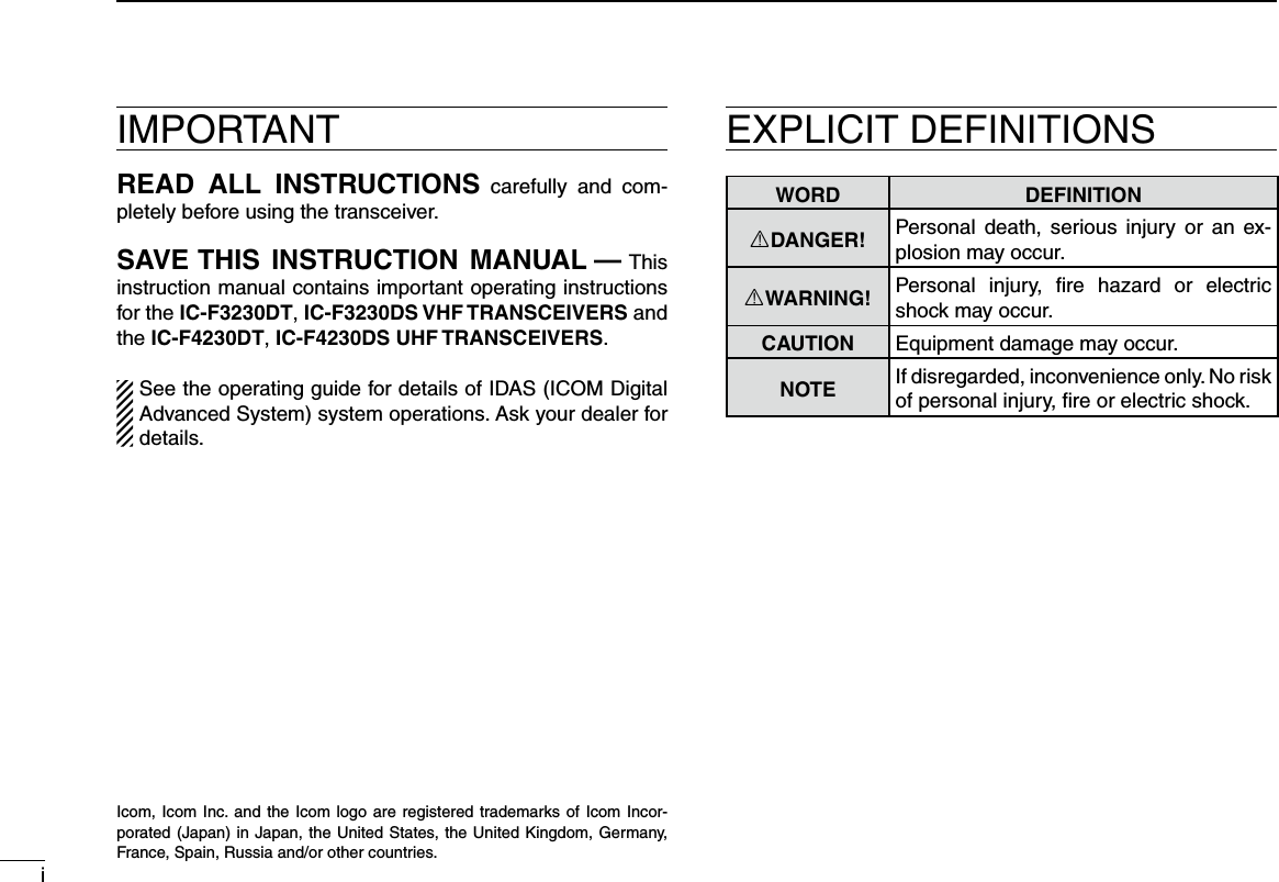
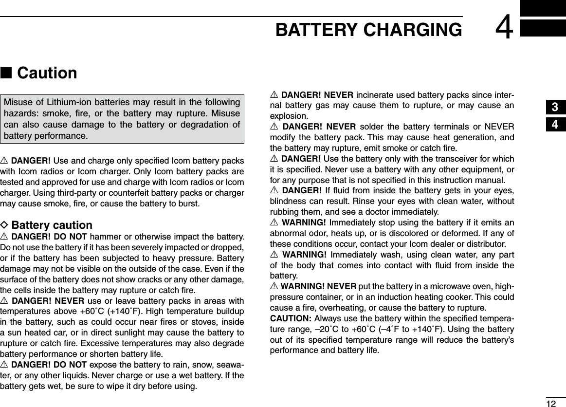
![32PANEL DESCRIPTIONFront panel ■qwreouyMicrophoneSpeakertiq ANTENNA CONNECTORConnects the supplied antenna.w DEALER-PROGRAMMABLE KEY [Emer] A desired function can be programmed by your dealer. (p. 5)e DEALER-PROGRAMMABLE KEY [Side1] A desired function can be programmed by your dealer. (p. 5)r PTT SWITCH [PTT]Hold down to transmit, release to receive.t DEALER-PROGRAMMABLE KEYS [Side2]/[Side3]Desired functions can be independently programmed by your dealer. (p. 5)y DEALER-PROGRAMMABLE KEYS [P0] to [P3]Desired functions can be independently programmed by your dealer. (p. 5)u FUNCTION DISPLAY (p. 4) Displays a variety of information such as an operating channel number, channel name, User Set mode contents, and so on.i EXTERNAL MICROPHONE/SPEAKER JACKConnect an optional equipment. NOTE: Connect or disconnect the optional equipment after the transceiver is turned OFF.Jack coverNOTE: Attach the jack cover when optional equipment is not used. See (p. 2) for details.o VOLUME CONTROL [VOL]Rotate to turn the power ON or OFF and to adjust the au-dio level.](https://usermanual.wiki/ICOM-orporated/352100.User-Manual/User-Guide-2128342-Page-8.png)
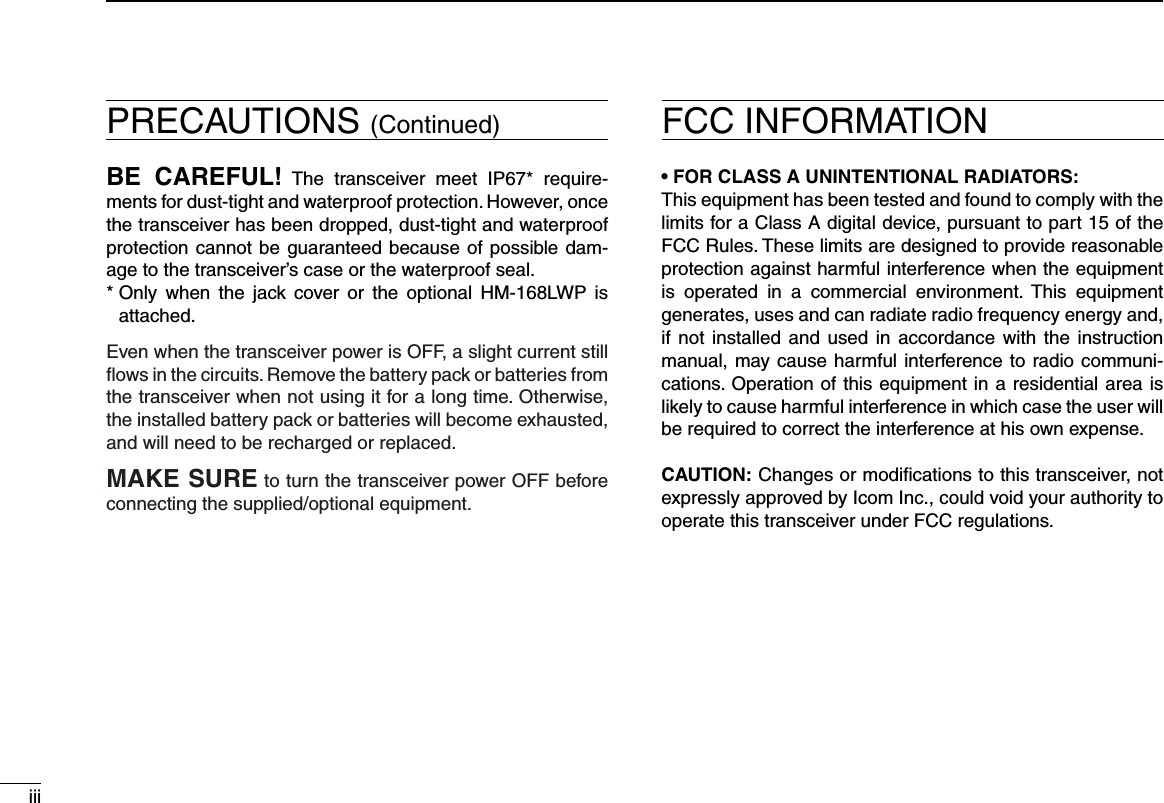
![42PANEL DESCRIPTION12345678910111213141516Function display ■yq iutrewo!0q TRANSMIT ICONAppears while transmitting.w BUSY ICONAppears while the channel is busy (receiving).e SIGNAL STRENGTH ICONShows the relative receive signal strength level.Weak Receive Signal level Strong About “ ” icon for the Trunking mode Disappears while in a no service area. ➥ Blinks while registering to a repeater. ➥ Appears when registration is completed. ➥r LOW POWER ICONAppears when low output power is selected. • When the battery power decreases to a specied level, low power is automatically selected.t AUDIBLE ICON In the analog mode, appears when the CTCSS (DTCS) ➥squelch mute is released while holding down [Monitor]. In the digital mode, appears while holding down [Moni- ➥tor].y ENCRYPTION ICON In the digital mode, appears when the encryption function is activated.u BELL ICONIn the digital mode, appears/blinks when an SDM (Short Data Message), Status Call or Call Alert is received, de-pending on the preprogramming.i KEY LOCK ICONAppears when the Key lock function is ON.o BATTERY ICONAppears or blinks when the battery power decreases to a specified level.!0 ALPHANUMERIC DISPLAYDisplays an operating channel number, channel name, User Set mode contents, and so on.](https://usermanual.wiki/ICOM-orporated/352100.User-Manual/User-Guide-2128342-Page-9.png)
![52PANEL DESCRIPTIONProgrammable function keys ■The following functions can be assigned to [Emer], [Side1], [Side2], [Side3], [P0], [P1], [P2] and [P3] programmable function keys. Consult your Icom dealer or system operator for details con-cerning your transceiver’s programming.CH UP AND DOWNAs described in the following topics, after pushing a pro-grammed key, push [CH Up] or [CH Down] to select an op-tion, setting, and so on.ZONEPush this key, then select the desired zone using [CH Up]/ [CH Down]. What is a “zone”?— Certain channels are grouped to-gether and assigned to a zone, according to their intended use. For example, ‘Staff A’ and ‘Staff B’ are assigned to a “Business” zone, and ‘John’ and ‘Cindy’ are assigned to a “Private” zone.SCAN START/STOPPush to start and cancel a scan. ➥ • When a scan is started with the Power ON Scan or Automatic scan function, push this key to cancel it. The cancelled scan re-sumes after a preprogrammed time period. ➥ Hold down this key for 1 second to display the scan group, then push [CH Up] or [CH Down] to select the desired group.SCAN ADD/DEL (TAG) Push to add the channel to, or delete it from, the current ➥scan group. 1. Push to display the scan group, then push [CH Up] or [CH Down] to select the desired one. 2. Push to add the channel to, or delete it from, the selected scan group. 3. Hold down for 1 second to exit the scan list selection mode. While a scan is paused on a non-priority channel, push this ➥key to delete the selected channel from the scan group. Depending on the setting, the cleared channel may be automatically added to the scan group again after the scan is cancelled.](https://usermanual.wiki/ICOM-orporated/352100.User-Manual/User-Guide-2128342-Page-10.png)
![62PANEL DESCRIPTION2PRIORITY A CHANNEL, PRIORITY B CHANNELPush to select the Priority A or Priority B channel.PRIORITY A CHANNEL (REWRITE),PRIORITY B CHANNEL (REWRITE)Push to select the Priority A or Priority B channel. ➥ Hold down [Prio A (Rewrite)] or [Prio B (Rewrite)] for ➥1 second to assign the operating channel to Priority A or Priority B channel, respectively.MEMORY CHANNELS 1, 2, 3, 4Push to directly select memory channel 1, 2, 3 or 4, if pro-grammed.Consult your dealer for details.MONITOR Push to turn the CTCSS (DTCS) squelch mute ON or OFF. LIGHTPush to turn ON the backlight for about 5 seconds, when the backlight function is set to “OFF” in the User Set mode.LOCK Hold down this key until “LOCK ON” is displayed to elec- ➥tronically lock all programmable keys except the following: [Moni], [Lock], [Emergency]*, [Surveillance], [Siren], [Lone Worker]*, [Light] and [Shift]. * For digital operation. See the operating guide for details To turn OFF the Key Lock function, hold down this key until ➥“LOCK OFF” is displayed.HIGH/LOWPush to select the transmit output power temporarily or per-manently, depending on the preprogramming.• Ask your dealer for the output power level for each selection.TALK AROUNDPush to turn the Talk Around function ON or OFF.• The Talk Around function equalizes the transmit frequency to the receive frequency for transceiver-to-transceiver communication.WIDE/NARROWPush to toggle the IF bandwidth between wide and narrow. SURVEILLANCEPush to turn the surveillance function ON or OFF.When this function is turned ON and a signal is received, the beep is not heard and the LED does not light, even if a key is pushed.](https://usermanual.wiki/ICOM-orporated/352100.User-Manual/User-Guide-2128342-Page-11.png)
![72PANEL DESCRIPTIONProgrammable function keys (Continued) ■SIRENHold down for 1 second to sound the siren.This function can be used for situations other than an emer-gency alert, such as a security alarm for example.• The siren can be stopped only by turning OFF the transceiver power.USER SET MODE Hold down for 1 second to enter the User Set mode. ➥ • While in the User Set mode, push this key to select an item*, and change the value or setting by pushing [CH Up] or [CH Down]. * Selectable items may differ, depending on the preprogram-ming. Hold down this key for 1 second again to exit the User Set ➥mode.ANNOUNCEPush to turn the Channel Announce function ON or OFF.When this function is turned ON, the transceiver announces the channel number when it is selected.RESETPush to return to the normal operating mode. ➥ While in the audible mode, push to return to the inaudible ➥mode.NOTE: See the operating guide for the [Reset] key opera-tion in the digital mode.SHIFTPush to toggle the Normal mode key functions and the Shift mode key functions.• When the Shift mode is selected, the display briey shows “SHIFT ON.” When the Normal mode is selected, the display briefly shows “SHIFT OFF.”](https://usermanual.wiki/ICOM-orporated/352100.User-Manual/User-Guide-2128342-Page-12.png)
![83BASIC OPERATION12345678910111213141516Turning power ON ■Prior to using the transceiver for the first time, the battery pack must be fully charged for optimum life and operation. (p. 12)Rotate [VOL] to turn ON the power. q w If the transceiver is programmed for a start up password, input the digit codes as directed by your dealer. • The 10-keypad may be used for password input, depending on the transceiver’s version: • The keys in the table below can be used for password input. • The transceiver detects numbers in the same block as identical. Therefore “01234” and “56789” are the same.KEYNUMBER 0549382716[Side3][P0]/[P1]/[P2]/[P3]Side3[VOL] e When the “PASSWORD” indication does not clear after in-putting 4 digits, the input code number may be incorrect. Turn the power off and start over in this case.Battery type selection DThe battery type must be selected according to the attached battery type when turning ON the transceiver.Ask your dealer for details.Turn OFF the power. q While pushing and holding [Emer] and [PTT], turn ON wthe power by rotating [VOL] to toggle the attached battery type. • After the display appears, release [Emer] and [PTT]. • “DRY BATT” is displayed for about 3 seconds then “L” appears when the battery case use is selected. In this case, the transmit output power is low. • “LI-ION” is displayed for about 3 seconds when the Lithium-ion battery use is selected.[VOL][PTT][Emer]Dry battery modeAppears](https://usermanual.wiki/ICOM-orporated/352100.User-Manual/User-Guide-2128342-Page-13.png)
![93BASIC OPERATIONChannel selection ■Several types of channel selections are available. Methods may differ, depending on your system set up.NON-ZONE TYPE:To select the desired operating channel:Push [CH Up] or [CH Down]. ➥Push one of [MR-CH 1] to [MR-CH 4]. ➥ Push one of these keys, [Prio A], [Prio B], [Prio A (Re- ➥write)] or [Prio B (Rewrite)].ZONE TYPE:To select the desired operating channel:Push [Zone], then push [CH Up] or [CH Down]. ➥VOTING OPERATION:The transceiver automatically starts scanning when a zone, specified for the voting operation, is selected.The voting scan detects the S-meter of the repeater and au-tomatically selects the strongest station.AUTOMATIC SCAN TYPE:Channel setting is not necessary for this type. When turning ON the power, the transceiver automatically starts scanning. Scanning stops when a signal is received.NOTE: If the Move to Priority A channel at Power ON func-tion is turned ON, the transceiver selects the Priority A channel at Power ON, and then starts scanning. (p. 11)](https://usermanual.wiki/ICOM-orporated/352100.User-Manual/User-Guide-2128342-Page-14.png)
![103BASIC OPERATION3Receiving and transmitting ■CAUTION: Transmitting without an antenna may damage the transceiver. See page 1 for accessory attachments.Receiving:Rotate [VOL] to turn ON the power. q Push [CH Up] or [CH Down] to sequentially select the con- wventional system channel. e When receiving a call, adjust the audio output level to a comfortable listening level.Transmitting:Wait for the channel to become clear to avoid interference. While pushing and holding [PTT], speak into the micro- qphone at a normal voice level.Release [PTT] to return to receive. wIMPORTANT: To maximize the readability of your signal;1. Pause briefly after pushing [PTT].2. Hold the microphone 5 to 10 cm (2 to 4 inches) from your mouth, then speak at a normal voice level.Transmitting notes D• Transmit inhibit function The transceiver has several inhibit functions which restrict transmission under the following conditions: - The channel is busy. However, depending on the pre-programmed settings, you can transmit when the call includes an unmatching (or matching) CTCSS (DTCS), RAN code*, or Individual or Talkgroup ID*. * Digital operation only - The selected channel is a ‘receive only’ channel.• Time-out timer If continuous transmission exceeds the preprogrammed time-out timer limit, the transmission is cut off.• Penalty timer After the transmission is cut off by the time-out timer, trans-mission is further inhibited for the preprogrammed penalty timer period.](https://usermanual.wiki/ICOM-orporated/352100.User-Manual/User-Guide-2128342-Page-15.png)
![113BASIC OPERATIONUser set mode ■The User Set mode allows you to set seldom-changed set-tings. If the transceiver has [User Set Mode] assigned to it, you can “customize” the transceiver operation to suit your preferences and operating style.Entering the User Set mode: Hold down [User Set Mode] for 1 second to enter the User qSet mode. Push [User Set Mode] several times to select the appro- wpriate item. Then push [CH Up] or [CH Down] to set the desired level or condition. • Selectable Set mode items are Backlight, Beep ON/OFF, Beep Level, Ringer Level, SQL Level, AF Min Level, Mic Gain, Battery Voltage, Signal Moni, Lone Worker and System Info. Hold down [User Set Mode] for 1 second again to exit the eUser Set mode.Priority A channel selection ■When one of the following operations is performed, the trans-ceiver automatically selects Priority A channel.• Turning ON the power Priority A channel is selected each time the transceiver’s power is turned ON.• Auto Reset Priority A channel is selected when the Auto Reset timer ends.• OFF hook Priority A channel is selected when you take the micro-phone OFF hook.](https://usermanual.wiki/ICOM-orporated/352100.User-Manual/User-Guide-2128342-Page-16.png)
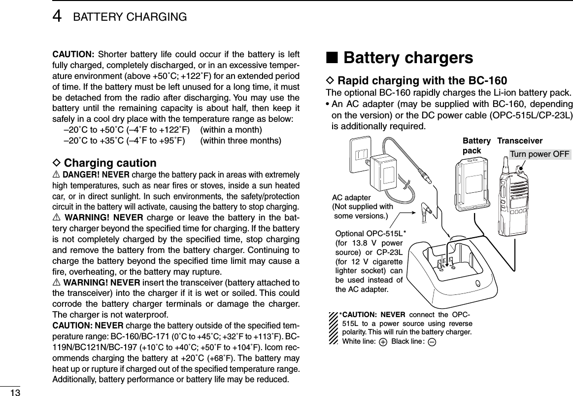
![206SPEAKER MICROPHONE12345678910111213141516Optional HM-168LWP description ■Alligator type clipTo attach the speaker-mic.to your shirt or collar, etc.PTT switchTransmits while pushedReceives while releasedMicrophoneSpeakerTurn the transceiver power OFF when connecting the HM-168LWP.NEVER immerse the connector in water. If the connector becomes wet, be sure to dry it BEFORE attaching it to the transceiver.NOTE: The microphone is located as shown in the dia-gram above. To maximize the readability of your transmit-ted signal (voice), hold the microphone approximately 5 to 10 cm (2 to 4 inches) from your mouth, and speak in a normal voice level.Attaching ■Attach the connector of the speaker-microphone into the [SP MIC] jack on the transceiver and tighten the screws with your fingers.NOTE: Use only your fingers instead of tools to tighten the screws. Hand tightenCAUTION: Attach the con-nector snugly.A loose connection will al-low water intrusion into the connector.IMPORTANT: Keep the [SP MIC] jack cover attached to the transceiver when the speaker-microphone is not in use.](https://usermanual.wiki/ICOM-orporated/352100.User-Manual/User-Guide-2128342-Page-25.png)