ICOM orporated 352201 UHF Transeiver User Manual
ICOM Incorporated UHF Transeiver
Contents
- 1. User Manual
- 2. Manual_Cut Antenna
User Manual
INSTRUCTION MANUAL
This device complies with Part 15 of the FCC Rules. Opera-
tion is subject to the condition that this device does not cause
harmful interference.
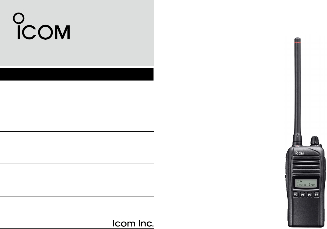
iF3230D Series
VHF TRANSCEIVERS
iF4230D Series
UHF TRANSCEIVERS
The photo shows the VHF
transceiver (S type)

i
IMPORTANT
READ ALL INSTRUCTIONS carefully and com-
pletely before using the transceiver.
SAVE THIS INSTRUCTION MANUAL — This
instruction manual contains important oper ating instructions
for the IC-F3230DT, IC-F3230DS VHF TRANSCEIVERS and
the IC-F4230DT, IC-F4230DS UHF TRANSCEIVERS.
See the operating guide for details of IDAS (ICOM Digital
Advanced System) system operations. Ask your dealer for
details.
EXPLICIT DEFINITIONS
WORD DEFINITION
RDANGER! Personal death, serious injury or an ex-
plosion may occur.
RWARNING! Personal injury, fire hazard or electric
shock may occur.
CAUTION Equipment damage may occur.
NOTE If disregarded, inconvenience only. No risk
of personal injury, fire or electric shock.
Icom, Icom Inc. and the Icom logo are registered trademarks of Icom Incor-
porated (Japan) in Japan, the United States, the United Kingdom, Germany,
France, Spain, Russia and/or other countries.

ii
R DANGER! NEVER short the terminals of the bat-
tery pack.
R DANGER! Use and charge only specified Icom bat-
tery packs with Icom radios or Icom chargers. Only Icom bat-
tery packs are tested and approved for use with Icom radios
or charged with Icom chargers. Using third-party or coun-
terfeit battery packs or chargers may cause smoke, fire, or
cause the battery to burst.
R WARNING! NEVER hold the transceiver so that
the antenna is very close to, or touching exposed parts of
the body, especially the face or eyes, while transmitting. The
transceiver will perform best if the microphone is 5 to 10 cm (2
to 4 inches) away from the lips and the transceiver is vertical.
R WARNING! NEVER operate the transceiver with
a headset or other audio accessories at high volume levels.
Hearing experts advise against continuous high volume op-
eration. If you experience a ringing in your ears, reduce the
volume level or discontinue use.
R WARNING! NEVER operate the transceiver while
driving a vehicle. Safe driving requires your full attention—
anything less may result in an accident.
CAUTION: MAKE SURE the flexible antenna, bat-
tery pack and jack cover are securely attached to the trans-
ceiver, and that the antenna and battery pack are dry before
attachment. Exposing the inside of the transceiver to dust or
water will result in serious damage to the transceiver.
DO NOT operate the transceiver near unshielded electri-
cal blast ing caps or in an explosive atmosphere.
DO NOT push [PTT] when not actually intending to transmit.
DO NOT use or place the transceiver in direct sunlight or
in areas with temperatures below –30°C (–22°F) or above
+60°C (+140°F).
The basic operations, transmission and reception of the trans-
ceiver are guaranteed within the specified operating tempera-
ture range. However, the LCD display may not be operate
correctly, or show an indication in the case of long hours of
operation, or after being placed in extremely cold areas.
DO NOT modify the transceiver. The transceiver warranty
does not cover any problems caused by unauthorized modi-
fication.
DO NOT use harsh solvents such as benzine or alcohol
when cleaning, as they will damage the transceiver surfaces.
BE CAREFUL! The transceiver will become hot when
operating it continuously for long periods of time.
PRECAUTIONS

iii
FCC INFORMATION
• FOR CLASS A UNINTENTIONAL RADIATORS:
This equipment has been tested and found to comply with the
limits for a Class A digital device, pursuant to part 15 of the
FCC Rules. These limits are designed to provide reasonable
protection against harmful interference when the equipment
is operated in a commercial environment. This equipment
generates, uses and can radiate radio frequency energy and,
if not installed and used in accordance with the instruction
manual, may cause harmful interference to radio communi-
cations. Operation of this equipment in a residential area is
likely to cause harmful interference in which case the user will
be required to correct the interference at his own expense.
CAUTION: Changes or modifications to this transceiver, not
expressly approved by Icom Inc., could void your authority to
operate this transceiver under FCC regulations.
PRECAUTIONS (Continued)
BE CAREFUL! The transceiver meet IP67* require-
ments for dust-tight and waterproof protection. However, once
the transceiver has been dropped, dust-tight and waterproof
protection cannot be guaranteed because of possible dam-
age to the transceiver’s case or the waterproof seal.
* Only when the jack cover or the optional HM-168LWP is
attached.
Even when the transceiver power is OFF, a slight current still
flows in the circuits. Remove the battery pack or batteries from
the trans ceiver when not using it for a long time. Otherwise,
the installed battery pack or batteries will become exhausted,
and will need to be recharged or replaced.
MAKE SURE to turn the transceiver power OFF before
connect ing the supplied/optional equipment.

iv
1
2
3
4
5
6
7
8
9
10
11
12
13
14
15
16
TABLE OF CONTENTS
IMPORTANT ..........................................................................i
EXPLICIT DEFINITIONS ....................................................... i
PRECAUTIONS .................................................................... ii
FCC INFORMATION ........................................................... iii
TABLE OF CONTENTS ....................................................... iv
1 ACCESSORIES ...........................................................1–2
Supplied accessories ■ ...................................................1
Accessory attachments ■ ................................................1
2 PANEL DESCRIPTION ................................................3–7
Front panel ■ ...................................................................3
Function display ■ ...........................................................4
Programmable function keys ■ ........................................5
3 BASIC OPERATION ..................................................8–11
Turning power ON ■ ........................................................8
Channel selection ■ ........................................................9
Receiving and transmitting ■ .........................................10
User set mode ■ ............................................................11
Priority A channel selection ■ ........................................11
4 BATTERY CHARGING ............................................12–16
Caution ■ .......................................................................12
Battery chargers ■ .........................................................13
5 BATTERY CASE ......................................................17–19
BP-240 optional battery case ■ .....................................17
BP-261 optional battery case ■ .....................................18
6 SPEAKER MICROPHONE ............................................20
Optional HM-168LWP description ■ ..............................20
Attaching ■ ....................................................................20
7 OPTIONAL SWIVEL BELT CLIP ............................21–22
MB-93 contents ■ ..........................................................21
Attaching ■ ....................................................................21
Detaching ■ ...................................................................22
8 OPTIONS .................................................................23–24
9 SAFETY TRAINING INFORMATION .......................25–26
1
1ACCESSORIES
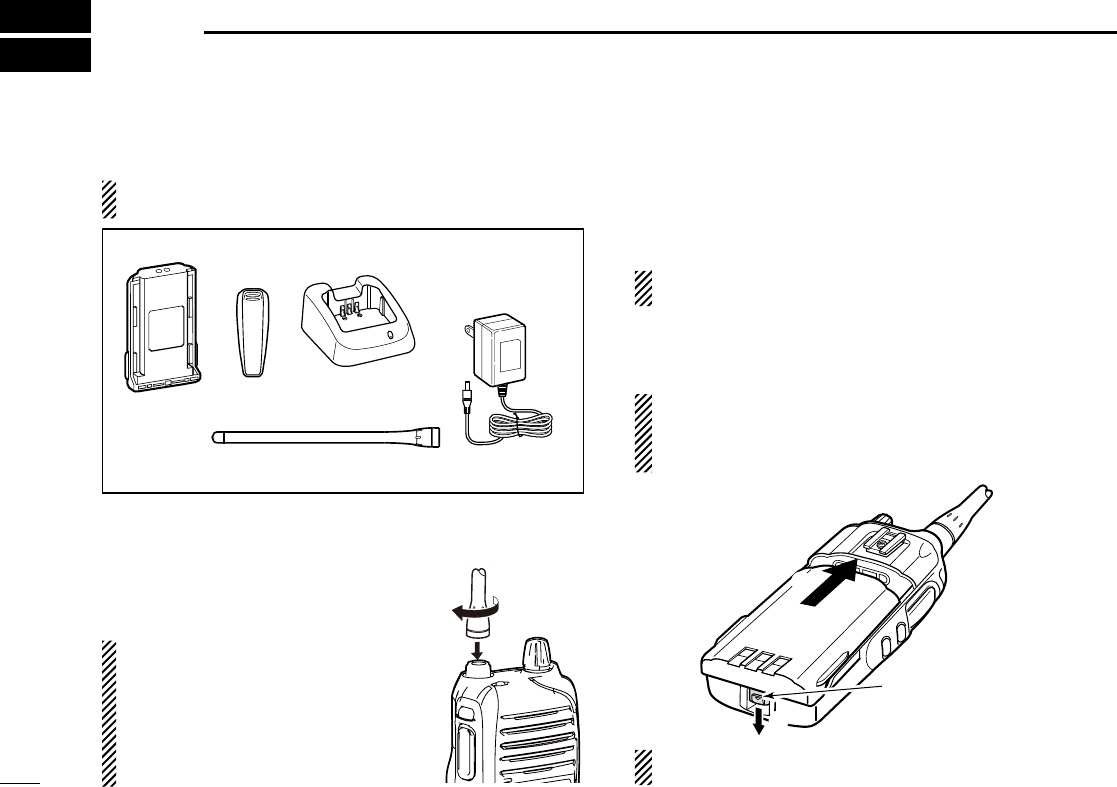
Supplied accessories ■
NOTE: Some accessories are not supplied, depending on
the transceiver version.
Flexible antenna*
(This illustration is of the VHF type.)
Battery pack
Belt clip AC adapter*
(for the battery charger)
Battery charger*
*Not supplied, or the shape is different, depending on the trans-
ceiver version.
Accessory attachments ■
Flexible antenna D
Connect the supplied flexible antenna to
the antenna connector.
CAUTION:
• NEVER carry the transceiver by
holding only the antenna.
• DO NOT connect an antenna other
than those listed on page 24.
• Transmitting without an antenna may
damage the transceiver.
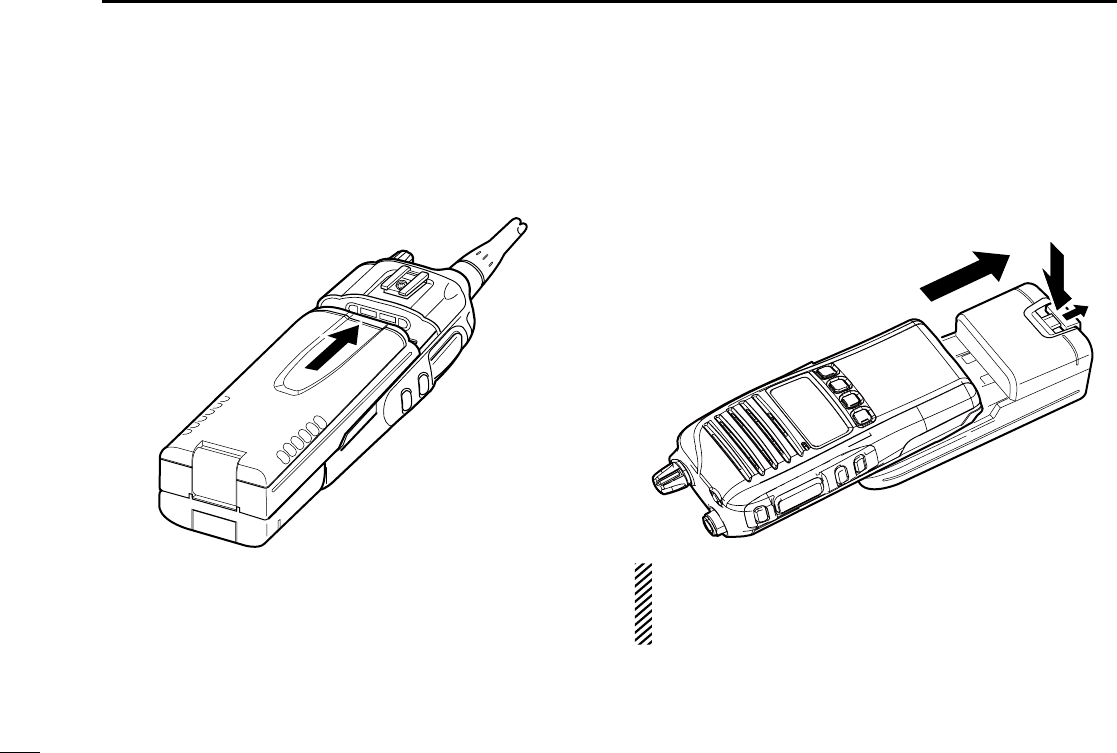
Battery pack D
To attach the battery pack:
Slide the battery pack in the direction of the arrow (q) until
the battery release button makes a ‘click’ sound.
NOTE: Push on the bottom of the pack to make sure the
release button is firmly locked.
To release the battery pack:
Slide the battery release button in the direction of the arrow
(w) as shown below. The battery pack is then released.
NEVER release or attach the battery pack when the trans-
ceiver is wet or soiled. This may result water or dust getting
into the transceiver/battery pack and may result in the
transceiver being damaged.
q
w
Battery release button
NOTE: Keep battery terminals clean. It’s a good idea to
occasionally clean them.
2
1
ACCESSORIES
1
2
3
4
5
6
7
8
9
10
11
12
13
14
15
16
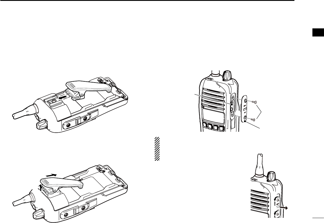
Belt clip D
To attach the belt clip:
Remove the battery pack if it is attached. q
w Slide the belt clip in the direction of the arrow until the belt
clip is locked and makes a ‘click’ sound.
To detach the belt clip:
Remove the battery pack if it is attached. q
Pinch the clip ( wq), and slide the belt clip in the direction of
the arrow (w).
q
w
Jack cover D
To attach the jack cover:
Attach the jack cover to the [MIC/SP] jack. ( qq)
Tighten the screws. ( ww)
w
[MIC/SP] jack
Jack cover
q
CAUTION:
• Attach the jack cover when the optional equipment is not
used.
• Use only the supplied screws.
To detach the jack cover:
Unscrew the screws using a phillips q
screwdriver. (q)
Detach the jack cover to connect the w
optional equipment. (w)
q
qw
3
2PANEL DESCRIPTION
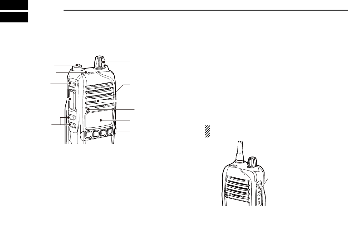
Front panel ■
q
w
r
e
o
u
y
Microphone
Speaker
t
i
q ANTENNA CONNECTOR
Connects the supplied antenna.
w DEALER-PROGRAMMABLE KEY [Emer]
A desired function can be programmed by your dealer. (p. 5)
e DEALER-PROGRAMMABLE KEY [Side1]
A desired function can be programmed by your dealer. (p. 5)
r PTT SWITCH [PTT]
Hold down to transmit, release to receive.
t DEALER-PROGRAMMABLE KEYS [Side2]/[Side3]
Desired functions can be independently programmed by
your dealer.
(p. 5)
y DEALER-PROGRAMMABLE KEYS [P0] to [P3]
Desired functions can be independently programmed by
your dealer.
(p. 5)
u FUNCTION DISPLAY
(p. 4)
Displays a variety of information such as an operating
channel number, channel name, User Set mode contents,
and so on.
i EXTERNAL MICROPHONE/SPEAKER JACK
Connect an optional equipment.
NOTE: Connect or disconnect the optional equipment
after the transceiver is turned OFF.
Jack cover
NOTE: Attach the jack
cover when optional
equipment is not used.
See (p. 2) for details.
o VOLUME CONTROL [VOL]
Rotate to turn the power ON or OFF and to adjust the au-
dio level.
4
2
PANEL DESCRIPTION
1
2
3
4
5
6
7
8
9
10
11
12
13
14
15
16
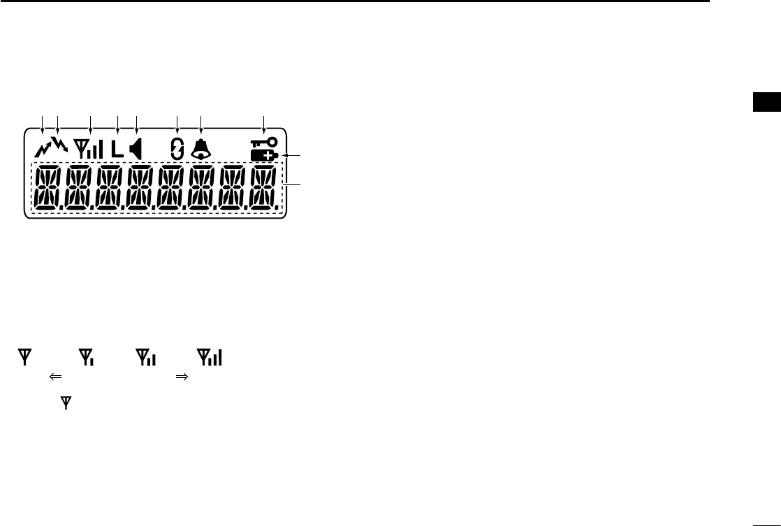
Function display ■
yq iutrew
o
!0
q TRANSMIT ICON
Appears while transmitting.
w BUSY ICON
Appears while the channel is busy (receiving).
e SIGNAL STRENGTH ICON
Shows the relative receive signal strength level.
Weak Receive Signal level Strong
About “ ” icon for the Trunking mode
Disappears while in a no service area. ➥
Blinks while registering to a repeater. ➥
Appears when registration is completed. ➥
r LOW POWER ICON
Appears when low output power is selected.
• When the battery power decreases to a specied level,
low power is automatically selected.
t AUDIBLE ICON
In the analog mode, appears when the CTCSS (DTCS) ➥
squelch mute is released while holding down [Monitor].
In the digital mode, appears while holding down [Moni- ➥
tor].
y ENCRYPTION ICON
In the digital mode, appears when the encryption function
is activated.
u BELL ICON
In the digital mode, appears/blinks when an SDM (Short
Data Message), Status Call or Call Alert is received, de-
pending on the preprogramming.
i KEY LOCK ICON
Appears when the Key lock function is ON.
o BATTERY ICON
Appears or blinks when the battery power decreases to a
specified level.
!0 ALPHANUMERIC DISPLAY
Displays an operating channel number, channel name,
User Set mode contents, and so on.

5
2PANEL DESCRIPTION
Programmable function keys ■
The following functions can be assigned to [Emer], [Side1],
[Side2], [Side3], [P0], [P1], [P2] and [P3] programmable
function keys.
Consult your Icom dealer or system operator for details con-
cerning your transceiver’s programming.
CH UP AND DOWN
As described in the following topics, after pushing a pro-
grammed key, push [CH Up] or [CH Down] to select an op-
tion, setting, and so on.
ZONE
Push this key, then select the desired zone using [CH Up]/
[CH Down].
What is a “zone”?— Certain channels are grouped to-
gether and assigned to a zone, according to their intended
use. For example, ‘Staff A’ and ‘Staff B’ are assigned to a
“Business” zone, and ‘John’ and ‘Cindy’ are assigned to a
“Private” zone.
SCAN START/STOP
Push to start and cancel a scan. ➥
• When a scan is started with the Power ON Scan or Automatic
scan function, push this key to cancel it. The cancelled scan re-
sumes after a preprogrammed time period.
➥ Hold down this key for 1 second to display the scan group,
then push [CH Up] or [CH Down] to select the desired
group.
SCAN ADD/DEL (TAG)
Push to add the channel to, or delete it from, the current ➥
scan group.
1. Push to display the scan group, then push [CH Up] or [CH Down]
to select the desired one.
2. Push to add the channel to, or delete it from, the selected scan
group.
3. Hold down for 1 second to exit the scan list selection mode.
While a scan is paused on a non-priority channel, push this ➥
key to delete the selected channel from the scan group.
Depending on the setting, the cleared channel may be
automatically added to the scan group again after the
scan is cancelled.

6
2
PANEL DESCRIPTION
2
PRIORITY A CHANNEL, PRIORITY B CHANNEL
Push to select the Priority A or Priority B channel.
PRIORITY A CHANNEL (REWRITE),
PRIORITY B CHANNEL (REWRITE)
Push to select the Priority A or Priority B channel. ➥
Hold down [Prio A (Rewrite)] or [Prio B (Rewrite)] for ➥
1 second to assign the operating channel to Priority A or
Priority B channel, respectively.
MEMORY CHANNELS 1, 2, 3, 4
Push to directly select memory channel 1, 2, 3 or 4, if pro-
grammed.
Consult your dealer for details.
MONITOR
Push to turn the CTCSS (DTCS) squelch mute ON or OFF.
LIGHT
Push to turn ON the backlight for about 5 seconds, when the
backlight function is set to “OFF” in the User Set mode.
LOCK
Hold down this key until “LOCK ON” is displayed to elec- ➥
tronically lock all programmable keys except the following:
[Moni], [Lock], [Emergency]*, [Surveillance], [Siren], [Lone
Worker]*, [Light] and [Shift].
* For digital operation. See the operating guide for details
To turn OFF the Key Lock function, hold down this key until ➥
“LOCK OFF” is displayed.
HIGH/LOW
Push to select the transmit output power temporarily or per-
manently, depending on the preprogramming.
• Ask your dealer for the output power level for each selection.
TALK AROUND
Push to turn the Talk Around function ON or OFF.
• The Talk Around function equalizes the transmit frequency to the
receive frequency for transceiver-to-transceiver communication.
WIDE/NARROW
Push to toggle the IF bandwidth between wide and narrow.
SURVEILLANCE
Push to turn the surveillance function ON or OFF.
When this function is turned ON and a signal is received, the
beep is not heard and the LED does not light, even if a key
is pushed.

7
2PANEL DESCRIPTION
Programmable function keys (Continued) ■
SIREN
Hold down for 1 second to sound the siren.
This function can be used for situations other than an emer-
gency alert, such as a security alarm for example.
• The siren can be stopped only by turning OFF the transceiver power.
USER SET MODE
Hold down for 1 second to enter the User Set mode. ➥
• While in the User Set mode, push this key to select an item*, and
change the value or setting by pushing [CH Up] or [CH Down].
* Selectable items may differ, depending on the preprogram-
ming.
Hold down this key for 1 second again to exit the User Set ➥
mode.
ANNOUNCE
Push to turn the Channel Announce function ON or OFF.
When this function is turned ON, the transceiver announces
the channel number when it is selected.
RESET
Push to return to the normal operating mode. ➥
While in the audible mode, push to return to the inaudible ➥
mode.
NOTE: See the operating guide for the [Reset] key opera-
tion in the digital mode.
SHIFT
Push to toggle the Normal mode key functions and the Shift
mode key functions.
• When the Shift mode is selected, the display briey shows “SHIFT
ON.” When the Normal mode is selected, the display briefly shows
“SHIFT OFF.”
8
3
BASIC OPERATION
1
2
3
4
5
6
7
8
9
10
11
12
13
14
15
16
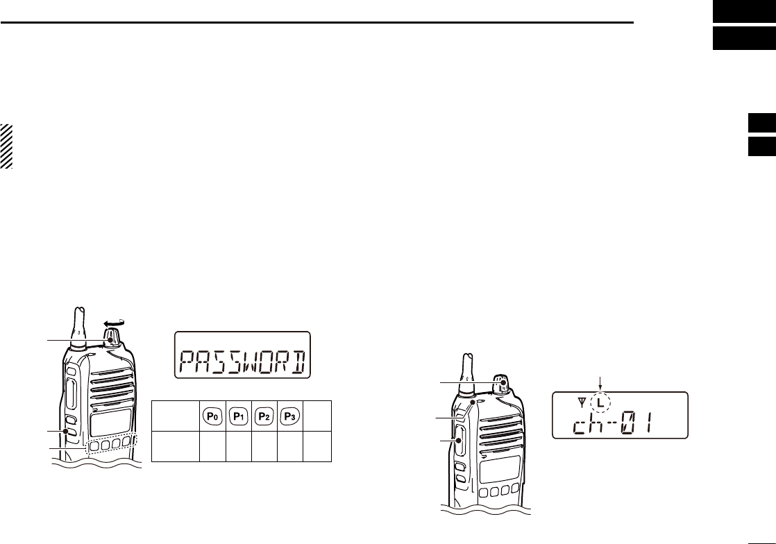
Turning power ON ■
Prior to using the transceiver for the first time, the battery
pack must be fully charged for optimum life and operation.
(p. 12)
Rotate [VOL] to turn ON the power. q
w If the transceiver is programmed for a start up password,
input the digit codes as directed by your dealer.
• The 10-keypad may be used for password input, depending on
the transceiver’s version:
• The keys in the table below can be used for password input.
• The transceiver detects numbers in the same block as identical.
Therefore “01234” and “56789” are the same.
KEY
NUMBER 0
5
4
9
3
8
2
7
1
6
[Side3]
[P0]/[P1]/
[P2]/[P3]
Side3
[VOL]
e When the “PASSWORD” indication does not clear after in-
putting 4 digits, the input code number may be incorrect.
Turn the power off and start over in this case.
Battery type selection D
The battery type must be selected according to the attached
battery type when turning ON the transceiver.
Ask your dealer for details.
Turn OFF the power. q
While pushing and holding [Emer] and [PTT], turn ON w
the power by rotating [VOL] to toggle the attached battery
type.
• After the display appears, release [Emer] and [PTT].
• “DRY BATT” is displayed for about 3 seconds then “L” appears
when the battery case use is selected. In this case, the transmit
output power is low.
• “LI-ION” is displayed for about 3 seconds when the Lithium-ion
battery use is selected.
[VOL]
[PTT]
[Emer]
Dry battery mode
Appears

9
3BASIC OPERATION
Channel selection ■
Several types of channel selections are available. Methods
may differ, depending on your system set up.
NON-ZONE TYPE:
To select the desired operating channel:
Push [CH Up] or [CH Down]. ➥
Push one of [MR-CH 1] to [MR-CH 4]. ➥
Push one of these keys, [Prio A], [Prio B], [Prio A (Re- ➥
write)] or [Prio B (Rewrite)].
ZONE TYPE:
To select the desired operating channel:
Push [Zone], then push [CH Up] or [CH Down]. ➥
VOTING OPERATION:
The transceiver automatically starts scanning when a zone,
specified for the voting operation, is selected.
The voting scan detects the S-meter of the repeater and au-
tomatically selects the strongest station.
AUTOMATIC SCAN TYPE:
Channel setting is not necessary for this type. When turning
ON the power, the transceiver automatically starts scanning.
Scanning stops when a signal is received.
NOTE: If the Move to Priority A channel at Power ON func-
tion is turned ON, the transceiver selects the Priority A
channel at Power ON, and then starts scanning. (p. 11)

10
3
BASIC OPERATION
3
Receiving and transmitting ■
CAUTION: Transmitting without an antenna may damage
the transceiver. See page 1 for accessory attachments.
Receiving:
Rotate [VOL] to turn ON the power. q
Push [CH Up] or [CH Down] to sequentially select the con- w
ventional system channel.
e When receiving a call, adjust the audio output level to a
comfortable listening level.
Transmitting:
Wait for the channel to become clear to avoid interference.
While pushing and holding [PTT], speak into the micro- q
phone at a normal voice level.
Release [PTT] to return to receive. w
IMPORTANT: To maximize the readability of your signal;
1. Pause briefly after pushing [PTT].
2. Hold the microphone 5 to 10 cm (2 to 4 inches) from
your mouth, then speak at a normal voice level.
Transmitting notes D
• Transmit inhibit function
The transceiver has several inhibit functions which restrict
transmission under the following conditions:
- The channel is busy. However, depending on the pre-
programmed settings, you can transmit when the call
includes an unmatching (or matching) CTCSS (DTCS),
RAN code*, or Individual or Talkgroup ID*.
* Digital operation only
- The selected channel is a ‘receive only’ channel.
• Time-out timer
If continuous transmission exceeds the preprogrammed
time-out timer limit, the transmission is cut off.
• Penalty timer
After the transmission is cut off by the time-out timer, trans-
mission is further inhibited for the preprogrammed penalty
timer period.

11
3BASIC OPERATION
User set mode ■
The User Set mode allows you to set seldom-changed set-
tings. If the transceiver has [User Set Mode] assigned to it,
you can “customize” the transceiver operation to suit your
preferences and operating style.
Entering the User Set mode:
Hold down [User Set Mode] for 1 second to enter the User q
Set mode.
Push [User Set Mode] several times to select the appro- w
priate item. Then push [CH Up] or [CH Down] to set the
desired level or condition.
• Selectable Set mode items are Backlight, Beep ON/OFF, Beep
Level, Ringer Level, SQL Level, AF Min Level, Mic Gain, Battery
Voltage, Signal Moni, Lone Worker and System Info.
Hold down [User Set Mode] for 1 second again to exit the e
User Set mode.
Priority A channel selection ■
When one of the following operations is performed, the trans-
ceiver automatically selects Priority A channel.
• Turning ON the power
Priority A channel is selected each time the transceiver’s
power is turned ON.
• Auto Reset
Priority A channel is selected when the Auto Reset timer
ends.
• OFF hook
Priority A channel is selected when you take the micro-
phone OFF hook.

12
4
BATTERY CHARGING
1
2
3
4
5
6
7
8
9
10
11
12
13
14
15
16
Caution ■
Misuse of Lithium-ion batteries may result in the following
hazards: smoke, fire, or the battery may rupture. Misuse
can also cause damage to the battery or degradation of
battery performance.
R DANGER! Use and charge only specified Icom battery packs
with Icom radios or Icom charger. Only Icom battery packs are
tested and approved for use and charge with Icom radios or Icom
charger. Using third-party or counterfeit battery packs or charger
may cause smoke, fire, or cause the battery to burst.
Battery caution D
R DANGER! DO NOT hammer or otherwise impact the battery.
Do not use the battery if it has been severely impacted or dropped,
or if the battery has been subjected to heavy pressure. Battery
damage may not be visible on the outside of the case. Even if the
surface of the battery does not show cracks or any other damage,
the cells inside the battery may rupture or catch fire.
R DANGER! NEVER use or leave battery packs in areas with
temperatures above +60˚C (+140˚F). High temperature buildup
in the battery, such as could occur near fires or stoves, inside
a sun heated car, or in direct sunlight may cause the battery to
rupture or catch fire. Excessive temperatures may also degrade
battery performance or shorten battery life.
R DANGER! DO NOT expose the battery to rain, snow, seawa-
ter, or any other liquids. Never charge or use a wet battery. If the
battery gets wet, be sure to wipe it dry before using.
R DANGER! NEVER incinerate used battery packs since inter-
nal battery gas may cause them to rupture, or may cause an
explosion.
R DANGER! NEVER solder the battery terminals or NEVER
modify the battery pack. This may cause heat generation, and
the battery may rupture, emit smoke or catch fire.
R DANGER! Use the battery only with the transceiver for which
it is specified. Never use a battery with any other equipment, or
for any purpose that is not specified in this instruction manual.
R DANGER! If fluid from inside the battery gets in your eyes,
blindness can result. Rinse your eyes with clean water, without
rubbing them, and see a doctor immediately.
R WARNING! Immediately stop using the battery if it emits an
abnormal odor, heats up, or is discolored or deformed. If any of
these conditions occur, contact your Icom dealer or distributor.
R WARNING! Immediately wash, using clean water, any part
of the body that comes into contact with fluid from inside the
battery.
R WARNING! NEVER put the battery in a microwave oven, high-
pressure container, or in an induction heating cooker. This could
cause a fire, overheating, or cause the battery to rupture.
CAUTION: Always use the battery within the specified tempera-
ture range, –20˚C to +60˚C (–4˚F to +140˚F). Using the battery
out of its specified temperature range will reduce the battery’s
performance and battery life.
13
4BATTERY CHARGING
CAUTION: Shorter battery life could occur if the battery is left
fully charged, completely discharged, or in an excessive temper-
ature environment (above +50˚C; +122˚F) for an extended period
of time. If the battery must be left unused for a long time, it must
be detached from the radio after discharging. You may use the
battery until the remaining capacity is about half, then keep it
safely in a cool dry place with the temperature range as below:
–20˚C to +50˚C (–4˚F to +122˚F) (within a month)
–20˚C to +35˚C (–4˚F to +95˚F) (within three months)
Charging caution D
R DANGER! NEVER charge the battery pack in areas with extremely
high temperatures, such as near fires or stoves, inside a sun heated
car, or in direct sunlight. In such environments, the safety/protection
circuit in the battery will activate, causing the battery to stop charging.
R WARNING! NEVER charge or leave the battery in the bat-
tery charger beyond the specified time for charging. If the battery
is not completely charged by the specified time, stop charging
and remove the battery from the battery charger. Continuing to
charge the battery beyond the specified time limit may cause a
fire, overheating, or the battery may rupture.
R WARNING! NEVER insert the transceiver (battery attached to
the transceiver) into the charger if it is wet or soiled. This could
corrode the battery charger terminals or damage the charger.
The charger is not waterproof.
CAUTION: NEVER charge the battery outside of the specified tem-
perature range: BC-160/BC-171 (0˚C to +45˚C; +32˚F to +113˚F). BC-
119N/BC121N/BC-197 (+10˚C to +40˚C; +50˚F to +104˚F). Icom rec-
ommends charging the battery at +20˚C (+68˚F). The battery may
heat up or rupture if charged out of the specified temperature range.
Additionally, battery performance or battery life may be reduced.
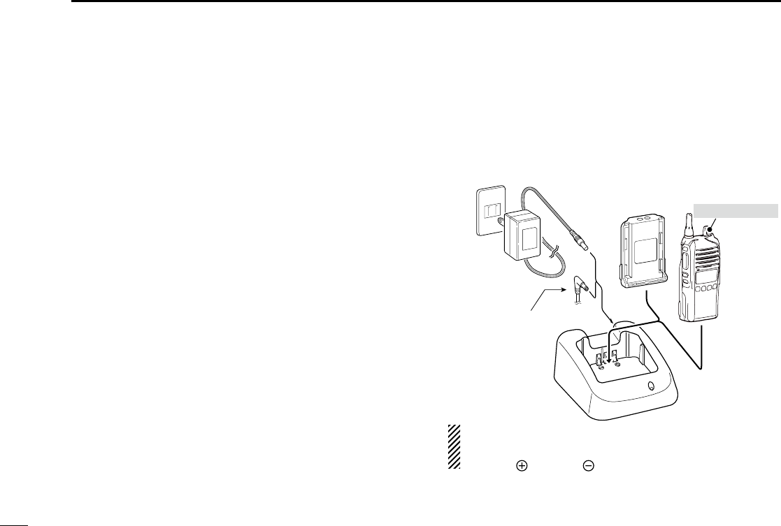
Battery chargers ■
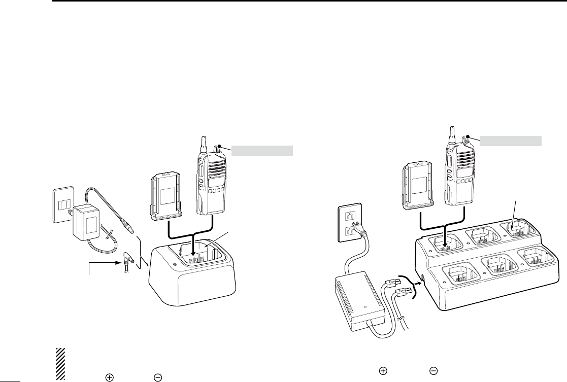
Rapid charging with the BC-160 D
The optional BC-160 rapidly charges the Li-ion battery pack.
• An AC adapter (may be supplied with BC-160, depending
on the version) or the DC power cable (OPC-515L/CP-23L)
is additionally required.
AC adapter
(Not supplied with
some versions.)
Optional OPC-515L
(for 13.8 V power
source) or CP-23L
(for 12 V cigarette
lighter socket) can
be used instead of
the AC adapter.
*
TransceiverBattery
pack Tu rn power OFF
CAUTION: NEVER connect the OPC-
515L to a power source using reverse
polarity. This will ruin the battery charger.
White line: Black line :
*
14
4
BATTERY CHARGING
1
2
3
4
5
6
7
8
9
10
11
12
13
14
15
16
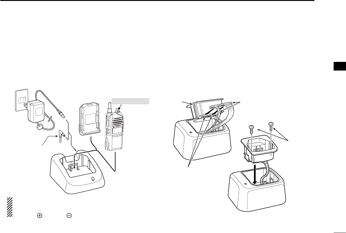
Regular charging with the BC-171 D
The optional BC-171 regularly charges the Li-ion battery
pack.
• An AC adapter (may be supplied with BC-171, depending
on the version) or the DC power cable (OPC-515L/CP-23L)
is additionally required.
AC adapter
(Not supplied with
some versions.)
Optional OPC-515L
(for 13.8 V power
source) or CP-23L
(for 12 V cigarette
lighter socket) can
be used instead of
the AC adapter.
*
TransceiverBattery
pack Tu rn power OFF
CAUTION: NEVER connect the OPC-
515L to a power source using reverse
polarity. This will ruin the battery charger.
White line: Black line :
*
AD-106 installation D
The AD-106 c h a r g e r a d a p t e r must be installed into the BC-
119N or BC-121N before battery charging.
Connect the AD-106 ➥c h a r g e r a d a p t e r and the BC-119N/
BC-121N as ahown below, then install the AD-106 into the
holder space of the BC-119N or BC-121N with the sup-
plied screws.
Screws supplied
with the charger
adapter
AD-106 Connectors
Plugs
* This illustration is of the BC-119N.
15
4BATTERY CHARGING
Rapid charging with the BC-119N+AD-106 D
The optional BC-119N rapidly charges the Li-ion battery pack.
The following items are additionally required.
• AD-106 charger adapter
• An AC adapter (may be supplied with the BC-119N, de-
pending on the version) or the DC power cable (OPC-515L/
CP-23L).
AD-106 charger
adapter is installed
in BC-119N.
AC adapter
(Not supplied with
some versions.)
Optional OPC-515L
(for 13.8 V power
source) or CP-23L
(for 12 V cigarette
lighter socket) can
be used instead of
the AC adapter.
Transceiver
Battery
pack
Tu rn power OFF
CAUTION: NEVER connect the OPC-
515L to a power source using reverse
polarity. This will ruin the battery charger.
White line: Black line :
*
*
Rapid charging with the BC-121N+AD-106 D
The optional BC-121N can simultaneously charge up to 6
Li-ion battery packs. The following items are additionally re-
quired.
• Six AD-106 charger adapters
•
An optional AC adapter or the DC power cable (OPC-656)
Battery
pack
AD-106 charger
adapters are installed
in each slot.
AC adapter
(Purchased
separately)
Transceiver
DC power cable (OPC-656)
(Connect with the DC power supply; 13.8 V/at least 7 A)
*Abou the OPC-656
Red line : Black line :
Tu rn power OFF
16
4
BATTERY CHARGING
1
2
3
4
5
6
7
8
9
10
11
12
13
14
15
16
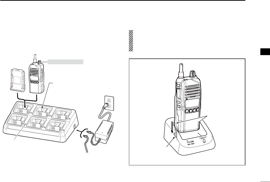
Rapid charging with the BC-197 D
The optional BC-197 can simultaneously charge up to 6 Li-ion
battery packs. The following items are additionally required.
•
An optional AC adapter
(not supplied with some versions)
or
the DC power cable (OPC-656)
Transceiver
Battery pack Tu rn OFF the power
Status indicator
(each indicator independently functions)
OPC-656 (DC power cable)
AC adapter
(No AC adapt-
er is supplied,
depending on
the version.)
(Connect to a DC power supply;
12 to 16 V/at least 7 A)
Red line : + Black line : _
IMPORTANT: Battery charging caution
Ensure the guide tabs on the battery pack are correctly
aligned with the guide rails inside the charger adapter.
(This illustration is of the BC-160.)
Guide rail
Tabs
The charger adapters are in-
stalled in each slot. The shape
of charger adapter depends
on the version of the BC-197.
17
5BATTERY CASE
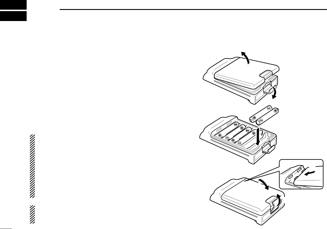
BP-240 optional battery case ■
When using the BP-240 battery case, install six AAA (LR03)
size alkaline batteries, as illustrated to the right. The BP-240
is constructed to the IPX4 waterproof standard.
Unhook the battery cover release hook ( qq), and open the
cover in the direction of the arrow (w). (Fig.1)
Install six AAA (LR03) size alkaline batteries. (Fig.2) w
• Install only alkaline batteries.
• Be sure to observe the correct polarity.
Replace the cover in the direction of the arrow ( ee), then
close (r). Push the battery cover release hook until it
makes a ‘click’ sound (t). (Fig.3)
CAUTION:
• When installing the batteries, make sure they are all the
same brand, type and capacity. Also, do not mix new and
old batteries together.
• Keep battery terminals clean. It’s a good idea to occa-
sionally clean them.
• Never incinerate used battery cells since internal battery
gas may cause them to rupture.
•
Never expose a detached battery case to water. If the bat-
tery case gets wet, be sure to wipe it dry before using it.
NOTE: When the optional battery case is attached, the
battery type must be set to “DRY BATT” when turning ON
the transceiver. (p. 8)
q
BP-240
w
Fig.1
Fig.2
Fig.3
e
r
t
18
5
BATTERY CASE
1
2
3
4
5
6
7
8
9
10
11
12
13
14
15
16
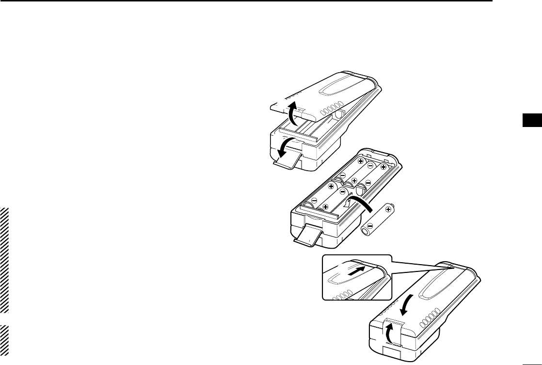
BP-261 optional battery case ■
Alkaline batteries installation D
Install six AA (LR6) size alkaline batteries as described below.
The BP-261 is constructed to the IPX4 waterproof standard.
Unhook the battery cover release hook ( qq), and open the
cover in the direction of the arrow (w). (Fig.1)
Install six AA (LR6) size alkaline batteries. (Fig.2) w
• Install only alkaline batteries.
• Be sure to observe the correct polarity.
Replace the cover in the direction of the arrow ( ee), then
close (r). Push the battery cover release hook until it
makes a ‘click’ sound (t). (Fig.3)
CAUTION:
• When installing the batteries, make sure they are all the
same brand, type and capacity. Also, do not mix new and
old batteries together.
• Keep battery terminals clean. It’s a good idea to occa-
sionally clean them.
• Never incinerate used battery cells since internal battery
gas may cause them to rupture.
•
Never expose a detached battery case to water. If the bat-
tery case gets wet, be sure to wipe it dry before using it.
NOTE: When the optional battery case is attached, the
battery type must be set to “DRY BATT” when turning ON
the transceiver. (p. 8)
BP-261
Fig.1
Fig.2
Fig.3
t
r
e
q
w
19
5BATTERY CASE
BP-261 optional battery case (Continued) ■
Attaching D
Slide the battery pack in the direction of the arrow until the
battery release button makes a ‘click’ sound.
Detaching D
Slide the battery case’s battery release button in the direction
of the arrow (q), and then push the release button in the di-
rection of the arrow (w). The battery pack is then released.
q
w
NEVER release or attach the battery case when the trans-
ceiver is wet or soiled. This may result water or dust getting
into the transceiver or battery case and may result in the
transceiver being damaged.
20
6
SPEAKER MICROPHONE
1
2
3
4
5
6
7
8
9
10
11
12
13
14
15
16
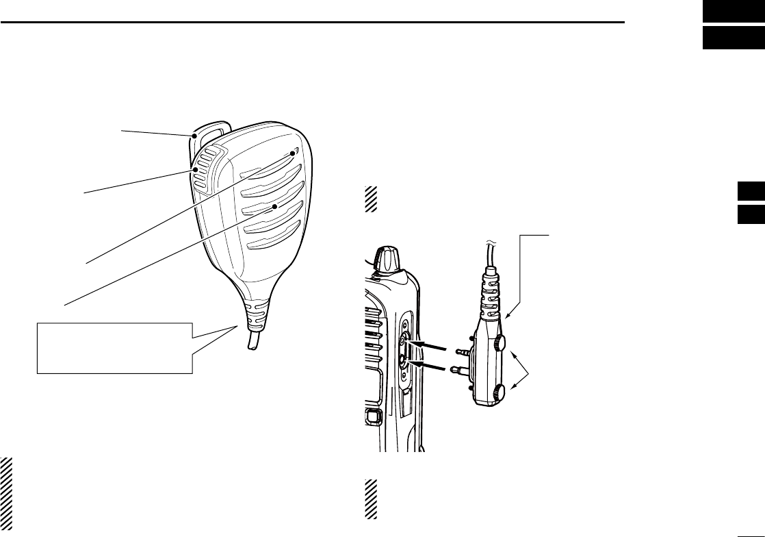
Optional HM-168LWP description ■
Alligator type clip
To attach the speaker-mic.
to your shirt or collar, etc.
PTT switch
Transmits while pushed
Receives while released
Microphone
Speaker
Turn the transceiver power
OFF when connecting the
HM-168LWP.
NEVER immerse the connector in water. If the connector
becomes wet, be sure to dry it BEFORE attaching it to the
transceiver.
NOTE: The microphone is located as shown in the dia-
gram above. To maximize the readability of your transmit-
ted signal (voice), hold the microphone approximately 5 to
10 cm (2 to 4 inches) from your mouth, and speak in a
normal voice level.
Attaching ■
Attach the connector of the speaker-microphone into the [SP
MIC] jack on the transceiver and tighten the screws with your
fingers.
NOTE: Use only your fingers instead of tools to tighten the
screws.
Hand tighten
CAUTION: Attach the con-
nector snugly.
A loose connection will al-
low water intrusion into the
connector.
IMPORTANT: Keep the [SP MIC] jack cover attached to
the transceiver when the speaker-microphone is not in
use.
21
7OPTIONAL SWIVEL BELT CLIP
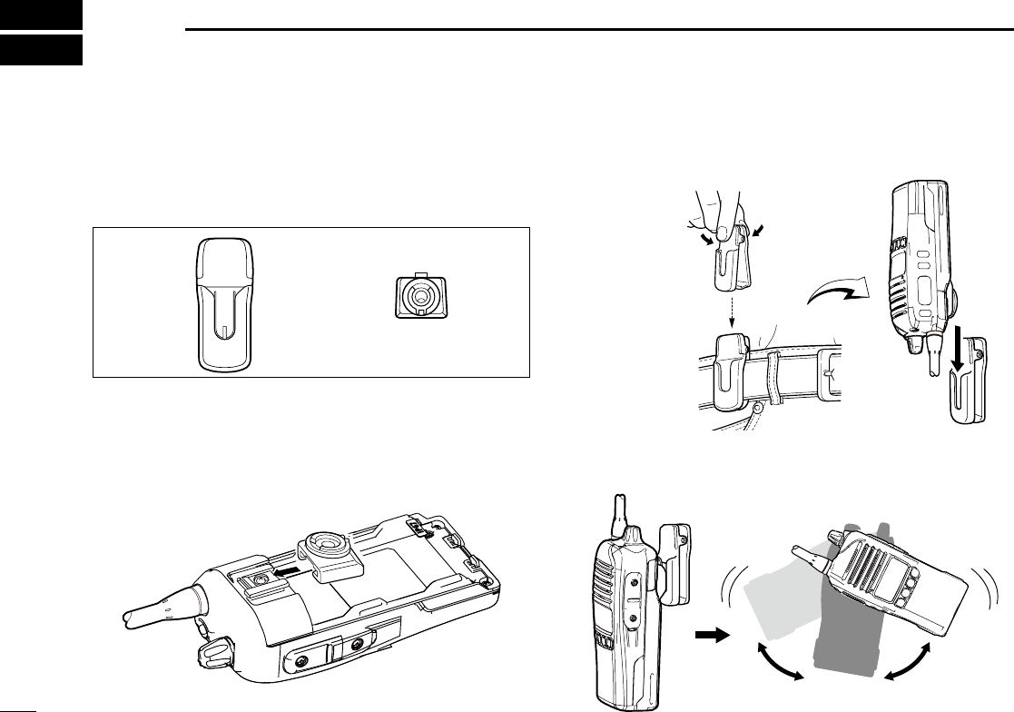
MB-93 contents ■
Qty.
q Belt clip ...........................................................................1
w Base clip .........................................................................1
q w
Attaching ■
Release the battery pack if it is attached. (p. 1) q
w Slide the base clip in the direction of the arrow until the
base clip locks and makes a ‘click’ sound.
Attach the battery pack. (p. 1) e
Clip the belt clip to a part of your belt. And insert the trans- r
ceiver into the belt clip until the base clip inserted fully into
the groove.
Once the transceiver is locked in place, it swivels as illus- t
trated below.
Once the transceiver is locked in place,
it will swivel 360 degrees.
22
7
OPTIONAL SWIVEL BELT CLIP
1
2
3
4
5
6
7
8
9
10
11
12
13
14
15
16
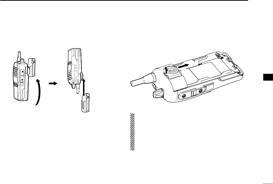
Detaching ■
q Turn the transceiver upside down in the direction of the
arrow and pull it out of the belt clip.
Release the battery pack if it is attached. (p. 1) w
e Pinch the clip (q), and slide the base clip in the direction
of the arrow (w).
q
w
CAUTION:
HOLD THE TRANSCEIVER TIGHTLY, WHEN HANGING
OR DETACHING THE TRANSCEIVER FROM THE BELT
CLIP.
Otherwise the transceiver may not be attached to the
holder or swivel properly if the transceiver is accidentally
dropped and the base clip is scratched or damaged.

23
8OPTIONS
BATTERY PACK D
Battery pack Voltage Capacity Battery life*
BP-232WP 7.4 V 2250 mAh (min.)
2300 mAh (typ.) 20 hrs.
*
When the power save function is turned ON, and the operating peri-
ods are calculated under the following conditions;
TX : RX : standby = 5 : 5 : 90
• BP-240/BP-261 b at t e r y c a s e
BP-240: Battery case for 6 AAA (LR03) alkaline batteries
BP-261: Battery case for 6 AA (LR6) alkaline batteries
BP-240 and BP-261 have IPX4 waterproof protection. When
in use, the transceiver’s waterproof rating meets IPX4.
Operating period depends on the alkaline cells used.
CHARGERS D
• BC-119N d e s k t o p c h a r g e r + AD-106 c h a r g e r a d a p t e r
+ BC-145S a c a d a p t e r
For rapid charging of battery packs. An AC adapter may
supplied with the charger, depending on the versions.
Charging time: Approximately 3 hours for the BP-232WP.
• BC-121N m u l t i -c h a r g e r + AD-106 c h a r g e r a d a p t e r (6 pcs.)
+ BC-157S a c a d a p t e r
For rapid charging of up to 6 battery packs (six AD-106’s
are required) simultaneously. An AC adapter should be pur-
chased separately.
Charging time: Approximately 3 hours for the BP-232WP.
• BC-160 d e s k t o p c h a r g e r + BC-145S a c a d a p t e r
For rapid charging of battery packs. An AC adapter may be
supplied with the charger, depending on the versions.
Charging time: Approximately 3 hours for the BP-232WP.
• BC-171 d e s k t o p c h a r g e r + BC-147S a c a d a p t e r
An AC adapter may supplied with the charger, depending on
the versions.
Charging time: Approximately 10 hours for the BC-232WP.
• BC-197 m u l t i -c h a r g e r
For rapid
simultaneously
charging of up to six battery packs
.
An AC adapter may
be supplied with the charger, depending
on the version.
Charging time: Approximately 3 hours for the BP-232WP.
DC CABLES D
• CP-23L c i g a r e t t e l i g h t e r c a b l e
Allows charging of the battery pack through a 12 V cigarette
lighter socket. (For BC-160/BC-171/BC-119N)
• OPC-515L/OPC-656 d c p o w e r c a b l e s
Allows charging of the battery pack using a 13.8 V power
source instead of the AC adapter.
OPC-515L: For BC-119N/BC-160/BC-171
OPC-656: For BC-121N/BC-197
BELT CLIPS D
• MB-93 s w i v e l b e lt c l i p
• MB-94/94R b e lt c l i p
Exclusive alligator-type belt clip.
• MB-96N/96F l e at h e r b e lt h a n g e r

24
8
OPTIONS
1
2
3
4
5
6
7
8
9
10
11
12
13
14
15
16
OTHER OPTIONS D
• HM-158LA/HM-159LA/
HM-168LWP
s p e a k e r -m i c r o p h o n e
Combination speaker-microphone that provides convenient
operation while hanging the transceiver on your belt.
• HM-153LA/HM-166LA e a r p h o n e -m i c r o p h o n e
Ideal for hands-free operation: clip the HM-153LA/HM-
166LA (with integrated PTT switch) to your lapel or breast
pocket.
Allows you to operate in rainy conditions.
• FA-SC25V/FA-SC55V/FA-SC25U/
FA-SC57U/FA-SC72U/FA-SC62V/
FA-SC63V/FA-SC03U a n t e n n a s
FA-SC25V: 136–150 MHz FA-SC55V: 150–174 MHz
FA-SC25U: 400–430 MHz FA-SC57U: 430–470 MHz
FA-SC72U: 470–520 MHz FA-SC62V: 150–160 MHz
FA-SC63V: 155–165 MHz FA-SC03U: 380–430 MHz
• FA-SC56VS/FA-SC57VS/FA-SC73US s t u b b y a n t e n n a s
FA-SC56VS: 150–162 MHz FA-SC57VS: 160–174 MHz
FA-SC73US: 450–490 MHz
• FA-SC61VC/FA-SC61UC c u t a n t e n n a s
FA-SC61VC: 136–174 MHz FA-SC61UC: 380–520 MHz
• MB-130 v e h i c l e c h a r g e r b r a c k e t
Mounts the BC-160 d e s k t o p c h a r g e r onto variety of plac-
es in a vehicle.
Some options may not be available in some countries. Ask
your dealer for details.
Approved Icom optional equipment is designed for optimal
performance when used with an Icom transceiver.
Icom is not responsible for the destruction or damage to an
Icom transceiver in the event the Icom transceiver is used with
equipment that is not manufactured or approved by Icom.

25
9SAFETY TRAINING INFORMATION
WARNING
Y
our Icom radio generates RF electromagnetic ener-
gy during transmit mode. This radio is designed for
and classified as “Occupational Use Only”, meaning it
must be used only during the course of employment
by individuals aware of the hazards, and the ways to
minimize such hazards. This radio is NOT intended for
use by the “General Population” in an uncontrolled environment.
This radio has been tested and complies with the FCC and IC RF
exposure limits for “Occupational Use Only”. In addition, your Icom
radio complies with the following Standards and Guidelines with re-
gard to RF energy and electromagnetic energy levels and evaluation
of such levels for exposure to humans:
• FCC OET Bulletin 65 Edition 97-01 Supplement C, Evaluating
Compliance with FCC Guidelines for Human Exposure to Radio
Frequency Electromagnetic Fields.
• American National Standards Institute (C95.1-1992), IEEE
Standard for Safety Levels with Respect to Human Exposure to
Radio Frequency Electromagnetic Fields, 3 kHz to 300 GHz.
• American National Standards Institute (C95.3-1992), IEEE Rec-
ommended Practice for the Measurement of Potentially Hazard-
ous Electromagnetic Fields– RF and Microwave.
• The following accessories are authorized for use with this prod-
uct. Use of accessories other than those specified may result
in RF exposure levels exceeding the FCC and IC requirements
for wireless RF exposure.; Belt Clip (MB-93, MB-94/R and MB-
96N/F), Rechargeable Li-ion Battery Pack (BP-232WP) and
Speaker-microphone (HM-158LA/HM-159LA/HM-168LWP).
CAUTION
To ensure that your expose to RF electromagnetic
energy is within the FCC and IC allowable limits
for occupational use, always adhere to the follow-
ing guidelines:
• DO NOT operate the radio without a proper antenna attached, as
this may damaged the radio and may also cause you to exceed
FCC and IC RF exposure limits. A proper antenna is the antenna
supplied with this radio by the manufacturer or antenna specifi-
cally authorized by the manufacturer for use with this radio.
•
DO NOT transmit for more than 50% of total radio use time (“50%
duty cycle”). Transmitting more than 50% of the time can cause
FCC and IC
RF exposure compliance requirements to be exceed-
ed. The radio is transmitting when the TX indicator lights red. You
can cause the radio to transmit by pressing the “PTT” switch.
• ALWAYS keep the antenna at least 2.5 cm (1 inch) away from
the body when transmitting and only use the Icom belt-clips
listed on page 23 when attaching the radio to your belt, etc., to
ensure FCC and IC RF exposure compliance requirements are
not exceeded. To provide the recipients of your transmission the
best sound quality, hold the antenna at least 5 cm (2 inches)
from your mouth, and slightly off to one side.
The information listed above provides the user with the information
needed to make him or her aware of RF exposure, and what to do
to assure that this radio operates with the FCC and IC RF exposure
limits of this radio.
Electromagnetic Interference/Compatibility
During transmissions, your Icom radio generates RF energy that can
possibly cause interference with other devices or systems. To avoid such
interference, turn off the radio in areas where signs are posted to do so.
DO NOT operate the transmitter in areas that are sensitive to electro-
magnetic radiation such as hospitals, aircraft, and blasting sites.
Occupational/Controlled Use
The radio transmitter is used in situations in which persons are ex-
posed as consequence of their employment provided those persons
are fully aware of the potential for exposure and can exercise control
over their exposure.

26
9
SAFETY TRAINING INFORMATION
1
2
3
4
5
6
7
8
9
10
11
12
13
14
15
16
Votre radio Icom produit une énergie électromagnétique
de radiofréquences (RF), en mode de transmission.
Cette radio est conçue pour un «usage professionnel
seulement» et classée comme tel, ce qui signifie qu’elle
doit être utilisée uniquement dans le cadre d'un travail
par des personnes conscientes des dangers et des me-
sures visant à minimiser ces dangers. Elle N’EST PAS conçue pour une
«utilisation grand public», dans un environnement non contrôlé.
Cet appareil a été évalué et jugé conforme, aux limites d
’
exposition aux
RF de la FCC et d’IC, pour une «utilisation grand public». En outre, votre
radio Icom satisfait les normes et directives qui suivent en matière de
niveaux d'énergie et d
’
énergie électromagnétique de RF et d
’
évaluation
de tels niveaux en ce qui concerne l
’
exposition humaine:
• Supplément C, édition 97-01, du Bulletin OET n° 65 de la FCC,
«Evaluating Compliance with FCC Guidelines for Human Exposure
to Radio Frequency Electromagnetic Fields».
• Norme de l’American National Standards Institute (ANSI): IEEE
C95.1-1992 sur les niveaux de sécurité compatibles avec l
’
exposition
humaine aux champs électromagnétiques de radiofréquences (3 kHz
à 300 GHz).
• Norme de l’ANSI: IEEE C95.3-1992 sur la méthode d’évaluation re-
commandée du champ magnétique potentiellement dangereux des
radiofréquences et des micro-ondes.
•
Les accessoires illustrés à la p. 23-24 sont approuvés pour une utilisa-
tion avec ce produit. L’utilisation d’accessoires autres que ceux précisés
peut entraîner des niveaux d’exposition aux RF supérieures aux limites
établies par la FCC et d’IC en matière d’exposition aux RF sans fil.
Afin de vous assurer que votre exposition à
une énergie électromagnétique de RF se situe
dans les limites permises par la FCC et d’IC
pour une utilisation grand public, veuillez en
tout temps respecter les directives suivantes:
•
NE PAS faire fonctionner la radio sans qu
’
une antenne appropriée y soit
fixée, car ceci risque d
’
endommager la radio et causer une exposition
supérieure aux limites établies par la
FCC et d’IC
. L
’
antenne appropriée
est celle qui est fournie avec cette radio par le fabricant ou une antenne
spécialement autorisée par le fabricant pour être utilisée avec cette radio.
• NE PAS émettre pendant plus de 50 % du temps total d’utilisation de
l’appareil («50 % du facteur d'utilisation»). La notion «50% du facteur
d’utilisation» s’applique également au mode VOX/PTT. Émettre pen-
dant plus de 50 % du temps total d’utilisation peut causer une exposi-
tion aux RF supérieure aux limites établies par la
FCC et d’IC
. Lorsque
le voyant DEL rouge s’allume, cette radio est en train d’émettre. La
radio émettra si vous appuyez sur le bouton du microphone.
• TOUJOURS tenir l
’
antenne éloignée d
’
au moins 2,5 cm de votre corps
au moment d
’
émettre et utiliser uniquement l
’
attache pour ceinture Icom
illustrée à la p. 23, lorsque vous attachez la radio à votre ceinture, ou à
autre chose, de façon à vous assurer de ne pas provoquer une exposi-
tion aux RF supérieure aux limites fixées par la
FCC et d’IC
. Pour offrir
à vos interlocuteurs la meilleure qualité de transmission possible, tenez
l
’
antenne à au moins 5 cm de votre bouche et légèrement de côté.
Les renseignements ci-dessus fournissent à l’utilisateur toute l’information
nécessaire sur l’exposition aux RF et sur ce qu’il faut faire pour assurer que
cette radio fonctionne en respectant les limites d’exposition aux RF établies
par la
FCC et d’IC
.
Interférence électromagnétique et compatibilité
En mode de transmission, votre radio Icom produit de l’énergie de RF qui
peut provoquer des interférences avec d’autres appareils ou systèmes. Pour
éviter de telles interférences, mettez la radio hors tension dans les secteurs
où une signalisation l’exige. NE PAS faire fonctionner l’émetteur dans des
secteurs sensibles au rayonnement électromagnétique tels que les hôpi-
taux, les aéronefs et les sites de dynamitage.
Usage professionnel/contrôlé
Ce radio émetteur est utilisé dans des cas où des personnes sont exposées
en raison de leur travail, pourvu qu’elles soient conscientes du risque d’ex-
position et qu’elles puissent exercer un contrôle sur cette exposition.

1-1-32 Kamiminami, Hirano-ku, Osaka 547-0003, Japan
A-7082D-1EX-0a
Printed in Japan
© 2013 Icom Inc.
Printed on recycled paper with soy ink.