ICOM orporated 362102 UHF Transceiver User Manual 3
ICOM Incorporated UHF Transceiver 3
UserManual.wiki
>
ICOM orporated
>
362102 User Manual
>
User Manual 3
Contents
1.
User Manual 1
2.
User Manual 2
3.
User Manual 3
4.
User Manual 4
User Manual 3
Navigation menu
Upload a User Manual
Namespaces
Wiki Guide
HTML
PDF
Info
Views
User Manual
Discussion / Help
Navigation
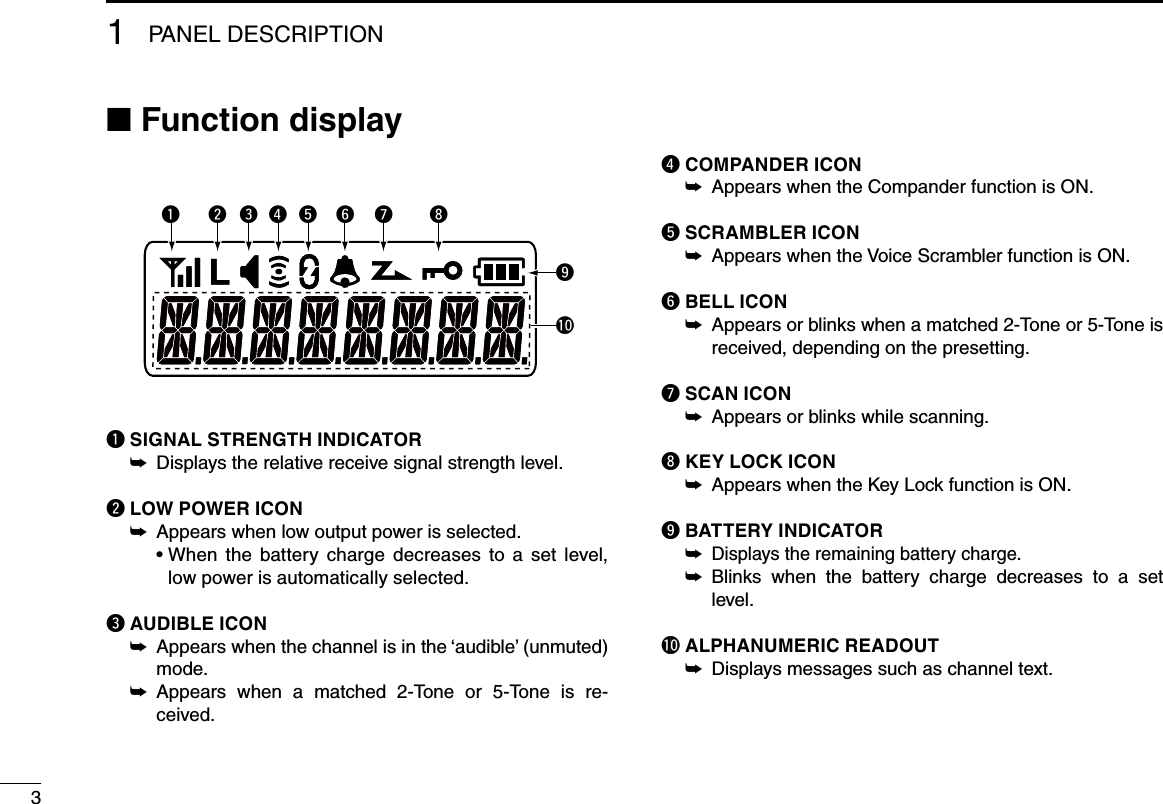
![■ Front, top and side panels* Names for the non-display type transceiverThere are three types of transceivers in the IC-F1000 and IC-F2000 series.IC-F1000/F2000: Non-display typeIC-F1000S/F2000S: Simple type [display + 4 keys (P0–P3)]IC-F1000T/F2000T: 10-key type [display + 4 keys + 10-key pad]The illustration is for the 10-key type.Your transceiver may have a FUNCTION DISPLAY, [P0]–[P3], or 10-KEY PAD, depending on the transceiver version.q ROTARY SELECTOR Rotate to select the preset memory channels. ➥w VOLUME CONTROL [VOL] Rotate to turn the power ON or OFF and to adjust the ➥audio level.e DEALER-ASSIGNABLE KEY [Emer]A desired function can be programmed by your dealer. ➥11PANEL DESCRIPTIONw VOLUME CONTROL [VOL]e [Emer]Speakerr SPEAKER- MICROPHONE JACKMicrophonet FUNCTION DISPLAYy [P0], [P1], [P2], [P3]10-KEY PADi PTT SWITCH [PTT]o LED INDICATOR!0 ANTENNA CONNECTORu [UP]/ [Upper]*u [DOWN]/ [Lower]*q ROTARY SELECTOR](https://usermanual.wiki/ICOM-orporated/362102.User-Manual-3/User-Guide-2467499-Page-4.png)
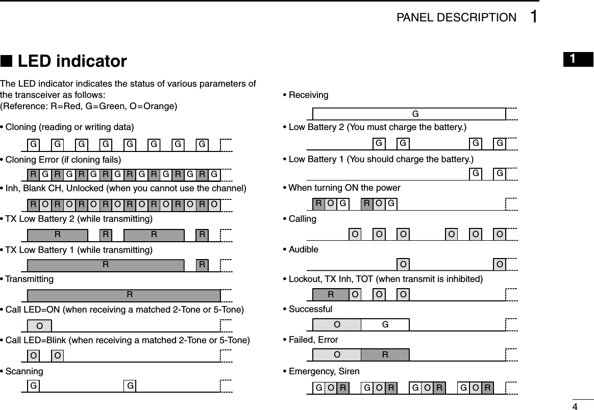
![21PANEL DESCRIPTION12345678910111213141516r SPEAKER-MICROPHONE JACKConnect optional equipment. ➥NOTE: After turning OFF the transceiver, connect or dis-connect the optional equipment.t FUNCTION DISPLAY Displays a variety of information such as the operating ➥channel number, channel name, User Set mode con-tents, and so on. See page 3 for details.y DEALER-ASSIGNABLE KEYS [P0]–[P3] Desired functions can be independently programmed ➥by your dealer.u DEALER-ASSIGNABLE KEYS [UP] or [Upper]*, [DOWN] or [Lower]* Desired functions can be independently programmed ➥by your dealer. * Names for the non-display type transceiversi PTT SWITCH [PTT]Hold down to transmit, release to receive. ➥o LED INDICATORLights red while transmitting. ➥ Lights green while receiving a signal, or when the ➥squelch is open. Lights or blinks orange when the matched 2-Tone or ➥5-Tone is received, depending on the presetting. You should charge the battery when the indicator slow- ➥ly blinks. You must charge the battery when the indicator blinks ➥fast.!0 ANTENNA CONNECTORConnects the supplied antenna. ➥Jack coverNOTE: Attach the jack cover when optional equipment is not used.](https://usermanual.wiki/ICOM-orporated/362102.User-Manual-3/User-Guide-2467499-Page-5.png)
![51PANEL DESCRIPTION■ Programmable function keysFor the Non-display type transceivers, the following functions can be assigned to [Emer], [Upper], and [Lower].For the Simple type transceivers and the 10-key type trans-ceivers, the following functions can be assigned to [P0], [P1], [P2], [P3], [Emer], [Up], and [Down].Consult your Icom dealer or system operator for details con-cerning your transceiver’s programming.CH UP/DOWN As described in the following topics, after pushing a pro- ➥grammed key, push [CH Up] or [CH Down] to select an option, setting, and so on.ZONE // only for the Simple type and 10-key type transceivers // Push this key, then select the desired zone by pushing ➥[CH Up] or [CH Down]. What is a “zone”?— Certain channels are grouped to-gether and assigned to a zone, according to their intend-ed use. For example, ‘Staff A’ and ‘Staff B’ are assigned to a “Business” zone, and ‘John’ and ‘Cindy’ are assigned to a “Private” zone. SCAN START/STOP< for the Non-display type transceivers >Push to start and cancel a scan. ➥ • When a scan is started with the Power ON Scan or Auto-matic scan function, push this key to cancel it. The can-celled scan resumes after a set time period. < for the Simple type and 10-key type transceivers >Push to start and cancel a scan. ➥ ➥ To select the scan group, hold down this key to display scan groups, then push [CH Up] or [CH Down] to select a desired group.SCAN ADD/DEL (TAG)// only for the Simple type and 10-key type transceivers // Push to add the operating channel to, or delete it from, the ➥scan group. 1. Hold down to display the scan group, then push [CH Up] or [CH Down] to select the desired one. 2. Push to add the channel to, or delete it from, the select-ed scan group. 3. Hold down to exit the scan list selection mode. While a scan is paused on a non-priority channel, push this ➥key to delete the selected channel from the scan group. Depending on the presetting, the cleared channel may be automatically added to the scan group again after the scan is cancelled.](https://usermanual.wiki/ICOM-orporated/362102.User-Manual-3/User-Guide-2467499-Page-8.png)
![611PANEL DESCRIPTIONPRIORITY A CHANNEL, PRIORITY B CHANNELPush to select the Priority A or Priority B channel. ➥PRIORITY A CHANNEL (REWRITE),PRIORITY B CHANNEL (REWRITE)Push to select the Priority A or Priority B channel. ➥ Hold down ➥[Prio A (Rewrite)] or [Prio B (Rewrite)] to as-sign the operating channel to Priority A or Priority B chan-nel, respectively.MEMORY CHANNELS 1, 2, 3, 4 Push to directly select memory channel 1, 2, 3 or 4, if pro- ➥grammed.MONI // only for the LMR mode // Hold down to cancel the CTCSS (DTCS) or 2-Tone mute. ➥The transceiver enters “Audible” mode.Push to turn OFF the function. ➥MONI (Audi) // only for the PMR mode // Hold down to cancel the CTCSS (DTCS) or 5-Tone mute. ➥The transceiver enters “Audible” mode. Push or hold down to activate one or two functions if pro- ➥grammed.LOCK< for the Non-display type transceivers > Hold down this key to lock all programmable keys except ➥the followings: [Moni], [Lock], [Emer], [Surveillance], [Siren], [Lone Worker], and [Shift].< for the Simple type and 10-key type transceivers > Hold down until “LOCK ON” is displayed to lock all pro- ➥grammable keys except the followings: [ M o n i ] , [Lock], [Emer], [Surveillance], [Siren], [Lone Worker], and [Shift]. To turn OFF the Key Lock function, hold down until “LOCK ➥OFF” is displayed.LONE WORKER< for the Non-display type transceivers > Hold down to turn ON the Lone Worker Function. ➥Push to turn OFF the Function. ➥< for the Simple type and 10-key type transceivers >Push to turn the Lone Worker Function ON or OFF. ➥ • If no operation occurs for a set time period, the trans-ceiver automatically enters the emergency mode.HIGH/LOW Push to select the transmit output power temporarily or ➥permanently, depending on the presetting.](https://usermanual.wiki/ICOM-orporated/362102.User-Manual-3/User-Guide-2467499-Page-9.png)
![71PANEL DESCRIPTIONC.Tone CH ENT // only for the Simple type and 10-key type transceivers // Push to enter the continuous tone selection mode. Select ➥the tone frequency or DTCS code using [CH Up] or [CH Down].TALK AROUNDPush to turn the Talk Around function ON or OFF. ➥ • The Talk Around function equalizes the transmit frequen-cy to the receive frequency for transceiver-to-transceiver communication.WIDE/NARROW Push to toggle the channel passband width between wide ➥and narrow. DTMF AUTODIAL< for the Non-display type transceivers > Push to transmit the preprogrammed DTMF code. ➥< for the Simple type and 10-key type transceivers > Push to enter the DTMF number selection mode. Then se- ➥lect a DTMF number by pushing [CH Up] or [CH Down]. After selecting the DTMF channel, push again to transmit ➥the selected DTMF code.RE-DIALPush to transmit the last-transmitted DTMF code. ➥NOTE: TX memories are cleared after turning OFF the transceiver.CALL Push to transmit a 2-Tone or 5-Tone in the operating chan- ➥nel.CALL A (CODE 1)/CODE B (CODE 2)// only for the LMR model // Push to transmit a 2-Tone, that is programmed in channel ➥1 (Code A) or channel 2 (Code B).CALL A (CODE 30)/CODE B (CODE29)// only for the PMR model // Push to transmit a 5-Tone as a station code, that is pro- ➥grammed in channel 30 (Code A) or channel 29 (Code B).EMERGENCY Hold down during the Emer SW ON timer period to turn ➥ON the Emergency function. • After the Start or Repeat timer period ends, an Emer-gency call is automatically transmitted once, or repeat-edly, depending on the presetting. Hold down during the Emer SW OFF timer period to can- ➥cel the Emergency function, before transmitting an Emer-gency call.](https://usermanual.wiki/ICOM-orporated/362102.User-Manual-3/User-Guide-2467499-Page-10.png)
![811PANEL DESCRIPTIONSURVEILLANCE< for the Non-display type transceivers >Hold down to turn ON the Surveillance function. ➥Push to turn OFF the function. ➥< for the Simple type and 10-key type transceivers >Push to turn the Surveillance function ON or OFF. ➥ • When this function is ON and a signal is received, a beep does not sound and the LED does not light, even if you push any key.SIRENHold down to emit a siren sound. ➥ • This function may use for situations other than an emer-gency alert, such as a security alarm. Turning OFF the transceiver power to stop the siren ➥sound.TX CODE ENTER// only for the PMR model (for the Simple type and 10-key type transceivers) //Push to enter the TX code edit mode (5-Tone). ➥ 1. P u s h [CH Up] or [CH Down] to select the desired digit. You can also enter the digit using the 10-key pad, if it is on your transceiver. 2. Push [TX Code Enter] to set. The digit to the right will automatically blink. 3. Repeat step 1 and step 2 to input all editable digits. 4. After editing, push [TX Code Enter] to store the setting and return to the standby mode.TX CODE CH SELECT// only for the Simple type and 10-key type transceivers // Push ➥[TX Code CH Select] to enter the TX code channel selection mode. 1. Push [CH Up] or [CH Down] to select a desired TX code channel. 2. After selecting, push [TX Code CH Select] to store the setting and return to the standby mode.// only for the PMR model // During TX code selection mode, hold down to enter the TX ➥code edit mode (5-Tone). 1. P u s h [CH Up] or [CH Down] to select the desired digit. You can also enter the digit using the 10-key pad if it is on your transceiver. 2. Push [TX Code Enter] to set. The digit to the right will automatically blink. 3. Repeat step 1 and step 2 to input all editable digits. 4. After editing, push [TX Code Enter] to store the set-tings and return to the standby mode.TX CODE CH UP/DN// only for the LMR model (for the Simple type and 10-key type transceivers) //Push to select a preprogrammed TX code channel. ➥](https://usermanual.wiki/ICOM-orporated/362102.User-Manual-3/User-Guide-2467499-Page-11.png)
![91PANEL DESCRIPTIONTX CODE CH UP/DOWN// only for the PMR model (for the Simple type and 10-key type transceivers) //Push to select a preprogrammed TX code channel. ➥Push to select a desired digit in the TX code edit mode. ➥ID-MR SELECT// only for the PMR model (for the Simple type and 10-key type transceivers) //Push to recall the received ID code. ➥ • The transceiver can memorize up to 5 codes. Select a desired code by pushing ➥[CH Up] or [CH Down].Hold down to clear the selected ID code. ➥SCRAMBLER< for the Non-display type transceivers >Hold down to turn ON the Voice Scrambler function. ➥Push to turn OFF the function. ➥< for the Simple type and 10-key type transceivers >Push to turn the Voice Scrambler function ON or OFF. ➥COMPANDER< for the Non-display type transceivers >Hold down to turn ON the Compander function. ➥Push to turn OFF the function. ➥< for the Simple type and 10-key type transceivers >Push to turn the Compander function ON or OFF. ➥ • The Compander function reduces noise components from the transmitted audio to provide clear communication.USER SET MODE// only for the Simple type and 10-key type transceivers //Hold down to enter the User Set mode. ➥ • While in the User Set mode, push this key to select an item*, and change the value or setting by pushing [CH Up] or [CH Down]. * Selectable items may differ, depending on the presetting. Hold down this key again to exit the User Set mode. ➥ANNOUNCEPush to turn the Channel Announce function ON or OFF. ➥NOTE:When the Beep function (p.16) is OFF, the operating chan-nel is not announced, regardless of this setting. SHIFT// only for the Simple type and 10-key type transceivers // 1. Push to turn ON the Shift mode key functions. “SHIFT ON” is briefly displayed.2. Push another key to activate its secondary function.3. Push [Shift] again to turn OFF the function. The transceiver returns to the Normal mode, then “SHIFT OFF” is briefly displayed. • The Shift mode enables a programmable function key to have two functions at the same time.](https://usermanual.wiki/ICOM-orporated/362102.User-Manual-3/User-Guide-2467499-Page-12.png)
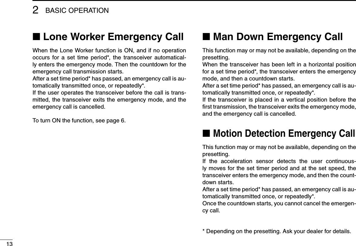
![1021615131411121098765431BASIC OPERATION 2■ Selecting a channelThere are several types of channel selections. Methods may differ, depending on the presetting. Consult your dealer for details.NON-ZONE TYPE:To select the desired operating channel:Rotate ➥[ROTARY SELECTOR].Push ➥[CH Up] or [CH Down].Push one of ➥[MR-CH 1] to [MR-CH 4]. Push ➥[Prio A], [Prio B], [Prio A (Rewrite)] or [Prio B (Re-write)].ZONE TYPE:To select the desired operating channel:Push ➥[Zone], then push [CH Up] or [CH Down].AUTOMATIC SCAN TYPE:Channel setting is not necessary for this scan type. When turning ON the power, the transceiver automatically starts scanning. Scanning stops when a signal is received.■ Receiving and transmittingCAUTION: Attach an antenna before transmitting. Transmitting without an antenna may damage the trans-ceiver. Receiving:Rotate q[VOL] to turn ON the power. Rotate w[ROTARY SELECTOR], or push one of the memo-ry channel keys, [MR-CH1] to [MR-CH4], to select a chan-nel. e When receiving a call, adjust the audio output level to a comfortable listening level.Transmitting:Wait until the channel is clear to avoid interference. While holding down q [PTT], speak at a normal voice level.Release w[PTT] to receive.IMPORTANT: To maximize the readability of your signal:1. After pushing [PTT], pause briefly before you start speaking.2. Hold the microphone 5 to 10 cm (2 to 4 inches) from your mouth, then speak at a normal voice level.](https://usermanual.wiki/ICOM-orporated/362102.User-Manual-3/User-Guide-2467499-Page-13.png)
![122BASIC OPERATION 2122■ Emergency CallWhen pushing [Emergency] for the set time period*, the transceiver transmits an emergency signal once, or repeat-edly, on the specified emergency channel.The transceiver automatically transmits a repeat emergen-cy signal until it receives an acknowledgement signal, or you turn OFF the transceiver power.When no emergency channel is specified, it transmits the signal on the previously selected channel.If you want to cancel the emergency call, hold down [Emer-gency] again before transmitting the call.If your transceiver is programmed for Silent operation, you can transmit an Emergency call without the beep sounding and the LED indicator lighting.IMPORTANT: It is recommended to set an emergency channel individually to provide the certain emergency call operation.NOTE:Depending on the presetting, the following functions are automatically activated. Ask your dealer for details.Auto TX function•After an emergency call transmission, the transceiver trans-mits the audio from the microphone for a set time period.*Auto RX function•After the emergency call transmission, the transceiver stands by in the audible mode for the set time period.** Depending on the presetting. Ask your dealer for details.](https://usermanual.wiki/ICOM-orporated/362102.User-Manual-3/User-Guide-2467499-Page-15.png)
![14216151413121110987654312BASIC OPERATION■ User set modeThe User Set mode enables you to change various settings. You can “customize” the transceiver operation to suit your preferences and operating style.The display illustration is for the Simple type and 10-key type transceivers.< for the Non-display type transceivers >For settings of the microphone gain, the squelch level, the Beep level, the Beep function, and the Ringer level, see page 16 to 19.< for the Simple type and 10-key type transceivers >When [User Set Mode] is assigned to your transceiver, see page 9 for entering the User Set mode.BacklightON: Always lit• AUT: Lit for 5 seconds when pushing • any key except [PTT].AU2: Lit for 5 seconds every time the • display changes the contents. OFF: Does not light• Beep ON/OFFON: Beeps sound• OFF: No beeps sound• Beep Level1 (minimum) – 5 (maximum)• 1• ❋ (minimum) – 5❋ (maximum) Linked with the audio level. The beep audio level is adjustable by rotating [VOL].Ringer Level1 (minimum) – 5 (maximum)• 1• ❋ (minimum) – 5❋ (maximum) Linked with the audio level. The ringer audio level is adjustable by rotating [VOL].](https://usermanual.wiki/ICOM-orporated/362102.User-Manual-3/User-Guide-2467499-Page-17.png)
![162BASIC OPERATION 21615141312111098765431■ Setting the Beep functionThese instructions are for the non-display type transceivers.The Beep function can be turned ON or OFF. When it is OFF, the channel announcement is also turned OFF.NOTE:You should turn ON the Beep function when you set the Beep level, the Ringer level, the microphone gain, and the squelch level.Rotate q[VOL] to turn the transceiver power OFF. Set w[ROTARY SELECTOR] to any channel other than Channel 16. While holding down e[Lower], rotate [VOL] to turn ON the power to enter the Beep level adjustment mode. P u s h r[Lower] to turn the Beep function ON or OFF. • When a beep sounds after pushing [Lower], the Beep function is ON. When no beep sounds after pushing [Lower], the Beep function is OFF. • The transceiver stores the setting every time you change it. • If desired, push [Upper] to adjust the Beep level. See page 17 for details. Rotate t[VOL] to turn OFF the power to exit the Beep level adjustment mode.[ROTARY SELECTOR][VOL][Lower][Upper]](https://usermanual.wiki/ICOM-orporated/362102.User-Manual-3/User-Guide-2467499-Page-19.png)
![17BASIC OPERATION2■ Setting the Beep levelThese instructions are for the non-display type transceivers.The Beep level is adjustable between 1 and 5, or 1 (linked) and 5 (linked). When a Linked option is selected, the beep audio level is adjustable by rotating [VOL].Rotate q[VOL] to turn OFF the transceiver. Set w[ROTARY SELECTOR] to any channel other than Channel 16. While holding down e[Lower], rotate [VOL] to turn ON the power and enter the Beep level adjustment mode. P u s h r[Upper] to change the Beep level. • Repeatedly pushing [Upper] first selects 1 (lowest) to 5 (highest), and then selects the lowest linked level, 1 (Linked) to the highest, 5 (Linked). Repeatedly pushing [Upper] repeats the cycle. See the illustration on the right. • The adjustable range is 1 to 5 or 1 (Linked) to 5 (Linked). • A beep sounds every time you push [Upper]. Therefore, you can determine the current level setting by the increasing loud-ness of the beep that sounds. • To determine if you have selected a linked level, set [VOL] to minimum, then push [Upper] repeatedly, listening for the loud-est beep (level 5). Pushing [Upper] once after the loudest beep will select 1 (Linked). Repeatedly push [Upper] to select the desired linked level. Rotate t[VOL] to turn OFF the power to exit the Beep level adjustment mode.NOTE:This operation may not be selectable, depending on the presetting, Ask your dealer for details.[ROTARY SELECTOR][VOL][Upper][Lower]254315 (Linked)4 (Linked)3 (Linked)2 (Linked)1 (Linked)Pushing[Upper]](https://usermanual.wiki/ICOM-orporated/362102.User-Manual-3/User-Guide-2467499-Page-20.png)
![1821615141312111098765431BASIC OPERATION 2■ Setting the Ringer levelThese instructions are for the non-display type transceivers.The Ringer level can be adjusted between 1 and 5, or 1 (Linked) and 5 (Linked). When a Linked option is selected, the ringer audio level is adjustable by rotating [VOL].Rotate q[VOL] to turn OFF the transceiver power.Set w[ROTARY SELECTOR] to Channel 16. While holding down e[Lower], rotate [VOL] to turn ON the power and enter the Ringer level adjustment mode. P u s h r[Upper] to increase, or push [Lower] to decrease the Ringer level. • Repeatedly pushing [Upper] first selects 1 (lowest) to 5 (highest), and then selects the lowest linked level, 1 (Linked) to the highest, 5 (Linked). Repeatedly pushing [Upper] or [Lower] repeats the cycle. See the illustration on the right. • The adjustable range is 1 to 5 or 1 (Linked) to 5 (Linked). • A beep sounds after pushing [Upper]. Therefore, you can determine the current level setting by the increasing loudness of the beep that sounds. • To determine if you have selected a linked level, set [VOL] to minimum, then push [Upper] up to 10 times, listening for the loudest beep (level 5). Pushing [Upper] once after the loudest beep will select 1 (Linked). Repeatedly push [Upper] or [Lower] to select the desired linked level. Rotate t[VOL] to turn OFF the power to exit the Ringer level adjustment mode.NOTE: This operation may not be selectable, depending on the presetting. Ask your dealer for details.254315 (Linked)4 (Linked)3 (Linked)2 (Linked)1 (Linked)Pushing[Lower]Pushing[Upper][ROTARY SELECTOR][VOL][Upper][Lower]](https://usermanual.wiki/ICOM-orporated/362102.User-Manual-3/User-Guide-2467499-Page-21.png)
![19BASIC OPERATION2■ Setting the microphone gainThese instructions are for the non-display type transceivers.Adjust the microphone gain.Rotate q[VOL] to turn the transceiver power OFF.Set w[ROTARY SELECTOR] to Channel 16. While holding down e[Upper], rotate [VOL] to turn ON the power and enter the microphone gain adjustment mode. P u s h r[Upper] or to increase, or push [Lower] to decrease the microphone gain. • The adjustable range is 1 (minimum) to 4 (maximum). • A beep sounds after pushing [Upper] or [Lower]. An error beep sounds if you try to exceed the adjustable range. Rotate t[VOL] to turn OFF the power to exit the microphone gain adjustment mode.NOTE: This operation may not be selectable, depending on the presetting. Ask your dealer for details.■ Setting the squelch levelThese instructions are for the non-display type transceivers.The squelch circuit mutes the received audio signal, de-pending on the signal strength.Rotate q[VOL] to turn the transceiver power OFF. Set w[ROTARY SELECTOR] to any channel other than Channel 16. While holding down e[Upper], rotate [VOL] to turn ON the power and enter the squelch level adjustment mode. P u s h r[Upper] to increase the squelch level (tight squelch), or push [Lower] to decrease the squelch level (loose squelch). • The adjustable range is 0 (loose squelch) to 9 (tight squelch). • A beep sounds after pushing [Upper] or [Lower]. An error beep sounds if you try to exceed the adjustable range. Rotate t[VOL] to turn OFF the power to exit the squelch level adjustment mode.NOTE: This operation may not be selectable, depending on the presetting. Ask your dealer for details.](https://usermanual.wiki/ICOM-orporated/362102.User-Manual-3/User-Guide-2467499-Page-22.png)
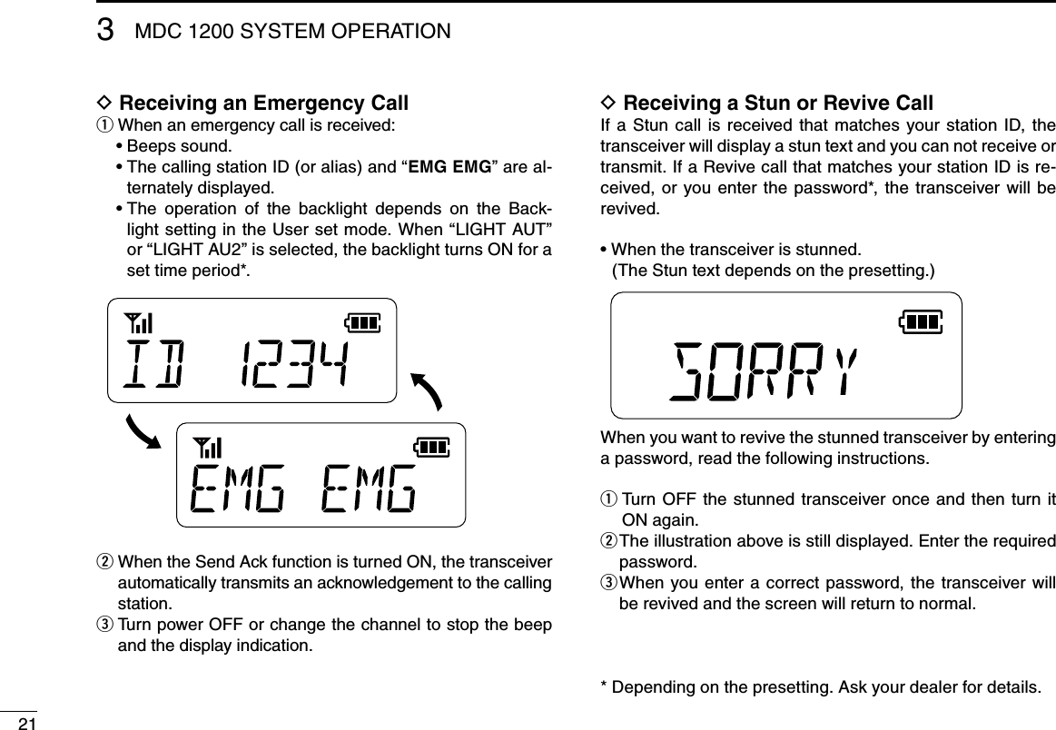
![20231615141312111098765413MDC 1200 SYSTEM OPERATION■ MDC 1200 system operationThe MDC 1200 signaling system enhances your transceiver’s capabilities. You can receive or transmit PTT ID and Emer-gency calls. You can also receive Radio Check, Stun, and Revive calls.An additional feature of the MDC 1200 system included in Icom transceivers is called aliasing. Each transceiver on the system has a unique ID number. Aliasing is a substitute for this ID number and you can give an alphanumeric name for each station ID. In transmit, you can use this alias to select a transceiver to call. In receive, the alias of the calling station is displayed instead of the ID.Please confirm that your dealer has set one of the program-mable keys for MDC 1200 system operation. See page 5 for more information about the programmable function keys.The display illustration is for the Simple type and 10-key type transceivers.■ Receiving a callReceiving a PTT ID D When a PTT ID is received: q Beeps sound.• The calling station ID (or alias) is displayed.• < Calling station ID >< Alias >w Hold down [PTT] and speak into the microphone.e Release [PTT] to receive a response.](https://usermanual.wiki/ICOM-orporated/362102.User-Manual-3/User-Guide-2467499-Page-23.png)
![2231615141312111098765421MDC 1200 SYSTEM OPERATION 3■ Transmitting a callTransmitting a PTT ID DYou can notify another person of your station ID or alias.Push q[PTT] to make a call.Beeps sound, depending on the presetting. w Your alias or station ID will be transmitted when you push e[PTT] (at the beginning of transmission) or release it (at the end of transmission), depending on the presetting.Transmitting an Emergency Call DWhen holding down [Emergency] for a set time period, the emergency signal is transmitted once or repeatedly* on the emergency channel. When no emergency channel is speci-fied, the signal is transmitted on the operating channel.* When the Repeat Cancel function is ON, the transceiver cancels repeating after receiving an acknowledgement. When the Repeat Cancel function is OFF, the transceiver repeats calling according to the number of repeat cycles, even after receiv-ing an acknowledgement.If you want to cancel the emergency call, hold down the key again before transmitting the call.You can transmit an emergency call without a beep emis-sion, and the display indication, depending on the preset-ting. (Silent operation)The transceiver can also be programmed to keep the micro-phone open during an emergency call, allowing monitoring the situation. Ask your dealer for details.IMPORTANT: It is recommended to set an emergency channel individually to provide the certain emergency call operation.](https://usermanual.wiki/ICOM-orporated/362102.User-Manual-3/User-Guide-2467499-Page-25.png)