ICOM orporated 370500 VHF FM Repeater User Manual IC FR5000 FR6000 Instruction Manual
ICOM Incorporated VHF FM Repeater IC FR5000 FR6000 Instruction Manual
UserManual.wiki
>
ICOM orporated
>
370500 User Manual
User Manual
Navigation menu
Upload a User Manual
Namespaces
Wiki Guide
HTML
PDF
Info
Views
User Manual
Discussion / Help
Navigation
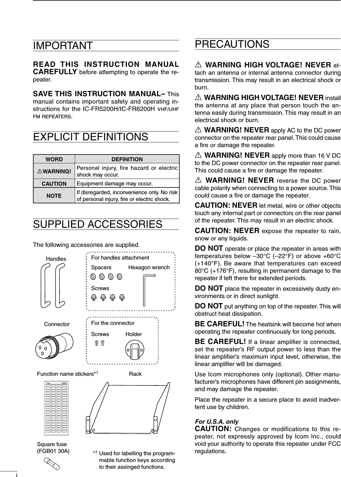
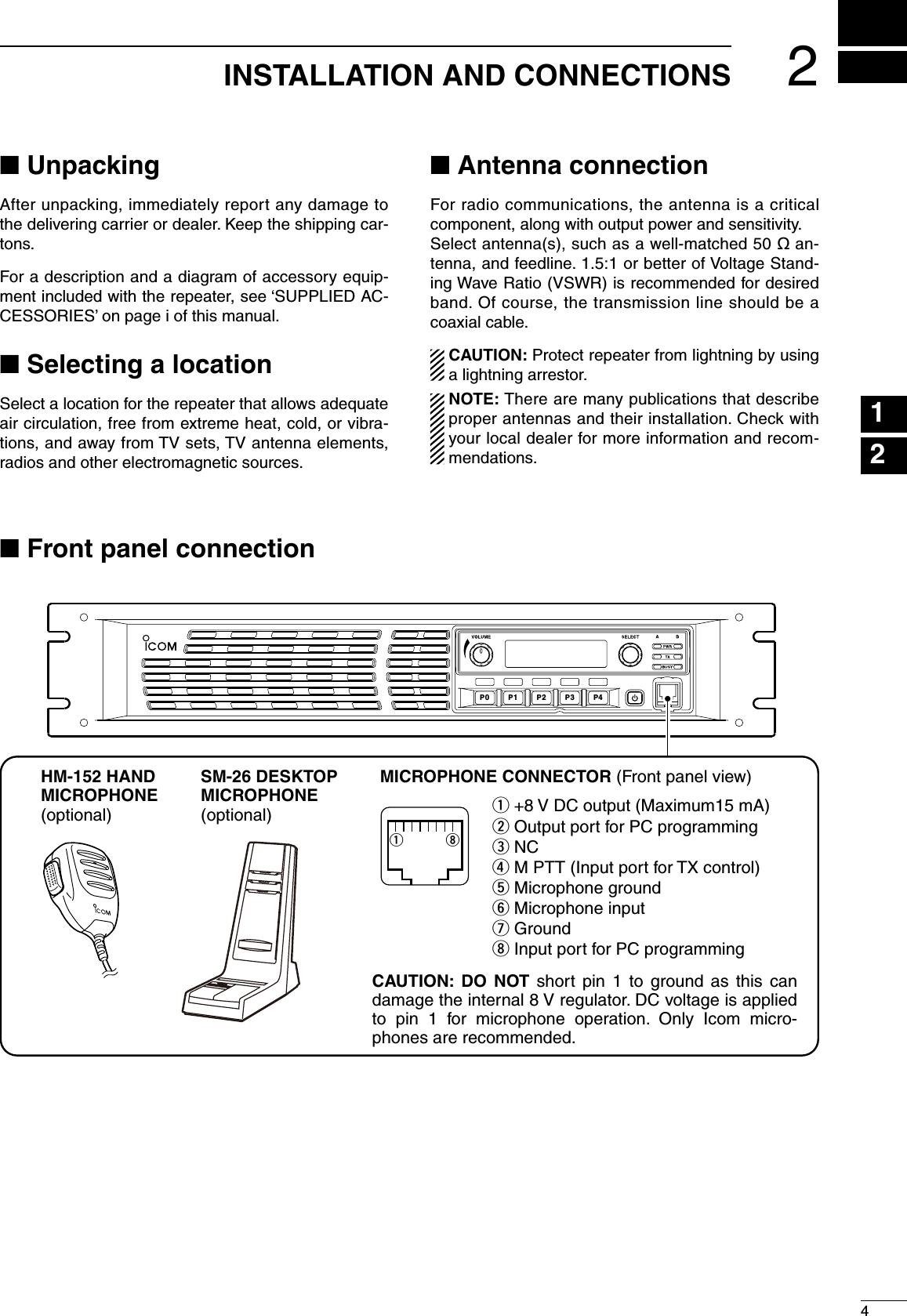
![11PANEL DESCRIPTIONq INTERNAL SPEAKER Monitors received signals.w VOLUME CONTROL [VOLUME] (p. 7) Adjusts the audio output level.e SELECTOR DIAL [SELECT] Rotate to adjust the squelch threshold level, select the operating channel. (Depending on the pre-programmed condition.)r POWER INDICATOR [POWER] ➥ Lights green at ‘A’ module's indicator while the repeater power is turned ON. When a channel extension module is installed: ➥ Lights green at the selected module indicator (‘A’ or ‘B’) while the repeater power is turned ON. ➥ Lights orange at the un-selected module indica-tor (‘A’ or ‘B’) while the repeater power is turned ON.t TRANSMIT INDICATOR [TX] Lights red while transmitting.y BUSY INDICATOR [BUSY] Lights green while receiving a signal or when the noise squelch is open. About [PWR], [TX] and [BUSY] indicators: ‘A’ and ‘B’ modules indicators are available for these indications. ‘A’ module's indicator correspond to the original module, and ‘B’ module's indicator correspond to an extended module.u MICROPHONE CONNECTOR [MIC] This 8-pin modular jack accepts the optional micro-phone. KEEP the [MIC] connector cover attached to the repeater when the optional microphone is not used.iqq +8 V DC output (Max. 15 mA) w Output port for PC programming e NC r M PTT (Input port for TX control) t Microphone ground y Microphone input u Ground i Input port for PC programmingi POWER SWITCH [POWER] ➥ Push to turn the repeater power ON. ➥ Push and hold for 3 sec. to turn the repeater power OFF. When a channel extension module is installed: ➥ While the repeater power is turned ON, push to select the desired module to operate the re-peater as the base station. • The power indicator of the selected module unit lights green.o DEALER-PROGRAMMABLE KEYSDesired functions can be programmed indepen-dently by your dealer. Ask your dealer for details. • Because these keys are programmable, the functions of these keys are unique to each unit.P0P1P2P3P4qw ei uoFunctiondisplayytrn Front panel](https://usermanual.wiki/ICOM-orporated/370500/User-Guide-2519499-Page-6.png)
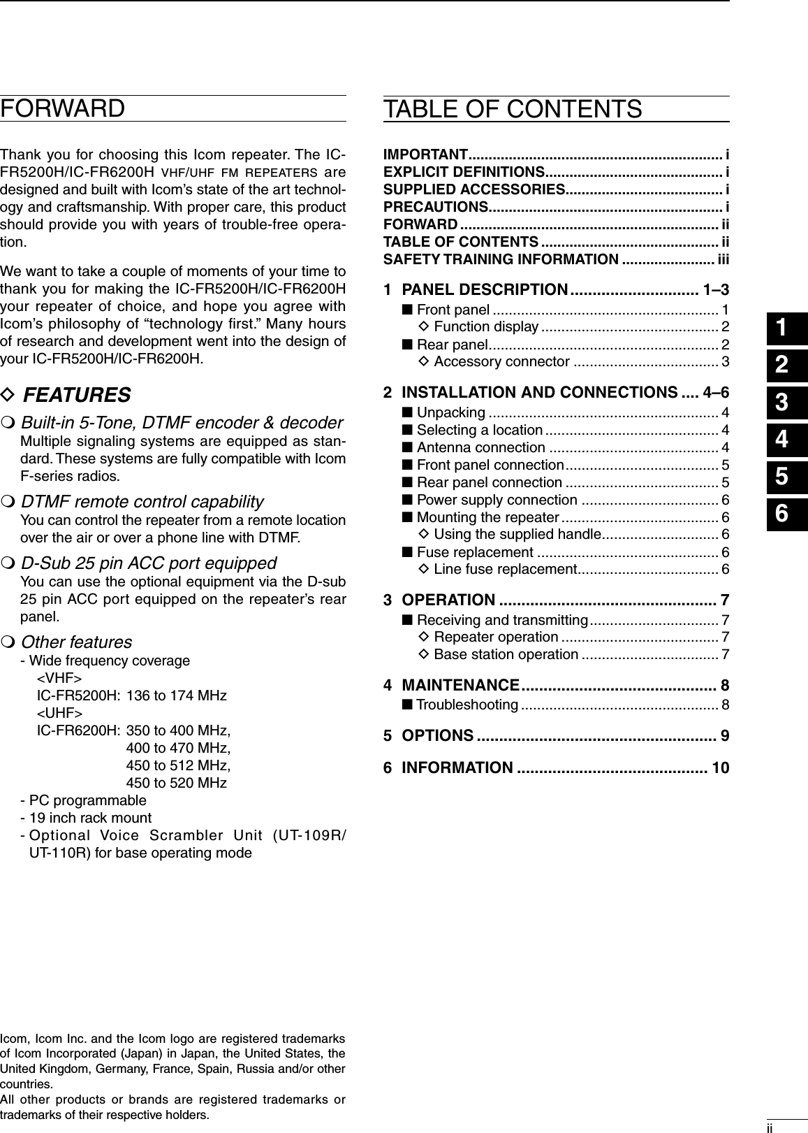
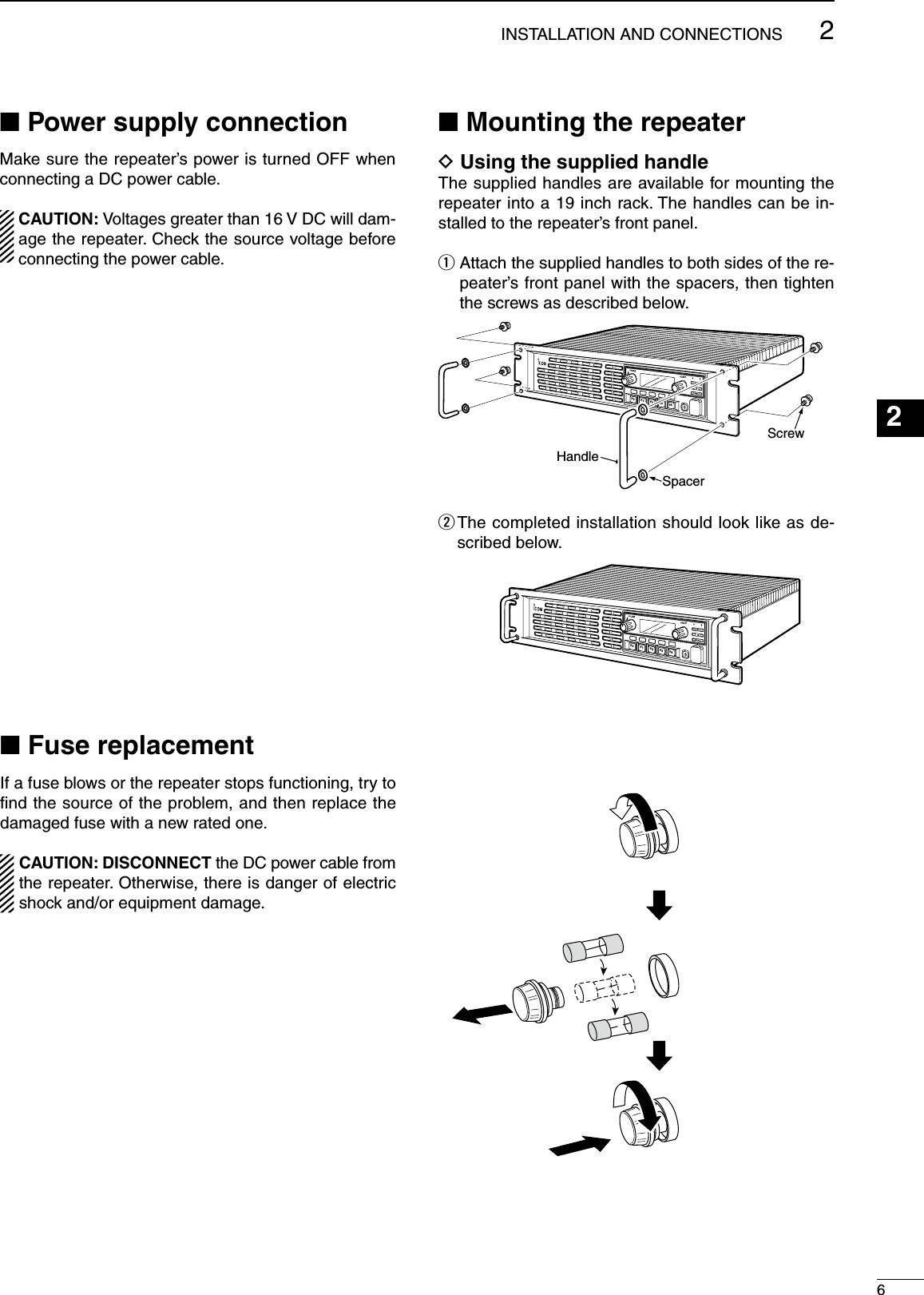
![21PANEL DESCRIPTIONq ACCESSORY CONNECTOR [ACC] Connects to the accessory connector. • See page 3 for accessory connector information.w EXTERNAL SPEAKER CONNECTOR [SPEAKER] Connect the optional SP-22 or SP-35/SP-35L.e RECEIVE ANTENNA CONNECTOR [RX] Connects a receive antenna (impedance: 50 ø) and inputs receiving signals.r TRANSMIT ANTENNA CONNECTOR [TX] Connects a transmit antenna (impedance: 50 ø) and outputs transmit signals.t LAN CONNECTOR [LAN] For an Ethernet connection. Connect the controller to an Ethernet [LAN] port of a PC console through a Hub (or a router). In trunking mode operation, the controller at one end of the chain must be connected. You can con-trol the controller and all others in the chain from the PC console.y BUS CONNECTORS [BUS-1]/[BUS-2] For data communication between the control-lers in trunking mode operation, either [BUS-1] or [BUS-2] can be used. They enable the controllers to be “daisy-chained” together, and form a network that allows trunking and other data to pass among them. u FUSE See page 6 to replace a damaged fuse.i DC POWER CONNECTOR Connects the supplied DC power cable from this connector to an external 13.6 V DC power supply. See page 5 for the connection details.we rytThe optional channel extention modulecan be installed.Ask your dealer for details.The optional trunking/network controllercan be installed.Ask your dealer for details.qwe rty uiACCRX TXLANBUS-2BUS-1FUSEFUSEDC INPUTSPEAKERGND+–¬¬q SIGNAL STRENGTH INDICATOR Indicates relative signal strength level.w LOW POWER INDICATOR Appears when low output power is selected.e AUDIBLE INDICATOR Appears when the channel is in the ‘audible’ (un-mute) condition.r COMPANDER INDICATOR Appears when the compander function is activated.t SCRAMBLER/ENCRYPTION INDICATOR Appears when the voice scrambler/encryption function is activated.y ALPHANUMERIC DISPLAY Shows a variety of text or code information.n Rear panelD Function displayICOM Inc.qwerty123456789101112131415161718192021](https://usermanual.wiki/ICOM-orporated/370500/User-Guide-2519499-Page-7.png)
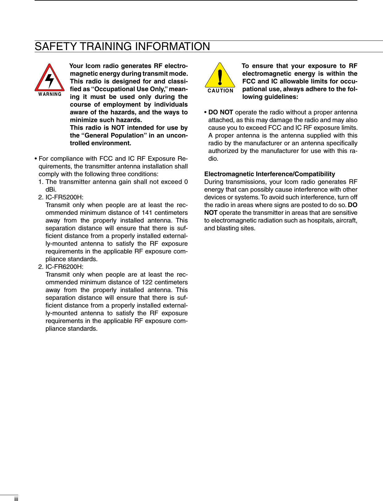
![31PANEL DESCRIPTIOND Accessory connectorq!3!4 @5SpecificationDescriptionPin NamePin No.NCTXDRXDRTSCTSNCGNDMOD INDISC OUTEXT. D/AVCCEXT. A/DNCGNDEXT.I/O 15EXT.I/O 16EXT.I/O 17EXT.I/O 18EXT.I/O 19DATA INEXT.I/O 21AF OUTEXT.I/O 23EXT.I/O 24EXT.I/O 2512345678910111213141516171819202122232425No connectionOutput terminal for serial communication data.Input terminal for serial communication data.Output terminal for request-to-send data.Input terminal for clear-to-send data.No connectionSerial/digital signal groundModulator input from an external terminal unit.Output terminal for AF signals from the AF detector circuit. Output level is fixed, regardless of [AF] control.The desired function can be assigned.*(Default: Null)13.6 V DC outputCustomize A/D input (Not used)No connectionGroundThe desired function can be assigned.* (Default: Null)The desired function can be assigned.*(Default: P0 Monitor Output)The desired function can be assigned.*(Default: Busy Output)The desired function can be assigned.*(Default: Null)The desired function can be assigned.*(Default: EPTT Input)Input terminal for data.The desired function can be assigned.*(Default: Analog Audible Output)The AF detector Output.The desired function can be assigned.*(Default: Mic Mute Output)The desired function can be assigned.*(Default: Null)The desired function can be assigned.*(Default: Mic Hanger Output)———————Input level: 300 mV rmsOutput level: 300 mV rms—Output current: Less than 1 A———+5 V pull up, Active=L+5 V pull up, Active=L+5 V pull up, Active=L+5 V pull up, Active=L+5 V pull up, Active=L—+5 V pull up, Active=L—+5 V pull up, Active=L+5 V pull up, Active=L+5 V pull up, Active=L* The desired function can be assigned using the optional CS-FR5000 c l o n i n g s o f t w a r e . Ask your dealer for details.](https://usermanual.wiki/ICOM-orporated/370500/User-Guide-2519499-Page-8.png)
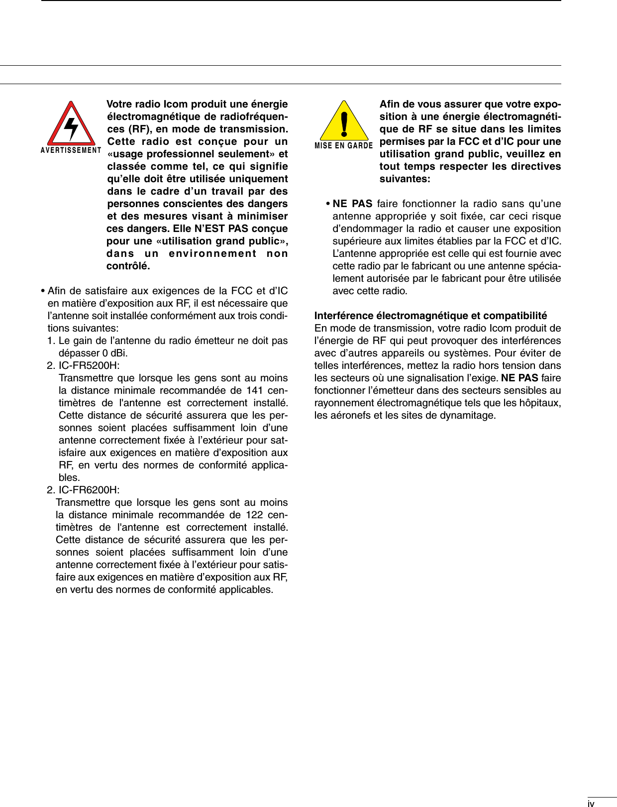
EXTERNAL SPEAKERSP-35/SP-35LConnect a 4 ø external speaker.[TX ANT] (p. 4)ACC CONNECTOR (p. 3)Used for external equipment control.Up to 30 channel modules with controllers can be daisy-chained.RepeaterLANBUS-2 BUS-1 LANBUS-2 BUS-1LANBUS-2 BUS-1 LANBUS-2 BUS-1The illustration below describes one example of a connection for trunking mode operation.](https://usermanual.wiki/ICOM-orporated/370500/User-Guide-2519499-Page-10.png)
![n Receiving and transmittingD Repeater operationAsk your dealer for details of the repeater’s program-ming.➥When the power is turned ON, the [PWR] indicator lights green. (p. 1)➥The [TX] and [BUSY] indicators light simultane-ously while transmitting/receiving a signal. • The [TX] indicator lights red. • The [BUSY] indicator lights green.NOTE: A power amplifier protector is built-in to the repeater. The protector is activated when the re-peater temperature becomes extremely high due to the frequently access to the repeater to reduce the transmit output power level. The output power will return to the normal level when the repeater has cooled down.D Base station operationReceivingq Push [POWER] to turn the power ON.w Set the audio and squelch levels. ➥ Rotate [SELECT]*1 fully counterclockwise in ad-vance. ➥ Rotate [VOLUME] to adjust the audio output level. ➥ Rotate [SELECT]*1 clockwise until the noise dis-appears.e Push [CH Up]*2 or [CH Down]*2 to select the de-sired channel. • When receiving a signal, the [BUSY] indicator lights green and audio is emitted from the speaker. • Further adjustment of [VOLUME] to a comfortable lis-tening level may be necessary at this point.*1 When the [SQL Level Up/Down] key function is assigned to [SELECT].*2 When the [CH Up]/[CH Down] key functions are as-signed.Transmittingq Take the microphone off hook.w Wait for the channel to become clear.e Push and hold [PTT] to transmit, then speak into the microphone at your normal voice level.r Release [PTT] to receive.IMPORTANT: To maximize the audio quality of the transmitted signal:1. Pause briefly after pushing [PTT].2. Hold the microphone 5 to 10 cm (2 to 4 inch) from your mouth, then speak into the microphone at a normal voice level.37OPERATION](https://usermanual.wiki/ICOM-orporated/370500/User-Guide-2519499-Page-12.png)
![48MAINTENANCEn TroubleshootingThe following chart is designed to help you correct problems which are not equipment malfunctions.If you are unable to locate the cause of a problem or solve it through the use of this chart, contact your nearest Icom Dealer or Service Center.123456789101112131415161718192021PROBLEM POSSIBLE CAUSE SOLUTION REF.Power does not come on when [POWER] is pushed.• DC power cable is improperly connected.• Fuse is blown.• Re-connect the DC power cable correctly.• Check for the cause, then replace the fuse with a spare one. pp. 5, 6p. 8No sound comes from the speaker.• Volume level is too low.• The squelch is closed.• The audio mute function is activated.• A selective call or squelch function is acti-vated such as 5-tone call or tone squelch.• The front speaker is set to OFF.• Rotate [VOLUME] clockwise to obtain a suit-able listening level.• While in base operating mode, rotate [SE-LECT] to counterclockwise to open the squelch. (When the [SQL Level Up/Down] key function is assigned to [SELECT].)• Push [MONI] (if assigned) to turn the audio mute function OFF.• Turn the appropriate function OFF.• Turn the front speaker ON using the optional CS-FR5000 cloning software. Ask your dealer for details.p. 7p. 7–––Sensitivity is low and only strong signals are audible.• Antenna feedline or the antenna connec-tor has a poor contact or is short-circuited.• Check and re-connect (or replace if neces-sary), the antenna feedline or antenna con-nector.p. 5Received audio is un-clear or distorted.• Optional voice scrambler is turned OFF.• Scrambler code is not set correctly.• Turn the optional voice scrambler ON.• Reset the scrambler code.––Output power is too low.• Output power is set to Low.• Power amplifier protection circuit is acti-vated.• Push [HIGH/LOW] (if assigned) to select the High power.• Cool down the repeater or stop accessing to the repeater until it has cooled down.––No contact possible with another station.• The other station is using tone squelch.• While in base operating mode, the re-peater is set to duplex.• Turn the tone squelch function ON.• Set the repeater to simplex, when other trans-ceiver is set to simplex.––](https://usermanual.wiki/ICOM-orporated/370500/User-Guide-2519499-Page-13.png)