ICOM orporated 376902 UHF Digital Transceiver User Manual IC F5400D F6400D Series Instructions
ICOM Incorporated UHF Digital Transceiver IC F5400D F6400D Series Instructions
Contents
- 1. User manual Instructions
- 2. User Manual Precautions
- 3. User Manual
User manual Instructions
– 4 –1-1-32 Kamiminami, Hirano-ku, Osaka 547-0003, Japan
Thank you for choosing this Icom product.
READ ALL INSTRUCTIONS carefully and completely
before using this product.
INSTRUCTIONS
VHF DIGITAL TRANSCEIVERS
Iç-F6400D series
UHF DIGITAL TRANSCEIVERS
Iç-F5400D series
SUPPLIED ACCESSORIES
This instruction sheet includes some functions that are
usable only when they are preset by your dealer. The
transceiver may have other functions and operations that
are not described in this instruction sheet. Ask your dealer
for preset function details.
IMPORTANT
NOTE: Some accessories may not be supplied, or the
shape may be different, depending on the transceiver
version.
A key element in the performance of any communication
systems is the antenna. Contact your dealer for information
regarding antennas and how to install them.
ANTENNA
Fuses are installed in the supplied DC power cable. If a fuse
blows, track down the source of the problem, repair it, and
then replace the damaged fuse with a new rated one.
Fuse rating: 20A
USE only 20 A fuses
FUSE REPLACEMENT
If the transceiver becomes dusty or dirty, wipe it clean with a
soft, dry cloth.
DO NOT use harsh solvents such as Benzine or
alcohol, as they may damage the transceiver's
surfaces.
CLEANING
MicrophoneMicrophone
Microphone hanger
and screw set
Microphone hanger
and screw set
Microphone
hanger cable
DC power cable
Sponges*2
Mounting bracket
Flat washers Spring washers
Bracket bolts Mounting screws
(M5×12)
Self-tapping screws
(M5×16)
Nuts
*2
Used for labelling the pro-
grammable function keys
according to their assinged
functions.
Used for the optional unit
installation.
Ask your dealer for details.
*1
OR
Non-self-grounding type Self-grounding type
Function name
stickers*1
A-7312D-1EX Printed in Japan
© 2016 Icom Inc.
– 1 –
Icom, Icom Inc. and the Icom logo are registered trademarks of Icom Incor-
porated (Japan) in Japan, the United States, the United Kingdom, Germany,
France, Spain, Russia, Australia, New Zealand, and/or other countries.
The Bluetooth word mark and logos are registered trademarks owned by Blue-
tooth SIG, Inc. and any use of such marks by Icom inc. is under license.
All other products or brands are registered trademarks or trademarks of their
respective holders.
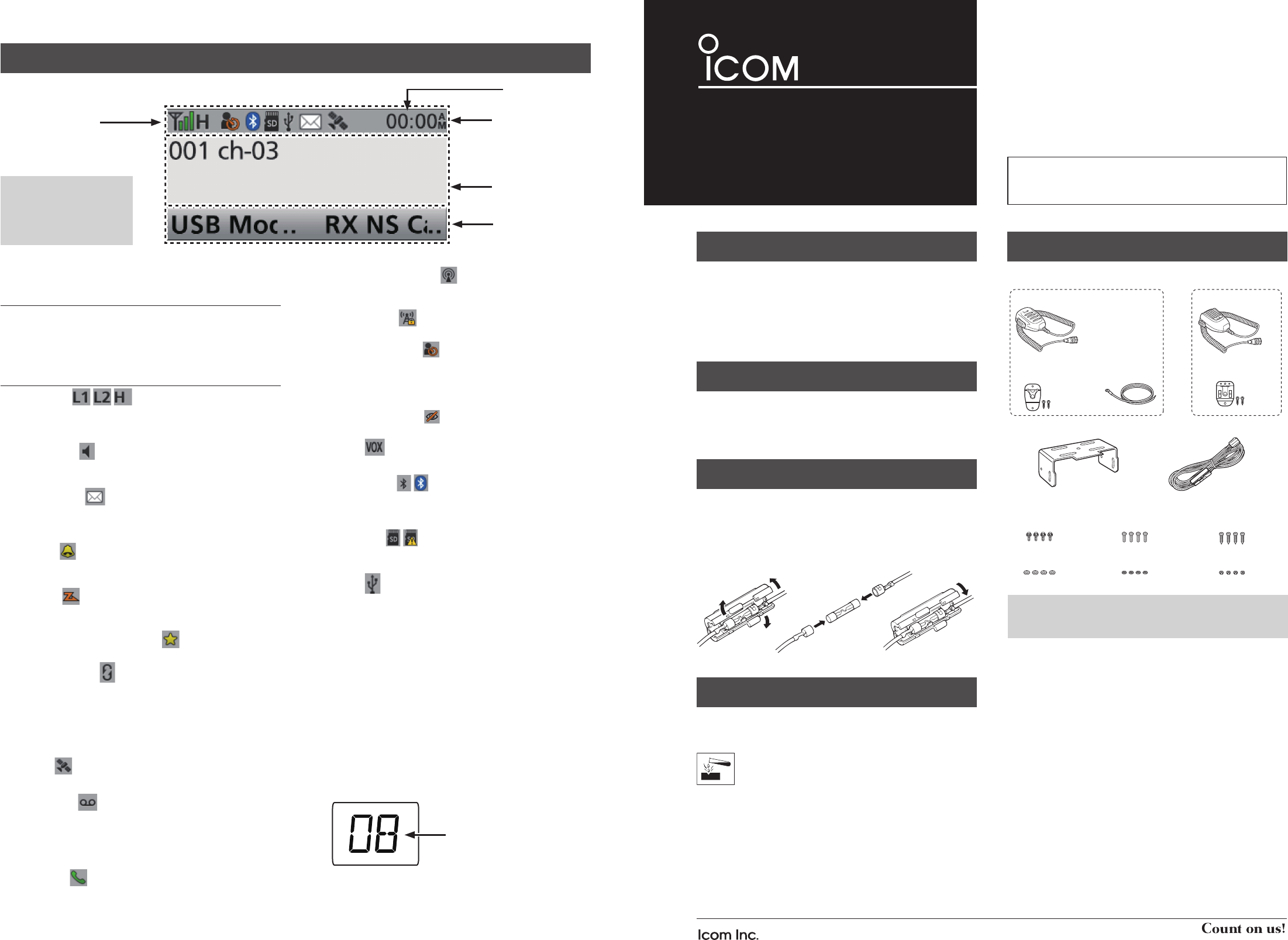
FUNCTION DISPLAY
DIcon Area
Indicators
q SIGNAL STRENGTH INDICATOR
Displays the relative received signal strength.
w CLOCK
Displays the current time.
Icons
POWER ICON
• “L1” is displayed when the output power is set to low.
• “L2” is displayed when the output power is set to mid.
• “H” is displayed when the output power is set to high.
AUDIBLE ICON
Displayed when the channel is in the ‘audible’ (unmute)
mode.
MESSAGE ICON
• Displayed when a received message (Short Data Message or
Status Message) is stored in the message memory.
• Blinks when an unread message is in the message memory.
BELL ICON
Displayed when a matching signal is received, depending
on the presetting.
SCAN ICON
• Displayed while scanning.
• Blinks while a scan is paused.
SCAN TARGET CHANNEL ICON
• Displayed when the channel is selected as a scan target channel.
SCRAMBLER ICON
// for the Analog mode //
• Displayed when the Voice Scrambler function is ON.
• Blinks when receiving a scrambled signal.
// for the Digital mode //
• Displayed when the Voice Encryption function is ON.
• Blinks when receiving an encrypted signal.
GPS ICON
• Displayed when a valid position data is received.
RECORD ICON
• Displayed when the Record function is ON.
• Blinks while recording the audio.
TALK AROUND ICON
Displayed when the Talk Around function is ON.
PHONE ICON
• Displayed when the transceiver is connected to a telephone
network on the selected channel.
• Blinks while receiving a phone call.
BROADCAST CALL ICON
• Displayed when the Broadcast Call function is ON.
• Blinks while receiving a Broadcast Call.
SITE LOCK ICON
Displayed when the Site Lock function is ON.
LONE WORKER ICON
Displayed when the Lone Worker function is ON.
NOISE CANCEL ICON
Displayed when the Noise Cancel function is ON.
SURVEILLANCE ICON
Displayed when the Surveillance function is ON.
VOX ICON
Displayed when the VOX function is ON.
Bluetooth® ICON
• Displayed when Bluetooth® is activated.
• Lights Blue when a Bluetooth® device is connected.
• Does not light when there is no Bluetooth® device connected.
microSD ICON
Displayed when a microSD card is inserted.
“R” is displayed when the microSD card has not been formatted.
USB ICON
Displayed when a USB device is connected.
DText Area
Displays the selected Zone number, Channel number, and
Channel name, if set.
DKey Icon Area
Displays the assigned function of [P1] and [P2].
Ask your dealer about the assigned Software key function.
Icon Area
Text Area
Key Icon Area
q
w
LCD type
NOTE: The screen capture
shows an example.
Display position of each
icon differ, depending on
the function being used.
Displays the selected
channel number.
Segment type
– 2 – – 3 –
DAbout the Status indicator
• Lights red while transmitting.
• Lights green while receiving a signal, or when the squelch is
open.
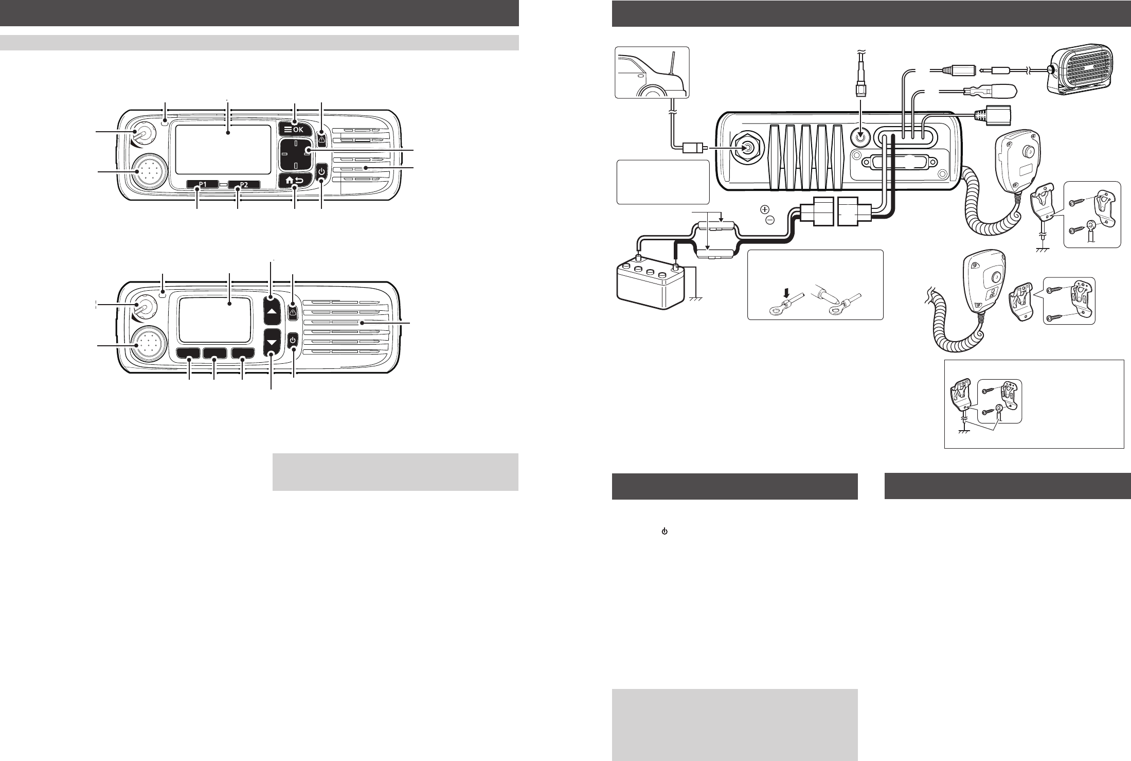
PANEL DESCRIPTION
DAbout the Microphone connector
Connect the supplied or optional microphone.
NEVER
connect non-specifi ed microphones. The pin
assignments may be different and may damage the
transceiver.
Speaker
[VOL]
Status
indicator
Microphone
connector
Function
display
display
[OK] [Emer]
[Emer]
[Up]/[Down]
[Right]/[Left]
[Back]
[P1] [P2] Power key
F1 F2 F3
[VOL]
[VOL]
Microphone
connector
Function
display [Emer]
[Emer]
Power key
Speaker
[Up]
[Up]
[Down]
[F1] [F2] [F3]
Status
indicator
REAR PANEL CONNECTION
LCD type
Segment type
Antenna
12 V
Battery
q
e
r
u
t
Solder
Crimp
NOTE: Use the terminals as shown
below for the cable connections.
w
Black
Red
y
ANTENNA CONNECTOR
Connect to an antenna. Contact
your dealer about antenna selection
and placement.
q
w
D-Sub 25-pin
Connects to an external unit.
t
GPS ANTENNA CONNECTOR
Connect the UX-241 GPS antenna.
e
IGNITION LEAD
Connects to an ignition line.
Do not put pressure on this
lead. Binding to the DC power
cable is recommended.
uMICROPHONE HANGER
For a non-self-grounding type:
Connect the supplied microphone hanger
to the vehicle’s ground for microphone
ON/OFF hook functions.
For a self-grounding type:
The microphone ON/OFF hook functions
can be used without the vehicle’s ground.
r
Connects to a 12 V DC battery.
Pay attention to polarities. NEVER connect
to a 24 V battery.
This will damage the transceiver.
i
i
EXTERNAL SPEAKER JACK
Connect a 4 ~ 8 Ω external speaker.
R
R WARNING! NEVER
remove the fuse
holders from the DC
power cable.
yUSB CABLE
Connects to a PC.
Fuse holders
User supplied
Connect the microphone
hanger to the vehicle’s
ground for microphone
ON and OFF hook
functions when the
HM-221/HM-221T
microphone is used.
When using a self-grounding type:
Non-self-grounding type
Self-grounding type
NOTE: Different functions may have been assigned to the keys by your dealer, except for the Power key.
DTurning power ON
Hold down [ ] for 2 seconds to turn ON the transceiver.
DReceiving and Transmitting
Receiving:
1. Push [Up] or [Down] to select a channel.
2. When receiving a call, rotate [VOL] to adjust the audio
output level to a comfortable listening level.
Transmitting:
1. Wait until the channel is clear to avoid interference.
2. While holding down [PTT], speak at your normal voice
level.
3. Release [PTT] to receive.
IMPORTANT:
To maximize the readability of your signal:
1. After pushing [PTT], pause briefl y before you start
speaking.
2. Hold the microphone 5 ~ 10 cm (2 ~ 4 inches) from your
mouth, then speak at your normal voice level.
BASIC OPERATION OPTIONS
• RMK-5 SEPARATION KIT + OPC-2364 SEPARATION CABLE
Enables you to separately install the transceiver’s main
unit from the front panel for convenient operation.
• RMK-7 DUAL HEAD KIT + OPC-2364 SEPARATION CABLE
Enables you to separately install the transceiver’s main
unit from the front panel for convenient operation.
• SP-30, SP-35, SP-35L EXTERNAL SPEAKERS
Input impedence: 4 Ω
SP-30: Rated input= 20 W, Maximum input = 30 W
SP-35/SP35L: Rated input= 5 W, Maximum input = 7 W
• HM-218, HM-220, HM-220T, HM-221, HM-221T
HAND MICROPHONES
HM-218: Command microphone with a built-in speaker
HM-220: Self-grounding heavy duty microphone
HM-220T: Self-grounding heavy duty DTMF microphone
HM-221: Hand microphone
HM-221T: DTMF microphone
•SM-29 DESKTOP MICROPHONE
•UX-241 GPS ANTENNA
Enables you to use the GPS function.