ICOM orporated 387801 UHF DIGITAL TRANSCEIVER User Manual
ICOM Incorporated UHF DIGITAL TRANSCEIVER
Contents
- 1. User Manual cut antenna
- 2. User manual
- 3. User Manual
User Manual
INSTRUCTIONS
A7397H-1EX-2 Printed in Japan
© 2017 Icom Inc.
1-1-32 Kamiminami, Hirano-ku, Osaka 547-0003, Japan
VHF/UHF DIGITAL TRANSCEIVERS
- 1 -
Thank you for choosing this Icom product.
READ ALL INSTRUCTIONS carefully and completely
before using this product.
This instruction sheet includes some functions that are
usable only when they are preset by your dealer. The
transceiver may have other functions and operations that
are not described in this instruction sheet. Ask your dealer
for preset function details.
IMPORTANT
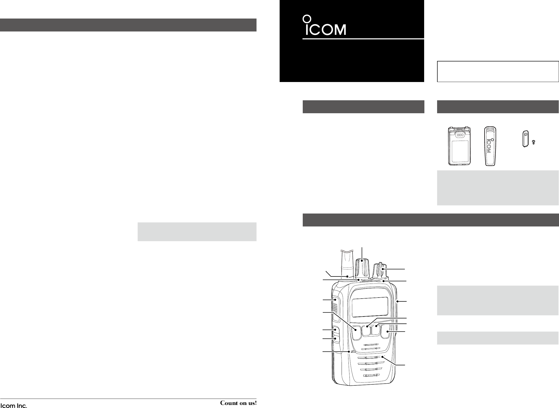
Battery pack Belt clip Connector cover
(with a screw)
SUPPLIED ACCESSORIES
DAbout the Status indicator
• Lights white, then blinks red, yellow, and green when
turning ON the transceiver.
• Lights red while transmitting.
• Lights green while receiving a signal, or when the squelch
is open.
DAbout the Multi-connector
Connects to an optional speaker microphone or headset.
CAUTION:
DO NOT use the transceiver without the
connector cover
or the optional microphone attached.
The transceiver meets IP67 requirements for dust-tight and
waterproof protection only when the connector cover or the
optional microphone is attached.
DAbout the Software key functions
NOTE: Your dealers can assign the Software key
functions to the keys.
PANEL DESCRIPTION
DBATTERY PACKS
• BP-290 li-ion battery pack
Voltage: 7.2 V
Capacity: 1910 mAh (minimum), 2010 mAh (typical)
Battery life: Approximately 13 hours
• BP-291 battery case
Battery case for AA alkaline batteries.
• BP-294 li-ion battery pack
Voltage: 7.2 V
Capacity: 3050 mAh (minimum), 3150 mAh (typical)
Battery life: Approximately 18.5 hours
DCHARGERS
• BC-226 desktop charger + BC-228 ac adapter
For rapidly charging battery packs.
Charging time: Approximately 2.7 hours
L A power adapter may be supplied, depending on the charger’s
version.
• BC-214 multi-charger
+ BC-157S ac adapter, OPC-656 dc power cable
For rapidly charging of up to 6 battery packs simultaneously.
Charging time: Approximately 2.8 hours
L The AD-132N charger adapter may be needed, depending
on the charger's version.
L The BC-157S ac adapter or OPC-656 dc power cable must
be purchased separately.
•BC-219N desktop charger + BC-123S ac adapter
For rapidly charging of battery packs.
Charging time: Approximately 2.5 hours for the BP-290
L A power adapter may be supplied, depending on the charger’s
version.
• BC-225 intelligent desktop charger + BC-123S ac
adapter + RS-BC225 reader software
For rapidly charging battery packs.
You can check the charging status using the RS-BC225.
Charging time: Approximately 2.5 hours for the BP-290
L A power adapter may be supplied, depending on the charger’s
version.
L An USB (Micro-B) cable is required to connect the BC-225 and
a PC with the RS-BC225 installed.
DDC CABLES
•CP-23L cigarette lighter cable
Used when charging battery packs through a 12 V
cigarette lighter socket. For use with the BC-219N.
•OPC-515L, OPC-656 dc power cables
Used when charging battery packs using a 13.8 V DC
power source instead of the power adapter.
OPC-515L: For the BC-219N
OPC-656: For the BC-214
DANTENNAS
• FA-SC26VS, FA-SC27VS, FA-SC56VS, FA-SC57VS
FA-SC26US, FA-SC73US stubby antennas
Shorter VHF or UHF antennas.
FA-SC26VS: 136 ~ 144 MHz FA-SC27VS: 142 ~ 150 MHz
FA-SC56VS: 150 ~ 162 MHz FA-SC57VS: 160 ~ 174 MHz
FA-SC26US: 400 ~ 450 MHz FA-SC73US: 450 ~ 490 MHz
• FA-SC25V, FA-SC28V, FA-SC29V,
FA-SC01U, FA-SC25U, FA-SC57U, FA-SC72U flexible
antennas
VHF or UHF antennas.
FA-SC25V: 136 ~ 150 MHz FA-SC28V: 148 ~ 162 MHz
FA-SC29V: 160 ~ 174 MHz FA-SC01U: 350 ~ 400 MHz
FA-SC25U: 400 ~ 430 MHz FA-SC57U: 430 ~ 470 MHz
FA-SC72U: 470 ~ 520 MHz
• FA-SC61VC, FA-SC61UC cut antennas
• FA-SC62V, FA-SC63V high gain antennas
DBELT CLIPS and BELT HANGERS
• MB-136, MBB-3 belt clip
•MB-96F, MB-96FL, MB-96N belt hangers
DOTHERS
•HM-222 speaker microphone
With an Emergency key.
The HM-222 meets IP68 requirements for waterproof
protection.
•HM-233GP gps speaker microphone
The microphone with high-performance GPS receiver.
• HM-163MC tiepin type microphone
+ EH-15B earphone, SP-26 tube earphone, SP-28 ear
hook type earphone
•SP-32 tube type earphone adapter
For use with EH-15B.
• SP-27 tube earphone, SP-29 ear hook type earphone,
SP-40 earphone + AD-135 earphone adapter
AD-135: Used To connect an earphone to the transceiver’s
multi-connector.
• AD-118 acc adapter
To connect an accessory. See the AD-118 instruction
sheet for details on recommended accessories.
CAUTION: The AD-118 does not have waterproof
protection. When it is connected, NEVER expose the
adaptor and the transceiver to rain, snow or any liquids.
• LC-187, LC-188* carrying case
For use with the BP-290.
• LC-190* carrying case
For use with the BP-294.
* Remove the carrying case from the transceiver before
charging.
• VS-5MC* ptt switch cable
+ HS-94, HS-95, HS-97 headset
VS-5MC: Used to connect a headset to a transceiver.
HS-94: Ear-hook type HS-95: Neck-arm type
HS-97: Throat microphone
* Non-waterproof.
•VS-3 Bluetooth® headset
The Bluetooth headset with a [PTT] switch.
•About the third party Bluetooth headsets:
Icom has checked the PTT operation with some 3M Peltor
headsets such as the WS Headset XP, WS ProTac XP and
WS Alert XP. (Compatibility not guaranteed.)
OPTIONS
Some options may not be available in some countries.
Ask your dealer for details.
Icom, Icom Inc. and the Icom logo are registered trademarks of Icom Incorporated (Japan) in Japan, the United States, the United Kingdom, Germany, France,
Spain, Russia, Australia, New Zealand, and/or other countries.
The Bluetooth word mark and logos are registered trademarks owned by the Bluetooth SIG, Inc. and any use of such marks by Icom Inc. is under license. Other
trademarks and trade names are those of their respective owners.
All other products or brands are registered trademarks or trademarks of their respective holders.
- 4 -
Iç-F52D
Iç-F62D
[Rotary Encoder]
Antenna
Connector
[Emer]*
[PTT]
[Back]*
[OK]*
[F1]*
[F2]*
Speaker
[P1 (Down)]*
[P2 (Up)]*
[VOL]
Status
indicator
Micro-
phone
Multi-
connector
*Dealer assignable
NOTE:
• Some accessories are not supplied, or the shape is
different, depending on the transceiver version.
• Conrmbothbatteryslidinglocksarelockedinplace,
when attaching the battery to the transceiver. Both sliding
locks make a ‘click’ sound when locked.
- 2 - - 3 -
FUNCTION DISPLAY
DIcon Area
Indicators
q SIGNAL STRENGTH INDICATOR
Displays the relative receive signal strength level.
w BATTERY INDICATOR
Displayed or blinks to indicate the battery status.
Indication
Battery
status Full Mid Charging
required
Battery
exhausted
blinks when the battery is exhausted.
Icons
The following icons are displayed in the Icon Area.
SHIFT ICON
Displayed when the Shift function is ON.
L A user can use a Software key’s secondary function in the Shift
mode. Ask your dealer for details.
POWER ICON
Displays the output power level.
• “L1” is displayed when the output power is set to Low.
• “L2” is displayed when the output power is set to Mid.
• “H” is displayed when the output power is set to High.
AUDIBLE ICON
Displayed when the channel is in the ‘audible’ (unmute)
mode.
MESSAGE ICON
• Blinks after messages (Message or Status Message) have
been received.
• Stops blinking when the screen is changed, or any key is
pushed, but is displayed if unread messages are still in the
Message memory.
• Disappears when all messages in the Message memory
have been read.
BELL ICON
Displayed when a matching signal is received, depending
on the presetting.
SCAN ICON
• Displayed when a scan is paused.
• Blinks while scanning.
SCAN TARGET CHANNEL ICON
Displayed when the channel is selected as a scan target channel.
NOTE: The screen is an example.
The displayed position of each icon may differ, depending
on the function being used.
Icon Area
Text Area
Key Display
Area
SCRAMBLER/ENCRYPTION ICON
In the Analog mode:
• Displayed when the Voice Scrambler function is ON.
In the Digital mode:
• Displayed when the Encryption function is ON.
• Blinks when decoding an encrypted signal.
GPS ICON *
• Displayed when valid position data is received.
• Blinks when searching for satellites or calculating position
data.
*HM-233GP is required to use the GPS function.
RECORD ICON
• Displayed when the Record function is ON.
• Blinks while recording audio.
TALK AROUND ICON
Displayed when the Talk Around function is ON.
PHONE ICON
• Displayed when the transceiver is connected to a
telephone network on the selected channel.
• Blinks while receiving a phone call.
BROADCAST CALL ICON *
Displayed when the Broadcast call is received.
* For only the dPMR version.
SITE LOCK ICON
Displayed when the Site Lock function is ON.
LONE WORKER ICON
Displayed when the Lone Worker function is ON.
MOTION SENSOR ICON
Displayed when the Motion Sensor function is ON.
NOISE CANCEL ICON
Displayed when the Noise Cancel function is ON.
SURVEILLANCE ICON
Displayed when the Surveillance function is ON.
VIBRATION ICON
Displayed when the Vibration function is ON.
VOX ICON *
Displayed when the VOX function is ON.
* VS-5MC, VS-3, or other Bluetooth headset is required to use the
VOX function.
Bluetooth® ICON
• “ ” is displayed when Bluetooth is activated.
• “ ” is displayed when a Bluetooth device is connected.
DText Area
Displays the selected Zone number, Channel number, and
Channel name, if set.
DKey Display Area
Displays the names of the function assigned to [P1] and [P2].
L Ask your dealer about the assigned Software key functions.
DTurning ON the transceiver
NOTE:Beforeusingthetransceiverforthersttime,the
battery pack must be fully charged for optimum life and
operation. See the BATTERY CHARGING section of this
sheet.
Rotate [VOL] to turn ON the transceiver.
DReceiving and Transmitting
Receiving:
1. Select a channel.
L Rotate [Selector] or push [Up] or [Down], depending on the
presetting.
2. When receiving a call, rotate [VOL] to adjust the audio
output level to a comfortable listening level.
Transmitting:
CAUTION: Attach an antenna before transmitting.
Transmitting without an antenna may damage the
transceiver.
1. Wait until the channel is clear to avoid interference.
2. While holding down [PTT], speak at your normal voice
level.
3. Release [PTT] to receive.
IMPORTANT:
To maximize the readability of your signal:
1.Afterpushing[PTT],pausebrieflybeforeyoustart
speaking.
2. Hold the microphone 5 to 10 cm (2 to 4 inches) from
your mouth, then speak at your normal voice level.
BASIC OPERATION
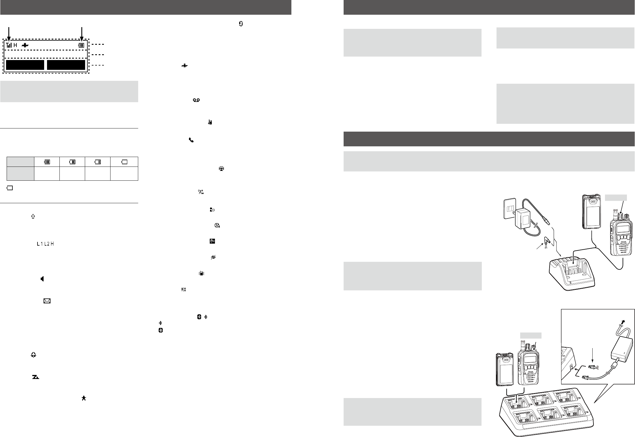
BATTERY CHARGING
DRapid charging with the BC-219N
DRapid charging with the BC-214
You can rapidly charge up to 6 battery packs with the
optional BC-214.
Charging time:
Approximately 2.8 hours
Additionally needed items (purchase separately):
• The BC-157S ac adapter or the OPC-656 dc power cable
• The AD-132N charger adapter (may be supplied with the
charger, depending on the charger version)
CAUTION: NEVER reverse the polarity when connecting
the OPC-656 to a power source. This will ruin the battery
charger.
Red line: +, Black line: _
Battery pack
+ Transceiver
OPC-656
Connect to a
DC power supply:
12 to 16 V, at least 7 A
Red line: +
Black line: _
BC-214
BC-157S
Battery pack
Turn OFF
To an AC outlet
You can rapidly charge the Li-ion battery pack with the
BC-219N.
Charging time:
Approximately 2.5 hours
Additionally needed item (purchase separately):
• A power adapter (may be supplied with the charger,
depending on the charger version) or the OPC-515L/CP-23L dc
power cables.
CAUTION: NEVER reverse the polarity when connecting
the OPC-515L to a power source. This will ruin the battery
charger.
White line: +, Black line: _
NOTE:
• Before detaching or attaching a battery pack, BE SURE to turn OFF the transceiver by rotating [VOL] fully counter clockwise, until it makes a
“click” sound. Otherwise, a transceiver malfunction could occur.
Individual-3
Call High/Low
The OPC-515L
(For a 13.8 V DC
power source) or the
CP-23L (for a 12 V
cigarette lighter
socket) can be used
instead of the power
adapter.
Battery Pack
Power
Adapter*
Battery Pack
+ Transceiver
*
A different type, or no power adapter is
supplied, depending on the charger version.
Turn OFF
To an AC outlet
q w