ICOM orporated 387802 UHF DIGITAL TRANSCEIVER User Manual FA SC61UC 2
ICOM Incorporated UHF DIGITAL TRANSCEIVER FA SC61UC 2
Contents
- 1. User Manual cut antenna
- 2. User manual
- 3. User Manual
- 4. Users Manual
User Manual cut antenna
Thank you for purchasing the
FA-SC61UC
UHF ANTENNA
.
Please read these instructions
thoroughly before using the
FA-SC61UC.
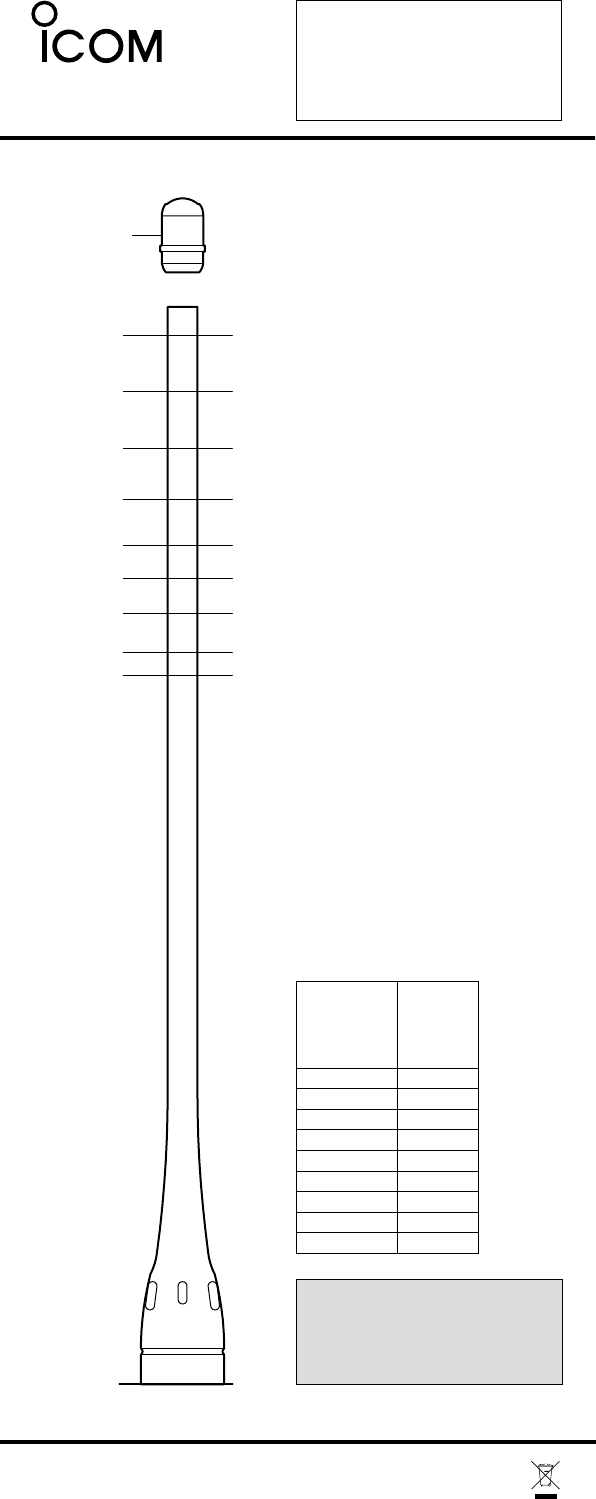
400 MHz
420 MHz
440 MHz
460 MHz
480 MHz
500 MHz
520 MHz
380 MHz
360 MHz
0
Antenna cap
FA-SC61UC
The optimum bandwidth is ±8%
of the tuned frequency.
For optimum performance
tune
to the center transmit
frequency
of the radio.
Cutting Instructions
qAlign the bottom of
the
anten-
na onto the 0 position of
the
cutting guide diagram at left.
wMark the antenna at the
length corresponding
to
the
desired frequency to be
tuned.
FA-SC61UC
A-6532K-1EX-wPrinted in Japan
© 2006-2009 Icom Inc.
eCut the antenna to the
marked length.
• Use a wire cutter that
can
cut at least 1.2 mm (d)
of
piano wire.
rApply adhesive to the top
of
the antenna and attach
the
supplied antenna cap.
• Use of Cemedine Co.
Super-X No. 8008
black
(Icom parts
number:
8950002910) or similar
is
recommended.
Antenna Cutting
Chart
NOTE:
Antenna cap must be inserted after
cutting the element otherwise water
immersion makes the element damaged.
Center
frequency
(MHz)
Length
(mm)
185
175
165
156
148
142
136
129
125
360
380
400
420
440
460
480
500
520
CAUTION:
Making antenna cuts at other than
the prescribed lengths specified could
void the user's authority to operate
the equipment.