ICOM orporated IC-703 HF / VHF Amateur Transceiver User Manual IC 703 INSTRUCTION MANUAL ENGLI
ICOM Incorporated HF / VHF Amateur Transceiver IC 703 INSTRUCTION MANUAL ENGLI
Users Manual
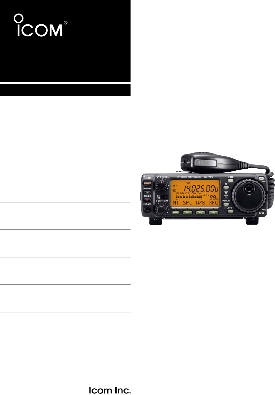
HF/50 MHz
ALL MODE TRANSCEIVER
i703
INSTRUCTION MANUAL

i
FOREWORD
Thank We understand that you have a choice of many
different radios in the market place. We want to take a
couple of moments of your time to thank you for mak-
ing the IC-703 your radio of choice, and hope you
agree with Icom’s philosophy of “technology first.”
Many hours of research and development went into
the design of your IC-703.
FEATURES
❍
DSP features (AF DSP; UT-106
DSP UNIT
required
some version)
❍
All mode capability covering 160–6 m
❍
9.0–15.87 V operation
❍
Compact with detachable front panel
❍
±0.5 ppm of high frequency stability
❍
Built in antenna tuner
❍
Simple band scope function
IMPORTANT
READ THIS INSTRUCTION MANUAL
CAREFULLY before attempting to operate the
transceiver.
SAVE THIS INSTRUCTION MANUAL. This
manual contains important safety and operating in-
structions for the IC-703.
EXPLICIT DEFINITIONS
RWARNING RF EXPOSURE! This device emits
Radio Frequency (RF) energy. Extreme caution should be
observed when operating this device. If you have any
questions regarding RF exposure and safety standards
please refer to the Federal Communications Commission
Office of Engineering and Technology’s report on Evalu-
ating Compliance with FCC Guidelines for Human Radio
Frequency Electromagnetic Fields (OET Bulletin 65).
RWARNING HIGH VOLTAGE! NEVER attach an
antenna or internal antenna connector during transmis-
sion. This may result in an electrical shock or burn.
RNEVER apply AC to the [DC13.8V] receptacle on the
transceiver rear panel. This could cause a fire or damage
the transceiver.
RNEVER apply more than 16 V DC, such as a 24 V
battery, to the [DC13.8V] receptacle on the transceiver
rear panel. This could cause a fire or damage the trans-
ceiver.
RNEVER let metal, wire or other objects touch any in-
ternal part or connectors on the rear panel of the trans-
ceiver. This may result in an electric shock.
NEVER expose the transceiver to rain, snow or any liquids.
AVOID using or placing the transceiver in areas with tem-
peratures below –10°C (+14°F) or above +60°C (+140°F).
Be aware that temperatures on a vehicle’s dashboard can
exceed 80°C (+176°F), resulting in permanent damage to
the transceiver if left there for extended periods.
AVOID placing the transceiver in excessively dusty envi-
ronments or in direct sunlight.
AVOID placing the transceiver against walls or putting
anything on top of the transceiver. This will obstruct heat
dissipation.
Place unit in a secure place to avoid inadvertent use by
children.
During mobile operation, DO NOT operate the transceiver
without running the vehicle’s engine. When the trans-
ceiver’s power is ON and your vehicle’s engine is OFF,
the vehicle’s battery will soon become exhausted.
Make sure the transceiver power is OFF before starting
the vehicle. This will avoid possible damage to the trans-
ceiver by ignition voltage spikes.
During maritime mobile operation, keep the transceiver
and microphone as far away as possible from the magnetic
navigation compass to prevent erroneous indications.
BE CAREFUL! The rear panel will become hot when op-
erating the transceiver continuously for long periods.
BE CAREFUL! If a linear amplifier is connected, set the
transceiver’s RF output power to less than the linear am-
plifier’s maximum input level, otherwise, the linear ampli-
fier will be damaged.
Use Icom microphones only (supplied or optional). Other
manufacturer’s microphones have different pin assign-
ments, and connection to the IC-703 may damage the
transceiver.
Beat signals may be heard on some frequencies.
These will occur as a result of circuit construction.
For U.S.A. only
Caution: Changes or modifications to this transceiver, not
expressly approved by Icom Inc., could void your authority
to operate this transceiver under FCC regulations.
PRECAUTION
WORD DEFINITION
RWARNING Personal injury, fire hazard or electric
shock may occur.
CAUTION Equipment damage may occur.
NOTE
If disregarded, inconvenience only. No
risk or personal injury, fire or electric
shock.
ii
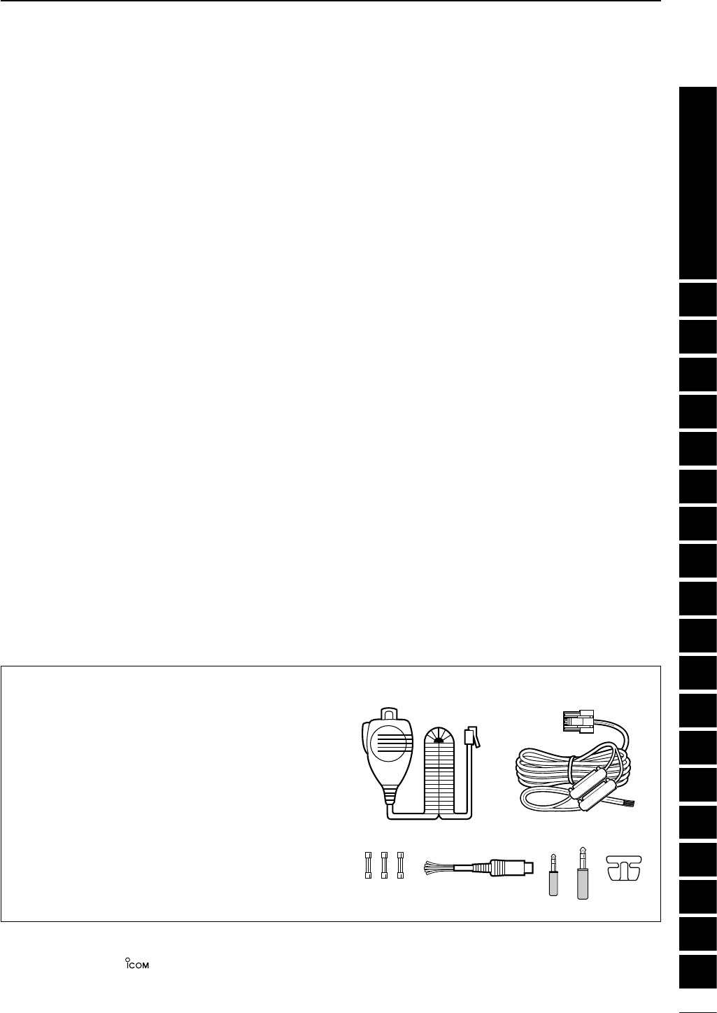
SUPPLIED ACCESSORIES
The transceiver comes with the following accessories.
Qty.
qHand microphone (HM-103) .............................. 1
wDC power cable (OPC-1229) ............................. 1
eSpare fuse (FGB 4 A) ........................................ 3
rACC cable ...........................................................1
t3.5 (d) mm plug ...................................................1
y6.5 (d) mm Electronic keyer plug.........................1
uMicrophone hanger..............................................1
TABLE OF CONTENTS
q
er
w
ty u
Icom, Icom Inc. and the logo are registered trademarks of Icom Incorporated (Japan) in the United States, the United King-
dom, Germany, France, Spain, Russia and/or other countries.
FOREWORD …………………………………………… i
IMPORTANT ……………………………………………i
EXPLICIT DEFINITIONS ……………………………… i
PRECAUTION …………………………………………i
TABLE OF CONTENTS ……………………………… ii
QUICK REFERENCE GUIDE ……………… I–X
■Installation ………………………………………… I
1. Grounding your Shack ……………………… I
2. Installing your DC Power Supply ………… I
3. Installing lightning protection ……………… II
4. Installing your antenna system …………… II
5. Connect other peripheral equipment …… III
■Operation ………………………………………… III
1. Voice ………………………………………… III
2. CW…………………………………………… III
3. Other convenient items …………………… IV
■Your first contact ………………………………… IV
DGetting started ………………………………… IV
DJust listening …………………………………… V
1. Select the desired band …………………… V
2. Tune to the desired frequency …………… V
3. Adjust audio output ………………………… V
DWhat are you hearing? ……………………… VI
1. Verify mode ………………………………… VI
2. Reducing interference
(Some functions may require
an optioanl unit depending on version) … VI
■Ready to call CQ? ……………………………… IX
1. Setting up your Mic Gain ………………… IX
2. Speech compressor………………………… X
1 PANEL DESCRIPTION ………………… 1–10
■Front panel ………………………………………… 1
■Multi-function switches …………………………… 4
DM1 functions …………………………………… 4
DM2 functions …………………………………… 4
DM3 functions …………………………………… 4
DM4 functions …………………………………… 5
DS1 functions …………………………………… 6
DS2 functions …………………………………… 6
DS3 functions …………………………………… 6
DS4 functions
(UT-106 is required for some version) ……… 6
■Rear panel ………………………………………… 7
DDATA socket …………………………………… 8
DACC socket……………………………………… 8
■Function display…………………………………… 9
■Microphone (HM-103) ………………………… 10
2
INSTALLATION AND CONNECTIONS
… 11–16
■Unpacking………………………………………… 11
■Selecting a location……………………………… 11
■Grounding………………………………………… 11
■Antenna connection……………………………… 11
■Installation ……………………………………… 12
DSingle body mounting ………………………… 12
DStand …………………………………………… 12
DFront panel separation ……………………… 12
DFront panel mounting ………………………… 12
■Required connections…………………………… 13
■Advanced connections ………………………… 14
■DC Power voltage ……………………………… 15
■DC Power supply connections ………………… 15
■Battery connections …………………………… 15
■External antenna tuners and linear amplifier … 16
1
2
3
4
5
6
7
8
9
10
11
12
13
14
15
16
17
18
19
Quick Reference

iii
3 BASIC OPERATION ……………………17–26
■When first applying power (CPU resetting)…… 17
DM1 display selection ………………………… 17
■Initial settings …………………………………… 17
■VFO description ………………………………… 18
DThe differences between VFO and
memory mode ………………………………… 18
■Frequency setting ……………………………… 19
■Operating mode selection ……………………… 23
■Volume setting …………………………………… 23
■Squelch and receive (RF) sensitivity ………… 24
■Dial lock function ………………………………… 25
■Basic transmit operation ……………………… 25
DTransmitting …………………………………… 25
DMaximum output power ……………………… 25
DSetting output power ………………………… 26
DSetting microphone gain……………………… 26
4 RECEIVE AND TRANSMIT …………… 27–45
■Operating SSB…………………………………… 27
DConvenient functions for receive …………… 27
DConvenient functions for transmit …………… 27
■Operating CW …………………………………… 28
DConnections for CW ………………………… 28
DCW operation ………………………………… 29
DConvenient functions for receive …………… 30
DConvenient functions for transmit …………… 30
DCW reverse mode …………………………… 30
DCW pitch control ……………………………… 31
DElectronic CW keyer ………………………… 31
DCW side tone function………………………… 32
DKeyer set mode ……………………………… 32
■Memory keyer functions………………………… 33
DMemory keyer send menu …………………… 34
DEditing a memory keyer ……………………… 35
DContest number set mode …………………… 36
DMemory keyer set mode……………………… 37
■Operating RTTY ………………………………… 38
DConnections for RTTY (FSK)………………… 38
DRTTY (FSK) operation ……………………… 38
DConvenient functions for receive …………… 39
DRTTY reverse mode ………………………… 39
DPresetting for RTTY ………………………… 40
DRTTY tone set mode ………………………… 40
■Operating AM …………………………………… 41
DConvenient functions for receive …………… 41
DConvenient functions for transmit …………… 41
■Operating FM …………………………………… 42
DConvenient functions for receive …………… 42
DConvenient functions for transmit …………… 42
DTone squelch operation ……………………… 43
DTone scan operation ………………………… 43
DFM tone set mode …………………………… 44
■Repeater operation ……………………………… 45
5 FUNCTION FOR RECEIVE …………… 46–50
■Simple band scope ……………………………… 46
■Preamp and attenuator ………………………… 46
■RIT function ……………………………………… 47
■IF shift function ………………………………… 47
■Noise blanker …………………………………… 48
DNoise blanker level set mode ……………… 48
■AGC time constant ……………………………… 48
■Optional filter selection ………………………… 49
■Peak meter hold ………………………………… 50
■DSP Functions (may require an optional unit
depending on version) ………………………… 50
DANF (Automatic Notch Filter) function ……… 50
DNR (Noise Reduction) function ……………… 50
6
FUNCTION FOR TRANSMIT
…………… 51–55
■Split frequency operation ……………………… 51
DQuick split function …………………………… 52
■Meter selection ………………………………… 52
■VOX operation …………………………………… 53
DVOX set mode ………………………………… 53
■Speech compressor …………………………… 54
DCompression level set mode ………………… 54
■SWR………………………………………………… 55
DMeasuring SWR ……………………………… 55
7 MEMORY OPERATION ………………… 56–60
■Memory channels ……………………………… 56
■Memory channel selection……………………… 56
■Memory programming ………………………… 57
■Memory clearing ………………………………… 58
■Frequency transferring ………………………… 58
■Memory names ………………………………… 59
■Memo pads ……………………………………… 60
8 SCAN OPERATION …………………… 61–63
■Scan types ……………………………………… 61
■Preparation ……………………………………… 61
■Programmed scan operation…………………… 62
■Memory scan operation ………………………… 62
■Select memory scan operation ………………… 63
■Priority watch …………………………………… 63
9 ANTENNA TUNER OPERATION……… 64–66
■Antenna tuner operation ……………………… 64
DInternal antenna tuner………………………… 64
DTuner operation ……………………………… 64
DOptional external tuner operation …………… 65
DOptional AT-180
AUTOMATIC ANTENNA TUNER
operation ……… 65
DOptional AH-4
AUTOMATIC ANTENNA TUNER
operation ……… 66
TABLE OF CONTENTS

iv
10 DATA COMMUNICATION …………… 67–70
■Connections for packet ………………………… 67
DWhen connecting to [DATA] socket ………… 67
DWhen connecting to [ACC] socket ………… 67
DWhen connecting to [MIC] connector ……… 67
■Packet (AFSK) operation ……………………… 68
D
Frequency indication during AFSK operation …
68
DSSB-D mode selection ……………………… 69
DCarrier point setting…………………………… 69
DAdjusting the transmit signal from the TNC… 70
11 CONTROL COMMAND ……………… 71–73
■Remote jack (CI-V) information ……………… 71
DCI-V connection example ……………………… 71
DData format ……………………………………… 71
D
Command table ……………………………… 72
DBand stacking register ……………………… 73
DCodes for memory keyer contents ………… 73
DCodes for memory name contents ………… 73
12 SET MODE …………………………… 74–82
■General …………………………………………… 74
DQuick set mode operation …………………… 74
DInitial set mode operation …………………… 74
■Quick set mode items…………………………… 75
■Initial set mode items …………………………… 76
1 Maximum output power setting ………… 76
2 Power save setting ……………………… 76
3 Simple mode setting ……………………… 76
4 Mode availability ………………………… 76
5 Output power setting for mode ………… 76
6 Confirmation beeps ……………………… 77
7 Band edges beeps ……………………… 77
8 Beep level adjustment …………………… 77
9 Beep audio level limit …………………… 77
10 CW carrier point setting ………………… 77
11 CW side tone level ……………………… 77
12 CW side tone level limit ………………… 77
13 SSB/CW frequency shift setting ………… 78
14 Display backlighting ……………………… 78
15 Key/switch backlighting ………………… 78
16 Light timer setting ………………………… 78
17 LED brightness …………………………… 78
18 Automatic power OFF …………………… 78
19 Current intercept point …………………… 79
20 RF gain/squelch control ………………… 79
21 Sub dial setting …………………………… 79
22 Optional filter selection…………………… 79
23 Peak meter hold setting ………………… 79
24 Quick split function ……………………… 79
25 Split lock function ………………………… 80
26 Split offset frequency …………………… 80
27 Scan resume condition…………………… 80
28 Scanning speed…………………………… 80
29 [UP]/[DN] speed ………………………… 80
30 Noise blanker in AM mode ……………… 80
31 Available memo pads …………………… 80
32 Power ON check function ……………… 81
33 Auto tune start function ………………… 81
34 PTT tune function ………………………… 81
35 Tuner switch condition …………………… 81
36 Packet data speed ……………………… 81
37 Voice synthesizer language……………… 82
38 Voice synthesizer speed ………………… 82
39 S-meter level speech …………………… 82
40 CI-V address setting ……………………… 82
41 CI-V data transffer rate…………………… 82
42 CI-V transceive …………………………… 82
43 CI-V operating frequency data length … 82
13 MAINTENANCE …………………………… 83
■Fuse replacement ……………………………… 83
■Memory backup ………………………………… 83
■Cleaning ………………………………………… 83
14 TROUBLESHOOTING………………… 84–85
15 OPTIONAL UNIT
INSTALLATIONS AND SETTINGS … 86–89
■Opening the transceiver case ………………… 86
■UT-102
VOICE SYNTHESIZER UNIT
……………… 86
DOperation ……………………………………… 86
■IF filter …………………………………………… 87
■UT-106
DSP RECEIVER UNIT
…………………… 88
■MB-72
CARRYING HANDLE
……………………… 88
■AT-180 internal switch description …………… 89
16 SPECIFICATIONS ………………………… 90
■General …………………………………………… 90
■Transmitter ……………………………………… 90
■Receiver ………………………………………… 90
■Antenna tuner …………………………………… 90
17 OPTIONS ……………………………… 91–92
18 MENU GUIDE …………………………93–94
19 ABOUT CE……………………………… 95–96
TABLE OF CONTENTS
1
2
3
4
5
6
7
8
9
10
11
12
13
14
15
16
17
18
19
Quick Reference
I
QUICK REFERENCE GUIDE
■Installation
1. Install a ground system for DC noise suppression
and RFI suppression
2. Install your DC power supply
3. Install lightning protection. This will help protect
more than your gear.
4. Install and connect an antenna system for the ap-
propriate bands of operation
5. Connect other peripheral equipment. This includes
microphones, headsets, TNC, amplifiers and any
other equipment necessary to make your shack
complete.
Although your radio will operate by connecting the DC
power supply and antenna, it is necessary to have a
good ground system in your shack. A ground connec-
tion is the electrical contact between the common
point of an electrical or electronic system and the
earth.
A good earth ground is necessary to prevent electrical
shock, eliminate problems from RFI and DC noise.
With more electronic devices being used today, it is
also important to reduce RFI and EMI. Although you
may not see interference in your shack, without a
grounding system, your neighbours may experience
interference. Even though many of these devices are
Part 15, where they must accept interference from
their surrounding environment, it is best to eliminate
as much of the possible interference from your shack.
If you do not have a grounding system for your shack,
depending on the location of your shack, basement or
ground floor, a good ground system can be as simple
as a couple of ground rods driven 6 to 8 feet into the
soil. When installing your IC-703 to your grounding
system, the shortest most direct connection is recom-
mended.
NOTE: There are many publications covering
proper grounding techniques. Check with your local
dealer for more information and recommendations.
RWARNING!: NEVER ground station equip-
ment or antennas to house gas lines. NEVER at-
tach ground lines to plastic (pvc) pipe.
DSome Symptoms if inadequate grounding
a. Poor DC Ground
50/60 Hz hum on the audio either Rx or Tx without
the antenna connected.
If you feel a tingling sensation when you touch a
metal surface. Surfaces such as the cover of your
radio or power supply.
b. Poor RF Ground
While transmitting and you feel a tingling sensation
when you touch a metal surface. Surfaces such as
the cover of your radio or power supply.
While transmitting, you experience interference to
other electronic devices, such as the telephone,
television or stereo audio systems.
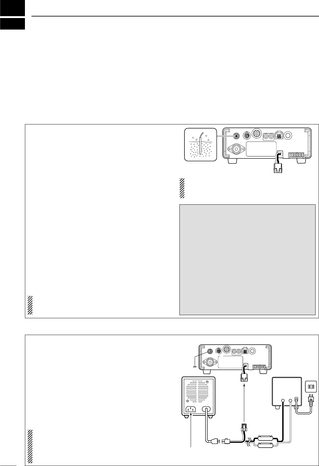
The DC power supply is a device used to convert
110/220 V AC, also know as Household current, to a
steady source of 13.8 V DC.
The perfect match to your IC-703 is the PS-125. This
plug and play unit plugs into the DC power recepta-
cle using an optional OPC-1248 located on the rear
of the radio.
Or connect the supplied DC power cable (OPC-1229)
to the appropriate color coded terminals, then insert
the DC connector into the DC power receptacle lo-
cated on the rear of the radio.
NOTE: Although the power supply current require-
ment is quite low during receiving, this not the case
when you transmit. With many electrical devices in
the shack, it is very important to verify the electrical
circuit is not overloaded.
1. Grounding your Shack
2. Installing your DC Power Supply
AC cable
AC
outlet
A DC power
supply*
Black
_ Red
+
PS-125
DC power cable
Ground
4 A fuses
Transceiver
to DC
power
receptacle
Supplied
OPC-1229
Optional
OPC-1248
Connect to an AC outlet
using the supplied AC cable.
*13.8 V;
at least 3.0 A
continuous
II
QUICK REFERENCE GUIDE
3. Installing lightning protection
Although you may not live in an area with high occur-
rence for lightning storms, it is always wise to take
precautions for lightning or static discharges. Proper
lightning protection not only offers protection to the
ham gear, but the shack and most importantly the op-
erator.
NOTE: There are many publications covering
proper lightning protection, check with your local
dealer for more information and recommendations.
Whether your IC-703 is your first radio or one of
many, one of your key elements in a great shack is
the antenna system. There is a connection on the
back of your IC-703, for HF and 6 m. If you are using
one antenna for HF and 6 m, for simplicity, connect
the antenna coax to ANT.
Your IC-703 is equipped with an internal antenna
tuner (ATU) for operation on 160–6 m. This ATU is de-
signed to work with an unbalanced 50 Ωfeedline. The
purpose of the internal antenna tuner is to match the
impedance of your antenna system to as close to a
50 Ωload as possible. This ATU will not operate with
a long wire or ladder line (450 Ωor other balanced
feedlines). An external ATU such as the AH-4 would
be necessary for this kind of operation.
PL-259 CONNECTOR INSTALLATION EXAMPLE
30 mm ≈9⁄8in 10 mm ≈3⁄8in 1–2 mm ≈1⁄16 in
RWARNING: Although a mag mount antenna
works great on a vehicle, DO NOT use the IC-703
with this type of antenna.
CAUTION: Although your IC-703 has protection to
drop down power with a high SWR, this does not
completely protect the transceiver from transmis-
sion without an antenna. Make sure you have an
antenna connected whenever you transmit with
your radio.
NOTE: There are many publications covering
proper antennas and their installation, check with
your local dealer for more information and recom-
mendations.
30 mm
10 mm (soft solder)
10 mm
1–2 mm
solder solder
Soft
solder
Coupling ring
Slide the coupling ring
down. Strip the cable
jacket and soft solder.
Slide the connector
body on and solder it.
Screw the coupling
ring onto the
connector body.
Strip the cable as
shown at left. Soft
solder the center con-
ductor.
q
w
e
r
Antenna SWR
Each antenna is tuned for a specified frequency
range and SWR may be increased out-of-range.
When the SWR is higher than approx. 2.0:1, the
transceiver’s power drops to protect the final tran-
sistors. In this case, an antenna tuner is useful to
match the transceiver and antenna. Low SWR al-
lows full power for transmitting even when using the
antenna tuner. The IC-703 has an SWR meter to
monitor the antenna SWR continuously.
ANTENNA
Connect a HF/50MHz antenna
Impedance: 50Ω
4. Installing your antenna system
Quick Reference
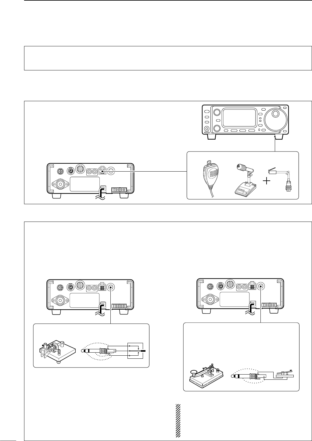
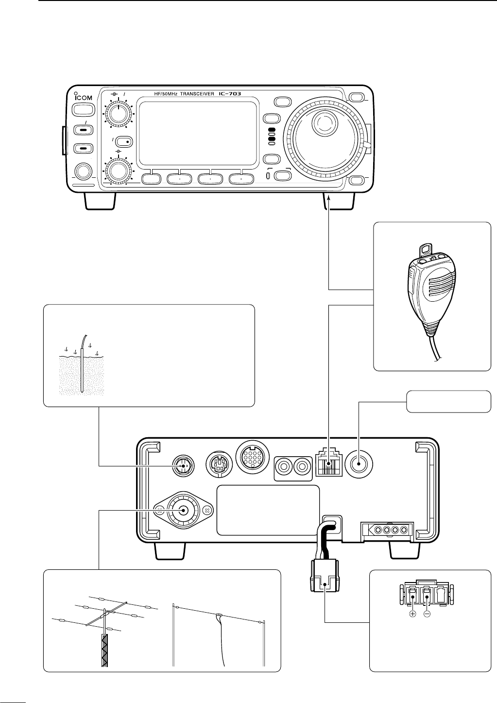
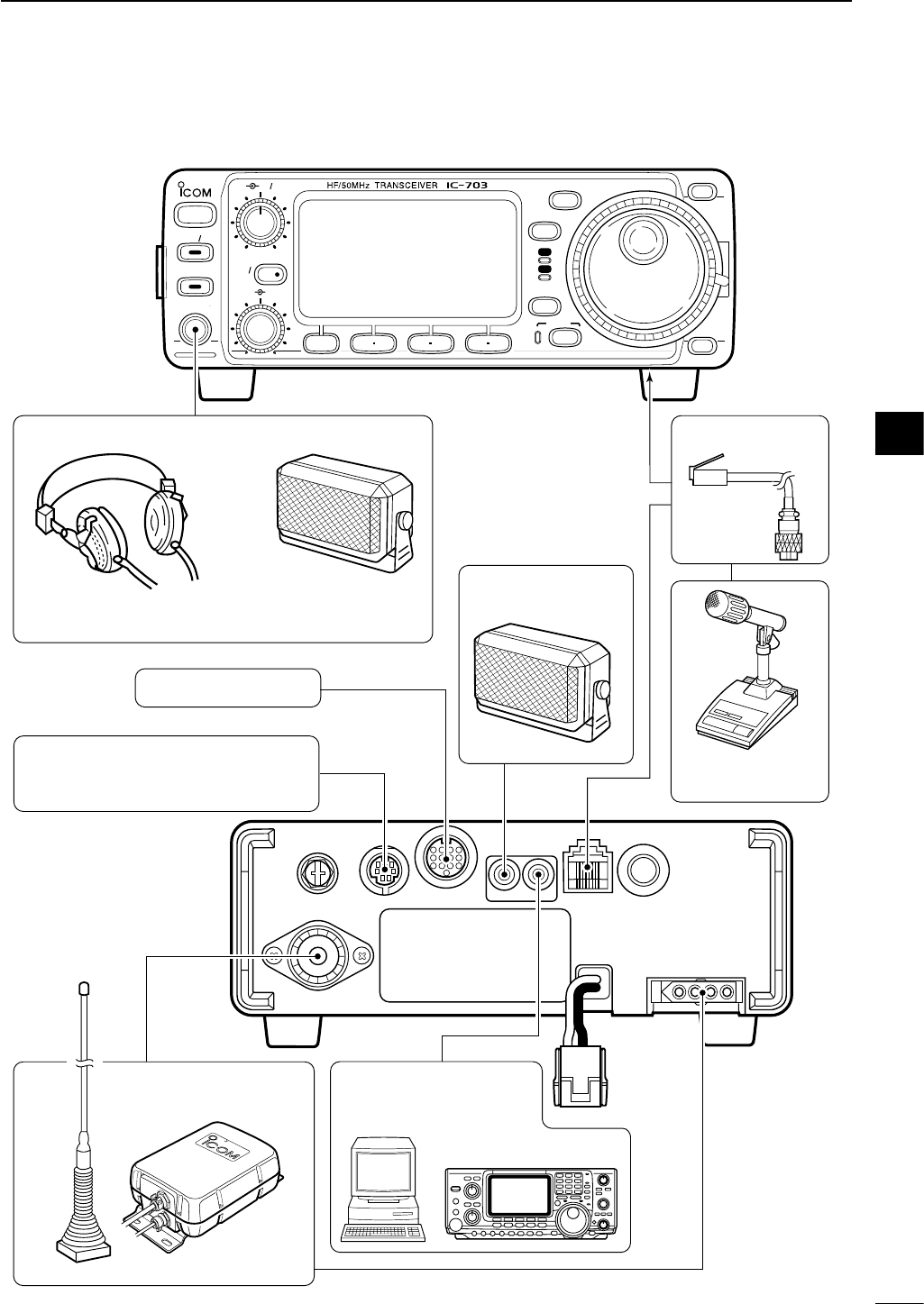
Microphones: Connect the microphone to the modu-
lar-type connector bottom of the front panel or back
of the radio.
Rear panel
Front panel
MICROPHONES
HM-103 SM-20 OPC-589
III
QUICK REFERENCE GUIDE
5. Connect other peripheral equipment
Everyone has his or her favorite ad-on gear; now is
the time to connect this gear! We will cover the basic
devices that can be connected to your IC-703.
If you do not see the particular item you are wanting
to connect, refer to the Advance Connections section
starting on page 14.
■Operation
1. Voice
CW Key: There are several types of keys or keyers
that can be used with your IC-703.
a. Iambic Key paddle: Use a 6.35(d) mm (1⁄4″) stereo
plug and connect to the [KEY] jack located on the
rear of the radio.
b. Straight Key: Use a 6.35(d) mm (1⁄4″) mono plug
and connect key to the back of the radio.
c. External Keyer: Use a 6.35(d) mm (1⁄4″) mono
plug and connect to the back of the radio.
d. Computer Keying: Use a 6.35(d) mm (1⁄4″) mono
plug and connect to the back of the radio.
NOTE: You will need to select the type of keyer you
are using in the keyer set mode. There are many
advanced CW functions in this set mode. Until you
have a full understanding of these functions
change only the items necessary.
Rear panel
CW KEY
A straight key can be used when the internal
electronic keyer is turned OFF in keyer set
mode. (p. 32)
When connecting a straight key or else
(+)
(_)
Rear panel
CW KEY
(dot)
(com)
(dash)
When connecting a paddle
2. CW
IV
QUICK REFERENCE GUIDE
3. Other convenient items
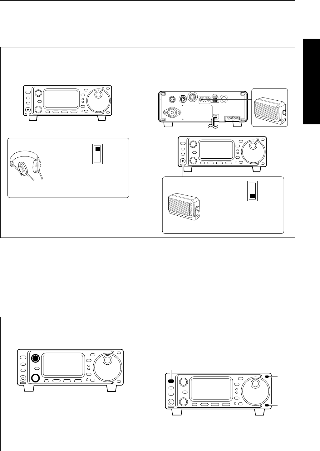
Headphones:
A 3.5(d) mm (1⁄4″) mono jack for operation without
using the internal or external speakers. Perfect for op-
eration without disturbing others in the room.
External Speaker:
A 3.5(d) mm (1⁄8″) mono jack for operation with an ex-
ternal speaker. (Input impedance: 8 Ω/Max. input
power: 5 W)
Front panel
Rear panel
SPEAKER
or
PHONES ∫
SPEAKER √
Select ‘SPEAKER’ with
the [PHONES/SPEAKER]
switch on the back of the
front panel.
SPEAKER
Front panel
HEADPHONES
PHONES ∫
SPEAKER √
Select ‘PHONES’ with the
[PHONES/SPEAKER]
switch on the back of the
front panel.
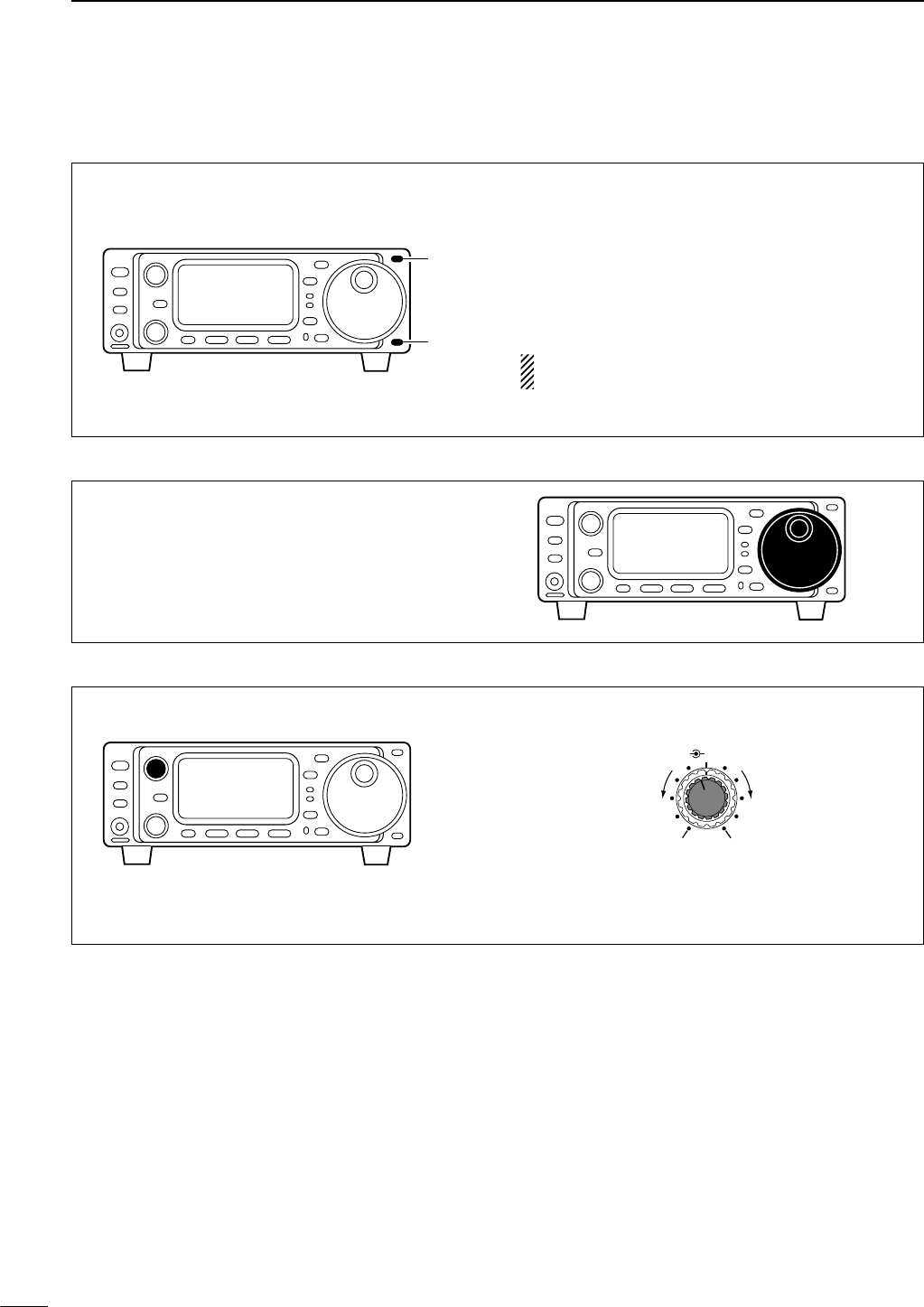
1. Before powering up your radio, you may want to
make sure the following controls are set in the fol-
lowing positions:
• [AF] : Commonly referred to as the vol-
ume: fully counter clockwise.
• [RF/SQL] : The control for the RF Gain and
Squelch circuits: 12 o’clock.
•[SHIFT] : Shifts the IF center frequency:
12 o’clock
2. Resetting the CPU: Although you have purchased
a brand new radio, some settings may be changed
from the factory defaults during the QC process. So
your radio can start from Factory Defaults resetting
the CPU is necessary. (Refer to p.17)
[POWER]
[Y]
[Z]
■Your first contact
Now you should have your IC-703 installed in your
shack, and like a kid on his birthday, you are probably
excited to get on the air. We would like to take you
through a few basic operation steps to make your first
“On The Air” an enjoyable experience.
DGetting started
Quick Reference
V
QUICK REFERENCE GUIDE
DJust listening
1. Select the desired band
3. Adjust audio output
On your IC-703, an easy way of changing bands is by
using the [(Y)BAND] or [(Z)BAND] located just right
corner on the front panel.
Push [(Y)BAND] or [(Z)BAND] to select the desired
band.
•Pushing [(Y)BAND] or [(Z)BAND] continuously scrolls
through the available bands.
•Say you want to go to 20 meters or 14 MHz; you
would push [(Y)BAND] or [(Z)BAND] several times
to select it. This will change the displayed operating
frequency to the 20-meter band.
NOTE: The band stacking register can also be
used to select bands. (Refer to p. 22)
[Y]
[Z]
Directly left of the [(Y)BAND]/[(Z)BAND] is the main
dial. This will allow you to dial in the frequency you
want to operate. You will notice the tuning speed [TS]
is 10 Hz resolution. Page 20 will instruct you on how
to set the tuning speed [TS] for 1 Hz resolution.
Adjust this control to a comfortable audio level.
AF RF/SQL
No audio output Max. audio output
Decreases Increases
2. Tune to the desired frequency
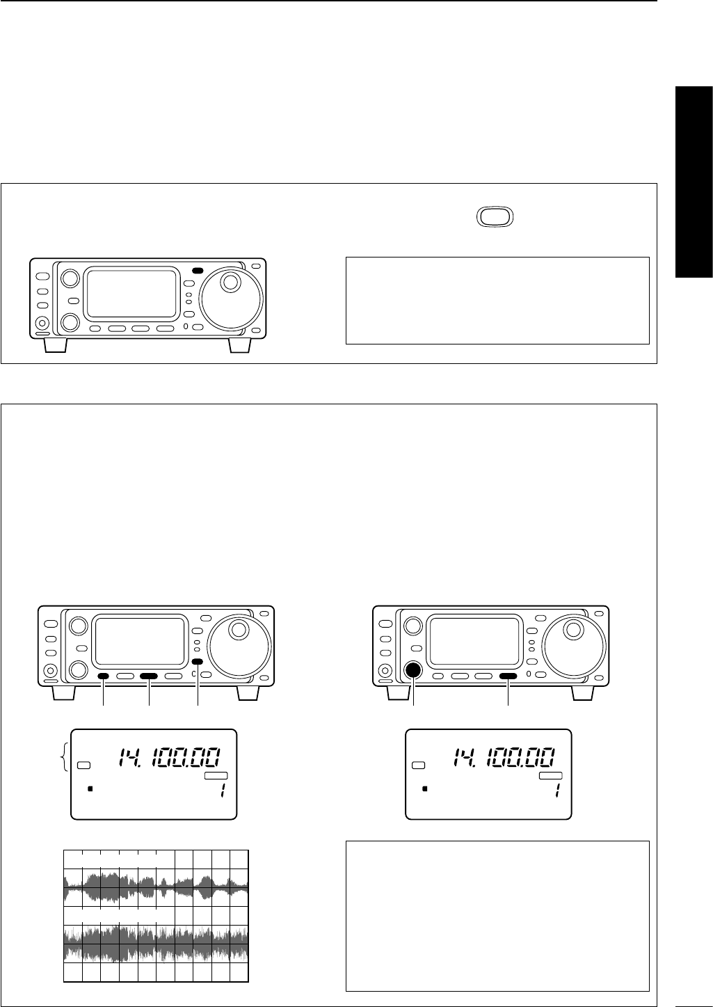
VI
QUICK REFERENCE GUIDE
DWhat are you hearing?
Stop and focus on what you are hearing. Do you hear
a lot of noise? Is the signal intelligible? Are you set up
for the right mode? How about the filters?
1. Verify mode
Your IC-703 has many features to reduce QRM and
QRN from the desired signal.
a. Noise Reduction: The noise reduction system on
your IC-703 is part of the DSP. This is used to re-
duce the hiss and QRM levels.
qSelect S4 (DSP menu).
•Push [DISPLAY] once or twice to select S.
•Push [MENU] one or more times to select S4.
wPush [(F-2)NR] to activate the noise reduction func-
tion.
• “DSP” and “NR” appear when the function is ON.
b. Adjusting the Noise Reduction: The noise re-
duction is completely variable on how much of the
DSP Noise Reduction is used.
qPush [(F-3)NRL] to indicate the noise reduction
level.
wRotate the [M-CH] control to set the noise reduc-
tion level.
ePush [(F-3)NRL] to exit the noise reduction level
set mode.
Hint!
How far you advance the NR control will determine
how much the noise can be effectively reduced. Ad-
justing the noise reduction level too high may cause
some distortion to occur on the received signal. The
noise reduction level should only be set as high as
is necessary. Use this setting, along with RF gain,
NB (noise blanker, if needed), and IF filters as well,
to minimize the effects of noise on the target signal.
CH
VFO A
P
O
S1
5
5379
20 40
10
60dB
USB
BLANK
S4 LEVEL 4 NRL
NR
DSP
[(F-3)][M-CH]
Noise reduction ON
Noise reduction OFF
CH
VFO A
P
O
S1
5
5379
20 40
10
60dB
USB
BLANK
S4 ANF NR NRL
NR
DSP
[(F-2)][MENU] [DISPLAY]
Appear
Although your IC-703 will automatically select USB or
LSB in the HF bands, it will not select any of the other
modes. You will need to select the proper mode
whether CW, RTTY, AM or FM.
Hint!
The Band Stacking Register will memorize the last
frequency used in the band, as well as the Mode,
Filter, Tuner and AGC settings. This makes band
hoping much easier.
MODE
2. Reducing interference (some functions may require an optional unit depending on version)
Quick Reference
VII
QUICK REFERENCE GUIDE
c. Automatic Notch: The automatic notch will track
up to heterodynes. This is helpful for eliminating
annoying transmitter “tune up” tones on any band,
and to minimize continuous tone “heterodynes” en-
countered on the 40 meter phone bands at night,
for example. Once selected an icon will appear
“ANF” on the display.
qSelect S4.
•Push [DISPLAY] once or twice to select S.
• Push [MENU] one or more times to select S4.
wPush [(F-1)ANF] to activate the automatic notch fil-
ter.
NOTE: Your IC-703 is equipped with an AGC cir-
cuit. This allows the DSP to filter out interfering sig-
nals and QRM, while also taking this interference
out of the AGC. Bottom line, this will either elimi-
nate or greatly reduce the pumping of the AGC
from the interfering signal.
Hint!
The Automatic Notch will not operate in the CW,
RTTY or SSB-D modes.
CH
VFO A
P
O
S1
5
5379
20 40
10
60dB
USB
BLANK
S4 ANF NR NRL
ANF
ANF
DSP
Appear
[(F-1)]
[DISPLAY][MENU]
d. Noise Blanker: The noise blanker function re-
duces pulse-type noise such as that generated by
automobile ignition systems. This function is not ef-
fective for FM modes or for non pulse-type noise.
qSelect M3.
•Push [DISPLAY] once or twice to select M.
• Push [MENU] one or more times to select M3.
wPush [(F-2)NB] to activate the noise blanker.
• “NB” appears when the function is ON.
e. Adjusting the Noise Blanker: The noise blanker
is completely variable on how much of the Noise
Blanker is used.
qPush [(F-2)NB] for 1 sec. to enter the noise blanker
level set mode.
wRotate the main dial to set the noise blanker level.
ePush [DISPLAY] to exit the noise blanker level set
mode.
Hint!
When using the noise blanker, received signals
may be distorted if the noise blanker level setting
has been too high.
USB
N1 NB LEVEL
[(F-2)] Main dial
[DISPLAY]
CH
VFO A
P
O
S1
5
5379
20 40
10
60dB
USB
BLANK
M3 FIL NB MET
NB
[(F-2)][MENU] [DISPLAY]
Appears
VIII
QUICK REFERENCE GUIDE
f. Filter:
One optional filter can be installed in the IC-703.
Narrow filters help reject interference from adjacent
signals and obtain good selectivity.
Wide filters provide improved audio for SSB opera-
tion when no interfering signals are present.
Narrow filters for AM/FM modes are standard.
FILTER PRESETTING:
After you install a filter (see p. 87 for installation), you
must specify the installed filter in initial set mode (item
“22 OPT. FIL” ; see p. 79).
FILTER ON/OFF:
qSelect M3.
•Push [DISPLAY] once or twice to select M.
• Push [MENU] one or more times to select M3.
wPush [(F-1)FIL] momentarily to select the narrow
filter; push for 1 sec. to select the wide filter.
•ãappears when the narrow filter is selected; çap-
pears when the wide filter is selected.
NOTE:
When selecting the narrow filter (or wide fil-
ter), the graphic passband is changed (see dia-
gram below).
CH
VFO A
P
O
S1
5
5379
20 40
10
60dB
USB
BLANK
M3 FIL NB MET
N W
[(F-1)]
[MENU] [DISPLAY]
Either these
appears when selected
Normal
operation
wide is
selected
narrow is
selected
We hope these pointers have been helpful. Now you
are ready for the “Ready to call CQ?”.
Quick Reference
IX
QUICK REFERENCE GUIDE
1. Setting up your Mic Gain
Microphone gain must be adjusted properly so that
your signal does not distort when transmitted.
qSelect SSB or another phone mode (AM or FM
mode).
w
Push [DISPLAY] for 1 sec. to select quick set mode.
ePush [MENU] one or more times to select “Q2
MIC GAIN.”
•The ALC meter is selected automatically when operat-
ing in SSB mode.
rWhile speaking into the microphone, rotate the
main dial to adjust the microphone gain so that the
ALC meter does not peak past the ALC zone.
•While transmitting at your normal voice level, the ALC
meter should read at about the middle of the ALC zone.
• Be sure the mic gain is in the range of 2 to 5.
tPush [DISPLAY] to exit quick set mode.
ALC
ALC zone
ALC
S1 5379
20 40 60dB
USB
Q2 MIC GAIN
[MENU] Main dial
[DISPLAY]
■Ready to call CQ?
BAND
BAND
MODE
TS
DISPLAY
LOCK
F 1 F 2 F 3
AF RF SQL
RIT
SHIFTM-CH
SUB
PHONES
TUNER
P.AMP AT T
Y
Z
POWER
MENU
TX
RX
[AF]: Max. CCW
[RF/SQL]: Center
[LOCK]: OFF
(indicator light out)
[POWER]: OFF
[SHIFT]: Center
[P.AMP/ATT]: OFF
(indicator lights out)
[TUNER]: OFF
(indicator lights out)
[RIT/SUB]: OFF
(indicator lights out)
CCW : counterclockwise
X
QUICK REFERENCE GUIDE
The IC-703 has a built-in, low distortion speech com-
pressor circuit. This circuit increases your average
talk power in SSB mode and is especially useful for
DX’ing when the receiving station is having difficulty
copying your signal.
qSelect USB or LSB mode.
wSelect the ALC meter.
• Push [DISPLAY] once or twice to select M.
•Push [MENU] one or more times to select M3, then push
[(F-3)MET] one or more times to select “ALC.”
eSelect M4.
•Push [MENU] one more time to select M4.
rPush [(F-2)COM] to turn the speech compressor
function ON.
• “COM” appears.
tPush [(F-2)COM] for 1 sec. to enter the compres-
sion level set mode (p. 54).
yRotate the main dial to set the speech compression
level.
NOTE: When the ALC meter peaks at light the ALC
zone, your transmitted voice may be distorted. Hint!
Voice patterns and audio characteristics vary with
each operator, therefore the Microphone gain,
speech compression settings will be different for
each operator. Actual on air experimenting is nec-
essary to get just the right sound. It’s best to test
and adjust your audio on the air, while someone
who knows what your real voice sounds like listens,
and provides and opinion on your audio quality.
ALC
ALC zone
ALC
S1 5379
20 40 60dB
USB
C1 COMP LEVEL
[MENU] [(F-2)]
[(F-3)]
Main dial[DISPLAY]
2. Speech compressor
Verify you have selected a clear frequency
and call out your CQ!
Quick Reference
1
1
PANEL DESCRIPTION
■Front panel
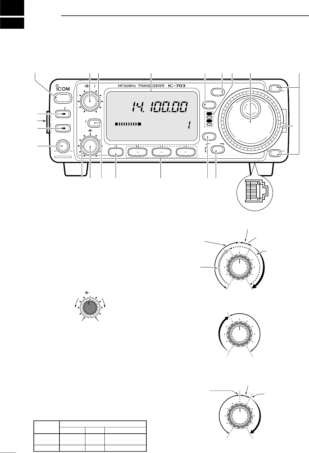
qPOWER SWITCH [POWER] (p. 17)
➥While transceiver’s power is OFF:
Push to turn power ON.
• Turn the DC power supply ON in advance.
➥While transceiver’s power is ON:
❍Push momentarily to indicate the connected
power supply voltage.
❍Push for 1 sec. to turn power OFF.
wAF GAIN CONTROL [AF] (inner control; p. 17)
Varies the audio output level from the speaker.
eRF GAIN CONTROL/SQUELCH CONTROL
[RF/SQL] (outer control; p. 24)
Adjusts the RF gain and squelch threshold level.
The squelch removes noise output from the speaker
(closed condition) when no signal is received.
•The squelch is particularly effective for FM. It is also
available for other modes.
•12 to 13 o’clock position is recommended for any setting
of the [RF/SQL] control.
•The control can be set as ‘Auto’ (RF gain control in SSB,
CW and RTTY; squelch control in AM and FM) or
squelch control (RF gain is fixed at maximum) in initial
set mode as follows. (p. 79)
• When setting as RF gain/squelch control
•When functioning as RF gain control
(Squelch is fixed open; SSB, CW, RTTY only)
•When functioning as squelch control
(RF gain is fixed at maximum.)
Squelch is
open.
S-meter
squelch
S-meter squelch
threshold
Noise squelch
threshold
(FM mode)
Shallow Deep
Noise squelch (FM mode)
Minimum RF gain
Adjustable
range
Maximum
RF gain
Recommended level
RF gain
adjustable
range
Maximum
RF gain
S-meter
squelch
Noise squelch (FM mode)
Squelch is
open.
MODE
SSB, CW
RTTY
AM, FM
AUTO
RF GAIN
SQL
SQL
SET MODE SETTING
SQL
SQL
RF GAIN + SQL
RF GAIN + SQL
RF GAIN + SQL
AF RF/SQL
No audio output Max. audio output
Decreases Increases
BAND
BAND
MODE
TS
DISPLAY
LOCK
F 1 F 2 F 3
AF RF SQL
RIT
SHIFTM-CH
SUB
PHONES
TUNER
P.AMP AT T
Y
Z
POWER
MENU
TX
RX
CH
VFO A
P
O
S1
5
5379
20 40
10
60dB
USB
M1 SPL A/B XFC
qwe
rtyio
!1
!2!3!4!5!6!7!8
!9
@0
@2
@1
!0
u
2
1
PANEL DESCRIPTION
rFUNCTION DISPLAY
Shows the operating frequency, dot matrix indica-
tions, selected memory channel, etc. See p. 9 for
details.
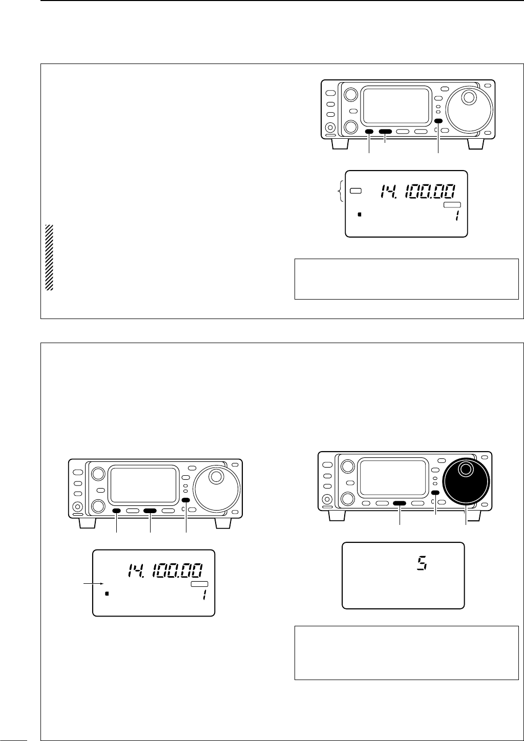
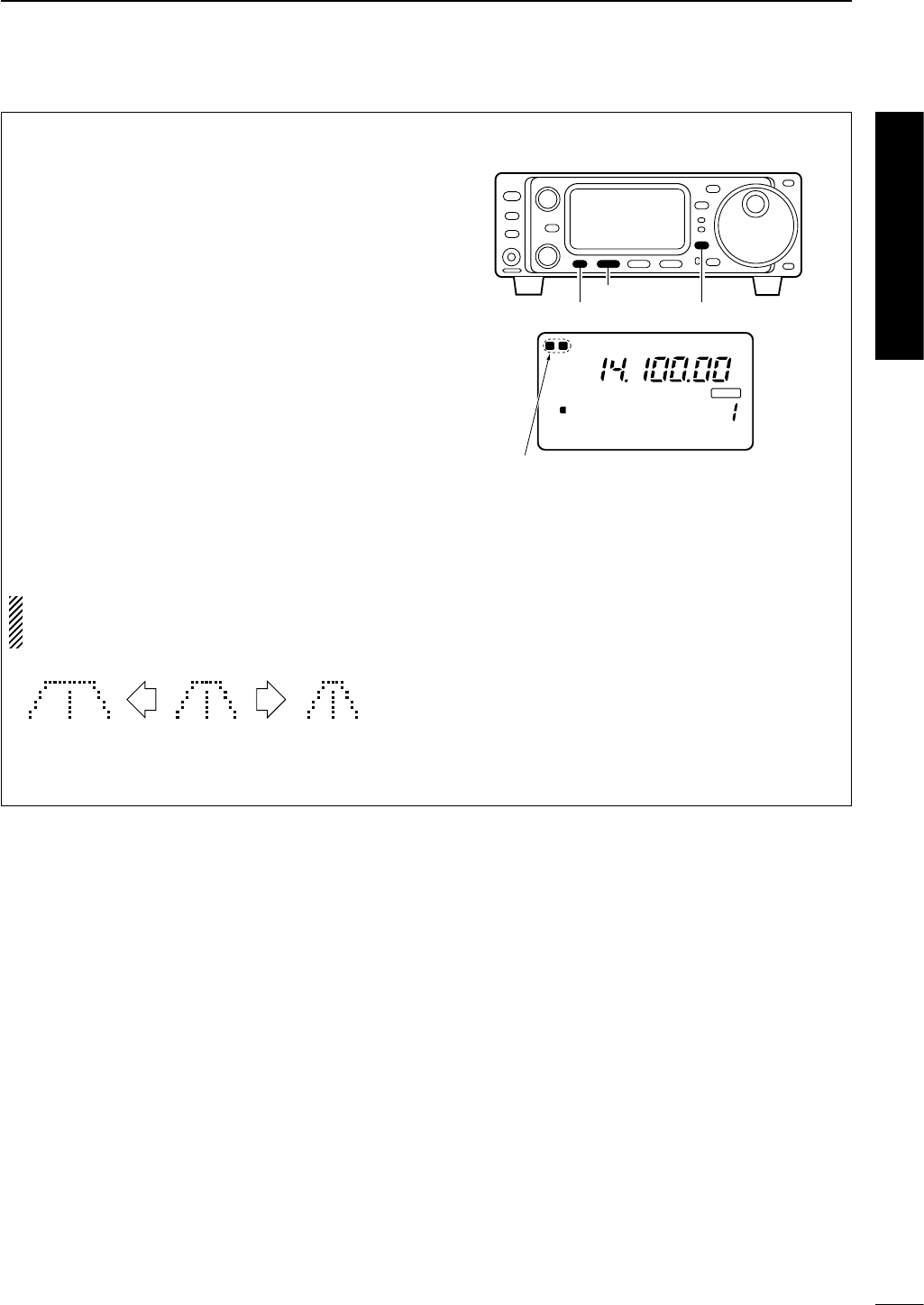
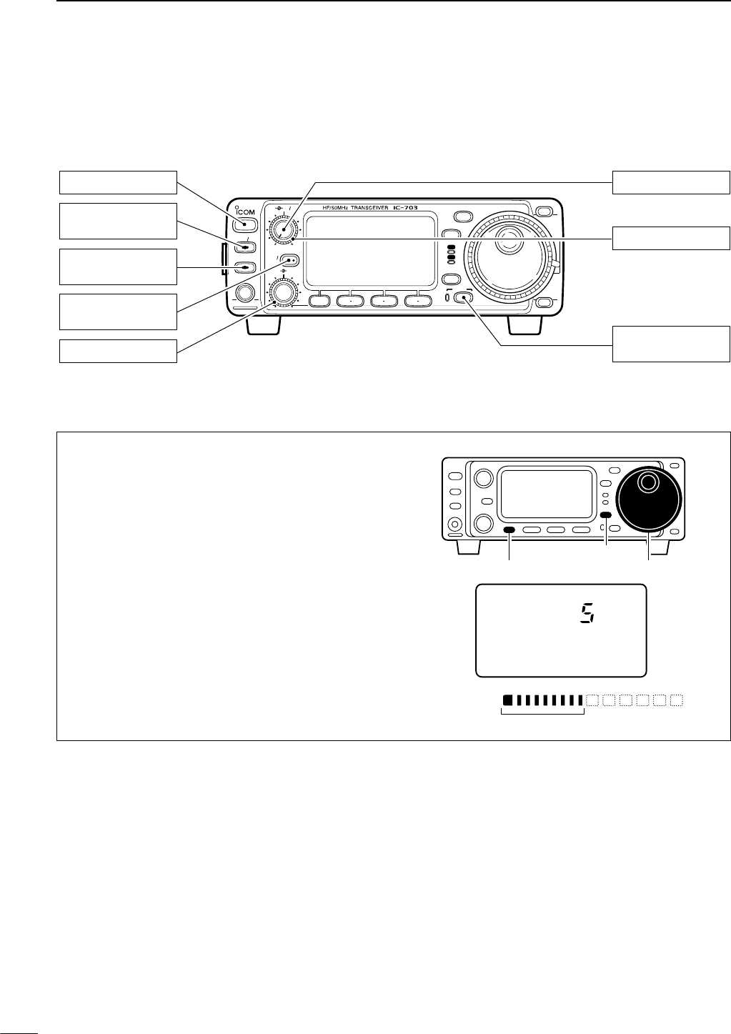
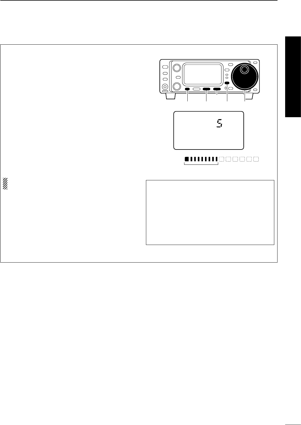
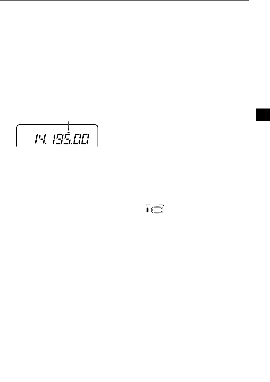
tTUNING STEP SWITCH [TS] (pgs. 19–21)
➥While in SSB/CW/RTTY modes, push momentar-
ily to turn the programmable tuning step ON and
OFF. While in FM/AM mode push momentarily to
toggle the programmable tuning step and 1 MHz
quick tuning step.
•While the programmable tuning step indicator is dis-
played, the frequency can be changed in programmed
kHz steps.
•0.01 (FM/AM mode only), 0.1, 1, 5, 9, 10, 12.5, 20, 25
and 100 kHz tuning steps are available.
•1 MHz quick tuning step are only available in FM and
AM modes.
➥While the programmable tuning step is OFF, turns
the 1 Hz step ON and OFF when pushed for 1
sec.
•1 and 10 Hz steps are only available in SSB, CW and
RTTY modes.
•1 Hz indication appears, and the frequency can be
changed in 1 Hz steps.
➥While the programmable tuning step is ON, en-
ters the tuning step selection mode when pushed
for 1 sec.
yMODE SWITCH [MODE] (p. 23)
➥Push momentarily to cycle through the operating
modes:
USB/LSB ➧CW ➧RTTY/SSB-D ➧FM/AM
➥Push for 1 sec. to toggle the following operating
modes:
USB ↔LSB
CW ↔Memory keyer mode
RTTY↔SSB-D (SSB data mode)
FM ↔AM
uRECEIVE/TRANSMIT INDICATORS [RX]/[TX]
➥[RX]: Lights green while receiving a signal and
when squelch is open.
➥[TX]: Lights red while transmitting.
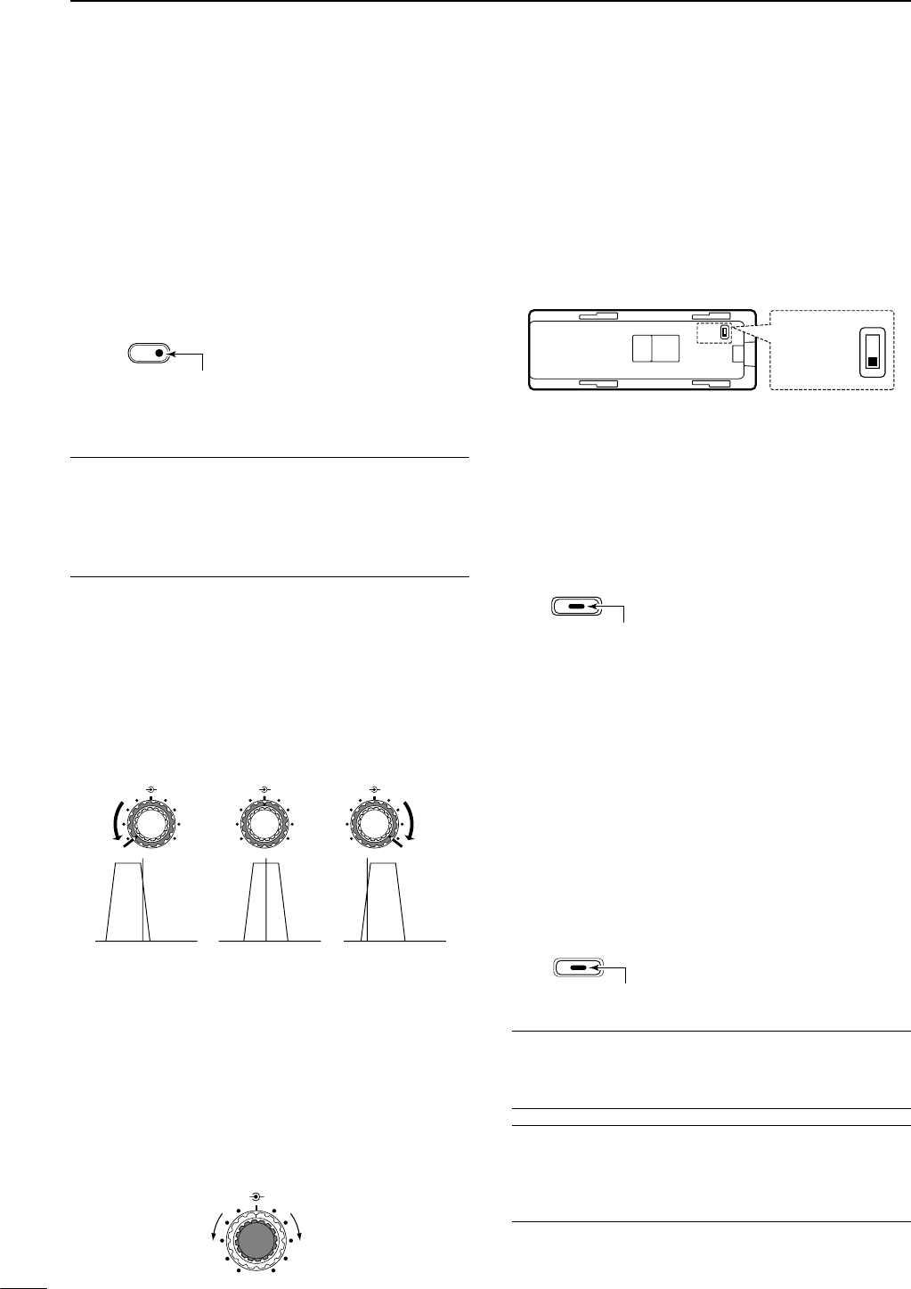
iMAIN DIAL
Changes the displayed frequency, sets the values
of selected initial set mode items, etc.
oUP/DOWN (BAND) SWITCHES [Y/Z(BAND)]
➥Push momentarily to select a band.
•Can also be used to advance or back the quick set
mode items, initial set mode items, etc.
➥Push and hold to scroll through the bands contin-
uously.
!0 MAIN DIAL TENSION LATCH
Selects the main dial tension.
• 2 positions are available.
!1 MICROPHONE CONNECTOR (p. 10)
Modular-type microphone connector—Accepts the
supplied microphone (HM-103).
•The optional OPC-589 can be used to connect an 8-pin
microphone such as the SM-8 or SM-20, if desired.
•A microphone connector is also available on the rear
panel. DO NOT connect 2 microphones simultaneously.
!2 LOCK SWITCH [LOCK]
➥Push momentarily to toggle the dial lock function
ON and OFF.
•The dial lock function electronically locks the main
dial.
➥When the optional UT-102
VOICE SYNTHESIZER
UNIT
is installed (p. 86), push for 1 sec. to have
the frequency, etc. announced.
•UT-102 operation can be adjusted in the initial set
mode (p. 82).
!3 DISPLAY SWITCH [DISPLAY] (p. 94)
➥Push momentarily to select one of the three menu
sets: M1 to M4,S1 to S4 and G1 to G4.
➥Push for 1 sec. to enter the quick set mode.
!4 MULTI-FUNCTION SWITCHES [F1] / [F2] / [F3]
➥
Push to select the function indicated in the dot ma-
trix display above these switches. (pgs. 4–6, 94)
• Functions vary depending on the menu set selected.
➥Push to edit a character for memory keyer pro-
gramming or memory name. (pgs. 35, 59)
!5 MENU SWITCH [MENU] (p. 94)
➥Push this switch one or more times to select
menus within a menu set (M,Sor G), or push to
advance through the quick set mode and initial
set mode displays.
➥Push for 1 sec. to jump between two different
function menu sets.
Lights while the lock
function is activated.
LOCK
Programmable tuning step indicator
USB
1
3
1PANEL DESCRIPTION
!6 RIT/SUB DIAL SWITCH [RIT/SUB] (pgs. 21, 47)
➥Push to toggle the RIT or SUB DIAL function ON
and OFF—initial set mode is used to select the
desired action*.
•Lights green when the SUB DIAL function is ON; lights
red when the RIT function is ON.
•Use the [M-CH] control to vary the RIT frequency or
SUB DIAL frequency (see below).
➥When the RIT function is ON, push for 1 sec. to
add or subtract the shifted frequency to the oper-
ating frequency.
*Even if RIT is selected in initial set mode, RIT cannot be se-
lected when operating AM or FM modes.
✔
What is the RIT function?
The RIT (Receiver Incremental Tuning) shifts the receive fre-
quency without shifting the transmit frequency.
This is useful for fine tuning stations calling you on an off-fre-
quency or when you prefer to listen to slightly different-
sounding voice characteristics, etc.
!7 SHIFT CONTROL [SHIFT] (outer control; p. 47)
Shifts the center frequency of the receiver’s IF pass-
band.
•Rotate the control clockwise to shift the center frequency
higher, or rotate the control counterclockwise to shift the
center frequency lower.
•When rotate the control, the IF passband is graphically
displayed and changes in accordance with the [SHIFT]
control.
!8 M-CH CONTROL [M-CH] (inner control)
➥When the RIT or SUB DIAL functions are OFF, ro-
tate to select a memory channel number (p. 56).
➥Shifts the receive frequency while the RIT func-
tion is ON in SSB, CW and RTTY modes (see
above or p. 47).
• RIT variable range is ± 9.99 kHz
➥Changes the operating frequency in the selected
tuning steps while the SUB DIAL function is ON
(p. 21).
!9 HEADPHONE JACK [PHONES] (p. 14)
Accepts headphones with 8–16 Ωimpedance.
•When headphones are connected, no receive audio
comes from the speaker.
•When the PHONES/SPEAKER switch on the back of the
front panel is set to the [SPEAKER] position, an external
speaker can be connected. This is convenient for mobile
or outdoor operation.
@0 TUNER SWITCH [TUNER] (pgs. 64–66)
➥Push momentarily to toggle the automatic an-
tenna tuner function ON and OFF (bypass).
•Lights red when the automatic antenna function is ON.
➥Push this switch for 1 sec. to manually tune the
antenna.
•When the tuner cannot tune the antenna, the tuning
circuit is bypassed automatically after 20 sec.
@1 FRONT PANEL LATCH (p. 12)
Pull away from the transceiver (towards yourself
when looking at the front of the transceiver) to de-
tach the front panel from the main body of the trans-
ceiver.
@2 PRE AMP/ATTENUATOR SWITCH [P.AMP/ATT]
(p. 46)
➥Push momentarily to turn the preamp ON or OFF.
➥Push for 1 sec. to turn the 20 dB attenuator ON;
push momentarily to turn the attenuator OFF.
•Lights green when the preamp is ON; lights red when the
20 dB attenuator is ON.
✔
What is the preamp?
The preamp amplifies received signals in the front end cir-
cuit to improve the S/N ratio and sensitivity. Turn ON ‘P.AMP’
when receiving weak signals.
✔
What is the attenuator?
The attenuator prevents a desired signal from distorting
when very strong signals are near the desired frequency, or
when very strong electric fields, such as from a broadcast-
ing station, are near your location.
P.AMP/ATT
Lights green while the preamp is activated;
lights red while the attenuator is activated.
TUNER
Lights while the automatic
tuning function is activated.
Back of the front panel
PHONES ∫
SPEAKER √PHONES ∫
SPEAKER √
M-CH SHIFT
Decreases Increases
M-CH M-CH M-CHSHIFT SHIFT SHIFT
Shifts low Center Shifts high
RIT/
SUB
Lights red while the RIT function is activated;
green while the SUB DIAL function is activated.
4
1
PANEL DESCRIPTION
■Multi-function switches
DM1 functions
SPLIT OPERATION (p. 30)
➥Push momentarily to toggle the split func-
tion ON and OFF. (p. 51)
•“ä”appears when the split function is ON.
➥Push for 1 sec. to turn the quick split func-
tion ON. (p. 52)
•The offset frequency must be programmed in
advance using initial set mode. (p. 80)
•The offset frequency is shifted from the dis-
played frequency.
•The quick split function can be turned OFF
using initial set mode. (p. 79)
VFO A/B SELECTION
➥Push momentarily to toggle VFO A and
VFO B in VFO mode. (p. 18)
➥Push momentarily to toggle the transmis-
sion VFO and reception VFO during split
operation. (p. 51)
➥Push momentarily to toggle the transmit
and receive frequencies (and modes) of
memory channels when the split function
is turned ON.
➥Push for 1 sec. to equalize the frequency
and operatingmode of the two VFO’s.
•The rear (undisplayed) frequency and oper-
ating mode are equalized to the front (dis-
played) VFO frequency and operating mode.
TRANSMIT FREQUENCY CHECK (p. 51)
Monitors the transmit frequency when
pushed and held.
•While pushing this switch, the transmit fre-
quency can be changed with the main dial.
DM2 functions
MEMORY WRITE (p. 57)
Push for 1 sec. to store the selected read-
out frequency and operating mode into
the displayed memory channel.
MEMORY CLEAR (p. 58)
Push for 1 sec. to clear the selected read-
out memory channel contents.
•“}” appears.
•This switch does not function in VFO mode.
VFO/MEMORY
➥Push momentarily to toggle between VFO
and memory modes. (p. 56)
➥Push for 1 sec. to transfer the frequency
and operating mode in the selected mem-
ory channel to a VFO. (p. 58)
DM3 functions
FILTER SELECTION (p. 49)
Push to toggle the narrow filter (or wide
filter—push for 1 sec.) ON and OFF.
•“ã”appears when the narrow filter is ON;
“ç” appears when the wide filter is ON.
•An optional filter installation and presetting in
initial set mode (p. 79) is necessary to use
the following:
CW/RTTY narrow: FL-52A or FL-53A
SSB narrow: FL-222
SSB wide: FL-257
NOISE BLANKER (p. 48)
➥Push momentarily to toggle the noise
blanker ON and OFF.
•“NB” appears when the noise blanker func-
tion is ON.
•The noise blanker does not function in FM
mode; “30 AM NB” item (p. 80) in initial set
mode must be set to ON for the noise
blanker to work in AM mode.
➥Push for 1 sec. to enter the noise blanker
level set mode.
•The noise blanker level can be set in noise
blanker level set mode (p. 46).
F-2
NB
F-1
FIL
MENU
M3
F-1
FIL
F-2
NB
F-3
MET
F-3
V/M
F-2
MCL
F-1
MW
MENU
M2
F-1
MW
F-2
MCL
F-3
V/M
F-3
XFC
F-2
A/B
F-1
SPL
MENU
M1
F-1
SPL
F-2
A/B XFC
F-3
1
5
1PANEL DESCRIPTION
METER SELECTION (p. 52)
Selects the type of meter displayed (dur-
ing transmit) in the function display.
•Power, ALC or SWR metering can be se-
lected.
•Only an S-meter is available for receive.
DM4 functions
DURING SSB/AM OPERATION:
DURING CW OPERATION:
DURING RTTY OPERATION:
DURING SSB-D OPERATION:
DURING FM OPERATION:
VOX FUNCTION (p. 53)
➥Push momentarily to toggle the VOX func-
tion ON and OFF.
•“VOX” appears when the VOX function is
ON.
➥Push for 1 sec. to enter the VOX set
mode.
•The VOX delay, VOX gain and ANTI-VOX
can be set in VOX set mode.
✔
What is the VOX function?
The VOX function (voice operated transmission) starts trans-
mission without pushing the PTT switch when you speak into
the microphone; then, automatically returns to receive when
you stop speaking.
SPEECH COMPRESSOR (p. 54)
➥Push momentarily to toggle the speech
compressor ON and OFF.
•“COM” appears when the speech compres-
sor is ON.
➥Push for 1 sec. to enter the compression
level set mode.
•The COMP gain can be set in compression
level set mode.
AGC (p. 48)
Push to change the time constant of the
AGC circuit.
•“F
AGC
” appears when the fast time constant
is selected.
1/4 FUNCTION
Push to toggle the 1/4 tuning function ON
and OFF.
•When the 1⁄4function is ON, a bar appears
under the 1⁄4indication and fine tuning can be
used.
KEYER SET MODE (p. 32)
Push for 1 sec. to enter the keyer set
mode.
•The break-in setting, break-in delay time, CW
pitch, CW paddle type and dot/dash ratio can
be set in the keyer set mode.
✔
What is the break-in function?
Full break-in (QSK) activates the receiver between transmit-
ted dots and dashes. This is useful when operating in nets,
or during DX pileups and during contests, when “fast ex-
changes” are common.
RTTY TONE SET MODE (p. 40)
➥Push for 1 sec. to enter the RTTY tone set
mode.
•The RTTY tone frequency, RTTY shift fre-
quency and RTTY keying polarity can be set
in RTTY tone set mode.
FM TONE OPERATION
➥Push momentarily to select the subaudi-
ble tone encoder for repeater use, tone
squelch function and OFF. (pgs. 43–45)
•“T” appears when the repeater tone function
is ON. (pgs. 43, 45)
•“TSQL” appears when the tone squelch func-
tion is ON. (p. 43)
➥Push for 1 sec. to enter the FM tone set
mode. (p. 44)
•The repeater tone frequency, tone squelch
frequency can be set in FM tone set mode.
F-2
TON
F-2
TON
F-2
KEY
F-1
1/4
F-3
AGC
F-2
COM
F-1
VOX
MENU
M4
F-1
VOX
F-2
TON
F-3
MENU
M4
F-1
1/4
F-2 F-3
AGC
MENU
M4
F-1
1/4 TON
F-2 F-3
AGC
MENU
M4
F-1 F-2
KEY1/4
F-3
AGC
MENU
M4
F-1
VOX
F-2
COM
F-3
AGC
F-3
MET
6
1
PANEL DESCRIPTION
DS1 functions
MEMORY WRITE (p. 57)
Push for 1 sec. to store the selected
readout frequency and operating mode
into the displayed memory channel.
MEMO PAD WRITE (p. 60)
Push to store the the selected readout
frequency and operating mode into a
memo pad.
MEMO PAD READ (p. 60)
Push to call up a memo pad.
DS2 functions
DURING VFO MODE:
DURING MEMORY MODE:
SCAN (pgs. 61–63)
Push to start or stop the scan function.
PRIORITY WATCH (p. 63)
Push to start or stop the priority watch.
VFO/MEMORY
➥Push momentarily to toggle between VFO
and memory modes. (p. 56)
➥Push for 1 sec. to transfer the frequency
and operating mode in the selected mem-
ory channel to a VFO. (p. 58)
SELECT SCAN (p. 61)
Push to toggle the select setting ON and
OFF for the selected memory channel.
DS3 functions
QUICK BAND CHANGE FUNCTION (p. 22)
This item provides access to the band stacking regis-
ter. By default the 7, 14 and 21 MHz bands are dis-
played. Push [F-1], [F-2] or [F-3] for 1 sec. to select a
new band if desired.
•A mode is memorized along with the frequency for each
band.
DS4 functions
(UT-106 is required for some version)
AUTOMATIC NOTCH FILTER (p. 50)
This function automatically attenuates
beat tones, tuning signals, etc., even if
they are moving.
NOISE REDUCTION (p. 50)
This function reduces noise components
and picks out desired signals which are
buried in the noise.
NOISE REDUCTION LEVEL DISPLAY (p. 50)
This switch displays the noise reduction
level when pushed.
F-3
NRL
F-2
NR
F-1
ANF
MENU
S4
F-1
ANF
F-2
NR
F-3
NRL
MENU
S3
F-1
7
F-2
14
F-3
21
F-2
SEL
F-3
V/M
F-2
PRI
F-1
SCN
MENU
S2
F-1
SCN
F-2
SEL
F-3
V/M
MENU
S2
F-1
SCN
F-2
PRI
F-3
V/M
F-3
MPR
F-2
MPW
F-1
MW
MENU
S1
F-1
MW
F-2
MPW
F-3
MPR
1
7
1PANEL DESCRIPTION
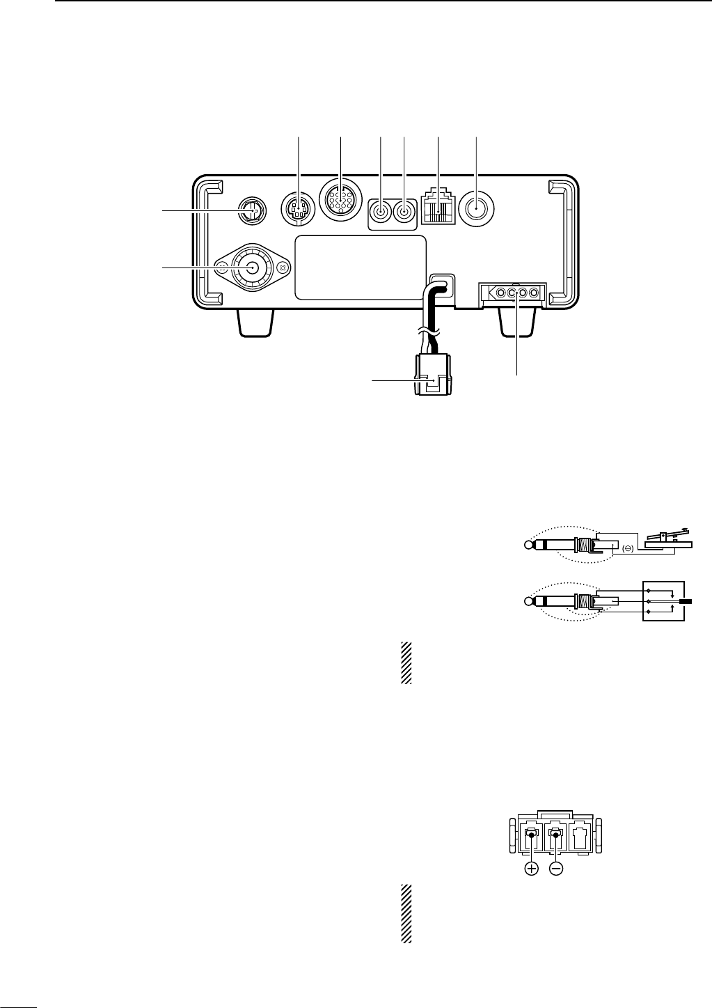
■Rear panel
qANTENNA CONNECTOR [ANT] (p. 13)
Accepts a 50 Ωantenna with a PL-259 connector.
wGROUND TERMINAL [GND] (p. 11)
Connect this terminal to a ground to prevent electri-
cal shocks, TVI, BCI and other problems.
eDATA SOCKET [DATA] (pgs. 8, 14)
6-pin min DIN socket to connect a TNC (Terminal
Node Controller), etc. for packet operation.
•See page at right for socket information.
rACCESSORY SOCKET [ACC] (pgs. 8, 14)
Enables connection to external equipment such as a
TNC for data communications, a linear amplifier or
an automatic antenna selector/tuner, etc.
•See page at right for socket information.
tEXTERNAL SPEAKER JACK [EXT SP] (p. 14)
Accepts a 4–8 Ωspeaker.
y
CI-V REMOTE CONTROL JACK [REMOTE] (p. 71)
➥Designed for use with a personal computer for re-
mote control of the transceiver functions.
➥Used for transceiver operation with another Icom
CI-V transceiver or receiver.
uMICROPHONE CONNECTOR [MIC] (p. 13)
Accepts the supplied microphone (connected in par-
allel with the front panel’s [MIC] connector).
•See p. 2 for microphone notes.
•See p. 10 for microphone connector information.
iELECTRONIC KEYER JACK [KEY] (p. 28)
Accepts a paddle to activate the internal electronic
keyer.
•Selection between the internal electronic keyer and
straight key operation can be made in keyer set mode.
(p. 32)
If you use an external electronic keyer, make sure
the voltage retained by the keyer is less than 0.4 V
when the key is ON.
oTUNER CONTROL SOCKET [TUNER] (p. 14)
Accepts the control cable from an optional AH-4
HF
/50
MH
z
AUTOMATIC ANTENNA TUNER
.
!0 DC POWER SOCKET [DC13.8V] (p. 15)
Accepts 9.0–15.87 V DC through the supplied DC
power cable.
NOTE: DO NOT use a cigarette lighter socket as a
power source when operating in a vehicle. The plug
may cause voltage drops and ignition noise may be
superimposed onto transmit or receive audio.
When connecting
a straight key
When connecting
a paddle
(dot)
(com)
(dash)
(⊕)
w
q
r
e t y u i
o
!0
8
1
PANEL DESCRIPTION
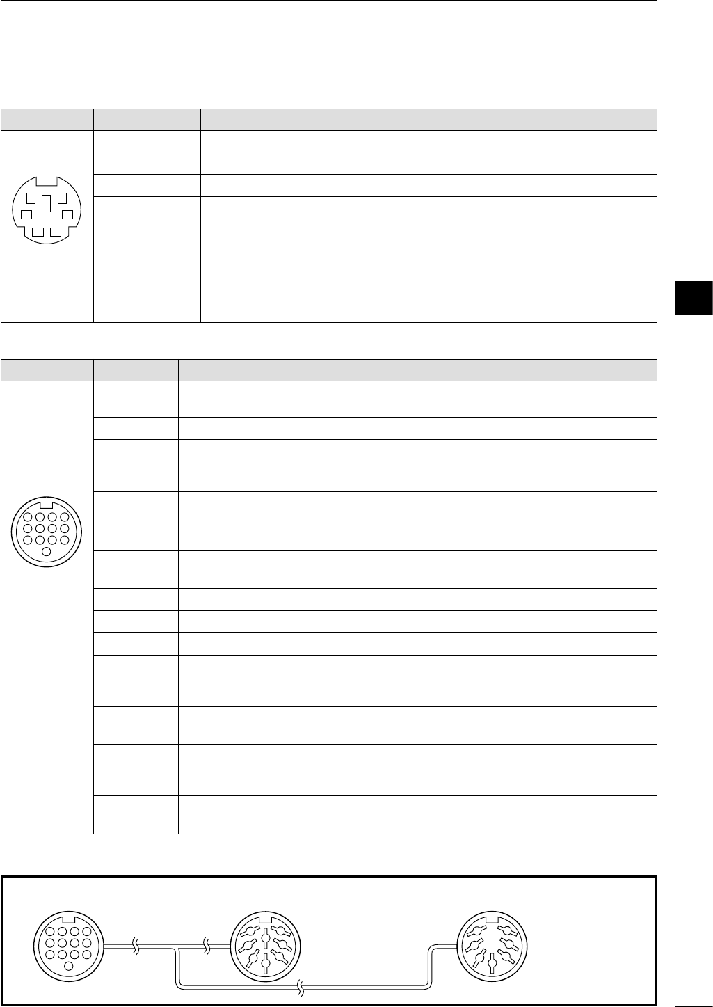
DDATA socket
DACC socket
ACC
PIN No.
NAME DESCRIPTION SPECIFICATIONS
1234
8765
9
101112
13
Rear panel view
qbrown igray
wred owhite
eorange !0 black
ryellow !1 pink
tgreen !2 light
blue
yblue
upurple !3 light
green
1 8 V Regulated 8 V output. Output voltage : 8 V ±0.3 V
Output current : Less than 10 mA
2 GND Connects to ground. ———
Input/output pin. (HF/50 MHz only) Ground level : –0.5 V to 0.8 V
3
HSEND
Goes to ground when transmitting. Output current : Less than 20 mA
When grounded, transmits. Input current (Tx) : Less than 200 mA
4 BDT Data line for the optional AT-180. ———
5 BAND Band voltage output. Output voltage : 0 to 8.0 V
(Varies with amateur band)
6 ALC ALC voltage input. Control voltage : –4 V to 0 V
Input impedance : More than 10 kΩ
7 NC ——— ———
8 13.8 V 13.8 V output when power is ON. Output current : Max. 1 A
9 TKEY Key line for the optional AT-180. ———
“High” level : More than 2.4 V
10 FSKK Controls RTTY keying “Low” level : Less than 0.6 V
Output current : Less than 2 mA
11 MOD Modulator input. Input impedance : 10 kΩ
Connects to a modulator. Input level : Approx. 100 mV rms
AF detector output. Output impedance : 4.7 kΩ
12 AF Fixed, regardless of [AF] position in Output level : 100–300 mV rms
default settings.
13 SQLS Squelch output. SQL open : Less than 0.3 V/5 mA
Goes to ground when squelch opens.
SQL closed : More than 6.0 V/100 µA
DATA
PIN No.
NAME DESCRIPTION
12
34
56
Rear panel view
1 DATA IN Input terminal for data transmit. (1200 bps: AFSK/9600 bps: G3RUH, GMSK)
2 GND Common ground for DATA IN, DATA OUT and AF OUT.
3 PTT P PTT terminal for packet operation. Connect ground to transmit data.
4 DATA OUT Data out terminal for 9600 bps operation only.
5 AF OUT Data out terminal for 1200 bps operation only.
Squelch out terminal. Becomes ground level when the transceiver receives a signal
which opens the squelch.
6SQ •To avoid unnecessary TNC transmission, connect squelch to the TNC to inhibit trans-
mission when receiving signals.
• Keep audio output at a normal level, otherwise a “SQ
”
signal will not be output.
Color refers to the cable strands of the supplied cable.
ACC 1 ACC 2
q FSKK t AF
w GND y SQLS
e HSEND u 13.8 V
r MOD i ALC
q 8 V t ALC
w GND y VSEND
e HSEND u 13.8 V
r BAND
1234
88
765
9
101112
13
1
2
3
4
76
5
1
2
3
4
76
5
Connect to ACC socket
• When connecting the ACC conversion cable (OPC-599)
1
9
1PANEL DESCRIPTION
■Function display
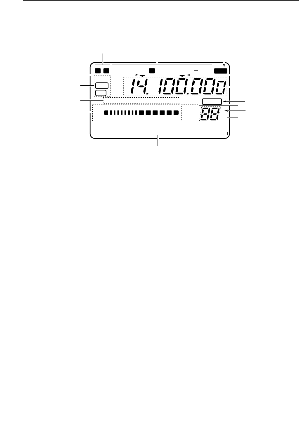
qNARROW/WIDE FILTER INDICATORS
➥“ã” appears when selecting AM narrow or FM
narrow modes.
➥When installing an optional narrow filter, narrow
mode can be selected in CW, RTTY and SSB
modes.
•When the SSB wide filter is installed, “ç” appears
during wide mode selection.
wMODE INDICATORS
Show the selected operating mode.
•“å” appears when CW reverse or RTTY reverse mode is
selected.
eSPLIT INDICATOR
Appears during split operation.
rPROGRAMMABLE/1 MHz TUNING STEP
INDICATORS
➥ra appears when the programmable tuning step
is selected.
➥rb appears when the 1 MHz quick tuning step is
selected.
tFREQUENCY READOUT
Shows the operating frequency.
yBLANK MEMORY INDICATOR
Appears when the displayed memory channel is not
programmed (blank channel).
• This indicator appears both in VFO and memory modes.
uVFO/MEMORY INDICATORS
➥VFO A or B appears when VFO mode is selected;
MEMO appears when memory mode is selected.
iSELECT MEMORY CHANNEL INDICATOR
Appears when the selected memory channel is set
as a select memory channel.
oMEMORY CHANNEL READOUT
Shows the selected memory channel.
!0 DOT MATRIX INDICATORS
These alphanumeric readouts show a variety of in-
formation such as current functions of the “F” keys
[F1] to [F3], memory channel names, set mode
items, etc. See p. 94 for an overview of these indi-
cators.
!1 METER READOUTS
➥Shows receiving signal strength while receiving.
➥Shows one of transmit power meter, ALC or SWR
meter while transmitting.
!2 FUNCTION INDICATORS
➥“NB” appears when the noise blanker is activated.
➥“VOX” appears when the VOX function is se-
lected.
➥“F-BK” appears when full break-in operation is se-
lected and only “BK” appears when semi break-
in operation is selected.
➥“COM” appears when the speech compressor is
activated.
➥“FAGC” appears when the fast AGC function is se-
lected.
!3 DSP INDICATORS
Appear when the (optional*) DSP unit UT-106 is (in-
stalled and) activated.
* UT-106 DSP unit is optional for some version.
N W R
LSB
NB VOX F-BK COM F
CH
VFO A
VFO B
MEMO
AGC
ALC
SWR P
O
S1
1 1.5 2 3 5
5379
20 40
10
60dB
USB CW R
TT
Y
AM FM TSQL
SPL
S
∞
NR
ANF
BLANK
DSP
qw
t
r
e
y
i
!0
!1
!2
!3
u
o
rb
M1 SPL A/B XFC
a
10
1
PANEL DESCRIPTION
• MICROPHONE CONNECTOR
■Microphone (HM-103)
qUP/DOWN SWITCHES [UP]/[DN]
Change the operating frequency.
•Push and hold to change the frequency continuously.
•Tuning step is 50 Hz when no TS indicator appears.
wLOCK SWITCH [LOCK]
Locks the [UP]/[DN] switches.
ePTT SWITCH [PTT]
Push and hold to transmit; release to receive.
DN UP
LOCK
OFF ON
q
w
e
TECHNICAL INFORMATION
PIN NO. FUNCTION DESCRIPTION
1+8 V DC output Max. 10 mA
2Frequency up Ground
Frequency down Ground through 470 Ω
8Squelch open “LOW” level
Squelch closed “HIGH” level
r PTT
y Microphone input
w Frequency up/down
u GND
q +8 V DC output
i Squelch switch
t GND (Microphone ground)
e AF output
Rear panel view
12345678
• HM-103 SCHEMATIC DIAGRAM
4700p
4700p
10µ0.33µ+
+
MICROPHONE
MIC
ELEMENT
2k
2.2k
470
DOWN
LOCK UP
PTT RECEIVE
TRANSMIT
MICROPHONE
CABLE
MICROPHONE PLUG
12345678
CAUTION:DO NOT short pin 1 to ground as
this can damage the internal 8 V regulator.
1
2
11
INSTALLATION AND CONNECTIONS
■Unpacking
After unpacking, immediately report any damage to the
delivering carrier or dealer. Keep the shipping cartons.
For a description and a diagram of accessory equip-
ment included with the IC-703, see ‘Supplied acces-
sories’ on p. ii of this manual.
■Selecting a location
Select a location for the transceiver that allows ade-
quate air circulation, free from extreme heat, cold, or
vibrations, and away from TV sets, TV antenna ele-
ments, radios and other electromagnetic sources.
The base of the transceiver has an adjustable stand
for desktop use. Set the stand to one of two angles de-
pending on your operating conditions. (see description
at right page)
■Grounding
To prevent electrical shock, television interference
(TVI), broadcast interference (BCI) and other prob-
lems, ground the transceiver through the GROUND
terminal on the rear panel.
For best results, connect a heavy gauge wire or strap
to a long earth-sunk copper rod. Make the distance be-
tween the [GND] terminal and ground as short as pos-
sible.
RWARNING: NEVER connect the [GND] ter-
minal to a gas or electric pipe, since the connection
could cause an explosion or electric shock.
■Antenna connection
For radio communications, the antenna is of critical im-
portance, along with output power and sensitivity. Se-
lect antenna(s), such as a well-matched 50 Ωantenna,
and feedline. 1.5:1 or better of Voltage Standing Wave
Ratio (VSWR) is recommended for your desired band.
Of course, the transmission line should be a coaxial
cable.
CAUTION: Protect your transceiver from lightning
by using a lightning arrestor.
ANTENNA SWR
Each antenna is tuned for a specified frequency
range and SWR may be increased out-of-range.
When the SWR is higher than approx. 2.0 : 1, the
transceiver’s power drops to protect the final transis-
tors. In this case, an antenna tuner is useful to match
the transceiver and antenna. Low SWR allows full
power for transmitting even when using the antenna
tuner. The IC-703 has an SWR meter to monitor the
antenna SWR continuously.
30 mm
10 mm (soft solder)
10 mm
1–2 mm
solder solder
Soft
solder
Coupling ring
PL-259 CONNECTOR INSTALLATION EXAMPLE
q
e
r
w
Slide the coupling ring
down. Strip the cable
jacket and soft solder.
Slide the connector
body on and solder it.
Screw the coupling
ring onto the connector
body.
Strip the cable as
shown at left. Soft
solder the center con-
ductor.
2
12
INSTALLATION AND CONNECTIONS
To raise the stand:
With the transceiver upside down, pull the stand to-
wards the rear panel and then upwards, as illus-
trated below.
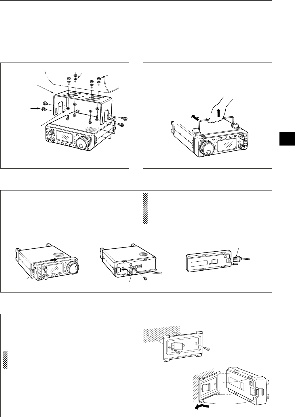
■Installation
DSingle body mounting DStand
Nut
Spring washer
Flat washer
*CAUTION: Non-supplied screws (longer than 8 mm)
may damage the internal units.
MB-62
(optional)
Supplied with
the MB-62*
Pull back
then up
DFront panel separation
DFront panel mounting
qWhile pulling the panel release button towards you,
slide the front panel to the right (fig. 1).
wAttach the optional OPC-581 to the main body and
tighten the supplied screw as in fig. 2.
eAttach the other end of the OPC-581 to the de-
tached front panel as in fig. 3.
CAUTION: NEVER detach/attach the front panel
when connecting the DC power supply (or battery).
Make sure the disconnecting DC power cable from
the [13.8 V] receptacle on the transceiver rear
panel.
qAttach the MB-63 to a flat surface using the two
supplied screws (fig. 1).
wFix the detached front panel to the MB-63 as illus-
trated in fig. 2.
BE CAREFUL of the orientation of the MB-63, oth-
erwise, the front panel may become attached in the
opposite direction.
fig. 1 fig. 2 fig. 3
Latch Separation cable
Separation cable
fig. 1
fig. 2
2
13
2INSTALLATION AND CONNECTIONS
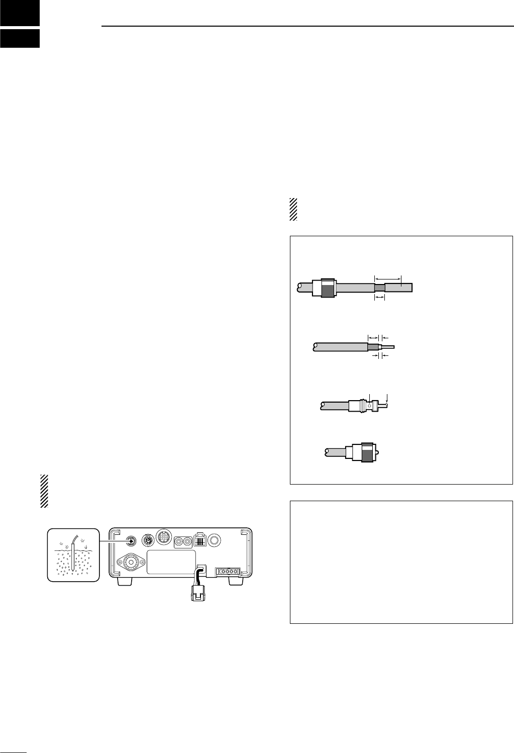
■Required connections
BAND
BAND
MODE
TS
DISPLAY
LOCK
F 1 F 2 F 3
AF RF SQL
RIT
SHIFTM-CH
SUB
PHONES
TUNER
P.AMP ATT
Y
Z
POWER
MENU
TX
RX
MICROPHONE (p. 10)
HF/50 MHz ANTENNA
GROUND (p. 11)
HM-103
CW KEY (p. 28)
Use the heaviest gauge wire or
strap available and make the
connection as short as possible.
Grounding prevents electrical
shocks, TVI and other problems.
Connects to DC 9.0–15.8 V
power supply. See p. 15 for
details.
14
2
INSTALLATION AND CONNECTIONS
■Advanced connections
BAND
BAND
MODE
TS
DISPLAY
LOCK
F 1 F 2 F 3
AF RF SQL
RIT
SHIFTM-CH
SUB
PHONES
TUNER
P.AMP ATT
Y
Z
POWER
MENU
TX
RX
OPC-589 (p. 92)
DESKTOP (p. 91)
MICROPHONE
Selectable with the [PHONE/SPEAKER] switch
on the back of the front panel.
SPEAKER
ACC SOCKET (p. 8)
DATA SOCKET (p. 8)
6-pin mini DIN socket to connect to a
TNC, etc. for packet operation.
AH-4 (p. 16)
AH-2b
EXTERNAL
SPEAKER (p. 91)
HEADPHONES
SP-7/SP-10
SM-20
or
REMOTE (p. 71)
Used for computer control
and transceive operation.
2
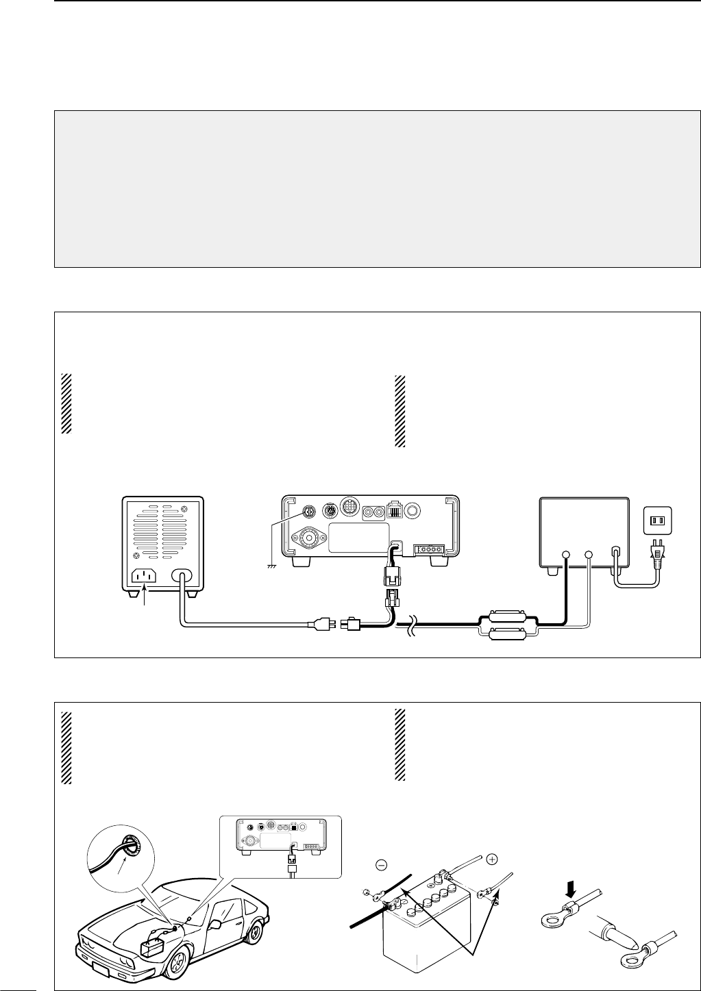
Use a 13.8 V DC power supply with at least 3 A ca-
pacity. when operating IC-703 with AC power. Refer
to the diagram below for connection.
CAUTION:
Before connecting the DC power cable, check the
following important items. Make sure:
• The [POWER] switch is OFF.
•Output voltage of the power source is 9.0–15.8 V
when you use a non-Icom power supply.
•DC power cable polarity is correct.
Red: positive (+) terminal,
Black: negative (–) terminal
■DC Power supply connections
15
2INSTALLATION AND CONNECTIONS
■Battery connections
■DC Power voltage
Depending on the applied voltage from the connected
power supply, a boarder voltage of 11.0 V is set as the
point where the IC-703 switches between normal op-
erating mode (over 11.0 V), and battery operating
mode (under 11.0 V: power save mode).
However when the connected voltage decreases from
13.8 V to 11.0V, the IC-703 switches from normal
mode to battery mode. Conversely the IC-703
switches back to normal mode from battery mode
when the voltage reaches 11.5 V. This 0.5 V voltage
difference prevents irregular switching between nor-
mal mode and battery mode, caused by the voltage
drop which are current capacity, receiving or transmit-
ting.
When 11.3 V voltage is applied, the IC-703 may acti-
vate the battery operating mode depending on the
current capacity of the power supply.
AC cable
AC
outlet
A DC power
supply*
*13.8 V; at least 3.0 A
continuous
Black
_ Red
+
CONNECTING A DC POWER SUPPLYCONNECTING PS-125 DC POWER SUPPLY
PS-125
DC power cable
Ground
4 A fuses
Transceiver
to DC power
receptacle Supplied
OPC-1229
Optional
OPC-1248
Connect to an AC
outlet using the
supplied AC cable.
•RWARNING NEVER connect to a battery
without supplied DC fuse, otherwise a fire hazard
occur.
•NEVER connect the transceiver directly to a
24 V battery.
•DO NOT use the cigarette lighter socket for power
connections. (See p. 7 for details)
•Attach a rubber grommet when passing the DC
power cable through a metal plate to prevent a
short circuit.
Grommet
CONNECTING A VEHICLE BATTERY
Note: Use terminals for
the cable connections.
Crimp
Solder
Supplied
DC power cable
red
black
12 V
battery
16
2
INSTALLATION AND CONNECTIONS
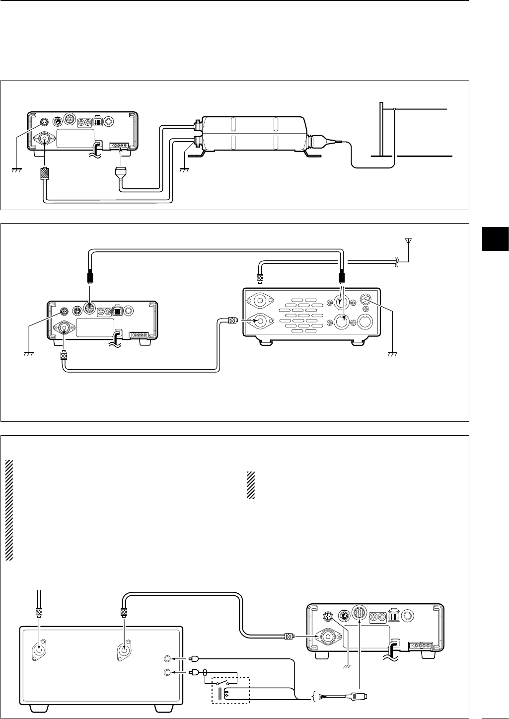
■External antenna tuners and linear amplifier
GroundGround
Long wire or optional AH-2b
AH-4
ANT
IC-703
Coaxial cable
(from the AH-4)
CONNECTING THE AH-4
IC-703
Ground Ground
AT-180
CONNECTING THE AT-180
HF
to 6 m
antenna
[TRANSCEIVER]
[ANT]
[ANT]
[ACC] [ACC]
ACC cable supplied with the AT-180
Coaxial cable supplied
with the AT-180
one of two
connectors
Note:
Turn the IC-703’s power OFF when connecting
the AT-180, otherwise, the CPU may malfunction
and the AT-180 may not function properly.
CONNECTING A NON-ICOM LINEAR AMPLIFIER
RWARNING:
•
Set the transceiver output power and linear ampli-
fier ALC output level referring to the linear amplifier
instruction manual. Be sure the linear amplifier key-
ing circuit control voltage is compatible with the IC-
703, before connecting to HSEND line (ACC cable).
•The ALC input level must be in the range 0 V to
–4 V, and the transceiver does not accept positive
voltage. Non-matched ALC and RF power settings
could cause a fire or damage the linear amplifier.
•The specifications for the SEND relay are 16 V
DC 0.5 A. If this level is exceeded, a large external
relay must be used.
HSEND
(Orange)
ALC (Blue)
13.8V (Gray)
Ground
Relay
RF INRF OUT
ALC
SEND
ANT
ACC cable
ACC
IC-703
50 Ω coaxial cable
To an
antenna
2
3
17
BASIC OPERATION
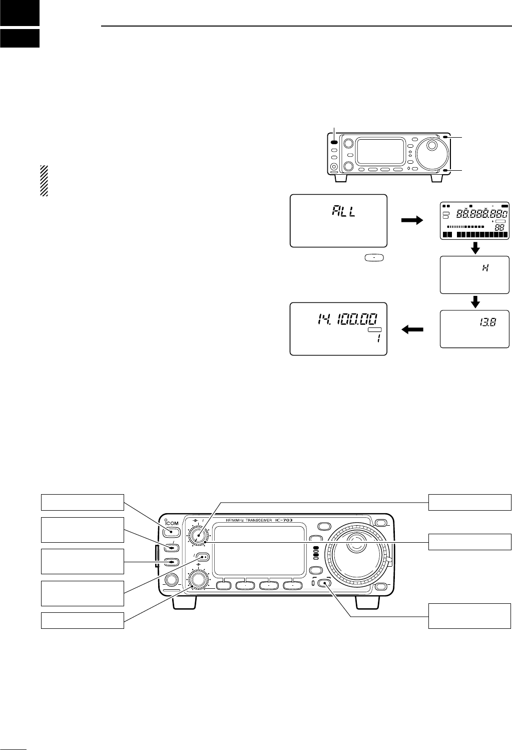
■When first applying power (CPU resetting)
Before first applying power, make sure all connections
required for your system are complete by referring to
Chapter 2. Then, reset the transceiver using the fol-
lowing procedure.
Resetting CLEARS all programmed contents in
memory channels and returns all initial set mode and
quick set mode contents to their default values.
qMake sure the transceiver power is OFF.
wWhile pushing [Y] and [Z], push [POWER] to turn
power ON.
•“CLEAR ? OK” appears as shown at right.
eThen push [F-3] for 1 sec to start resetting.
• The internal CPU is reset.
•The display changes to ‘All indication,’ ‘RF power,’ ‘Power
supply voltage’ and ‘Initial frequency and Mode’ as shown
at right.
DM1 display selection
If you can’t figure out how to return to the M1 display:
While pushing [MENU], turn power ON.
■Initial settings
After resetting the transceiver, set controls and
switches as shown in the diagram below.
[POWER]
[Y]
[Z]
CLEAR ? OK
F 3
Push [F-3]
for 1 sec.
N W R
LSB
NB VOX F-BK COM F
CH
VFO A
DUP
VFO B
MEMO
AGC
ALC
SWR P
O
S1
11.52 35
5379
20 40
10
60dB
USB CW R
TT
Y
AM WFM TSQL
SPL
S
∞
NR
ANF
BLANK
DSP
CH
VFO A
P
O
S1
5
5379
20 40
10
60dB
USB
BLANK
M1 SPL A/B XFC DC SUPPLY
RF POWER
The transceiver’s
initial frequency and mode
BAND
BAND
MODE
TS
DISPLAY
LOCK
F 1 F 2 F 3
AF RF SQL
RIT
SHIFTM-CH
SUB
PHONES
TUNER
P.AMP AT T
Y
Z
POWER
MENU
TX
RX
[AF]: Max. CCW
[RF/SQL]: Center
[LOCK]: OFF
(indicator light out)
[POWER]: OFF
[SHIFT]: Center
[P.AMP/ATT]: OFF
(indicator lights out)
[TUNER]: OFF
(indicator lights out)
[RIT/SUB]: OFF
(indicator lights out)
CCW : counterclockwise
Turn power ON, then check the display. If any of the
following indicators appear, turn them OFF as follows:
•Tuning step indicators,
Z
, (SSB, CW or RTTY):
Push [TS].
•MHz tuning step indicator,
Z
, (FM or AM):
Push [TS].
• 1 Hz frequency readout (SSB, CW or RTTY):
Push and hold [TS].
• Memory mode indicator, MEMO:
Use [(F-3)V/M] in the M2 display (p. 75).
• Split indicator, ä:
Use [(F-1)SPL] in the M1 display (p. 75).
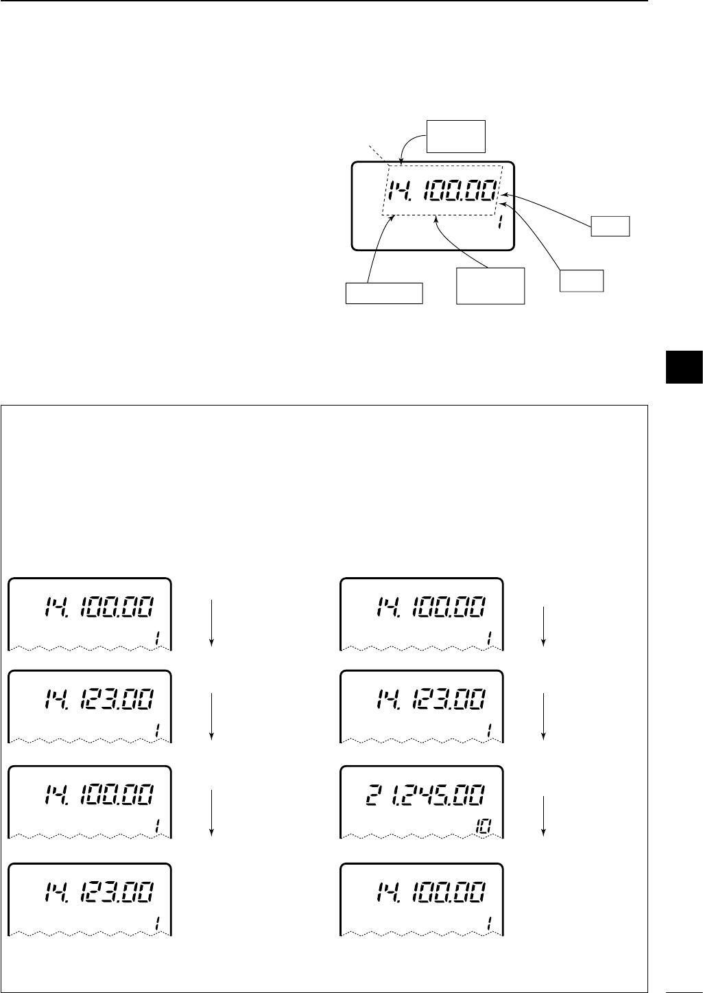
18
3
BASIC OPERATION
■VFO description
VFO is an abbreviation of Variable Frequency Oscilla-
tor, and traditionally refers to an oscillator. The IC-703’s
VFO can store a frequency and an operating mode.
You can call up a desired frequency to a VFO with the
memo pad-read switch (p. 60) or with the memory
transfer switch (p. 58). You can also change the fre-
quency with the main dial and select an operating
mode with the [MODE] switch or call up previously ac-
cessed frequency and modes with the band stacking
register (p. 22).
The IC-703 has two VFOs, specially suited for split fre-
quency operation. The VFOs are called VFO A and
VFO B. You can use the desired VFO to call up a fre-
quency and operating mode for operation.
CH
VFO A
USB
M1 SPL A/B XFC
VFO MODE
SWITCH
MEMORY
CHANNEL
DIAL
MEMO PAD
28.025 MHz 7.001 MHz
21.295 MHz
BAND
Select
Change
Transfer
Transfer
Transfer
DThe differences between VFO and memory mode
VFO MODE
Each VFO shows a frequency and operating mode. If
the frequency or operating mode is changed, the VFO
automatically memorizes the new frequency or oper-
ating mode.
When the VFO is selected from another VFO or
memory mode, the last-used frequency and operat-
ing mode for that VFO appear.
[EXAMPLE]
MEMORY MODE (pgs. 56–60)
Each memory channel shows a frequency and oper-
ating mode like a VFO. Even if the frequency or mode
is changed, the memory channel does not memorize
the new frequency or operating mode.
When a memory channel is selected from another
memory channel or VFO mode, the memorized fre-
quency and operating mode appear.
[EXAMPLE]
CH
VFO A
USB
CH
VFO A
USB
VFO is selected.
The frequency is changed.
MEMO
CH
VFO A
USB VFO is selected again.
Changed frequency (14.123 MHz) appears. Changed frequency (14.123 MHz) does not appear and
memorised frequency (14.100 MHz) appears instead.
CH
USB Memory mode is selected.
CH
USB
CH
USB
Memory channel 1 is
selected.
The frequency is changed.
MEMO
MEMO
MEMO
MEMO
CH
USB Memory channel 1 is
selected again.
CH
USB Another memory channel
is selected.
3
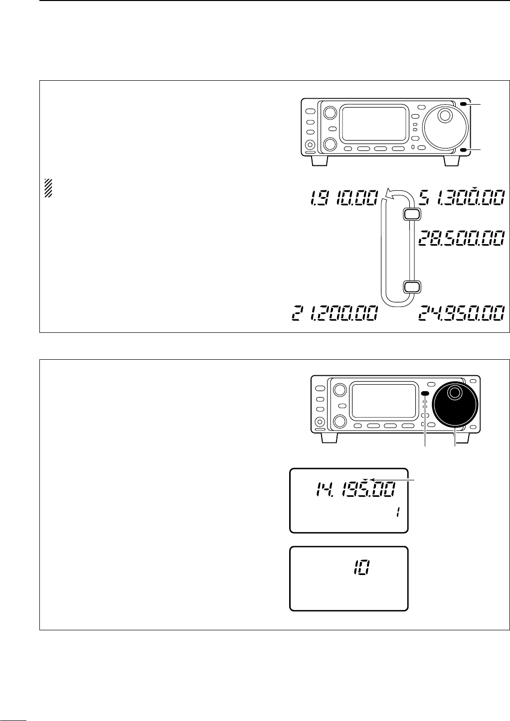
19
3BASIC OPERATION
• Programmable tuning steps
Programmable tuning steps are available to suit your
operating requirements.
These tuning steps are:
• Independently selectable for each mode
•Selectable from 0.01 (FM/AM only), 0.1, 1, 5, 9, 10,
12.5, 20, 25 and 100 kHz
qPush [TS] one or more times until the programma-
ble tuning step indicator “
Z
” appears above the 1
kHz digit.
•Rotating the main dial changes the frequency according
to the set tuning step.
wPush [TS] for 1 sec. while the programmable tuning
step indicator appears to enter the tuning step se-
lection mode.
•“Rotate DIAL” appears.
eRotate the main dial to set the desired tuning step.
•Change the mode and select tuning steps for other
modes, if desired.
rPush [TS] to exit the tuning step selection mode.
tRotate the main dial to change the frequency ac-
cording to the set tuning step.
• Band selection
All HF ham bands, the 50 MHz band and a general
coverage receiver band are included in the IC-703.
Push [(Y)BAND]/[(Z)BAND] to select the desired
band.
•Pushing [(Y)BAND]/[(Z)BAND] continuously scrolls
through the available bands.
The band stacking register can also be used to se-
lect bands. Refer to p. 22.
USB
FM
USB
USB
LSB
Z
Z
■Frequency setting
Programmable tuning
step indicator
10 kHz tuning step is
selected for USB
operation.
CH
VFO A
P
O
S1
5
53792040
10
60dB
USB
USB
M1 A/B XFC
DIAL
SPL
Rotate
[Y]
[Z]
[TS] Main dial
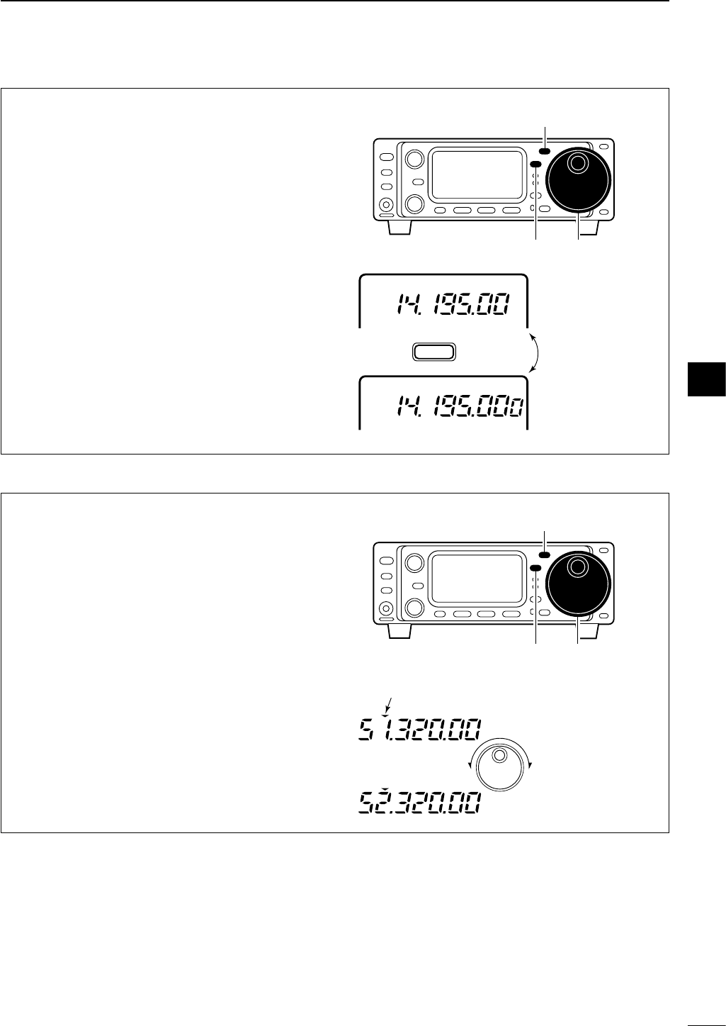
20
3
BASIC OPERATION
• 1 Hz and 10 Hz tuning steps
When neither the quick tuning step or programmable
tuning step “
Z
” appear, rotating the main dial
changes the frequency in increments of 1 or 10 Hz.
These tuning steps are only available in SSB, CW
and RTTY modes.
qSelect SSB, CW or RTTY mode if necessary.
wPush [TS] for 1 sec. to toggle between the 1 Hz
and 10 Hz step settings.
•When the 1 Hz step is selected, the 1 Hz digit appears
in the frequency indication; when the 10 Hz step is se-
lected, the 1 Hz digit disappears from the frequency in-
dication.
•Rotating the main dial changes the frequency 1 Hz or
10Hz tuning step.
Rotating the main dial
changes the frequency
in 10 Hz steps.
Rotating the main dial
changes the frequency
in 1 Hz steps.
TS
Push for 1 sec.
VFO A
USB
VFO A
USB
[TS]
[MODE]
Main dial
• 1 MHz quick tuning step
The quick tuning step function allows you to change
the frequency in 1 MHz steps when rotating the main
dial. This function is only available in FM and AM
modes.
qSelect FM or AM mode if necessary.
wPush [TS] momentarily to toggle between the 1
MHz tuning step and the programmable tuning
step.
•“
Z
” appears above the 1 MHz indicator when the 1
MHz tuning step is selected.
•Rotating the main dial changes the frequency 1 MHz or
set tuning step.
Quick tuning step
indicator
FM
FM
Rotating the main dial
changes the frequency
in 1 MHz steps.
[TS]
[MODE]
Main dial
3
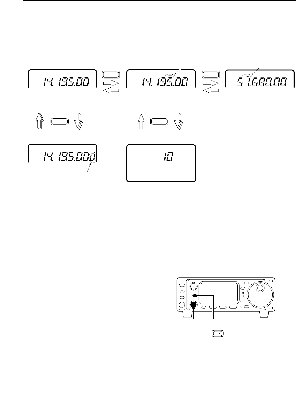
21
3BASIC OPERATION
• Sub dial function
The sub dial function allows you to change the oper-
ating frequency using the [M-CH] control. This gives
you more control in tuning since the [M-CH] knob is
detented—each click changes the frequency accord-
ing to the set tuning step. This function is always
available in FM and AM modes. However, in SSB,
CW and RTTY modes, the initial set mode item “21
SUB DIAL” (p.61), must be set to “FrEq.”
qPush [RIT/SUB] to turn the sub dial function ON.
•The [SUB] indicator lights green; if it lights red, the RIT
function is activated—sub dial function must be set in
initial set mode in this case.
wRotate [M-CH] to change the operating frequency
according to the set tuning step.
ePush [RIT/SUB] again to turn the function OFF.
• The [SUB] indicator turns off.
[RIT/SUB][M-CH]
RIT/
SUB Indicator lights green
while the sub dial
function is activated.
• [TS] switch flow chart
SSB/CW/RTTY modes Any mode FM/AM modes
TS
USB
10 Hz tuning
USB
1 Hz tuning
momentarily momentarily
momentarily
1 sec.1 sec.
1 sec.
TS
TSTS
1 MHz tuning
USB
Programmable step tuning
(100 Hz –100 kHz)
Selectable for each mode.
USB
Rotate DIAL
FM
Appears
AppearsAppears
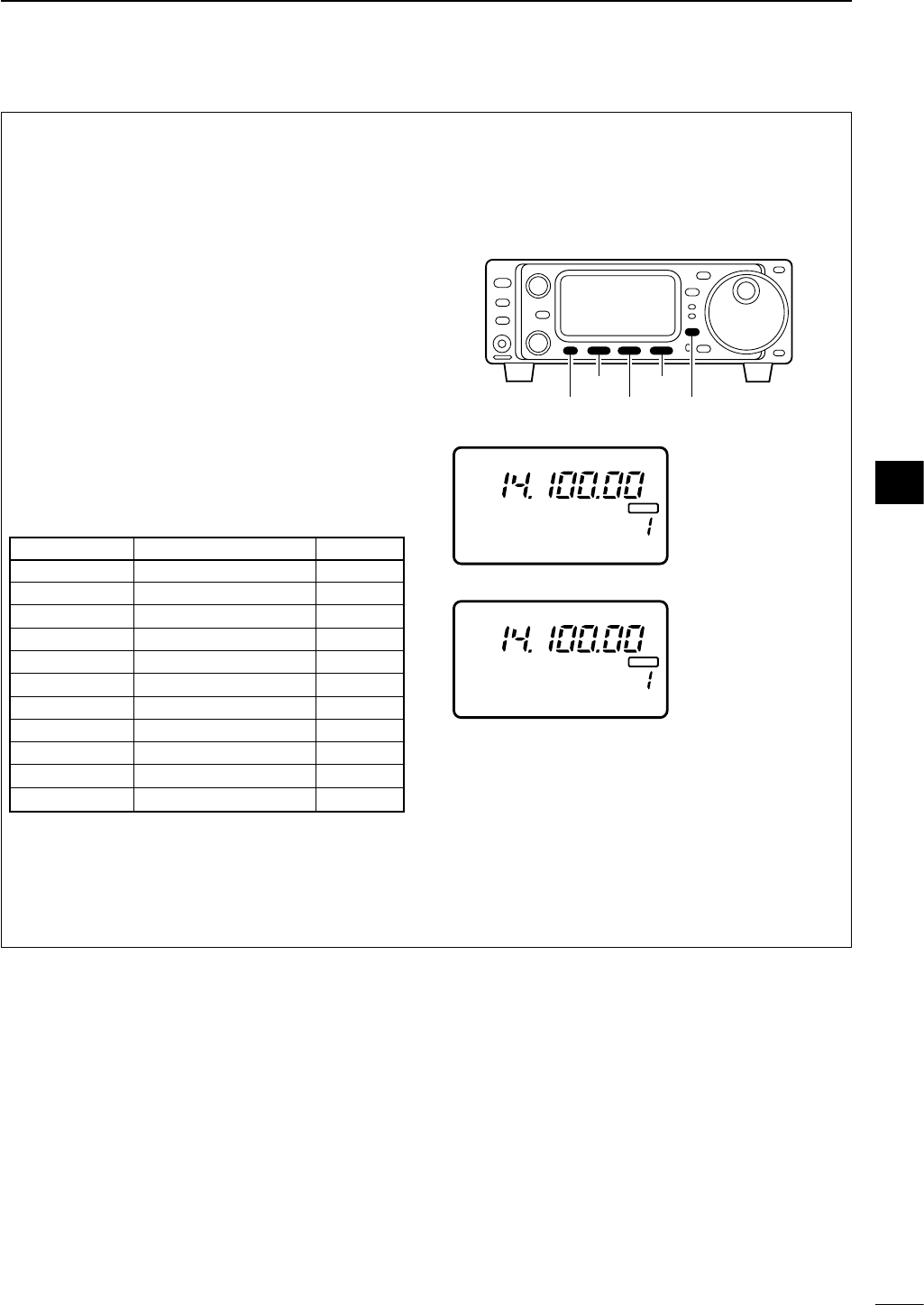
22
3
BASIC OPERATION
• Quick band change function
The quick band change function automatically stores
the last frequency and mode used for each band in a
band stacking register. This is convenient for contest
operation, etc. The tables below show the quick band
change default settings for each band.
qSelect S3.
• Push [DISPLAY] once or twice to select S.
• Push [MENU] one or more times to select S3.
wPush [F-1], [F-2] or [F-3] to select a band stacking
register.
•The default settings for [F-1], [F-2], [F-3] are 7, 14, 21
MHz bands, respectively.
eTo change the settings for [F-1], [F-2] or [F-3] from
their defaults, push [F-1], [F-2] or [F-3] for 1 sec.
one or more times to until the desired band ap-
pears in the display above the corresponding
switch.
•The last-used frequency and mode for the selected
band are displayed.
*11.83000 MHz for Italy version (#10, #20).
*250 MHz band is not available for some version.
*3General refers to the general coverage receiver (GEN in
the display) and the range varies according to version.
BLANK
CH
VFO A
S1 5379204060dB
USB
S3 7GEN 21
P
O
510
Display shows [F-2]
has been changed
from its default of the
14 MHz band to the
general receiver band.
BLANK
CH
VFO A
S1 5379204060dB
USB
S3 7 14 21
P
O
510
Display shows the
default bands for the
quick band change
function.
[DISPLAY][F-2][MENU]
[F-3][F-1]
BAND FREQUENCY MODE
1.9 MHz 1.90000 MHz*1CW
3.5 MHz 3.55000 MHz LSB
7 MHz 7.05000 MHz LSB
10 MHz 10.12000 MHz CW
14 MHz 14.10000 MHz USB
18 MHz 18.10000 MHz USB
21 MHz 21.20000 MHz USB
24 MHz 24.95000 MHz USB
28 MHz 28.50000 MHz USB
50 MHz*250.10000 MHz USB
General*315.00000 MHz USB
3
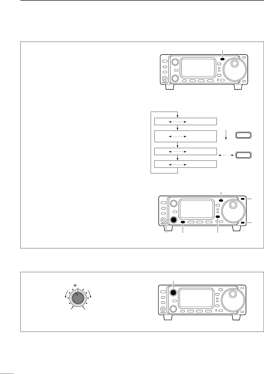
■Volume setting
23
3BASIC OPERATION
■Operating mode selection
The following modes are available in the IC-703:
SSB (LSB/USB), CW, CW-å(CW reverse), RTTY
and åRTTY (RTTY reverse), FM, AM.
•SSB (LSB/USB), CW, RTTY, SSB-D, FM and
AM modes selection
To select the desired mode of operation, push
[MODE] one or more times, then push [MODE] for 1
sec., if necessary. See the diagram at right for the
order of selection.
• The selected mode is indicated in the function display.
•CW-å(CW reverse) mode selection
qWhen selecting CW mode, push [DISPLAY] for 1
sec. to enter quick set mode.
wPush [MENU] one or more times to select item “Q3
CW REV” during CW mode.
•[Y]/[Z] or [M-CH] can also be used.
eRotate the main dial to select CW reverse.
rPush [DISPLAY] to exit quick set mode.
•“CW-å” appears.
•åRTTY (RTTY reverse) mode selection
qWhen selecting RTTY mode, push [DISPLAY] for 1
sec. to enter quick set mode.
wPush [MENU] one or more times to select item “Q2
RTTY REV” during RTTY mode.
•[Y]/[Z] or [M-CH] can also be used.
eRotate the main dial to select RTTY reverse.
rPush [DISPLAY] to exit quick set mode.
•“åRTTY” appears.
Note:If a desired mode cannot be selected, it may be
hidden using initial set mode (p. 76).
[DISPLAY]
[MODE]
[MENU][M-CH]
[Y]
[Z]
OPERATING MODE SELECTION
MODE
Push
momentarily
Memory keyer
set mode
MODE
Push
for 1 sec.
USB LSB
FM AM
SSB-D
CW
RTTY
[MODE]
Rotate [AF] control to output a suitable audio level.
[AF]
AF RF/SQL
No audio output Max. audio output
Decreases Increases
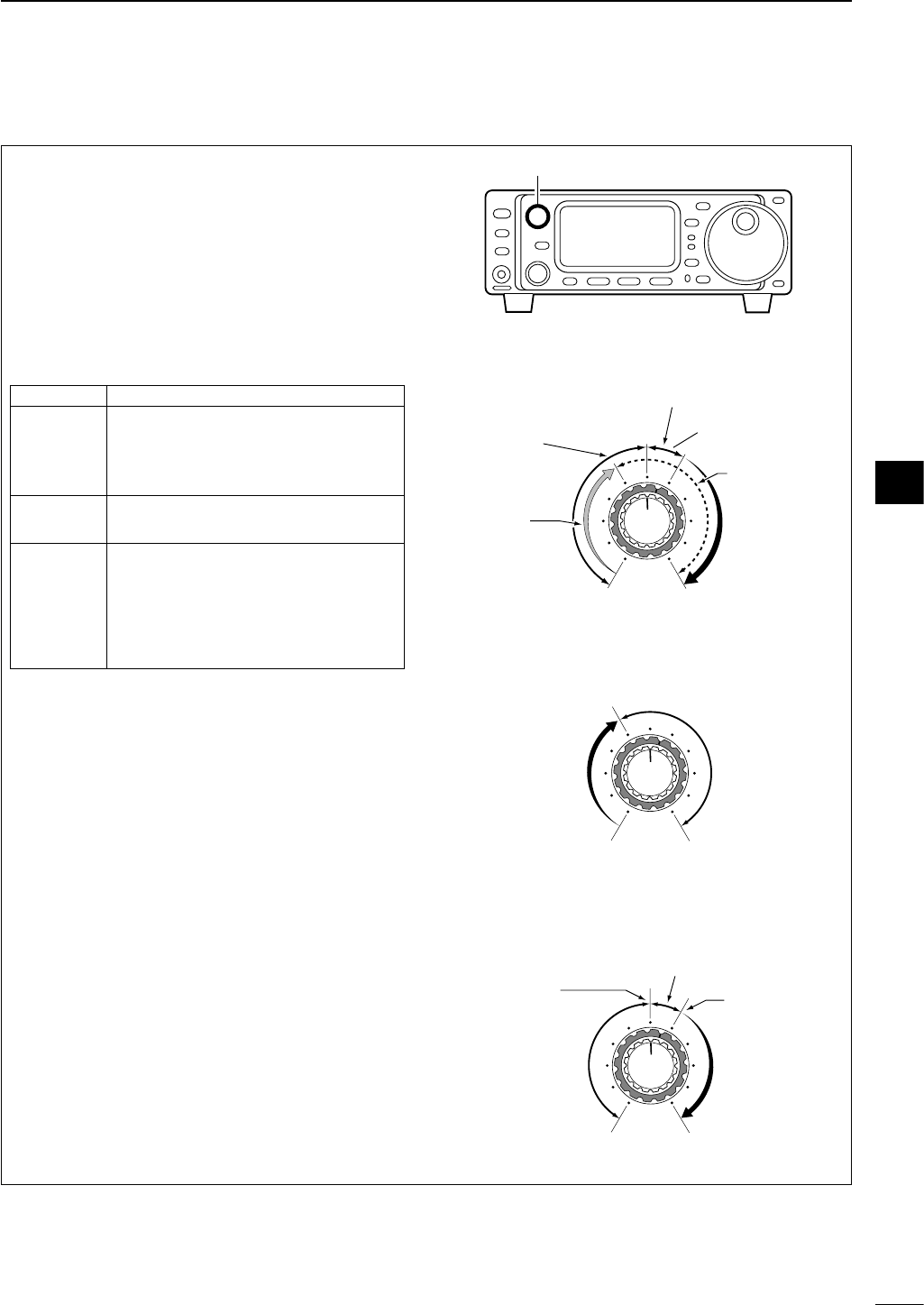
24
3
BASIC OPERATION
■Squelch and receive (RF) sensitivity
Adjusts the RF gain and squelch threshold level. The
squelch removes noise output from the speaker
(closed position) when no signal is received.
• The squelch is particularly effective for FM mode. It is also
available for other modes.
•The control can be set as the RF gain control only
(squelch is fixed open) or squelch control (RF gain is fixed
at maximum) in initial set mode (p. 79). See below right.
• The 11 to 12 o’clock position is recommended for any set-
ting of the [RF/SQL] control.
Adjusting RF gain (Receive sensitivity)
Normally, [RF/SQL] is set to the 11 o’clock position.
Rotate [RF/SQL] to the 11 o’clock position for maxi-
mum sensitivity.
• Rotating counterclockwise from the maximum position re-
duces sensitivity.
• The S-meter indicates receive sensitivity.
Adjusting squelch (Removing non-signal noise)
Rotate [RF/SQL] clockwise when receiving no signal,
until the noise just disappears.
• [RX] indicator light goes out.
• Rotating [RF/SQL] past the threshold point invokes the S-
meter squelch— this allows you to set a minimum signal
level needed to open the squelch.
• When setting as RF gain/squelch control
•When functioning as RF gain control (Squelch is
fixed open; SSB, CW, RTTY only)
•When functioning as squelch control (RF gain is
fixed at maximum)
Squelch is
open.
S-meter
squelch
S-meter squelch
threshold
Noise squelch
threshold
(FM mode)
Shallow Deep
Noise squelch (FM mode)
Minimum RF gain
Adjustable
range
Maximum
RF gain
Recommended level
RF gain
adjustable
range
Maximum
RF gain
S-meter
squelch
Noise squelch (FM mode)
Squelch is
open.
[RF/SQL]
SET MODE OPERATION
RF+SQL
Can be used in all modes.
(default)
Functions as noise squelch or S-meter
squelch in AM and FM modes; S-
meter squelch only in other modes.
SQL Operates as a squelch control.
• RF gain is fixed at maximum sensitivity.
Operates as an RF gain control in
SSB, CW and RTTY modes.
AUTO •Squelch is fixed open.
Operates as a squelch control in AM
and FM modes.
• RF gain is fixed at maximum sensitivity.
3
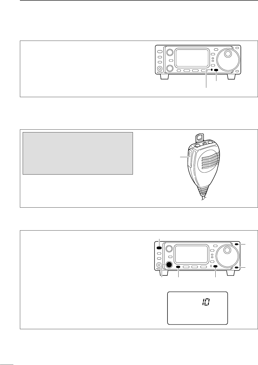
■Basic transmit operation
DTransmitting
25
3BASIC OPERATION
qPush [PTT] (microphone) to transmit.
• The [TX] indicator lights red.
wRelease [PTT] (microphone) to return to receive.
[PTT]
HM-103
Before transmitting, monitor your selected op-
erating frequency to make sure transmitting
won’t cause interference to other stations on
the same frequency. It’s good Amateur practice
to listen first, and then, even if nothing is heard,
ask “is the frequency in use” once or twice, be-
fore you begin operating on that frequency.
■Dial lock function
The dial lock function prevents accidental changes
caused by the tuning dial.
➥Push [LOCK] to turn the dial lock function ON and
OFF.
•“LOCK” indicator lights while the dial lock function is
activated.
Lights while the dial lock function is activated.
[LOCK]
DMaximum output power
q
Push [POWER] for 1 sec. to turn power OFF.
wWhile pushing [LOCK], push [POWER] to turn
power ON and enter initial set mode.
ePush [MENU] one or more times to select “1 MAX
POWSET,” if necessary.
• [M-CH] or [Y]/[Z] can also be used.
rRotate the main dial to select the desired maximum
output power.
•Maximum output power is selectable “0.5,” “1,” “2.5,” “5”
or “10.”
•Default setting is “10.”
tPush [POWER] to turn power OFF, and ON again.
1 MAX POWSET
[M-CH] [LOCK][MENU]
[POWER]
[Y]
[Z]
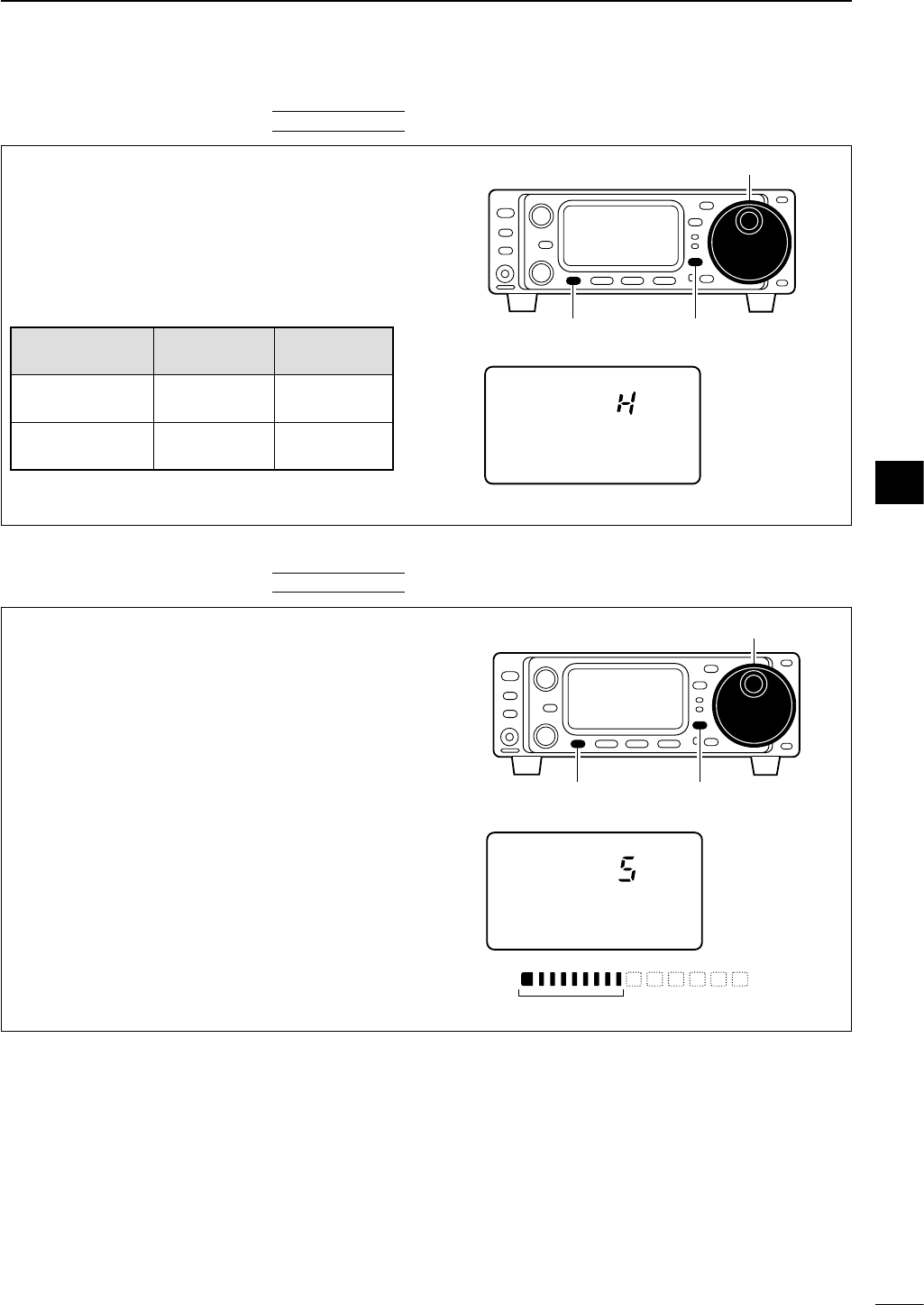
26
3
BASIC OPERATION
q
Push [DISPLAY] for 1 sec. to select quick set mode.
wPush [MENU] one or more times to select “Q1 RF
POWER.”
eRotate the main dial to select the desired output.
•Output power is displayed in 11 steps (L, 1–9 and H)
but is continuously selectable.
rPush [DISPLAY] to exit quick set mode.
•Available power
*Carrier power
P
O
S1
5
5379
20 40
10
60dB
USB
Q1 RF POWER
Maximum output
power is selected.
[DISPLAY]
Main dial
[MENU]
DSetting output power
Microphone gain must be adjusted properly so that
your signal does not distort when transmitted.
qSelect SSB or another phone mode (AM or FM
mode).
w
Push [DISPLAY] for 1 sec. to select quick set mode.
ePush [MENU] one or more times to select “Q2
MIC GAIN.”
•The ALC meter is selected automatically when operat-
ing in SSB mode.
rWhile speaking into the microphone adjust the mi-
crophone gain so that the ALC meter does not
peak past the ALC zone.
tPush [DISPLAY] to exit quick set mode.
ALC
ALC zone
ALC
S1 5379
20 40 60dB
USB
Q2 MIC GAIN
Microphone gain
is set to 5.
[DISPLAY]
Main dial
[MENU]
DSetting microphone gain
QUICK SET MODE
Power supply
SSB/CW AM*
voltage
RTTY/FM
13.8 V 0.1–10 W 0.1–4 W
(DC power mode)
9.6 V 0.1–5 W 0.1–2 W
(Battery mode)
QUICK SET MODE
3
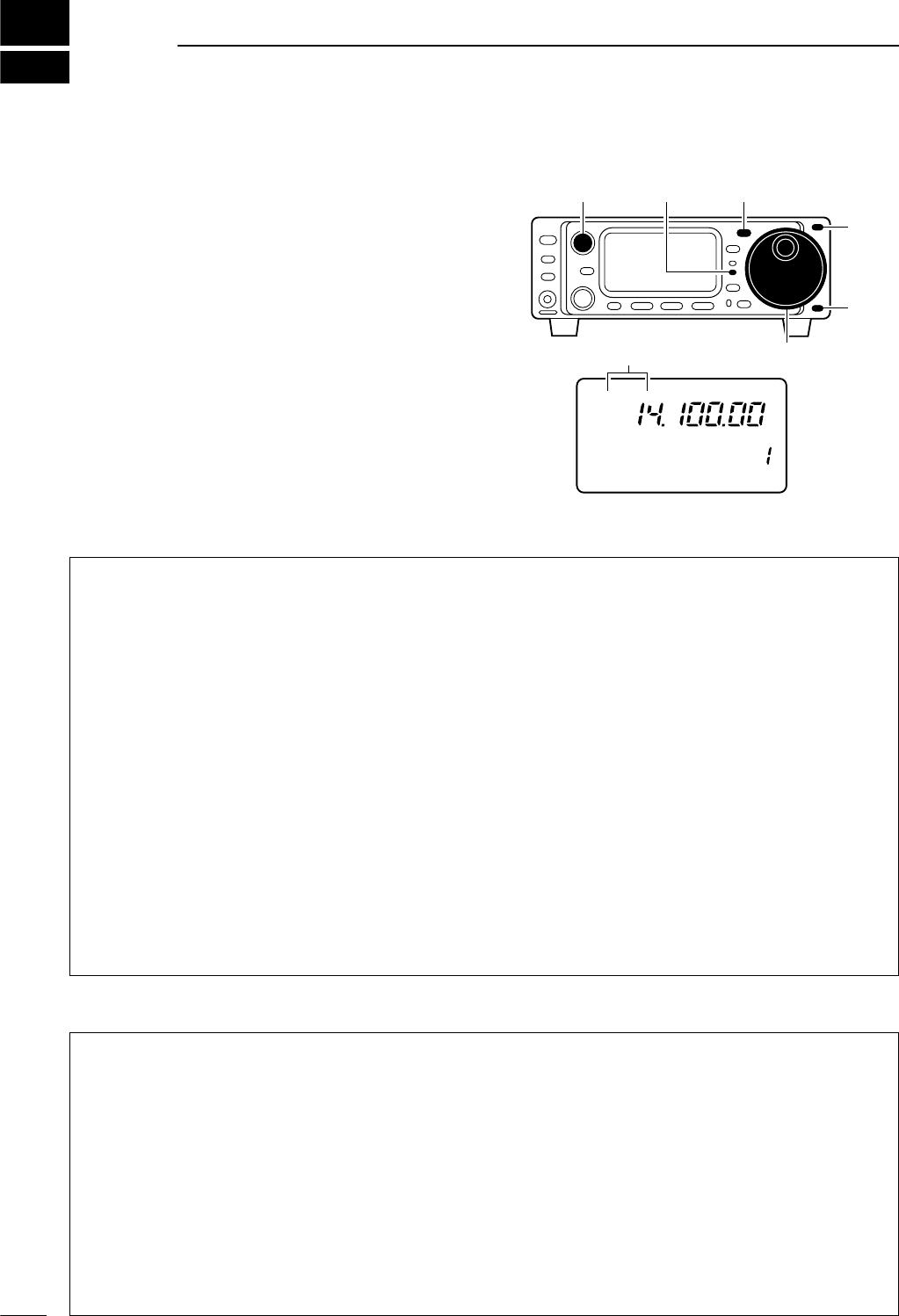
DConvenient functions for receive
DConvenient functions for transmit
4
27
RECEIVE AND TRANSMIT
■Operating SSB
qPush [(Y)BAND]/[(Z)BAND] to select the desired
band.
wPush [MODE] momentarily or push for 1 sec. to se-
lect LSB or USB mode.
•Below 10 MHz LSB is automatically selected; above
10 MHz USB is automatically selected.
eRotate [AF] control to set audio to a comfortable lis-
tening level.
rRotate the main dial to tune a desired signal.
• S-meter indicates received signal strength.
tPush [PTT] (microphone) to transmit.
• The TX indicator lights red.
ySpeak into the microphone at your normal voice
level.
• Adjust ‘MIC GAIN’ at this step, if necessary. (p. 26)
uRelease [PTT] (microphone) to return to receive.
R
LSB
CH
VFO A
P
O
S1
5
5379
20 40
10
60dB
USB CW R
TT
Y
AM WFM
M1 SPL A/B XFC
[TX] indicator [MODE]
Main dial
[AF]
[Y]
[Z]
“LSB” or “USB” appears
• Preamp and attenuator (p. 46)
➥Push [P.AMP/ATT] momentarily to set the preamp
ON or OFF.
•Lights green when the preamp is set to ON.
➥Push [P.AMP/ATT] for 1 sec. to set the attenuator
ON.
•Push [P.AMP/ATT] momentarily to turn the attenua-
tor OFF.
• Lights red when the attenuator is set to ON.
• Noise blanker (p. 48)
➥While “M3” is selected, push [(F-2)NB] to turn the
noise blanker ON and OFF.
•Push [DISPLAY] once or twice to select M.
•Push [MENU] one or more times to select M3.
• “NB” appears when the noise blanker is set to ON.
•Push [(F-2)NB] for 1 sec. to enter the noise blanker
set mode.
• IF shift (p. 47)
➥Rotate [SHIFT] control.
• AGC (auto gain control) (p. 48)
➥While “M4” is selected, push [(F-3)AGC] to select
AGC fast and AGC slow.
•Push [DISPLAY] once or twice to select M.
•Push [MENU] one or more times to select M4.
•“F
AGC
” appears when the fast time constant is se-
lected.
• Noise reduction (p. 50)
➥While “S4” is selected,
push [(F-2)NR] to turn the
noise reduction ON and OFF.
•Push [DISPLAY] once or twice to select S.
•Push [MENU] one or more times to select S4.
•Push [(F-3)NRL] then rotate [M-CH] to adjust the
noise reduction level.
• “NR” appears when the noise reduction is set to ON.
• Auto notch filter (p. 50)
➥While “S4” is selected,
push [(F-1)ANF] to turn th
e
auto notch filter function ON and OFF.
•“ANF” appears when the noise reduction is set to
ON.
• Speech compressor (p. 54)
➥While “M4” is selected, push [(F-2)COM] to turn
the speech compressor ON and OFF.
•Push [DISPLAY] once or twice to select M.
•Push [MENU] one or more times to select M4.
•“COM” appears when the speech compressor is set
to ON.
•Push [(F-2)COM] for 1 sec. to enter the compression
level set mode.
• Carrier frequency control (p. 75)
➥While “Q3” is selected, rotate main dial to adjust
the audio tone.
•Push [DISPLAY] for 1 sec. to enter the quick set
mode.
•Push [MENU] one or more times to select Q3.
• VOX (voice operated transmit) (p. 53)
➥While “M4” is selected, push [(F-1)VOX] to turn
the VOX function ON and OFF.
•Push [DISPLAY] once or twice to select M.
•Push [MENU] one or more times to select M4.
• “VOX” appears when the VOX function is set to ON.
•Push [(F-1)VOX] for 1 sec. to enter the VOX set mode.
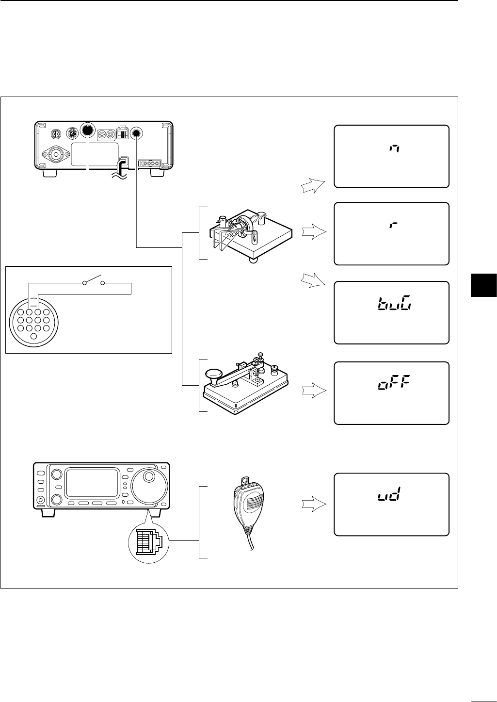
28
4
RECEIVE AND TRANSMIT
DConnections for CW
■Operating CW
Rear panel
CW
K4 CW PADDLE
K4 CW PADDLE
K4 CW PADDLE
K4 CW PADDLE
K4 CW PADDLE
CW
CW
CW
CW
Paddle
[KEY]
[MICROPHONE]
Straight key
Microphone
Keyer set mode setting
Rear panel
4
8
12
[ACC]
123
765
9
1011
13
For no break-in operation:
Connect an external switch
such as a foot switch; or use
the RTTY SEND terminal for
all bands. (See p. 38)
See p. 31 for connection details:
Paddle operation from front panel
MIC connector
.
Normal
Reverse
Bug
4
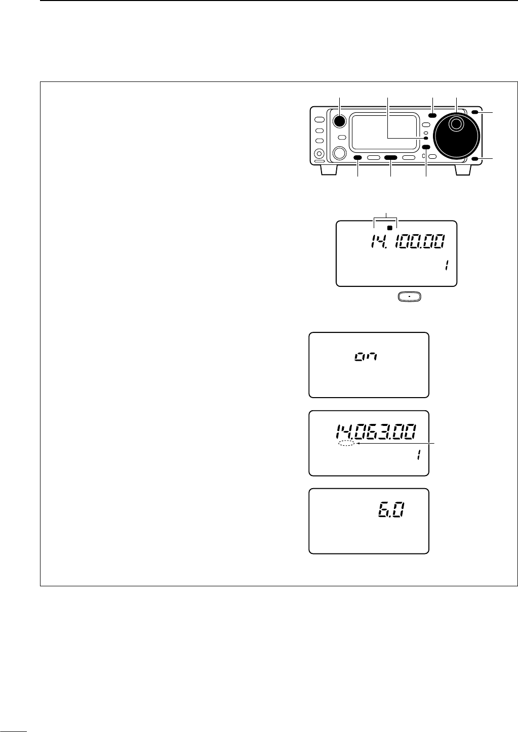
29
4RECEIVE AND TRANSMIT
DCW operation
qConnect a paddle or straight key as at previous
page.
wPush [(Y)BAND]/[(Z)BAND] to select the desired
band.
ePush [MODE] momentarily to select CW mode.
•After CW mode is selected, push [MODE] for 1 sec. to
toggle between CW and Memory keyer modes.
rWhile the quick set mode item “Q3” is selected in
CW mode, rotate main dial to select CW or CWå
mode.
•Push [DISPLAY] for 1 sec. to enter the quick set mode.
•Push [MENU] one or more times to select Q3.
•Push [DISPLAY] momentarily to return to normal oper-
ating mode.
tRotate [AF] control to set audio to a comfortable
listening level.
yRotate the main dial to simultaneously tune a de-
sired signal and its side tone.
uSet CW setting in the keyer set mode.
•Push [DISPLAY] once or twice to select M.
• Push [MENU] one or more times to select M4.
•Push [(F-2)KEY] for 1 sec. to enter the keyer set mode.
(p. 32)
iSet CW break-in operation as semi break-in, full
break-in or OFF.
•Push [MENU] one or more times to select “K1 BK-
IN.”
•Rotate the main dial to select CW break-in operation.
➧FULL: full break-in
➧on : semi break-in
➧OFF : no break-in (ACC socket connection is neces-
sary as at previous page.)
oSet the CW delay time when semi break-in opera-
tion is selected.
•Push [MENU] one or more times to select “K2 BK-
IN DELAY.”
•Rotate the main dial to set the desired delay time (see
p. 32 for details).
!0 Keying to transmit, use the electric keyer or pad-
dle to key your CW signals.
• The TX indicator lights red.
•The Po meter indicates transmitted CW signal
strength.
!1 Release keying to return to receive.
BK VFO A
CW
CW
K2 BK-IN DELAY
M4 KEY1/4 AGC
Delay time of 6.0
dots is selected
for semi break-in
operation.
CH
P
O
S1
5
53792040
10
60dB
CW
K1 BK-IN
Semi break-in
operation is
selected.
Appears
R
LSB
CH
VFO A
P
O
S1
5
5379
20 40
10
60dB
USB CW R
TT
Y
AM WFM
M4 1/4 KEY AGC
F 2
[TX] indicator [MODE] Main dial
[DISPLAY][F-2][MENU]
[AF]
[Y]
[Z]
“CW” or “CWå” appears
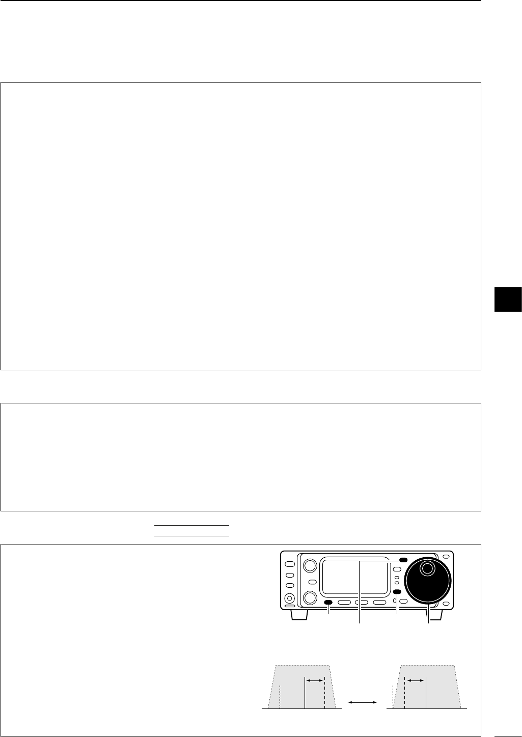
30
4
RECEIVE AND TRANSMIT
• Preamp and attenuator (p. 46)
➥Push [P.AMP/ATT] momentarily to set the preamp
ON or OFF.
•Lights green when the preamp is set to ON.
➥Push [P.AMP/ATT] for 1 sec. to set the attenuator
ON.
•Push [P.AMP/ATT] momentarily to turn the attenua-
tor OFF.
• Lights red when the attenuator is set to ON.
• Noise blanker (p. 48)
➥While “M3” is selected, push [(F-2)NB] to turn the
noise blanker ON and OFF.
•Push [DISPLAY] once or twice to select M.
•Push [MENU] one or more times to select M3.
• “NB” appears when the noise blanker is set to ON.
•Push [(F-2)NB] for 1 sec. to enter the noise blanker
set mode.
• AGC (auto gain control) (p. 48)
➥While “M4” is selected, push [(F-3)AGC] to select
AGC fast and AGC slow.
•Push [DISPLAY] once or twice to select M.
•Push [MENU] one or more times to select M4.
•“F
AGC
” appears when the fast time constant is se-
lected.
• IF shift (p. 47)
➥Rotate [SHIFT] control.
• Noise reduction (p. 50)
➥While “S4” is selected,
push [(F-2)NR] to turn the
noise reduction ON and OFF.
•Push [DISPLAY] once or twice to select S.
•Push [MENU] one or more times to select S4.
•Push [(F-3)NRL] then rotate [M-CH] to adjust the
noise reduction level.
•“NR” appears when the noise reduction is set to ON.
• Auto notch filter (p. 50)
➥While “S4” is selected,
push [(F-1)ANF] to turn th
e
auto notch filter function ON and OFF.
•“ANF” appears when the noise reduction is set to
ON.
•1⁄4function
➥While “M4” is selected, push [(F-1)1/4] to turn
the 1⁄4function ON and OFF.
•Push [DISPLAY] once or twice to select M.
•Push [MENU] one or more times to select M4.
• Break-in function (p. 32)
➥While “M4” is selected, push [(F-2)KEY] for 1 sec.
to enter the keyer set mode.
•Push [DISPLAY] once or twice to select M.
•Push [MENU] one or more times to select M4.
➥Rotate the main dial to select the break-in OFF,
semi break-in or full break-in.
•“BK” or “F-BK” appears when the semi break-in or full
break-in is set to ON, respectively.
DConvenient functions for receive
DConvenient functions for transmit
DCW reverse mode
The CWå(CW Reverse) mode receives CW signals
with a reverse side CW carrier point like that of LSB
and USB modes. Use this mode when interference
signals are near the desired signal and you want to
change the interference tone.
qSelect CW mode with [MODE].
w
Push [DISPLAY] for 1 sec. to enter quick set mode.
ePush [MENU] one or more times to select “Q3 CW
REV,” then rotate the main dial to select CW and
CWåmodes.
• Check the interference tone.
r
Push [DISPLAY] momentarily to exit quick set mode.
• Receive audio tone response
(Reverse) CWå(Normal) CW
BFO
600 Hz
signal
inteference signal
600 Hz
BFO
inteference
[MODE] Main dial
[DISPLAY][MENU]
QUICK SET MODE
4
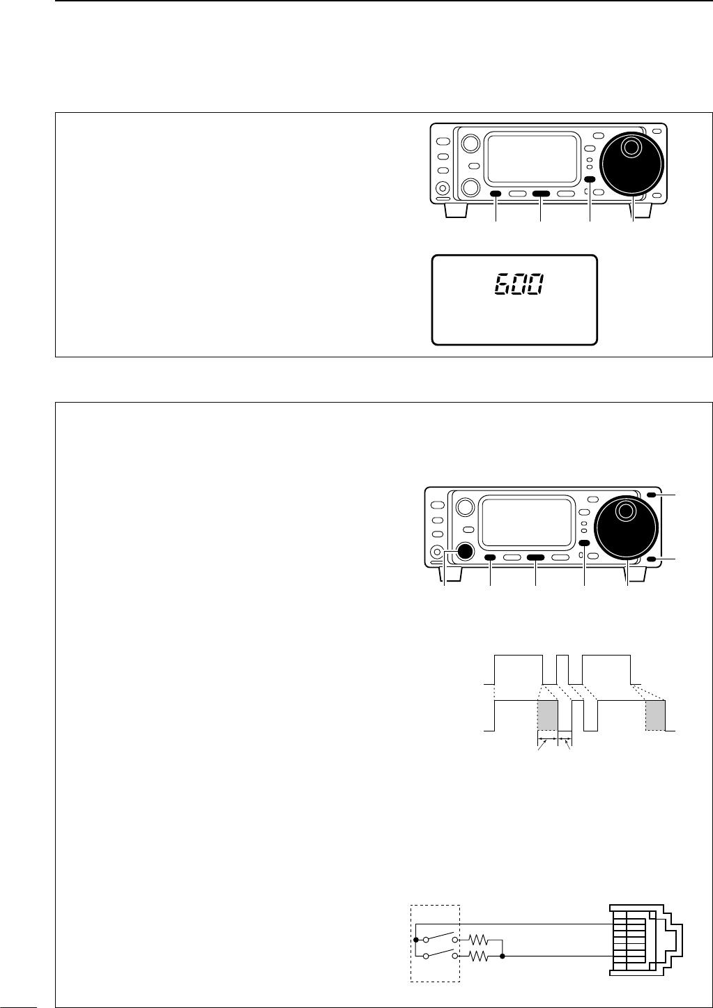
31
4RECEIVE AND TRANSMIT
DCW pitch control
The received CW audio pitch and monitored CW
audio pitch can be adjusted to suit your preferences
(300 to 900 Hz) without changing the operating fre-
quency.
qEnter the keyer set mode.
•Push [DISPLAY] once or twice to select M.
• Push [MENU] one or more times to select M4.
•Push [(F-2)KEY] for 1 sec. to enter the keyer set mode.
wPush [MENU] one or more times to select “K3 CW
PITCH,” then rotate the main dial to set the de-
sired pitch.
ePush [DISPLAY] to exit the keyer set mode.
K3 CW PITCH
CW This shows the
default setting for
the CW pitch
control (600 Hz).
Main dial[DISPLAY][MENU] [F-2]
DElectronic CW keyer
The IC-703 has an electronic keyer. Both keying
speed and weight (the ratio of dot :space:dash) can
be set.
• Setting the electronic keyer
qEnter the keyer set mode.
•
Push [DISPLAY] once or twice to select M.
• Push [MENU] one or more times to select M4.
•Push [(F-2)KEY] for 1 sec. to enter the keyer set mode.
wPush [MENU] one or more times to select “K4 CW
PADDLE,” then rotate the main dial to select the
paddle type.
•When “ud” is selected, the up/down switches on the mi-
crophone can be used as a paddle.
ePush [MENU] one more time to select item “K5
RATIO,” then rotate the main dial to select the de-
sired weight.
• Key weight can be selected from 2.8 to 4.5.
•Check the selected ratio with the side tone function in
CW mode.
r
Push [DISPLAY] momentarily to return to
M4
.
t
Push [DISPLAY] for 1 sec. to enter quick set mode.
yPush [MENU] once or twice to select “Q2 KEY
SPEED,” then rotate the main dial to select the de-
sired keying speed.
•[M-CH] or [Y]/[Z] can also be used to select “Q2 KEY
SPEED.”
• Keying speed can be selected from 6 to 60 wpm.
u
Push [DISPLAY] momentarily to return to
M4
.
Paddle operation from front panel MIC connector
Connect a CW paddle as at right to operate an elec-
tronic keyer from the front panel MIC connector.
•This function is available from the front panel mic
connector only.
•Be sure to select item “n,” “r,” “buG” or “oFF” in K4
CW PADDLE in the keyer set mode. (p. 32)
• Connect straight key to “DOT” side.
front panel
MIC connector
MIC U/D
CW
paddle
DOT E
DASH
w
u
3.9 kΩ±5%
2.2 kΩ±5%
KEYING WEIGHT EXAMPLE: morse code “K”
DASH
Weight setting:
1:1:3 (default)
Weight setting:
Adjusted
DASH
DOT
(Fixed*)
Adjustable range SPACE (Fixed*)
*SPACE and DOT length can be adjusted
with “Q2 KEY SPEED” only.
Main dial[DISPLAY][MENU] [F-2][M-CH]
[Y]
[Z]
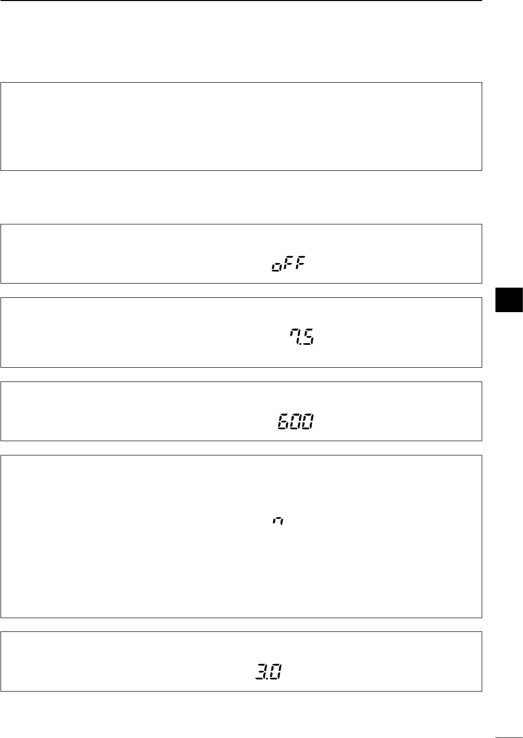
While M4 is selected in CW mode, push [(F-2)KEY] for
1 sec. to enter the keyer set mode.
32
4
RECEIVE AND TRANSMIT
K1 BK-IN
This item sets the CW break-in operation. The break-
in operation is selectable from off, on and FULL.
The default is OFF.
CW
K2 BK-IN DELAY
This item adjusts break-in delay time for CW semi
break-in operation. The delay time is selectable from
2.0 to 13.0 (dots).
The default is 7.5 dots.
CW
K3 CW PITCH
This item sets the CW pitch. CW pitch is adjustable
from 300 to 900 Hz in 10 Hz steps.
The default is 600 Hz.
CW
K4 CW PADDLE
This item adjusts the CW paddle type. Four selec-
tions are available.
• n : normal (for electronic keyer use)
• r : reverse (for electronic keyer use)
•buG : When using the electronic keyer, key down
produces a “dash,” releasing the key automat-
ically produces a “dot(s).”
•oFF : Turns OFF the electronic keyer (for straight
key use)
• ud : For using the microphone’s [UP]/[DN] keys in-
stead of the CW paddle.
The default is “n,” normal.
CW
K5 RATIO
This item adjusts the CW key ratio (or weight). The
ratio can be selected from 2.8 to 4.5.
The default is 3.0.
CW
DCW side tone function
DKeyer set mode
When the transceiver is in the receive condition (and
the break-in function is OFF— below) you can listen
to the tone of your CW signal without actually trans-
mitting. This allows you to match your transmit signal
exactly to another station’s. This also convenient for
CW practice. CW side tone level can be adjusted in
the initial set mode (p. 77).
4
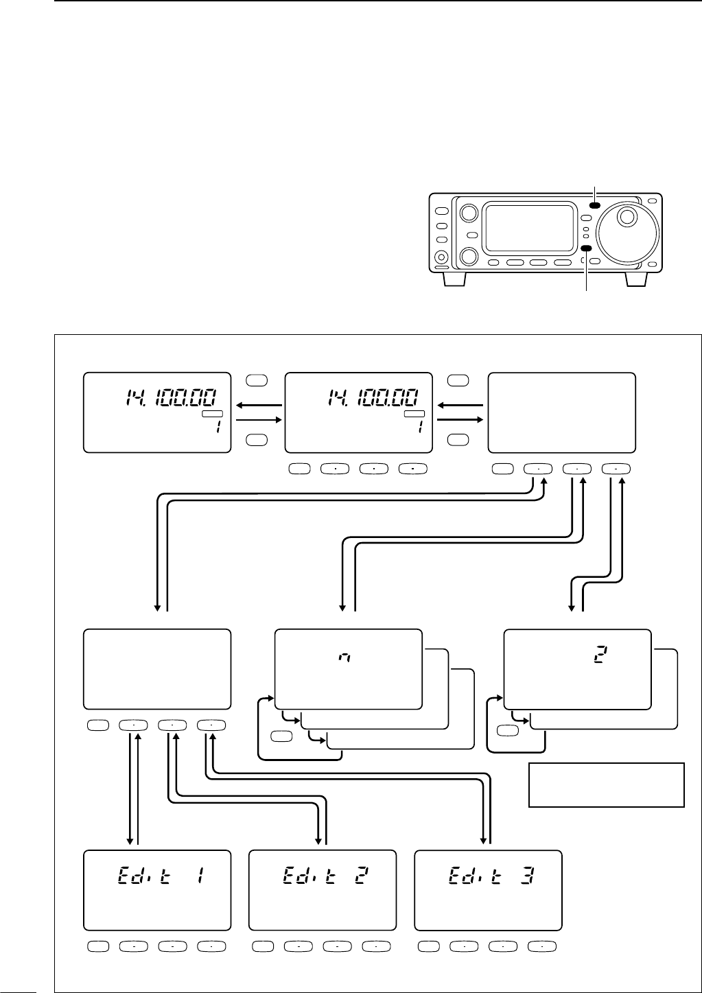
33
4RECEIVE AND TRANSMIT
The transceiver has a number of convenient functions
for the electronic keyer that can be accessed from the
memory keyer menu.
qSelect CW mode with [MODE].
wPush [MODE] for 1 sec. to select the memory
keyer send menu.
•Push [MODE] momentarily to return to normal CW op-
erating mode.
ePush [DISPLAY] to enter the memory keyer menu.
See the diagram below.
•Push [DISPLAY] momentarily to return to the memory
keyer send menu.
[DISPLAY]
[MODE]
CH
VFO A
P
O
S1
1 1.5 2 3 5
5379
20 40
10
60dB
CW
∞
BLANK
CH
VFO A
P
O
S1
1 1.5 2 3 5
5379
20 40
10
60dB
∞
BLANK
M4 1/4 KEY AGC
CW
-1
MK1 MK2 MK3
F 1 F 2 F 3
MENU
F 1 F 2 F 3
MENU
F 1 F 2 F 3
MENU
F 1 F 2 F 3
MENU
CW
Ä
MK1 MK2 MK3
F 1 F 2 F 3
MENU
CW
Ä
EDT 001 SET
F 1 F 2 F 3
MENU
CW
Ä
ÅCFU TU Ç
_
Push [MENU](
Ä
)
or [DIAPLAY]
Push [MENU](
Ä
)
or [DIAPLAY]
Push [MENU](
Ä
)
or [DIAPLAY]
Push [MENU](
Ä
)
or [DIAPLAY]
CW
Ä
ÅUR 5NN* BÇ
_
CW
Ä
ÅCQ TEST CÇ
_
MENU
MENU
CW
02 MSG DISPLAY
CW
01 REPEAT TIME
CW
03 PRESENT No.
CW
02 CNT UP TRIG
CW
01 NUM STYLE
MODE
MODE
DISPLAY
DISPLAY
• CW mode
• Edit menu • Contest number set mode • Menory keyer set mode
• Memory keyer send menu • Memory keyer menu
Push Push
Push
Push Push Push Push* Push*
*Set mode item can be selected
with [Y BAND]/[Z BAND] or
[M-CH] during set mode.
Push [F-1]
Push
[DISPLAY]
Push
[DISPLAY]
Push [F-2]
Push [F-3]
Push
for 1 sec.
■Memory keyer functions
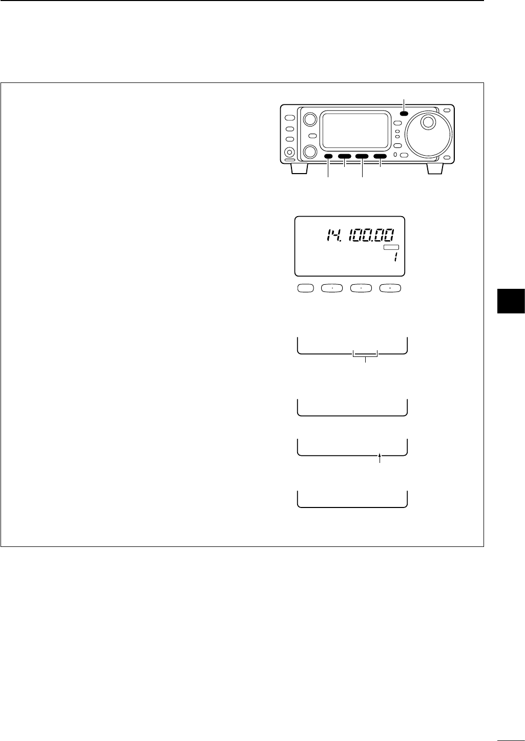
34
4
RECEIVE AND TRANSMIT
Pre-set characters can be sent using the memory
keyer send menu. Contents of the memory keyer are
set using the edit menu.
• Transmitting
qSelect CW mode with [MODE].
wPush [MODE] for 1 sec. to enter the memory keyer
send menu.
eSet the break-in function ON (p. 32).
•When step ris performed during the break-in func-
tion OFF, monitors the memory keyer contents.
rPush one of the function keys ([(F-1)MK1] to
[(F-3)MK3]) to send the contents of the memory
keyer.
•Pushing a function key for 1 sec. repeatedly sends the
contents and blinks “MK1,” “MK2” or “MK3” indication;
push any function key to cancel the transmission.
•Keying with the connected straight key or paddle to
[KEY] on the rear panel is also cancels the transmis-
sion.
• Under bars (___) are indicated for the count up trig-
ger set channel.
•The contest number counter is incremented each time
the contents are sent.
• Push [MENU] to reduce the contest number count by 1
when resending contents to unanswered calls.
tPush [MODE] momentarily to exit memory keyer
send menu and return to normal CW mode indica-
tion.
-1
CQ TEST CQ
-1
MK1 MK2 MK3
---
-1
UR 5NN001 B
-1
CFM TU
• Memory keyer send menu
•MK1 send indication
•MK2 send indication
•MK3 send indication
Count up trigger
indication
Counter
CW
-1
MK1 MK2 MK3
F 1 F 2 F 3
MENU
CH
VFO A
P
O
S1
5
5379
20 40
10
60dB
CW
BLANK
---
Sends [(F-1)MK1]–[(F-3)MK3] contents.
• Memory keyer send menu
[MENU]
[F-3][F-1]
[F-2]
[MODE]
DMemory keyer send menu
4
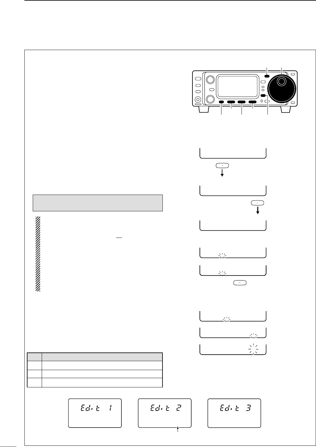
35
4RECEIVE AND TRANSMIT
The contents of the memory keyer memories can be
set using the memory keyer edit menu. The memory
keyer can memorize and re-transmit 3 CW key codes
for often-used CW sentences, contest numbers, etc.
Total capacity of the memory keyer is 50 characters
per memory channel.
• Programming contents
qSelect CW mode with [MODE].
wEnter the memory keyer menu.
•Push [MODE] for 1 sec. to enter the memory keyer
send menu.
•Push [DISPLAY] momentarily to enter the memory
keyer menu.
ePush [(F-1)EDT] to enter the edit menu.
rPush the multi-function key, [(F-1)MK1], [(F-2)MK2]
or [(F-3)MK3], to select the desired memory keyer
channel to be edited.
tInput the desired character by rotating the main
dial.
• Selectable characters (with the main dial);
NOTE:
“^” is used to transmit a following word with no
space such as
AR
. Put “^” before a text string
such as ^AR, and the string “
AR
” is sent with no
space.
“*” is used to insert the CW contest number.
The contest number automatically increments
by 1. This function is only available for one
memory keyer channel at a time. Memory keyer
channel MK2 used “*” by default.
Push [(F-2)] to erase characters.
yPush [(F-1)ç] or [(F-3)å] to move the cursor back-
wards or forwards, respectively.
uRepeat steps tand yto input the desired char-
acters.
iPush [MENU] or [DISPLAY] three times to return
to the keyer send menu.
Pre-programmed contents
Ä
MK1 MK2 MK3
Ä
EDT 001 SET
Ä
Å [ DEL] Ç
Ä
ÅCFU TU Ç
-
Ä
ÅÇ
-
-
Ä
ÅQ Ç
Ä
ÅSL TU D Ç
Ä
ÅYUA TEST Ç
-
F 1
F 2
F 3
Displays “[DEL]” for 1 sec. then shows
the default contents.
Push [F-2] to erase characters.
• Example display— when inputting QSL TU
DE JA3YUA TEST into MK3
• Memory keyer menu
• Edit menu
•MK3 indication (default)
Push
Push
[MENU] [DISPLAY]
[F-3][F-1]
[F-2]
[MODE] Main dial
CW
Ä
ÅCFU TU Ç
_
CW
Ä
ÅUR 5NN* BÇ
_
CW
Ä
ÅCQ TEST CÇ
_
•MK1 indication (default) •MK2 indication (default) •MK3 indication (default)
Contest number counter is set
by entering an asterisk (*).
A B C D E F G H I J K L M N O P Q R S T
U V W X Y Z / ? . , * ^
CH CONTENTS
MK1 CQ TEST CQ TEST DE ICOM ICOM T
MK2 UR 5NN* BK
MK3 CFM TU
DEditing a memory keyer
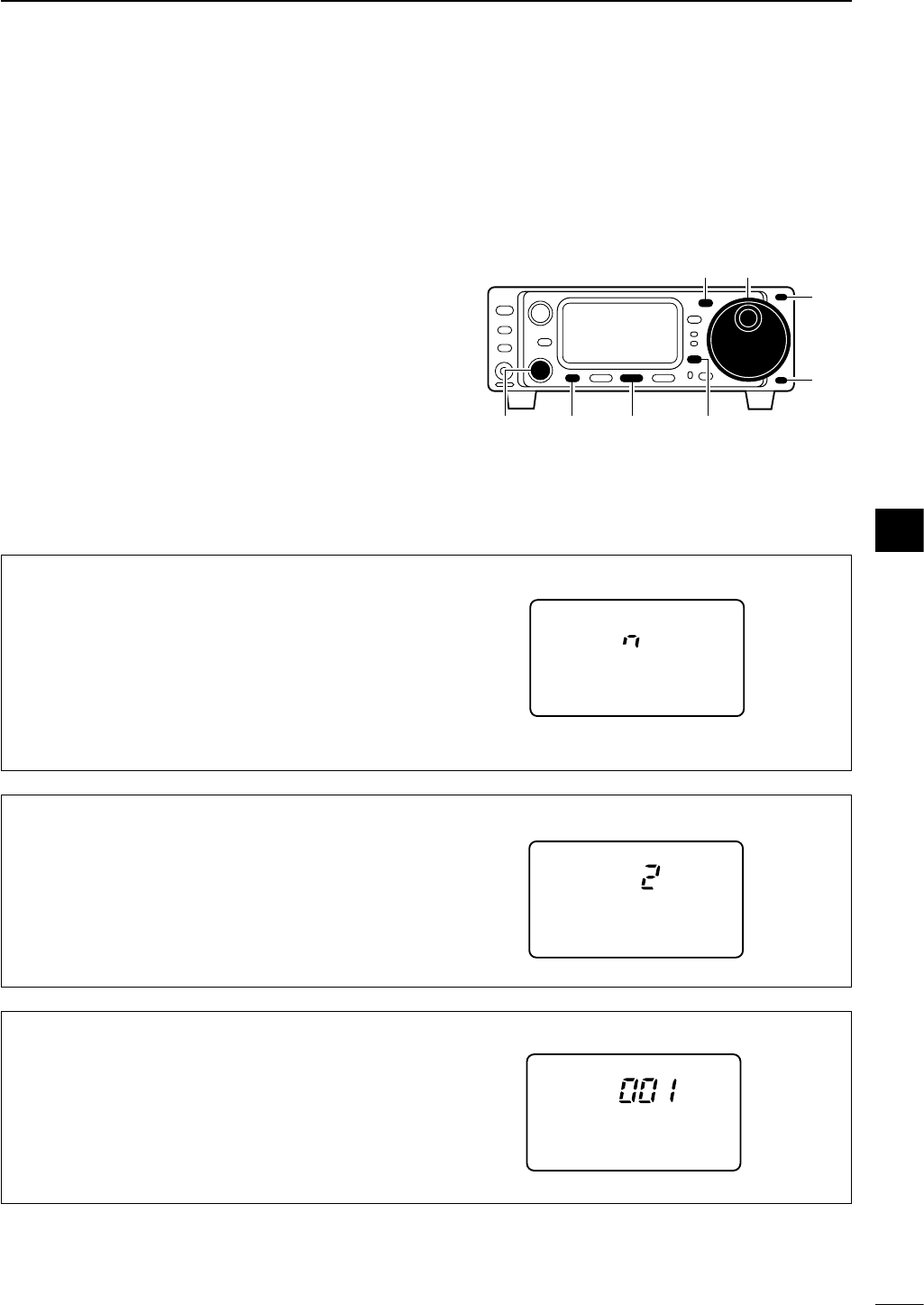
36
4
RECEIVE AND TRANSMIT
DContest number set mode
This menu is used to set the contest (serial) number
and count up trigger, etc.
• Setting contents
qSelect CW mode with [MODE].
wEnter the memory keyer menu.
•Push [MODE] for 1 sec. to enter the memory keyer
send menu.
•Push [DISPLAY] momentarily to enter the memory
keyer menu.
ePush [(F-2)001] to enter the contest number set
mode.
rPush [MENU] once or twice to select the desired set
item.
• [M-CH] or [Y]/[Z] can also be used.
tSet the desired condition using the main dial.
yPush [DISPLAY] twice to return to the memory
keyer send menu.
[MENU] [DISPLAY][M-CH] [F-2]
[MODE] Main dial
[Y]
[Z]
02 CONT UP TRIG (Count up trigger)
This selects which of the three memory slots will have
the contest serial number exchange. The count up
trigger allows the serial number automatically incre-
mented after each complete serial number exchange
is sent.
• 1 (MK1), 2 (MK2) and 3 (MK3) can be set. (default: 2)
CW
02 CNT UP TRIG
01 NUM STYLE (Number style)
This item sets the numbering system used for contest
(serial) numbers— normal or morse cut numbers.
n : Does not use morse cut number (default)
190.Ano: Sets 1 as A, 9 as N and 0 as O.
190.Ant : Sets 1 as A, 9 as N and 0 as T.
90.no : Sets 9 as N and 0 as O.
90.nt : Sets 9 as N and 0 as T.
CW
01 NUM STYLE
03 PRESENT No. (Present number)
This item shows the current number for the count up
trigger channel set above.
•Rotate the tuning dial to change the number.
CW
03 PRESENT No.
4
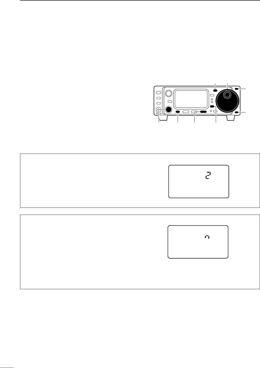
37
4RECEIVE AND TRANSMIT
DMemory keyer set mode
This set mode is used to set the memory keyer repeat
time and indication type of the messages.
• Setting contents
qSelect CW mode with [MODE].
wEnter the memory keyer menu.
•Push [MODE] for 1 sec. to enter the memory keyer
send menu.
•Push [DISPLAY] momentarily to enter the memory
keyer menu.
ePush [(F-3)SET] to enter the memory keyer set
mode.
rPush [MENU] to select the desired set item.
• [M-CH] or [Y]/[Z] can also be used.
tSet the desired condition using the main dial.
yPush [DISPLAY] twice to return to the memory
keyer send menu.
[MENU] [DISPLAY][M-CH] [F-3]
[MODE] Main dial
[Y]
[Z]
01 REPEAT TIME (Repeat time)
When sending CW using the repeat timer, this item
sets the time between transmission.
• 1 to 60 sec. in 1 sec. steps can be selected.
CW
01 REPEAT TIME
02 MSG DISPLAY (Message display)
This item sets the indication type of the messages
(pre-set characters).
n : Normal indication (default)
[(F-1)MK1], [(F-2)MK2], [(F-3)MK3]
3 : First three characters of the massages are in-
dicated.
e.g. [(F-1)CQ ], [(F-2)UR ], [(F-3)CFM]
3.cn : First three characters of the massages and
contest number are indicated.
e.g. [(F-1)CQ ], [(F-2)001], [(F-3)CFM]
CW
02 MSG DISPLAY
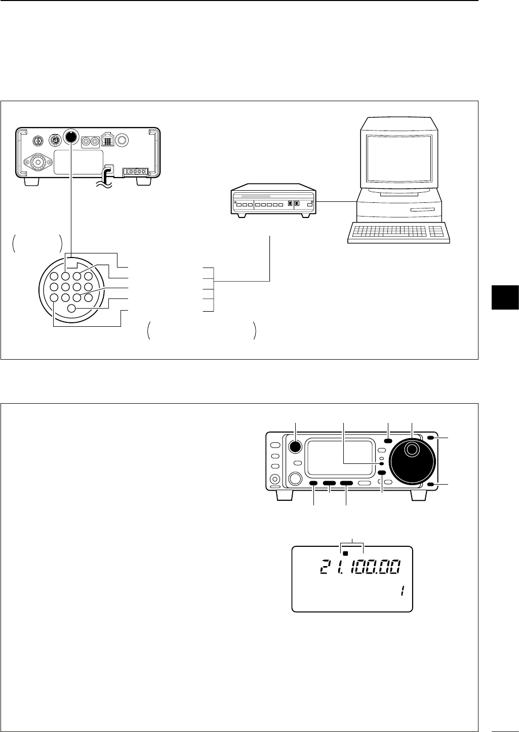
38
4
RECEIVE AND TRANSMIT
DConnections for RTTY (FSK)
4
8
12
[ACC]
123
765
9
1011
13
Rear panel
TU or TNC
Personal computer
Rear panel
view
Colors refer to connection
to the supplied ACC cable.
*1Connect SQL line when required.
MSEND (orenge)
GND (red)
FSKK (black)
SQL*1 (light green)
AF out (light blue)
■Operating RTTY
DRTTY (FSK) operation
qConnect a terminal unit as at above.
wPush [(Y)BAND]/[(Z)BAND] to select the desired
band.
ePush [MODE] momentarily to select RTTY mode.
•After RTTY mode is selected, push [MODE] for 1 sec.
to toggle between RTTY and SSB-D modes.
rWhile the quick set mode item “Q2” is selected in
RTTY mode, rotate main dial to select RTTY or
åRTTY mode.
•Push [DISPLAY] for 1 sec. to enter the quick set mode.
•Push [MENU] one or more times to select Q2.
•Push [DISPLAY] momentarily to return to normal oper-
ating mode.
tRotate [AF] to set audio to a comfortable listening
level.
ySelect the desired FSK tone/shift frequencies and
keying polarity as at page 40.
uRotate the main dial to tune a desired signal.
•Use [(F-1)1/4] in the M4 display when critical setting is
required.
•S-meter indicates received signal strength.
•If the received signal cannot be demodulated, try se-
lecting åRTTY mode (or RTTY mode).
iTransmit a SEND signal from your TNC.
•The TX indicator lights red.
•T
he Po meter indicates transmitted RTTY signal
strength.
oOperate the connected PC or TNC (TU) to trans-
mit RTTY (FSK) signals.
R
LSB
CH
VFO A
P
O
S1
5
5379
20 40
10
60dB
USB CW R
TT
Y
AM WFM
M4 1/4 TON AGC
[TX] indicator [MODE] Main dial
[DISPLAY][F-1]
[MENU] [F-2]
[AF]
[Y]
[Z]
“RTTY” or “åRTTY” appears
4
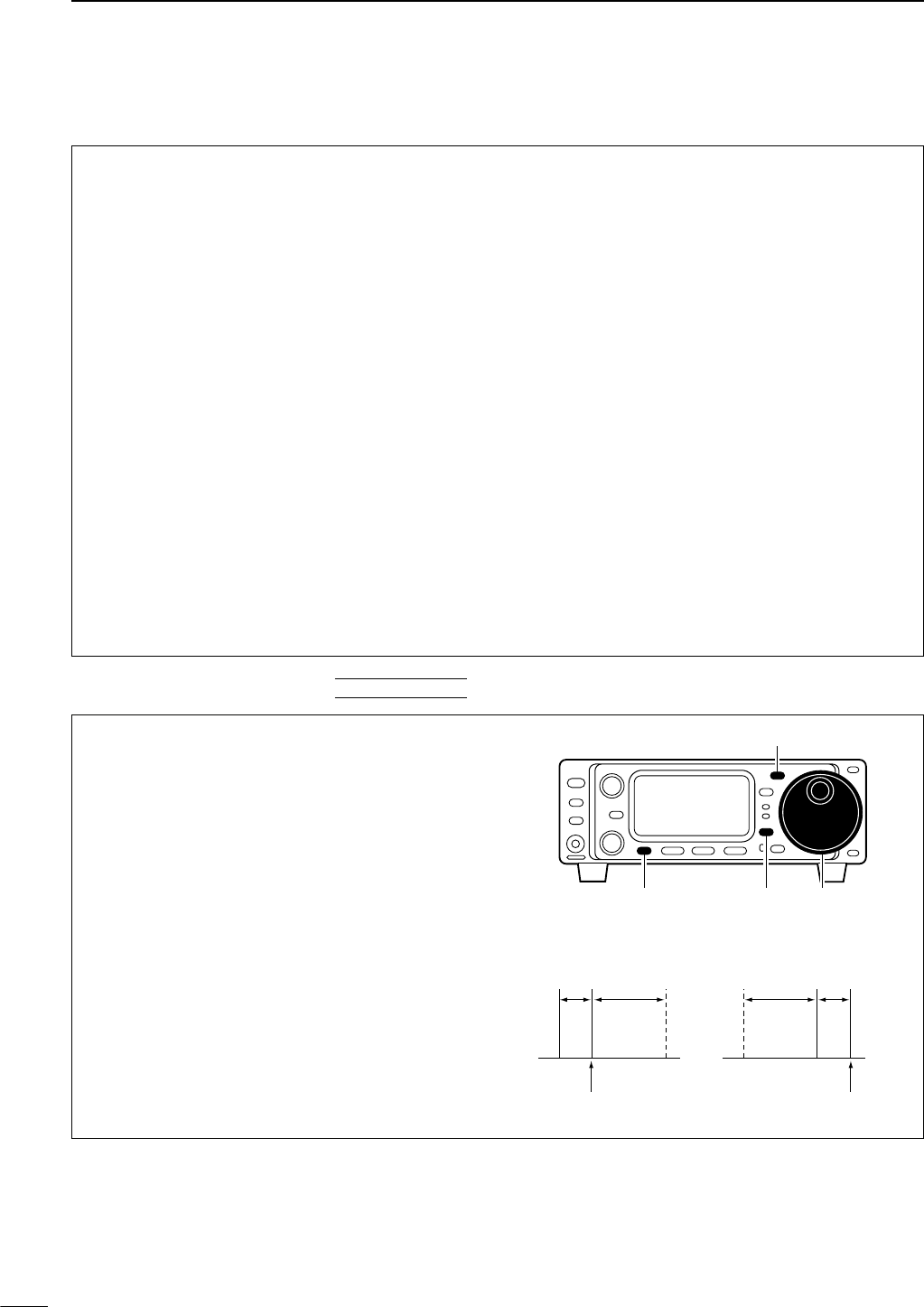
39
4RECEIVE AND TRANSMIT
• Preamp and attenuator (p. 46)
➥Push [P.AMP/ATT] momentarily to set the preamp
ON or OFF.
•Lights green when the preamp is set to ON.
➥Push [P.AMP/ATT] for 1 sec. to set the attenuator
ON.
•Push [P.AMP/ATT] momentarily to turn the attenua-
tor OFF.
• Lights red when the attenuator is set to ON.
• Noise blanker (p. 48)
➥While “M3” is selected, push [(F-2)NB] to turn the
noise blanker ON and OFF.
•Push [DISPLAY] once or twice to select M.
•Push [MENU] one or more times to select M3.
• “NB” appears when the noise blanker is set to ON.
•Push [(F-2)NB] for 1 sec. to enter the noise blanker
set mode.
• AGC (auto gain control) (p. 48)
➥While “M4” is selected, push [(F-3)AGC] to select
AGC fast and AGC slow.
•Push [DISPLAY] once or twice to select M.
•Push [MENU] one or more times to select M4.
•“F
AGC
” appears when the fast time constant is se-
lected.
• IF shift (p. 47)
➥Rotate [SHIFT] control.
• Noise reduction (p. 50)
➥While “S4” is selected,
push [(F-2)NR] to turn the
noise reduction ON and OFF.
•Push [DISPLAY] once or twice to select S.
•Push [MENU] one or more times to select S4.
•Push [(F-3)NRL] then rotate [M-CH] to adjust the
noise reduction level.
• “NR” appears when the noise reduction is set to ON.
• Auto notch filter (p. 50)
➥While “S4” is selected,
push [(F-1)ANF] to turn th
e
auto notch filter function ON and OFF.
•“ANF” appears when the noise reduction is set to
ON.
•1⁄4function
➥While “M4” is selected, push [(F-1)1/4] to turn
the 1⁄4function ON and OFF.
•Push [DISPLAY] once or twice to select M.
•Push [MENU] one or more times to select M4.
DConvenient functions for receive
DRTTY reverse mode
Received characters are occasionally garbled when
the receive signal is reversed between MARK and
SPACE. This reversal can be caused by incorrect
TNC connections, settings, commands, etc.
To receive a reversed RTTY signal correctly, select
åRTTY (RTTY reverse) mode.
qSelect RTTY mode with [MODE].
w
Push [DISPLAY] for 1 sec. to enter quick set mode.
ePush [MENU] one or more times to select “Q2
RTTY REV,” then rotate the main dial to select
RTTY and åRTTY modes.
• Check the interference tone.
r
Push [DISPLAY] momentarily to exit quick set mode.
ReverseNormal
BFO
170
Hz
2125
Hz 170
Hz
2125
Hz
BFO
Mark
Space
displayed freq.displayed freq.
Mark
Space
[MODE]
Main dial[DISPLAY][MENU]
QUICK SET MODE
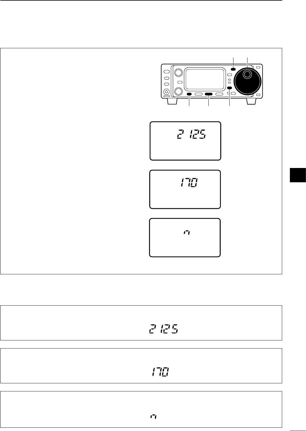
40
4
RECEIVE AND TRANSMIT
DPresetting for RTTY
Tone frequency
qPush [MODE] momentarily to select RTTY mode.
•After RTTY mode is selected, push [MODE] for 1 sec.
to toggle between RTTY and SSB-D modes.
wEnter the RTTY tone set mode.
•
Push [DISPLAY] once or twice to select M.
• Push [MENU] one or more times to select M4.
•Push [(F-2)TON] for 1 sec. to enter the RTTY tone set
mode (below).
ePush [MENU] one or more times to select “R1
RTTY TONE,” then rotate the main dial to select
the desired frequency.
Shift frequency
qEnter the RTTY tone set mode as same as above.
wPush [MENU] one or more times to select “R2
RTTY SHIFT,” then rotate the main dial to select
the desired shift frequency.
RTTY keying
qEnter the RTTY tone set mode as same as above.
wPush [MENU] one or more times to select R3
RTTY KEYING; then rotate the main dial to se-
lect the desired keying polarity.
After presetting is finished, push [DISPLAY] momen-
tarily to return the normal operating mode.
R
TT
Y
R3 RTTY KEYING
RTTY keying is set to
‘normal’.
normal :
key open=mark
key close=space
reverse:
key open=space
key close=mark
R
TT
Y
R2 RTTY SHIFT
RTTY shift frequency
is set to 170 Hz.
170/200/425 Hz are
available.
R
TT
Y
R1 RTTY TONE
RTTY mark frequency
is set to 2125 Hz.
2125, 1615 and 1275
Hz are available.
[MODE] Main dial
[DISPLAY][MENU] [F-2]
R3 RTTY KEYING (RTTY only)
This item adjusts the RTTY keying. Normal or reverse
keying can be selected.
The default is “n,” normal.
Normal : key open=mark
Reverse : key open=space
R
TT
Y
R1 RTTY TONE
This item selects the RTTY tone. RTTY tone is se-
lected between 1275, 1615 and 2125 Hz.
The default is 2125 Hz.
R
TT
Y
R2 RTTY SHIFT
This item adjusts the RTTY shift. There are 3 selec-
table values: 170, 200 and 425 Hz.
The default is 170 Hz.
R
TT
Y
While M4 is selected in RTTY mode, push [(F-2)TON]
for 1 sec. to enter the RTTY tone set mode.
DRTTY tone set mode
4
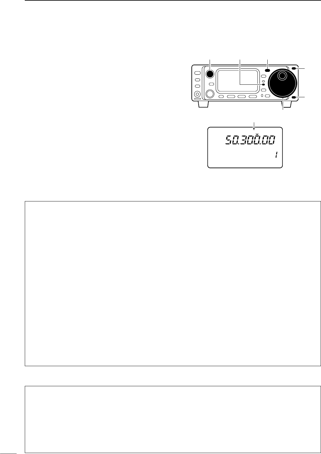
41
4RECEIVE AND TRANSMIT
DConvenient functions for receive
DConvenient functions for transmit
■Operating AM
qPush [(Y)BAND]/[(Z)BAND] to select the desired
band.
wPush [MODE] momentarily or push for 1 sec. to se-
lect AM mode.
•After FM or AM mode is selected, push [MODE] for
1 sec. to toggle between FM and AM modes.
eRotate [AF] control to set audio to a comfortable lis-
tening level.
rRotate the main dial to tune a desired signal.
•S-meter indicates received signal strength.
•The default tuning step for AM mode is 1 kHz; this can
be changed using the tuning step program mode. (p.19)
tPush [PTT] (microphone) to transmit.
•The TX indicator lights red.
ySpeak into the microphone at your normal voice
level.
•Adjust ‘MIC GAIN’ at this step, if necessary. (p. 26)
uRelease [PTT] (microphone) to return to receive.
R
LSB
CH
VFO A
P
O
S1
5
5379
20 40
10
60dB
USB CW R
TT
Y
AM WFM
M1 SPL A/B XFC
[TX] indicator [MODE]
Main dial
[AF]
[Y]
[Z]
“AM” appears
• Preamp and attenuator (p. 46)
➥Push [P.AMP/ATT] momentarily to set the preamp
ON or OFF.
•Lights green when the preamp is set to ON.
➥Push [P.AMP/ATT] for 1 sec. to set the attenuator
ON.
•Push [P.AMP/ATT] momentarily to turn the attenua-
tor OFF.
• Lights red when the attenuator is set to ON.
• Noise blanker (p. 48)
➥While “M3” is selected, push [(F-2)NB] to turn the
noise blanker ON and OFF.
•Push [DISPLAY] once or twice to select M.
•Push [MENU] one or more times to select M3.
• “NB” appears when the noise blanker is set to ON.
•Push [(F-2)NB] for 1 sec. to enter the noise blanker
set mode.
•Initial set mode item “30 AM NB” (p. 80) is must be
set ON when noise blanker function is used in AM
mode. (Default setting is ON.)
• IF shift (p. 47)
➥Rotate [SHIFT] control.
• AGC (auto gain control) (p. 48)
➥While “M4” is selected, push [(F-3)AGC] to select
AGC fast and AGC slow.
•Push [DISPLAY] once or twice to select M.
•Push [MENU] one or more times to select M4.
•“F
AGC
” appears when the fast time constant is se-
lected.
• Noise reduction (p. 50)
➥While “S4” is selected,
push [(F-2)NR] to turn the
noise reduction ON and OFF.
•Push [DISPLAY] once or twice to select S.
•Push [MENU] one or more times to select S4.
•Push [(F-3)NRL] then rotate [M-CH] to adjust the
noise reduction level.
• “NR” appears when the noise reduction is set to ON.
• Auto notch filter (p. 50)
➥While “S4” is selected,
push [(F-1)ANF] to turn th
e
auto notch filter function ON and OFF.
•“ANF” appears when the noise reduction is set to
ON.
• Speech compressor (p. 54)
➥While “M4” is selected, push [(F-2)COM] to turn
the speech compressor ON and OFF.
•Push [DISPLAY] once or twice to select M.
•Push [MENU] one or more times to select M4.
•“COM” appears when the speech compressor is set
to ON.
•Push [(F-2)COM] for 1 sec. to enter the compression
level set mode.
• VOX (voice operated transmit) (p. 53)
➥While “M4” is selected, push [(F-1)VOX] to turn
the VOX function ON and OFF.
•Push [DISPLAY] once or twice to select M.
•Push [MENU] one or more times to select M4.
• “VOX” appears when the VOX function is set to ON.
•Push [(F-1)VOX] for 1 sec. to enter the VOX set
mode.
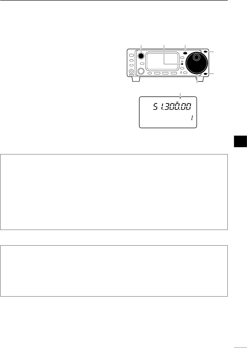
42
4
RECEIVE AND TRANSMIT
DConvenient functions for receive
DConvenient functions for transmit
■Operating FM
qPush [(Y)BAND]/[(Z)BAND] to select the desired
band.
wPush [MODE] momentarily or for 1 sec. to select
FM mode.
•After FM or AM mode is selected, push [MODE] for
1 sec. to toggle between FM and AM modes.
eRotate [AF] control to set audio to a comfortable lis-
tening level.
rRotate the main dial to tune a desired signal.
•S-meter indicates received signal strength.
•The default tuning step for FM mode is 1 kHz; this can
be changed using the tuning step program mode. (p.19)
tPush [PTT] (microphone) to transmit.
•The TX indicator lights red.
ySpeak into the microphone at your normal voice
level.
•Adjust ‘MIC GAIN’ at this step, if necessary. (p. 26)
uRelease [PTT] (microphone) to return to receive.
R
LSB
CH
VFO A
P
O
S1
5
5379
20 40
10
60dB
USB CW R
TT
Y
AM WFM
M1 SPL A/B XFC
[TX] indicator [MODE]
Main dial
[AF]
[Y]
[Z]
“FM” appears
• Preamp and attenuator (p. 46)
➥Push [P.AMP/ATT] momentarily to set the preamp
ON or OFF.
•Lights green when the preamp is set to ON.
➥Push [P.AMP/ATT] for 1 sec. to set the attenuator
ON.
•Push [P.AMP/ATT] momentarily to turn the attenua-
tor OFF.
• Lights red when the attenuator is set to ON.
• IF shift (p. 47)
➥Rotate [SHIFT] control.
• Noise reduction (p. 50)
➥While “S4” is selected,
push [(F-2)NR] to turn the
noise reduction ON and OFF.
•Push [DISPLAY] once or twice to select S.
•Push [MENU] one or more times to select S4.
•Push [(F-3)NRL] then rotate [M-CH] to adjust the
noise reduction level.
• “NR” appears when the noise reduction is set to ON.
• Auto notch filter (p. 50)
➥While “S4” is selected,
push [(F-1)ANF] to turn th
e
auto notch filter function ON and OFF.
•“ANF” appears when the noise reduction is set to
ON.
• VOX (voice operated transmit) (p. 53)
➥While “M4” is selected, push [(F-1)VOX] to turn
the VOX function ON and OFF.
•Push [DISPLAY] once or twice to select M.
•Push [MENU] one or more times to select M4.
• “VOX” appears when the VOX function is set to ON.
•Push [(F-1)VOX] for 1 sec. to enter the VOX set
mode.
4
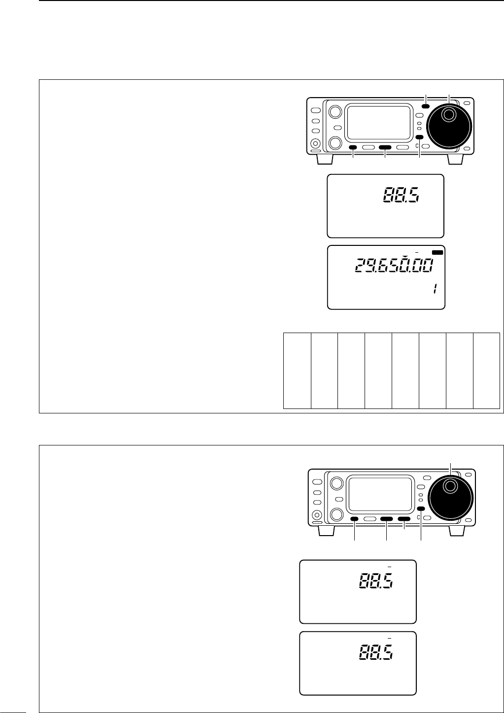
43
4RECEIVE AND TRANSMIT
Tone squelch operation is a method of communica-
tions using selective calling. Only received signals
having a matching tone will open the squelch. Before
communicating using tone squelch, all members of
your party must agree on the tone squelch frequency
to use.
qPush [MODE] one or more times to select FM
mode.
wSelect M4.
•Push [DISPLAY] once or twice to select M.
• Push [MENU] one or more times to select M4.
ePush [(F-2)TON] for 1 sec. to enter the FM tone set
mode.
•Push [MENU] one or more times to select “T2 TONE
SQL.”
rRotate the main dial to set the desired subaudible
tone frequency.
•See left table for available tone frequencies.
•Push [DISPLAY] to exit the FM tone set mode.
tPush [(F-2)TON] once or twice to turn the tone
squelch function.
•“TSQL” appears.
yCommunicate in the usual manner.
• Push [PTT] to transmit; release to receive.
• Available tone squelch frequencies (Unit: Hz)
CH
VFO A
P
O
S1
5
5379
20 40
10
60dB
FM TSQL
SPL
M4 VOX TON
T2 TONE SQL
FM
[MODE] Main dial
[DISPLAY][MENU] [F-2]
DTone squelch operation
By monitoring a signal that is being transmitted on a
repeater input frequency, you can determine the tone
frequency necessary to open a repeater.
qDuring tone squelch or repeater operation (“T” or
“TSQL” is displayed, select M4.
•Push [DISPLAY] once or twice to select M.
• Push [MENU] one or more times to select M4.
wPush [(F-2)TON] for 1 sec. to enter the FM tone set
mode.
•Push [MENU] one or more times to select “T3 T-SQL
SCN” during tone squelch operation or “T3 RPTR-T
SCN” during repeater operation.
•If tone squelch function or tone encoder has not been
selected, this item does not appear.
ePush [(F-3)SCN] to toggle the tone scan operation
ON and OFF.
•While scanning, tone frequencies are displayed instead
of the operating frequency.
•When a matched tone is detected, tone scan automati-
cally stops, the matched tone is displayed and the re-
peater tone (or tone squelch tone) setting is
automatically adjusted accordingly.
rPush [DISPLAY] to exit the FM tone set mode.
During repeater
operation.
P
O
S1
5
53792040
10
60dB
FM T
T3 RPTR-T SCN
During tone squelch
operation.
P
O
S1
5
53792040
10
60dB
FM TSQL
T3 T-SQL SCN
Main dial
[DISPLAY][MENU] [F-2]
[F-3]
67.0
69.3
71.9
74.4
77.0
79.7
82.5
085.4
088.5
091.5
094.8
097.4
100.0
103.5
107.2
110.9
114.8
118.8
123.0
127.3
131.8
136.5
141.3
146.2
151.4
156.7
159.8
162.2
165.5
167.9
171.3
173.8
177.3
179.9
183.5
186.2
189.9
192.8
196.6
199.5
203.5
206.5
210.7
218.1
225.7
229.1
233.6
241.8
250.3
254.1
DTone scan operation
44
4
RECEIVE AND TRANSMIT
T3 RPTR-T SCN
(Repeater tone scan)
During repeater operation, you can detect the tone
frequency necessary to open a repeater. (see p. 45)
The default is 88.5 Hz.
FM-T
T3 T-SQL SCN
(Tone squelch tone scan)
During tone squelch operation, you can detect the
tone frequency necessary to communicate using tone
squelch. (see p. 43)
The default is 88.5 Hz.
FM-TSQL
T1 RPTR TONE
This item selects a subaudible tone for FM-T mode
operation to access a repeater. There are 50 tones
available from 67.0 Hz to 254.1 Hz (see table at
right). • Available subaudible tone frequencies (Unit: Hz)
The default is 88.5 Hz.
FM
T2 TONE SQL
This item sets a subaudible tone for tone squelch use.
The same subaudible tone frequencies as for re-
peater operation are available—see above
The default is 88.5 Hz.
FM
While M4 is selected in FM mode, push [(F-2)TON] for
1 sec. to enter the FM tone set mode.
DFM tone set mode
67.0
69.3
71.9
74.4
77.0
79.7
82.5
085.4
088.5
091.5
094.8
097.4
100.0
103.5
107.2
110.9
114.8
118.8
123.0
127.3
131.8
136.5
141.3
146.2
151.4
156.7
159.8
162.2
165.5
167.9
171.3
173.8
177.3
179.9
183.5
186.2
189.9
192.8
196.6
199.5
203.5
206.5
210.7
218.1
225.7
229.1
233.6
241.8
250.3
254.1
4
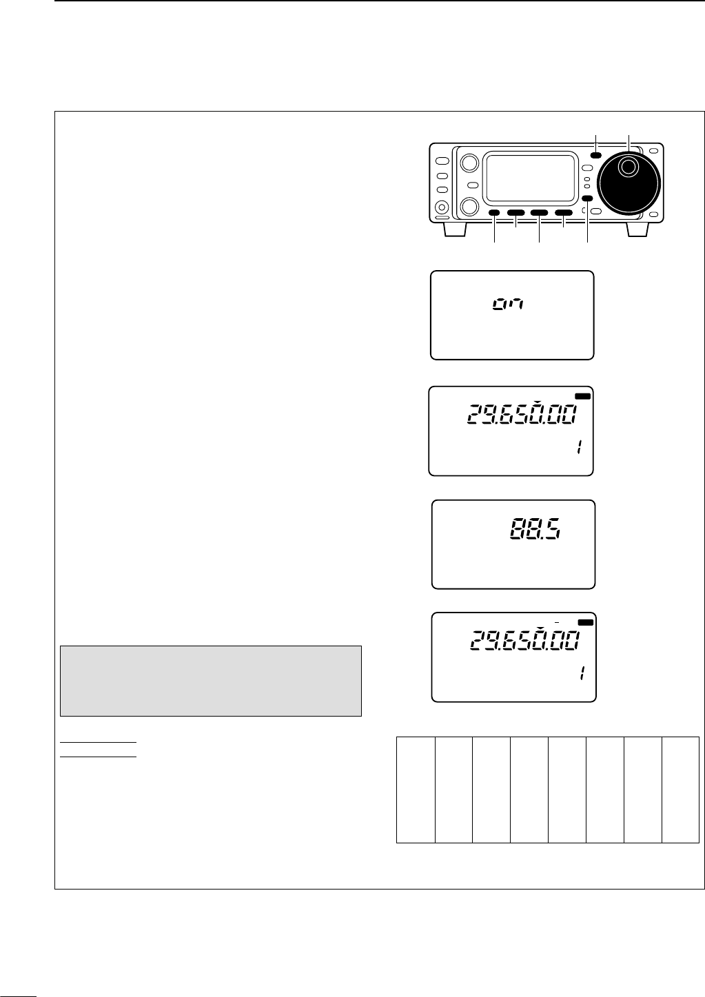
45
4RECEIVE AND TRANSMIT
■Repeater operation
A repeater amplifies received signals and re-transmits
them at a different frequency. When using a repeater,
the transmit frequency is shifted from the receive fre-
quency by an offset frequency. A repeater can be ac-
cessed using split frequency operation with the shift
frequency set to the repeater’s offset frequency.
qSet the offset frequency and turn ON the quick split
function in initial set mode in advance (pgs. 79, 80).
•If the quick split function is turned OFF, both transmit
and receive must be set separately.
wPush [MODE] one or more times to select FM
mode, then set the receive frequency.
eSelect M1.
•Push [DISPLAY] once or twice to select M.
•Push [MENU] one or more times to select M1.
rPush [(F-1)SPL] for 1 sec. to activate the split fre-
quency function with the pre-selected offset.
tSelect M4.
•Push [MENU] one or more times to select M4.
yPush [(F-2)TON] for 1 sec. to enter the FM tone set
mode.
•If FM mode has not been selected, this item does not
appear.
•Push [MENU] one or more times to select “T1 RPTR
TONE.”
•Rotate the main dial to set a subaudible tone frequency.
•Push [DISPLAY] to exit the FM tone set mode.
uPush [(F-2)TON] to turn the tone encoder.
•“T” appears.
iTo check the repeater input frequency (direct sig-
nal from the other station), push and hold
[(F-3)XFC]in the M1 display.
oTo return to simplex operation, push [(F-1)SPL] in
the M1 display.
Each memory channel can store a tone frequency
and an offset frequency, as well as the operating fre-
quency. Store repeater information into memory chan-
nels for quick and easy access to repeaters.
• Available subaudible tone frequencies (Unit: Hz)
CH
VFO A
P
O
S1
5
5379
20 40
10
60dB
FM T
SPL
M4 VOX TON
T1 RPTR TONE
Set the tone fre-
quency.
See below table
for available fre-
quencies.
FM
CH
VFO A
P
O
S1
5
5379
20 40
10
60dB
FM
SPL
M1 SPL A/B XFC
24 QUICK SPLIT
Turn the quick
split function ON.
(Initial set mode
default is ON.)
[MODE] Main dial
[DISPLAY][MENU] [F-2]
[F-3][F-1]
CONVENIENT
NOTE: The split function may not be turned off
when you change the operating band, push
[(F-1)SPL] again to turn off the split function after
you finish the repeater operation.
67.0
69.3
71.9
74.4
77.0
79.7
82.5
085.4
088.5
091.5
094.8
097.4
100.0
103.5
107.2
110.9
114.8
118.8
123.0
127.3
131.8
136.5
141.3
146.2
151.4
156.7
159.8
162.2
165.5
167.9
171.3
173.8
177.3
179.9
183.5
186.2
189.9
192.8
196.6
199.5
203.5
206.5
210.7
218.1
225.7
229.1
233.6
241.8
250.3
254.1
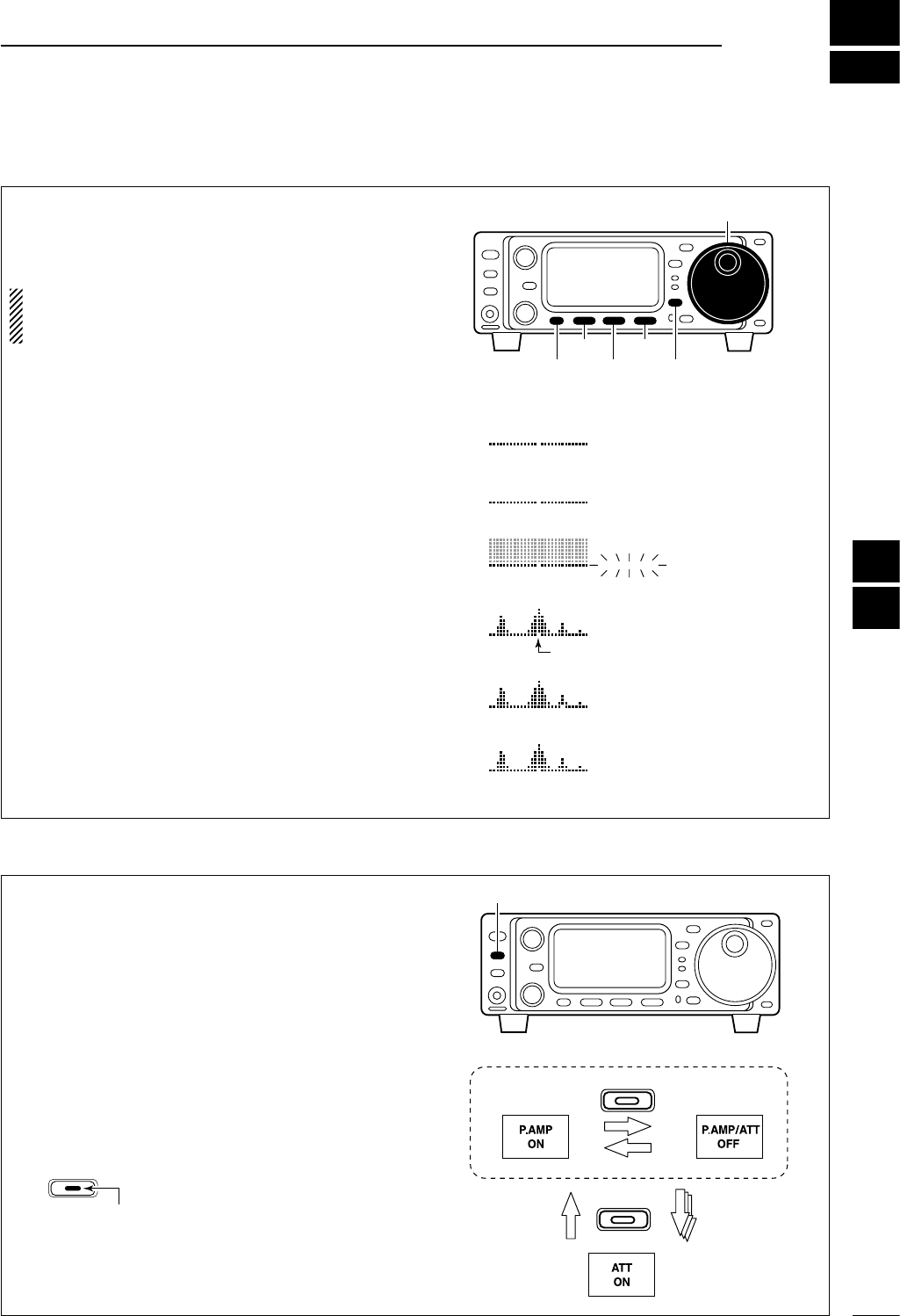
5
46
FUNCTION FOR RECEIVE
■Simple band scope
This function allows you to visually “sweep” an area
surrounding the set frequency for other signals. De-
tected signals are indicated graphically in the dot ma-
trix section of the display.
NOTE:
Use the attenuator or turn OFF the preamp
when using the band scope on a band containing a lot
of noise.
qSet a mode and frequency.
wSelect G1.
•Push [DISPLAY] once or twice to select G.
• Push [MENU] one or more times to select G1.
ePush [F-1] one or more times to select the desired
steps.
•Each dot corresponds to a step for the indicated fre-
quency.
•0.5k, 1k, 2k, 5k, 10k, 20k and 0.1M (100 kHz) can be
set for the scope step.
rPush [F-3] to start the sweep.
•“___” (below SWP) flashes while sweeping.
• The receive audio is muted while sweeping.
tRotate the main dial if you want to monitor the dis-
played signals.
•The sweep marker indicates the location of the dis-
played frequency in the sweep readout.
•If the displayed frequency is outside of the sweep read-
out (determined by the sweep width), the sweep marker
flashes.
yPush [F-2] to return the frequency to the start of a
sweep.
• The sweep marker moves back to the center position.
1k SWP
2k SWP
2k SWP
2k SWP
___
2k SWP
Select sweep width
([F-1])
Start sweep
([F-3])
Sweep is finished
([F-3] again)
Move sweep marker
(main dial)
2k SWP Returns to previous
frequency ([F-2])
sweep marker
Main dial
[DISPLAY][MENU] [F-2]
[F-3][F-1]
■Preamp and attenuator
The preamp amplifies received signals in the front
end circuit to improve the S/N ratio and sensitivity.
Turn this function ON when receiving weak signals.
The attenuator prevents desired signals from distort-
ing when very strong signals are near the desired fre-
quency or when very strong electric fields, such as
from broadcasting stations, are near your location.
Push [P.AMP/ATT] momentarily to turn the preamp ON
and OFF; push for 1 sec. to turn the attenuator ON.
•Lights green when the preamp is ON; lights red when
the 20 dB attenuator is ON.
• Only one of these functions can be activated at a time.
momentarily
momentarily 1 sec.
P.AMP/ATT
P.AMP/ATT
[P.AMP/ATT]
P.AMP/ATT
Lights green while the preamp is activated;
lights red while the attenuator is activated.
4
5
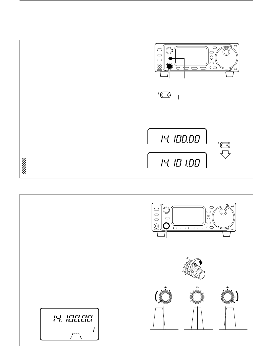
The IF shift function electronically changes the pass-
band frequency of the IF (intermediate frequency)
and cuts out higher or lower frequency components
of the IF to reject interference. The function shifts the
IF frequency up to ±1.2 kHz in 15 Hz steps in
SSB/CW/RTTY modes and up to ±250 Hz in 3 Hz
steps in CW-ã/RTTY-ãmodes. The IF shift is not
available in FM and AM modes.
(ã: Narrow)
qAdjust the [SHIFT] control for a minimum interfer-
ence signal level.
•The audio tone may be changed while the IF shift is in
use.
wSet the shift control to its center position when
there is no interference.
• Graphic display
The IF shift is displayed graphically (for about 1 sec.)
each time the shift control is rotated.
M-CH M-CH M-CHSHIFT
M-CH SHIFT
SHIFT SHIFT
Shifts low Center Shifts high
SHIFT
[SHIFT]
CH
VFO A
S1 5379204060dB
USB
■RIT function
The RIT (Receive Incremental Tuning) function com-
pensates for off-frequencies of communicating sta-
tions. The function shifts the receive frequency up to
±9.99 kHz in 10 Hz steps without moving the transmit
frequency. “21 SUB DIAL” item in initial set mode
must be set to RIT mode in advance. (p. 79)
qPush [RIT].
•The [RIT] indicator lights red.
wRotate the [M-CH] control to cancel the off-fre-
quencies.
• The transmit frequency is not shifted.
eTo cancel the RIT function, push [RIT] again.
• The [RIT] switch indicator goes out.
• Calculate function
The shift frequency of the RIT function can be
added/subtracted to the displayed frequency.
While the RIT indicator is lit, push and hold [RIT] for
1 sec.
NOTE:
The RIT function is not available in FM or
AM modes regardless of the Initial Set mode set-
ting. (p. 79)
Push for
1 sec.
USB
USB
RIT
SUB
RIT
SUB
Indicator lights red while
RIT function is activated.
[M-CH] [RIT]
■IF shift function
47
5FUNCTION FOR RECEIVE
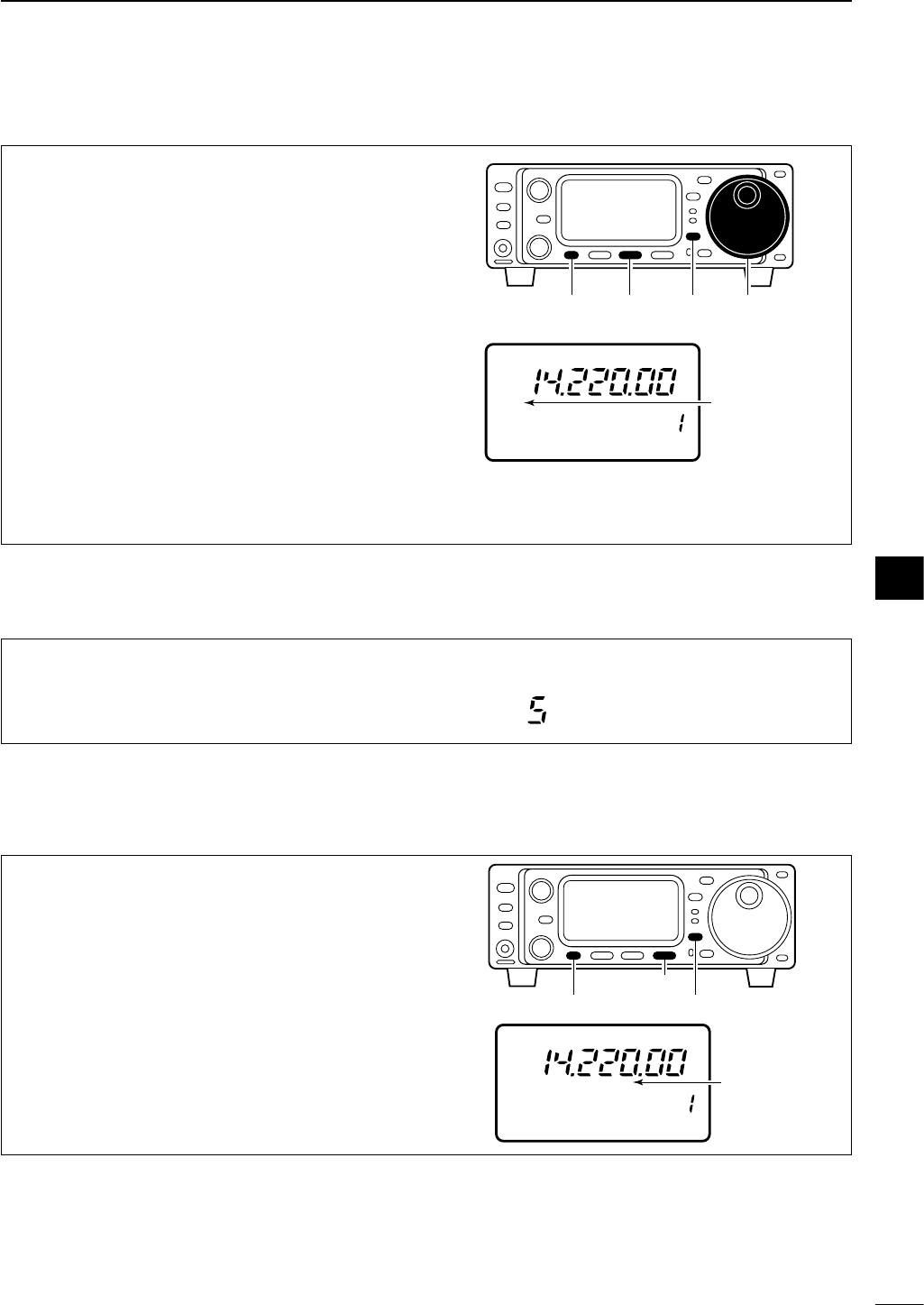
48
5
FUNCTION FOR RECEIVE
■Noise blanker
■AGC time constant
The noise blanker reduces pulse-type noise such as
that generated by automobile ignition systems. This
function is not effective for FM mode or for non pulse-
type noise. If you don’t want to use the noise blanker
for AM communications, the “30 AM NB” item in initial
set mode must be turned OFF (ON is the default set-
ting—p. 80).
qSelect M3.
•Push [DISPLAY] once or twice to select M.
• Push [MENU] one or more times to select M3.
wPush [(F-2)NB] to toggle the noise blanker ON and
OFF.
• “NB” appears when the noise blanker is turned ON.
ePush [(F-2)NB] for 1 sec. to enter the noise blanker
level set mode (below).
rRotate the main dial to set the noise blanker level.
tPush [DISPLAY] to exit the noise blanker level set
mode.
NB
CH
VFO A
S1 5379204060dB
USB
M3 FIL NB MET
P
O
510
Appears when
the noise blanker
is turned ON.
Main dial[DISPLAY][MENU] [F-2]
The AGC (Automatic Gain Control) controls receiver
gain to produce a constant audio output level even
when the received signal strength is varied by fading,
etc. Use AGC slow for normal phone operation; AGC
fast for receiving data and searching for signals. AGC
time constant cannot be changed in FM mode.
qSelect M4.
•Push [DISPLAY] once or twice to select M.
• Push [MENU] one or more times to select M4.
wPush [(F-3)AGC] to toggle the AGC time constant
between fast and slow.
•“FAGC” appears when the fast time constant is selected.
CH
VFO A
S1 5379204060dB
USB
M4 VOX COM AGC
FAGC
P
O
510
Appears when
AGC fast is
selected.
[DISPLAY][MENU]
[F-3]
N1 NB LEVEL
This item adjusts the noise blanker level. The noise
blanker level can be adjusted from 0 to 10.
The default is 5.
USB
Although noise blanker level set mode is available in all modes, the noise blanker function is not effective for FM
mode.
While M3 is selected in all modes, push [(F-2)NB] for
1 sec. to enter the noise blanker level set mode.
DNoise blanker level set mode 5
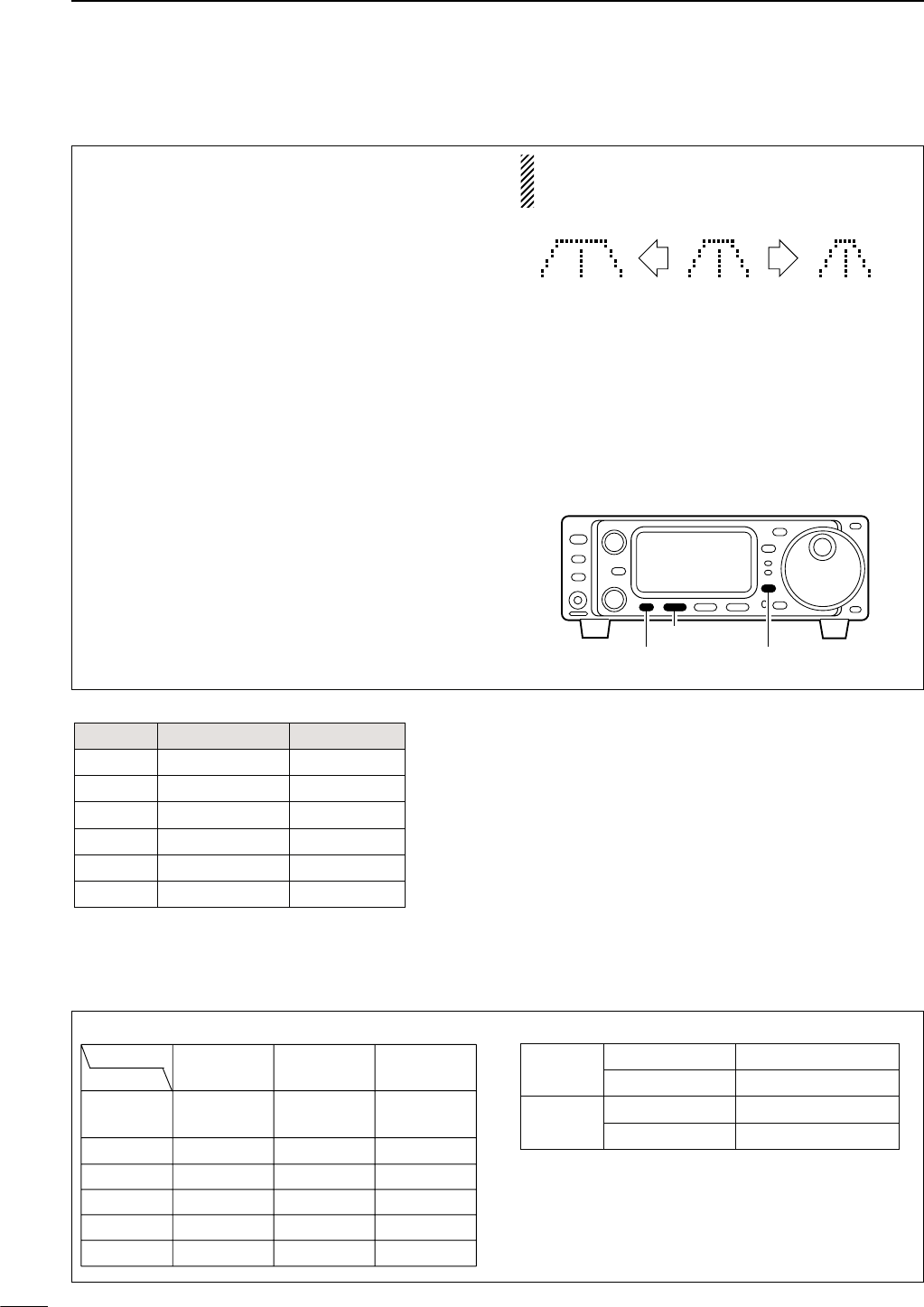
49
5FUNCTION FOR RECEIVE
■Optional filter selection
• Filter variations
*Optional filter.
**Although the FL-96 is not listed on the option list, IC-703 would
take FL-96 as well as other optional filter.
One optional filter can be installed in the IC-703.
Narrow filters help reject interference from adjacent
signals and obtain good selectivity.
Wide filters provide improved audio for SSB operation
when no interfering signals are present.
Consult the table below to select a filter most suitable
for your operating needs.
Narrow filters for AM/FM modes are standard.
FILTER PRESETTING:
After you install a filter (see p. 87 for installation), you
must specify the installed filter in initial set mode (item
“22 OPT. FIL” ; see p. 79).
FILTER ON/OFF:
qSelect M3.
•Push [DISPLAY] once or twice to select M.
• Push [MENU] one or more times to select M3.
wPush [(F-1)FIL] momentarily to select the narrow
filter; push for 1 sec. to select the wide filter.
•ãappears when the narrow filter is selected; çap-
pears when the wide filter is selected.
NOTE:
When selecting the narrow filter (or wide fil-
ter), the graphic passband is changed. (see dia-
gram below)
[DISPLAY][MENU]
[F-1]
Normal
operation
wide is
selected
narrow is
selected
FL-53A* CW, RTTY 250 Hz/–6 dB
CW, RTTY 500 Hz/–6 dB
SSB, CW, RTTY 1.8 kHz/–6 dB
FL-65 SSB, CW, RTTY 2.3 kHz/–6 dB
SSB, CW, RTTY 2.8 kHz/–6 dB
Mode BandwidthName
FL-222*
FL-52A*
FL-96**
SSB, CW, RTTY 3.3 kHz/–6 dBFL-257*
FM Normal Through (15 k)
Narrow CFWS455G (8 k)
AM Normal CFWS455G (8 k)
Narrow FL-65 (2.4 k)
SSB, CW, RTTY
•
Optional filter installation and selection tables
No optional
filter
FL-52A
FL-53A
FL-96
FL-222
FL-257
———
FL-52A (500)
FL-53A (250)
———
FL222 (1.8 k)
———
FL-65 (2.3 k)
FL-65 (2.3 k)
FL-65 (2.3 k)
FL-65 (2.3 k)
FL-65 (2.3 k)
FL-65 (2.3 k)
———
———
———
FL-96 (2.8 k)
———
FL-257 (3.3 k)
Bandwidth Narrow Medium Wide
Filter
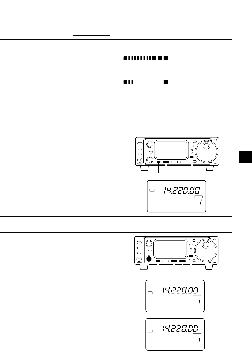
50
5
FUNCTION FOR RECEIVE
This function automatically attenuates beat tones,
tuning signals, etc., even if they are moving. The au-
tomatic notch filter functions in SSB, FM and AM
modes.
qSelect S4 (DSP menu).
•Push [DISPLAY] once or twice to select S.
•Push [MENU] one or more times to select S4.
wPush [(F-1)ANF] to toggle the automatic notch fil-
ter ON and OFF.
• “DSP” and “ANF” appear when the function is ON.
CH
VFO A
P
O
S1
5
5379
20 40
10
60dB
USB
ANFANF
BLANK
DSP
S4 ANF NR NRL
[DISPLAY][MENU]
[F-1]
DANF (Automatic Notch Filter) function
■DSP Functions (may require an optional unit depending on version—see p. 92)
DNR (Noise Reduction) function
This function reduces noise components and picks
out desired signals which are buried in noise. The re-
ceived AF signals are converted to digital signals and
then the desired signals are separated from the noise.
The noise reduction function is available for all oper-
ating modes.
qSelect S4 (DSP menu).
•Push [DISPLAY] once or twice to select S.
•Push [MENU] one or more times to select S4.
wPush [(F-2)NR] to toggle the noise reduction func-
tion ON and OFF.
• “DSP” and “NR” appear when the function is ON.
ePush [(F-3)NRL] to toggle the noise reduction level
indication ON and OFF.
rRotate the [M-CH] control to set the noise reduc-
tion level.
•Set the control for maximum readability. Deep rotation
results in audio signal masking or distortion.
S4 LEVEL 4 NRL
CH
VFO A
P
O
S1
5
5379
20 40
10
60dB
USB
BLANK
DSP
NR
CH
VFO A
P
O
S1
5
5379
20 40
10
60dB
USB
BLANK
DSP
S4 ANF NR NRL
NR
[DISPLAY]
[MENU]
[M-CH] [F-2]
[F-3]
■Peak meter hold
The peak meter hold function freezes the highest dis-
played bar segment in any meter function for about
0.5 sec. so that you can more easily read the meter.
This function can be turned ON and OFF in initial set
mode (item “23 PEAK HOLD” ; see p. 79).
S1 5379204060dB
S1 5379204060dB
Initial reception of a
signal results in an
S-meter reading of
40 dB.
The highest indica-
ted bar remains dis-
played for about 0.5
sec. even when the
signal strength de-
creases.
[EXAMPLE]:
INITIAL SET MODE
5
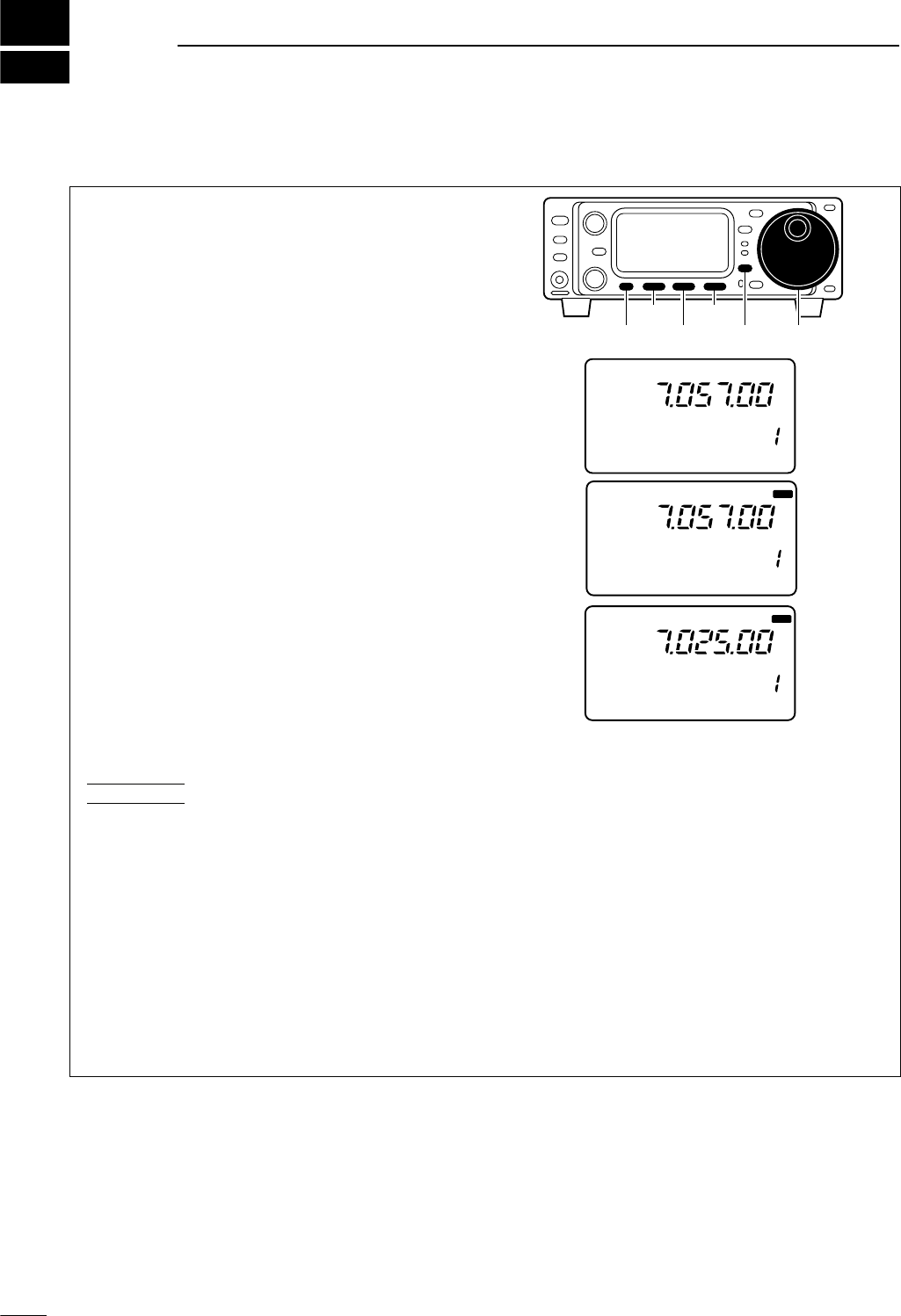
6
51
FUNCTION FOR TRANSMIT
Split frequency operation allows you to transmit and
receive on two different frequencies. Split frequency
operation uses 2 frequencies, one in VFO A and the
other in VFO B.
Following is an example of setting 7.057 MHz, CW
mode in VFO A (for receiving) and 7.025 MHz, CW
mode in VFO B (for transmitting).
qSelect VFO A and set the frequency to 7.057
MHz/CW.
•[(F-2)A/B] is available when M1 appears.
•[(F-3)V/M] is available when M2 appears.
wPush or push and hold [(F-1)SPL] in the M1 dis-
play.
➥Push [SPL]: activates split only.
➥Push and hold [SPL]: activates the quick split
next page.
eTo change the receive frequency, rotate the main
dial; to change the transmit frequency, rotate the
main dial while pushing [(F-3)XFC].
•The transmit frequency can be monitored while push-
ing [(F-3)XFC].
•Split operation is now set for receive on 7.057 MHz/CW
and transmit on 7.025 MHz/CW.
To exchange the transmit and receive frequencies,
push [(F-2)A/B] in M1.
CONVENIENT
The G3 display conveniently shows the transmit fre-
quency during split frequency operation and pushing
[(F-3)Ñ] allows you to change the transmit frequency.
• Split lock function
The split lock function is convenient for changing only
the transmit frequency. Otherwise, accidentally re-
leasing the [(F-3)XFC] switch while rotating the main
dial changes the receive frequency. The split lock’s ef-
fectiveness can be selected in initial set mode (item
“25 SPLIT LOCK”) for both receive and transmit
frequencies; or only the receive frequency. (p. 80)
CH
P
O
S1
5
5379
20 40
10
60dB
CW
M1 SPL A/B XFC
SPL
VFO B
CH
VFO A
P
O
S1
5
5379
20 40
10
60dB
CW
M1 SPL A/B XFC
SPL
CH
VFO A
P
O
S1
5
5379
20 40
10
60dB
CW
SPL
M1 SPL A/B XFC
[DISPLAY] Main dial[MENU]
[F-1]
[F-2]
[F-3]
■Split frequency operation
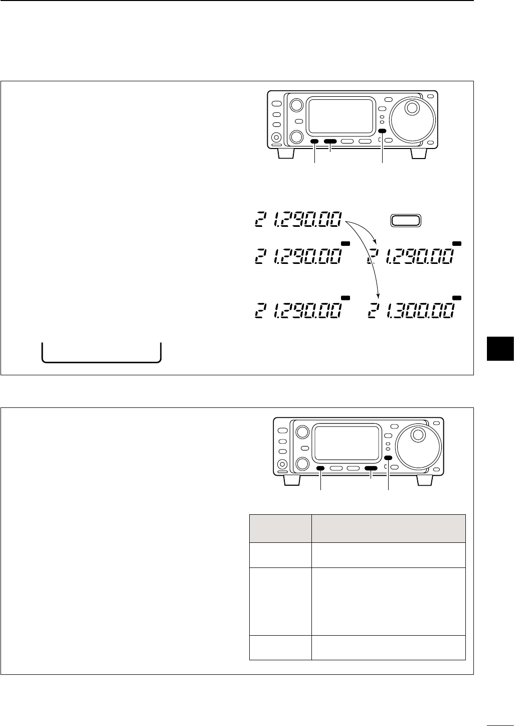
52
6
FUNCTION FOR TRANSMIT
DQuick split function
In M1, when you push [(F-1)SPL] for 1 sec., split fre-
quency operation is turned ON and VFO B is auto-
matically changed according to the plus/minus
pre-programmed shift frequency set in initial set mode
(or equalized when 0 kHz is programmed as the split
shift frequency). This shortens the time needed to
start split frequency operation—great for DX’ing.
The quick split function is ON by default. If desired, it
can be turned OFF in initial set mode (p. 79). In this
case, pushing [(F-1)SPL] for 1 sec. has the same ef-
fect as pushing [(F-1)SPL] momentarily as in normal
split operation.
PROGRAMMING SPLIT SHIFT FREQUENCY (p.80)
qPush [POWER] to turn power OFF.
wWhile pushing [LOCK], push [POWER] to turn
power ON and enter initial set mode.
eSelect “26 SPL OFFSET” using [MENU], [M-
CH] or the [Y]/[Z] keys, then rotate the main dial
to select the desired split offset.
•The split offset can be selected from –9.999 MHz to
+9.999 MHz.
VFO A
VFO A
SPL
SPL SPL
SPL
VFO A
VFO B
VFO B
No shift frequency is programmed.
+10 kHz is programmed as a shift
frequency.
Push for 1 sec.
SPL
F-1
[DISPLAY][MENU]
[F-1]
26 SPL OFFSET
■Meter selection
The bar meter in the function display acts as an
S-meter for relative signal strength during receiving
and can be selected for one of three types during
transmitting.
qSelect M3.
•Push [DISPLAY] once or twice to select M.
• Push [MENU] one or more times to select M3.
wPush [(F-3)MET] one or more times to select the
desired meter function.
• The display indication changes as in the table at right.
[DISPLAY][MENU]
[F-3]
DISPLAY
INDICATION MEASUREMENT
Po Indicates the relative RF output power.
ALC
Indicates the ALC level. When the
meter movement shows the input signal
level exceeds the allowable level, the
ALC limits the RF power. In such cases,
reduce the microphone gain (see
above).
SWR Indicates the SWR over the transmis-
sion line.
6
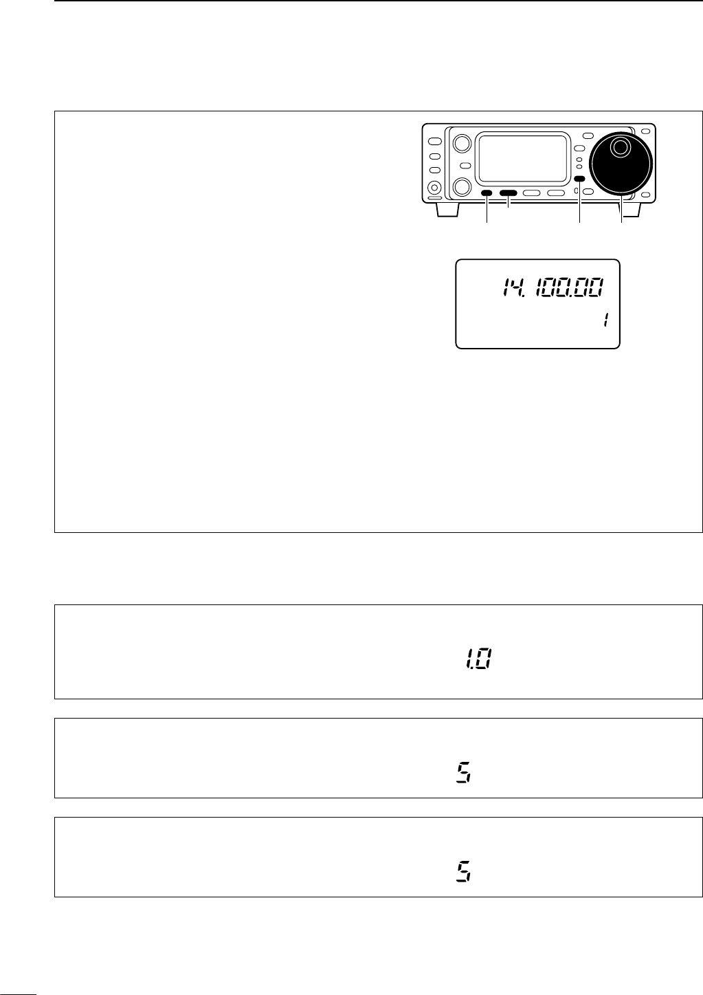
53
6FUNCTION FOR TRANSMIT
The VOX (Voice-operated Transmission) function tog-
gles between transmit and receive with your voice.
This function provides an opportunity to input log en-
tries into your computer, etc., while operating.
qSelect M4.
• Push [DISPLAY] once or twice to select M.
• Push [MENU] one or more times to select M4.
wPush [(F-1)VOX] to toggle the VOX function ON
and OFF.
• “VOX” appears when the function is ON.
ePush [(F-1)VOX] for 1 sec. to enter the VOX set
mode (below), then set the ‘VOX delay,’ ‘VOX gain’
and ‘ANTI-VOX’ if desired.
rSelect “VOX DELAY” in VOX set mode.
•Push [MENU] one or more times to select V1.
•While speaking into the microphone, adjust ‘VOX
DELAY’ as desired.
tSelect “VOX GAIN” in VOX set mode.
•Push [MENU] one or more times to select V2.
•While speaking into the microphone, adjust ‘VOX GAIN’
until the transceiver is transmitting.
ySelect “ANTI VOX” in VOX set mode.
•Push [MENU] one or more times to select V3.
•If the receive audio from the speaker toggles the trans-
ceiver to transmit during receive, adjust the ‘ANTI-VOX’
to the point where it has no effect.
uPush [DISPLAY] to exit VOX set mode.
[DISPLAY][MENU]
[F-1]
Main dail
R
LSB
CH
VFO A
P
O
S1
5
5379
20 40
10
60dB
USB CW R
TT
Y
AM WFM
M4 VOX COM AGC
VOX COM
■VOX operation
While M4 is selected in SSB/AM/FM modes, push
[(F-1)VOX] for 1 sec. to enter the VOX set mode.
DVOX set mode
V1 VOX DELAY
This item adjusts the VOX (Voice-activated Transmit)
delay time. The delay time can be adjusted from 0 to
2 sec. in 0.1 sec. steps.
The default is 1.0 seconds.
USB
V2 VOX GAIN
This item adjusts the VOX gain for the VOX (voice ac-
tivated transmit) function.
The default is 5.
USB
V3 ANTI VOX
This item adjusts the ANTI-VOX gain for the VOX
(voice activated transmit) function.
The default is 5.
USB
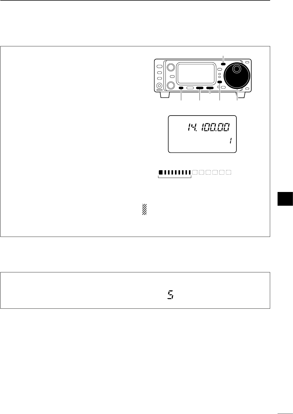
54
6
FUNCTION FOR TRANSMIT
The IC-703 has a built-in, low distortion speech com-
pressor circuit. This circuit increases your average
talk power in SSB mode and is especially useful for
DX’ing when the receiving station is having difficulty
copying your signal.
qSelect USB or LSB mode.
wSelect the mic gain display in quick set mode.
• Push [DISPLAY] for 1 sec.
•Push [MENU] one or more times to select “Q2 MIC
GAIN.”
•The ALC meter is selected automatically when operat-
ing in SSB mode.
eAdjust the mic gain.
•While transmitting at your normal voice level, the ALC
meter should read at about the middle of the ALC zone.
• Be sure the mic gain is in the range of 2 to 5.
rSelect the ALC meter.
• Push [DISPLAY] once or twice to select M.
•Push [MENU] one or more times to select M3, then
push [(F-3)MET] one or more times to select “ALC.”
tPush [MENU] one or more times to select M4.
yPush [(F-2)COM] to turn the speech compressor
function ON.
• “COM” appears.
uPush [(F-2)COM] for 1 sec. to enter the compres-
sion level set mode (below).
iRotate the main dial to set the speech compression
level.
NOTE:
When the ALC meter peaks above the ALC
zone, your transmitted voice may be distorted.
ALC
Adjust ‘COMP LEVEL’ so that the ALC meter
reads within the ALC zone.
ALC zone
[DISPLAY][MENU]
[MODE]
Main dail[F-2]
[F-3]
R
LSB
CH
VFO A
P
O
S1
5
5379
20 40
10
60dB
USB CW R
TT
Y
AM WFM
M4 VOX COM AGC
VOX COM
■Speech compressor
While M4 is selected in SSB/AM modes, push
[(F-2)COM] for 1 sec. to enter the compression level set
mode.
DCompression level set mode
C1 COMP LEVEL
This item adjusts the speech compression level. The
speech compression level can be adjusted from 0 to
10.
The default is 5.
USB
6
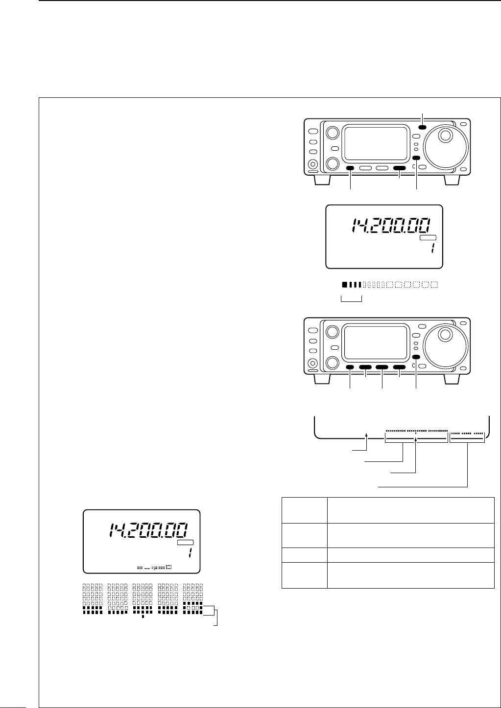
55
6FUNCTION FOR TRANSMIT
The IC-703 has a built-in circuit for measuring an-
tenna SWR—no external equipment or special ad-
justments are necessary.
The IC-703 can measure SWR in 2 ways:
(A) Spot measurement; or (B) Plot measurement.
(A) Spot measurement
qConfirm that the output power is over 5 W.
wPush [MENU] one or more times to select M3.
ePush [(F-3)MET] to select the SWR meter.
rPush [MODE] one or more times to select CW or
RTTY operation.
•Key down or push [PTT] to transmit; then read the ac-
tual SWR from the meter:
➠≤1.5 well matched antenna
➠>1.5 check antenna or cable connection, etc.
(B) Plot measurement
Plot measurement allows you to measure the SWR
over an entire band.
qConfirm that the output power is over 5 W.
wPush [DISPLAY] once or twice to select G.
ePush [MENU] one or more times to select G2.
rSet the center frequency for the SWR to be mea-
sured.
tPush and hold [(F-1)10k] one or more times to se-
lect the desired frequency pitch.
yPush and hold [(F-2)] one or more times to select
the desired step.
uAfter selecting the desired pitch and step, push
[(F-3)STR] to measure the SWR.
• RTTY mode is selected automatically.
iPush and hold [PTT] to display the SWR in a bar
graph readout.
oWhen [PTT] is released, the frequency marker and
frequency indication move to the next frequency to
be measured.
!0 Repeat steps iand oto measure SWR over the
entire frequency range.
!1 When the measured SWR is less than 1.5, the an-
tenna is well matched.
G2 10k STR
Frequency span
Step bar indication
Frequency indication mark
Measure start indicator
[DISPLAY][MENU]
[F-3]
[F-1]
[F-2]
CH
VFO A
SWR
S1
1 1.5 2 3
5379
20 40 60dB
CW
BLANK
SWR 1 1.5 2 3
The best match is in this range.
∞
∞
M3 FIL NB MET
[DISPLAY][MENU]
[F-3]
[MODE]
The antenna is well matched in this range
CH
VFO A
P
O
S1
5
5379
20 40
10
60dB
BLANK
G2 50k STR
4
.
0
3
.
5
3
.
0
2
.
5
2
.
0
1
.
5
1
.
0
R
TT
Y
■SWR
DMeasuring SWR
Span Push [F-1] for 1 sec. to change the se-
lected span.
Step bar Push [F-2] to change the step bar (3, 5,
7 or 9 steps are available.
Marker Indicates the currently active step bar.
Start Flashes while the SWR is being mea-
sured.
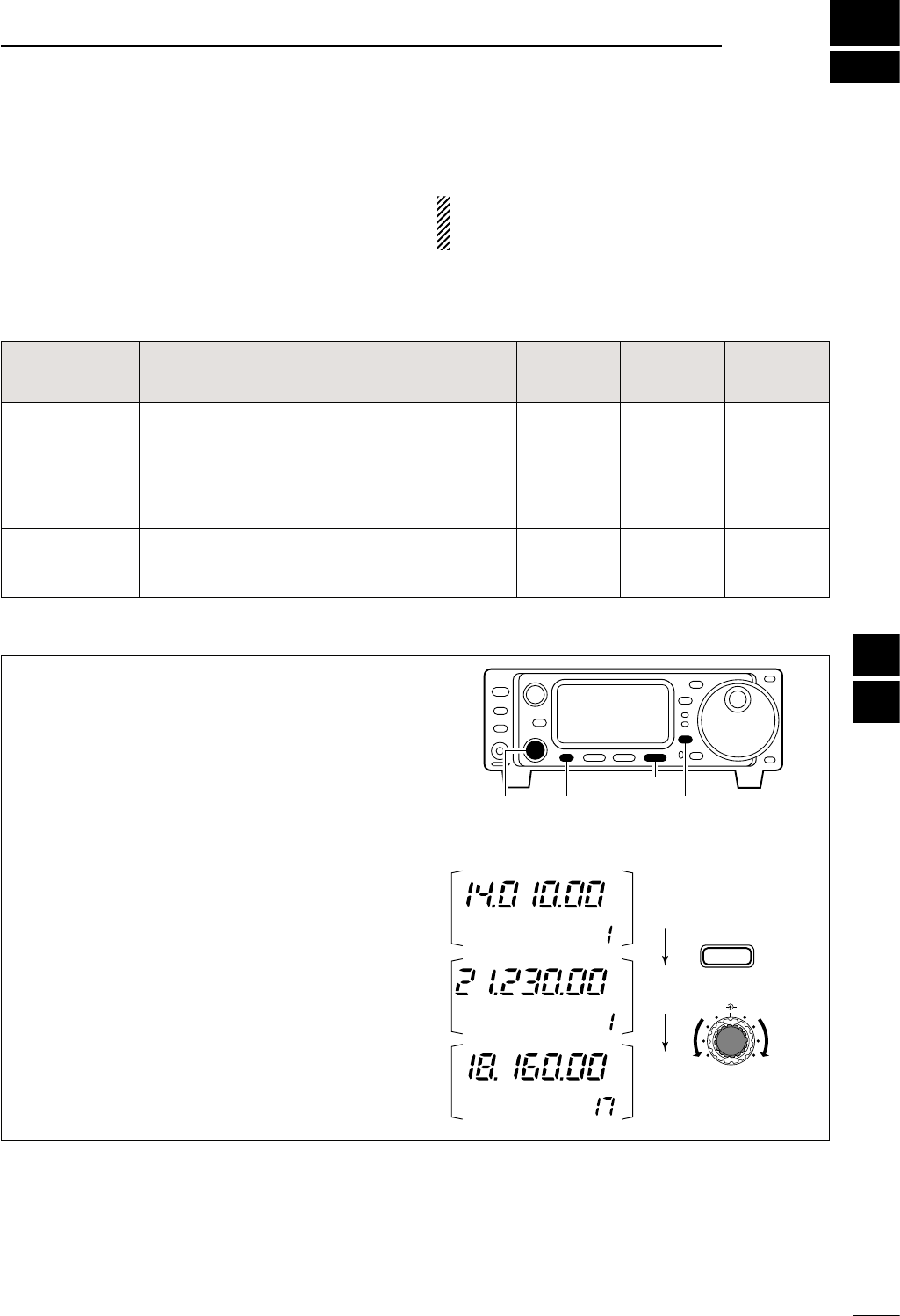
7
56
MEMORY OPERATION
■Memory channels
The transceiver has 105 memory channels (includes 6
scan edge channels). Memory mode is useful for
quickly changing to often-used frequencies.
All 105 memory channels are tuneable which means
the programmed frequency can be tuned temporarily
with the main dial, etc., in memory mode.
qSelect M2 functions.
• Push [DISPLAY] once or twice to select M.
• Push [MENU] one or more times to select M2.
wPush [(F-3)V/M] to select memory mode.
eRotate [M-CH] to select the desired memory chan-
nel.
•All memory channels including blank channels can be
selected.
• [UP]/[DN] on the microphone changes the frequency.
rTo return to VFO mode, push [(F-3)V/M] again.
CW
CH
VFO A
[EXAMPLE]: Selecting memory channel 17.
V/M
F-3
USB
CH
MEMO
SPLIT
CH
MEMO
USB
M-CH SHIFT
[DISPLAY][MENU][M-CH]
[F-3]
■Memory channel selection
NOTE:
During split frequency operation, pro-
grammed memory contents can be called up to the
SUB readout (dot matrix portion of the display).
MEMORY
CHANNEL
MEMORY
CHANNEL
NUMBER
CAPABILITY TRANSFER
TO VFO
OVER-
WRITING CLEAR
Regular
(split memory) 1–99
Independent transmit and receive
frequencies and one mode in each
memory channel.
In addition, tone frequencies can
also be stored for repeater use.
Yes Yes Yes
Scan edges 1A–3B
(3 pairs)
One frequency and one mode in
each memory channel as scan
edges for programmed scan.
Yes Yes No
6
7
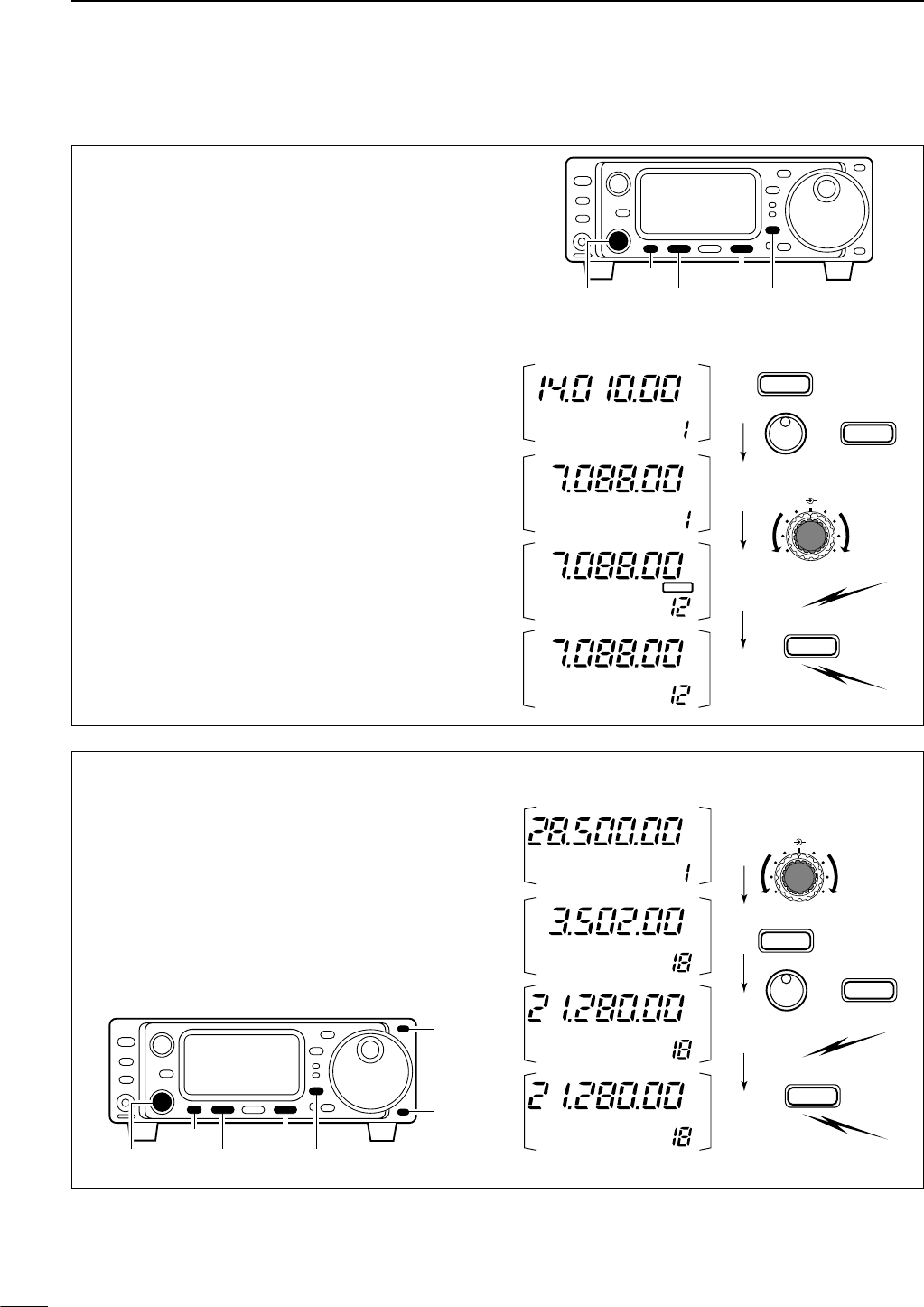
57
7MEMORY OPERATION
• Programming in VFO mode
qSelect M2 functions.
• Push [DISPLAY] once or twice to select M.
•Push [MENU] one or more times to select M2.
wSet the desired frequency and operating mode in
VFO mode.
•If you want to program the split frequency function, pro-
gram both receive and transmit frequencies into VFO A
and B, then turn ON the split function.
•If you want to program a repeater function, set a tone
frequency (pgs. 44, 45) in addition to the receive/trans-
mit frequencies.
eRotate [M-CH] to select the desired memory chan-
nel.
•
Select memory mode to confirm the contents, if desired.
•“}” appears if the selected memory channel is a
blank channel (and does not have contents).
rPush [(F-1)MW] for 1 sec. to program the displayed
frequency and operating mode into the memory
channel.
To check the programmed contents, push [(F-3)V/M]
to select memory mode.
CW
CH
VFO A
[EXAMPLE]: Programming 7.088 MHz/LSB into ch 12.
TS
MODE
MW
F-1
LSB
BLANK
SPLIT
CH
VFO A
LSB
CH
VFO A
LSB
CH
VFO A
Push for
1 sec.
M-CH SHIFT
[DISPLAY]
[MENU]
[M-CH]
[F-3]
[F-1]
■Memory programming
• Programming in memory mode
qSelect M2 functions.
• Push [DISPLAY] once or twice to select M.
•Push [MENU] one or more times to select M2.
wSet the desired frequency and operating mode.
ePush [(F-3)V/M] to select memory mode, then se-
lect the desired memory channel with [M-CH].
•Push [Y]/[Z] when you want to program blank chan-
nels.
rPush [(F-1)MW] for 1 sec. to program the displayed
frequency and operating mode into the memory
channel.
CH
[EXAMPLE]:
Programming 21.280 MHz/USB into
ch 18.
TS
MODE
MW
F-1
SPLIT
Push for
1 sec.
CH
MEMO
USB
CH
MEMO
USB
CH
MEMO
CW
CH
MEMO
USB
M-CH SHIFT
[DISPLAY]
[MENU]
[M-CH]
[F-3]
[F-1]
[Y]
[Z]
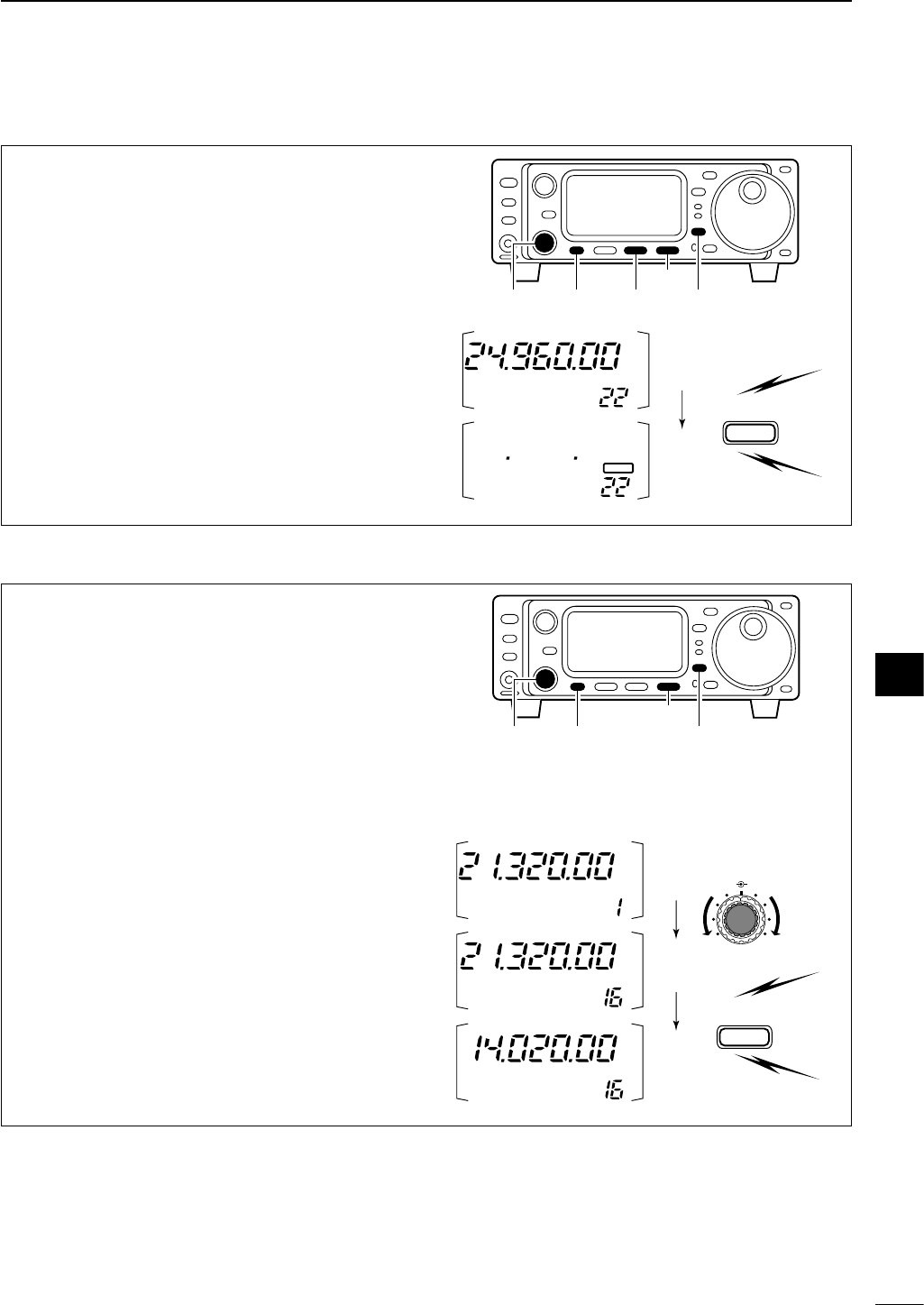
58
7
MEMORY OPERATION
Any unnecessary memory channels can be cleared.
The cleared memory channels become blank chan-
nels.
qSelect M2 functions.
• Push [DISPLAY] once or twice to select M.
• Push [MENU] one or more times to select M2.
wPush [(F-3)V/M] to select memory mode.
eRotate [M-CH] to select a memory channel to be
cleared.
rPush [(F-2)MCL] for 1 sec. to clear the contents.
•The programmed frequency and operating mode dis-
appear and “}” appears.
tTo return to VFO mode, push [(F-3)V/M] again.
MCL
F-2
SPLIT
Push for
1 sec.
CH
MEMO
USB
CH
MEMO
BLANK
[DISPLAY][MENU][M-CH]
[F-3]
[F-2]
■Memory clearing
■Frequency transferring
The frequency and operating mode can be trans-
ferred from memory mode to VFO mode.
qSelect M2 functions.
• Push [DISPLAY] once or twice to select M.
• Push [MENU] one or more times to select M2.
wSelect VFO mode with [(F-3)V/M].
eSelect a memory channel with [M-CH].
•Select memory mode to confirm the memory channel’s
contents, if desired; then return to VFO mode.
•“}” appears if the selected memory channel is a
blank channel (and does not have contents). In this
case transferring is not possible.
rPush [(F-3)V/M] for 1 sec. to transfer the frequency
and operating mode.
•Transferred frequency and operating mode appear in
the display.
V/M
F-3
SPLIT
Push for
1 sec.
[EXAMPLE]: Transferring contents of memory 16.
Operating frequency: 21.320 MHz/USB (VFO)
Contents of memory 16: 14.020 MHz/CW
CH
VFO A
USB
CH
VFO A
USB
CH
VFO A
CW
M-CH SHIFT
[DISPLAY][MENU][M-CH]
[F-3]
7
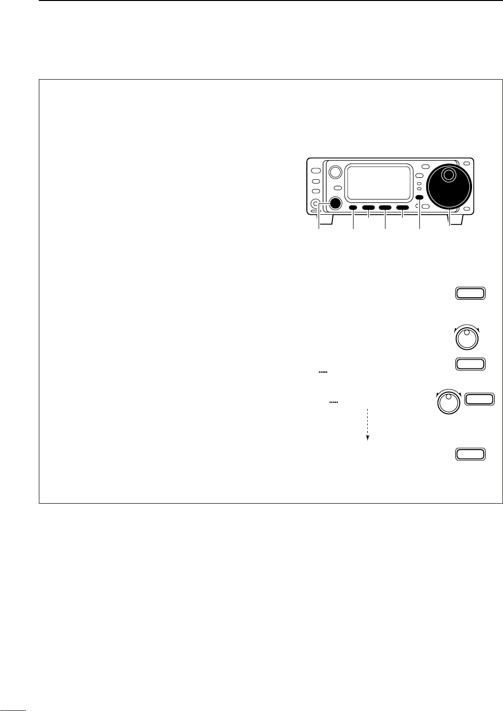
59
7MEMORY OPERATION
■Memory names
All memory channels (including scan edges) can be
tagged with alphanumeric names of up to 9 charac-
ters each.
All common keyboard characters (ASCII characters
33 to 126) can be used, including numerals and punc-
tuation marks.
•Calling up memory names
qSelect the G4 display.
•Push [DISPLAY] once or twice to select G.
•Push [MENU] one or more times to select G4.
wSelect a memory channel with [M-CH].
•Editing (programming) memory names
qCall up the desired memory (channel) name as
above.
wPush [(F-3)É] to enter memory name edit mode.
•“[DEL]” appears briefly, then a cursor blinking under
the first character position.
eRotate the main dial to select the desired charac-
ter, then advance the cursor position.
•Pushing [(F-3)Ç] moves the cursor to the right; [(F-1)Å]
moves the cursor to the left.
• Pushing [(F-2)] deletes the character.
rRepeat this procedure until all desired characters
have been selected.
tPush [(MENU)Ä] to exit memory name edit mode.
•The G4 display re-appears and the programmed mem-
ory name is displayed.
G4 memory name
G4
G4 Repeater É
ÄÅÖ
[DEL]
É
F-3
Ç
F-3
Ç
F-3
Ä
MENU
ÄÅR
Ç
Ç
ÄÅRe Ç
ÄÅRepeaterÖÇ
É
[DISPLAY][M-CH]
[F-3]
[F-1]
Main dial
[MANU] [F-2]
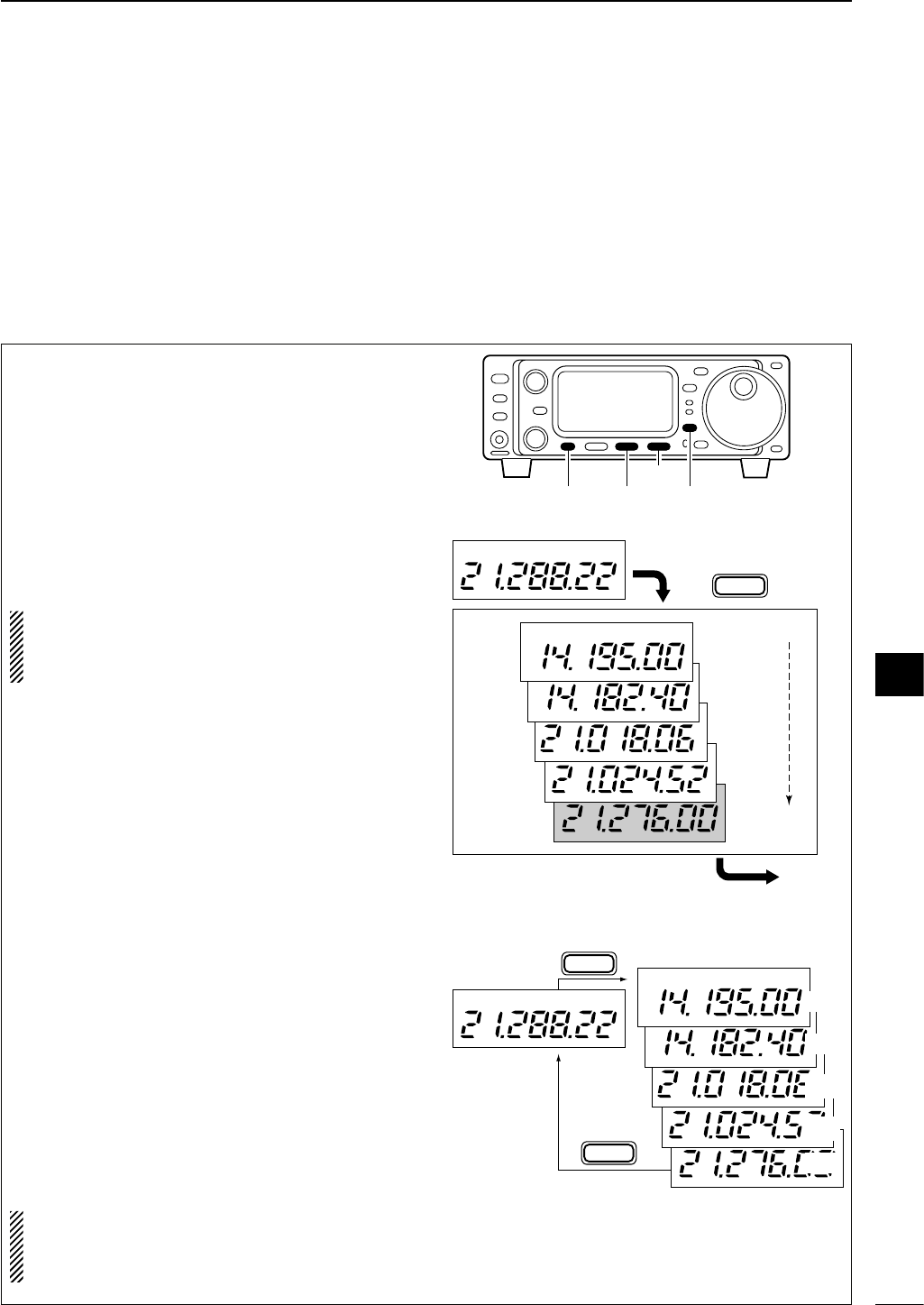
•Writing frequencies and operating modes
into memo pads
qSelect the S1 display.
• Push [DISPLAY] once or twice to select S.
• Push [MENU] one or more times to select S1.
wPush [(F-2)MPW] to program the frequency into a
memo pad.
When you write a 6th frequency and operating mode,
the oldest written frequency and operating mode are
automatically erased to make room for the new set-
tings.
NOTE:
Each memo pad must have its own unique
combination of frequency and operating mode;
memo pads having identical settings cannot be
written.
•Calling up a frequency from a memo pad
You can simply call up the desired frequency and op-
erating mode of a memo pad by pushing [(F-3)MPR]
in the S1 display.
• Make sure S1 is selected in advance.
• Both VFO and memory modes can be use.
• The frequency and operating mode are called up, starting
from the most recently written.
When you call up a frequency and an operating mode
from memo pads with [(F-3)MPR], the previously dis-
played frequency and operating mode are automati-
cally stored in a temporary pad. The frequency and
operating mode in the temporary pad can be recalled
by pushing [(F-3)MPR] one or more times.
NOTE:
If you change the frequency or operating
mode called up from a memo pad, the frequency
and operating mode in the temporary pad are
erased.
Displayed frequency and mode
Push
Newest
MP5
MP4
MP3
MP2
MP1
The oldest written frequency
and mode are erased.
Oldest
MPW
F-2
USB
USB
USB
USB
USB
USB
[DISPLAY]
[F-3]
[MANU] [F-2]
60
7
MEMORY OPERATION
VFO or
MEMORY
mode
MEMO PADS
MPR
F-3
MPR
F-3
USB
USB
USB
USB
USB
USB
MP5
MP4
MP3
MP2
MP1
■Memo pads
The transceiver has a memo pad function to store fre-
quency and operating mode for easy write and recall.
The memo pads are separate from memory channels.
The default number of memo pads is 5, however, this
can be increased to 10 in initial set mode if desired
(p. 80).
Memo pads are convenient when you want to memo-
rize a frequency and operating mode temporarily, such
as when you find a DX station in a pile-up or when a
station is busy for a long time and you want to tem-
porarily search for other stations.
Use the transceiver’s memo pads instead of relying on
hastily scribbled notes that are easily misplaced.
7
8
61
SCAN OPERATION
■Scan types
■Preparation
• Channels
For programmed scan: Program scan edge frequen-
cies into scan edge memory channels 1A and 1B.
(p. 57)
For memory scan: Program 2 or more memory chan-
nels except scan edge memory channels.
For memory select scan: Designate 2 or more mem-
ory channels as select memory channels—select a
memory channel, then push [(F-2)SEL] in the S2 dis-
play (memory mode) to designate the channel as a se-
lect memory channel.
For priority watch: Program 1 memory channel to be
watched.
• Scan resume ON/OFF
You can select the scan to resume or cancel when de-
tecting a signal, in initial set mode, item “27 SCAN
RESUME”. Scan resume ON/OFF must be set before
operating a scan. See p. 80 for ON/OFF setting and
scan resume condition details.
•Scan speed
Scan speed can be selected from 2 levels, high or low,
in initial set mode. See p. 80 for details.
• Squelch condition
PROGRAMMED SCAN
Repeatedly scans between two scan edge frequencies
(scan edge memory channels 1A and 1B).
This scan operates in VFO mode.
SELECTED MEMORY SCAN
Repeatedly scans all selected memory channels.
PRIORITY WATCH
Checks for signals on a memory while operating on a
VFO frequency.
This scan operates in memory mode.This scan operates in memory mode.
This scan operates in VFO mode.
Scan
Scan edge 1A or 1B Scan edge 1B or 1A
Jump
Mch 1 Mch 5
Memory
channel
VFO
frequency
Mch 2 Mch 3 Mch 4
Mch 6Mch 7Mch 99
MEMORY SCAN
Repeatedly scans all programmed memory channels.
Mch 1 Mch 5
Mch 2 Mch 3 Mch 4
Mch 6Mch 7Mch 99
BLANK
S(select)
S(select)S(select)
S(select) S(select)
S(select)
S(select)S(select)
S(select) S(select)
BLANK
SCAN
STARTS
WITH
PROGRAMMED
SCAN
MEMORY SCANS
PRIORITY WATCH
SQUELCH
OPEN
The scan continues
until it is stopped man-
ually, and does not
pause even if it de-
tects signals.
This is not applicable
when the scan re-
sume is OFF and a
programmable step
(more than 1 kHz) is
selected.
Scan pauses on each
channel when the
scan resume is ON;
not applicable when
OFF.
SQUELCH
CLOSED
Scan stops when detecting a signal.
If you set scan resume ON in initial set mode,
the scan pauses for 10 sec. when detecting a
signal, then resumes. When a signal disap-
pears while scan is paused, scan resumes 2
sec. later.
62
8
SCAN OPERATION
qSelect VFO mode.
wSelect the desired operating mode.
•The operating mode can also be changed while scan-
ning.
eSet [SQL] open or closed.
• See page a left for squelch condition.
rSelect S2.
• Push [DISPLAY] once or twice to select S.
•Push [MENU] one or more times to select S2.
tPush [(F-1)SCN] to start the scan.
• Decimal point blinks while scanning.
yWhen the scan detects a signal, the scan turns
OFF, pauses or ignores it depending on the re-
sume setting and the squelch condition.
•During scan [TS] can be used only when resume is ON.
uTo cancel the scan push [(F-1)SCN].
NOTE:
If the same frequencies are programmed
into the scan edge memory channels 1A and 1B,
programmed scan does not start.
CH
VFO A
P
O
S1
5
53792040
10
60dB
USB
S2 SCN PRI V/M
Select
VFO mode
F-1 then push [(F-1)SCN]
[DISPLAY]
[F-1]
[MANU][SQL]
■Programmed scan operation
qSelect memory mode.
wClose the squelch with [SQL].
eSelect S2.
• Push [DISPLAY] once or twice to select S.
•Push [MENU] one or more times to select S2.
rPush [(F-1)SCN] to start the scan.
• Decimal point blinks while scanning.
tWhen the scan detects a signal, the scan stops or
pauses depending on the resume setting.
yTo cancel the scan push [(F-1)SCN].
NOTE:
Two or more memory channels must be
programmed for memory scan to start.
S2 SCN SEL V/M
Select
memory mode
F-1 then push [(F-1)SCN]
CH
MEMO
P
O
S1
5
53792040
10
60dB
USB
[DISPLAY]
[F-1]
[MANU][SQL]
■Memory scan operation
8
63
8SCAN OPERATION
qSelect VFO mode, then set a frequency.
wClose the squelch with [SQL].
eSet the desired memory channel as the watching
channel.
rSelect S2.
• Push [DISPLAY] once or twice to select S.
•Push [MENU] one or more times to select S2.
tPush [(F-2)PRI] to start the priority watch.
• Decimal point blinks while scanning.
yWhen the scan detects a signal, the scan pauses
for 10 sec. or until the signal disappears, depend-
ing on the resume setting.
uTo cancel the scan push [(F-2)PRI].
NOTE:
The paused condition when detecting a sig-
nal differs depending on the scan resume condi-
tion. (p 80)
resume on: pauses for 10 sec.
resume off: pauses until the signal disappears.
S2 SCN PRI V/M
Select
VFO mode
Select watching
channel
F-2 Push [(F-2)PRI].
CH
P
O
S1
5
53792040
10
60dB
USB
VFO A
[DISPLAY][MANU] [F-2][SQL]
qSelect memory mode.
wClose the squelch with [SQL].
eSelect S2.
• Push [DISPLAY] once or twice to select S.
•Push [MENU] one or more times to select S2.
rPush [(F-1)SCN] to start the memory scan.
• Decimal point blinks while scanning.
tPush [(F-2)SEL] to change the memory scan to se-
lect memory scan.
•Push [(F-2)SEL] for 2 sec. to clear all select memory
channels.
yWhen the scan detects a signal, the scan stops or
pauses depending on the resume setting.
uTo cancel the scan push [(F-1)SCN].
NOTE:
Two or more memory channels must be
designated as select memory channels for select
memory scan to start (see p. 61).
S2 SCN SEL V/M
Select
memory mode
Designate
“S.”
F-1 F-2
Push [(F-1)SCN], then [(F-2)SEL].
CH
S
MEMO
P
O
S1
5
53792040
10
60dB
USB
[DISPLAY]
[F-1]
[MANU] [F-2][SQL]
■Select memory scan operation
■Priority watch
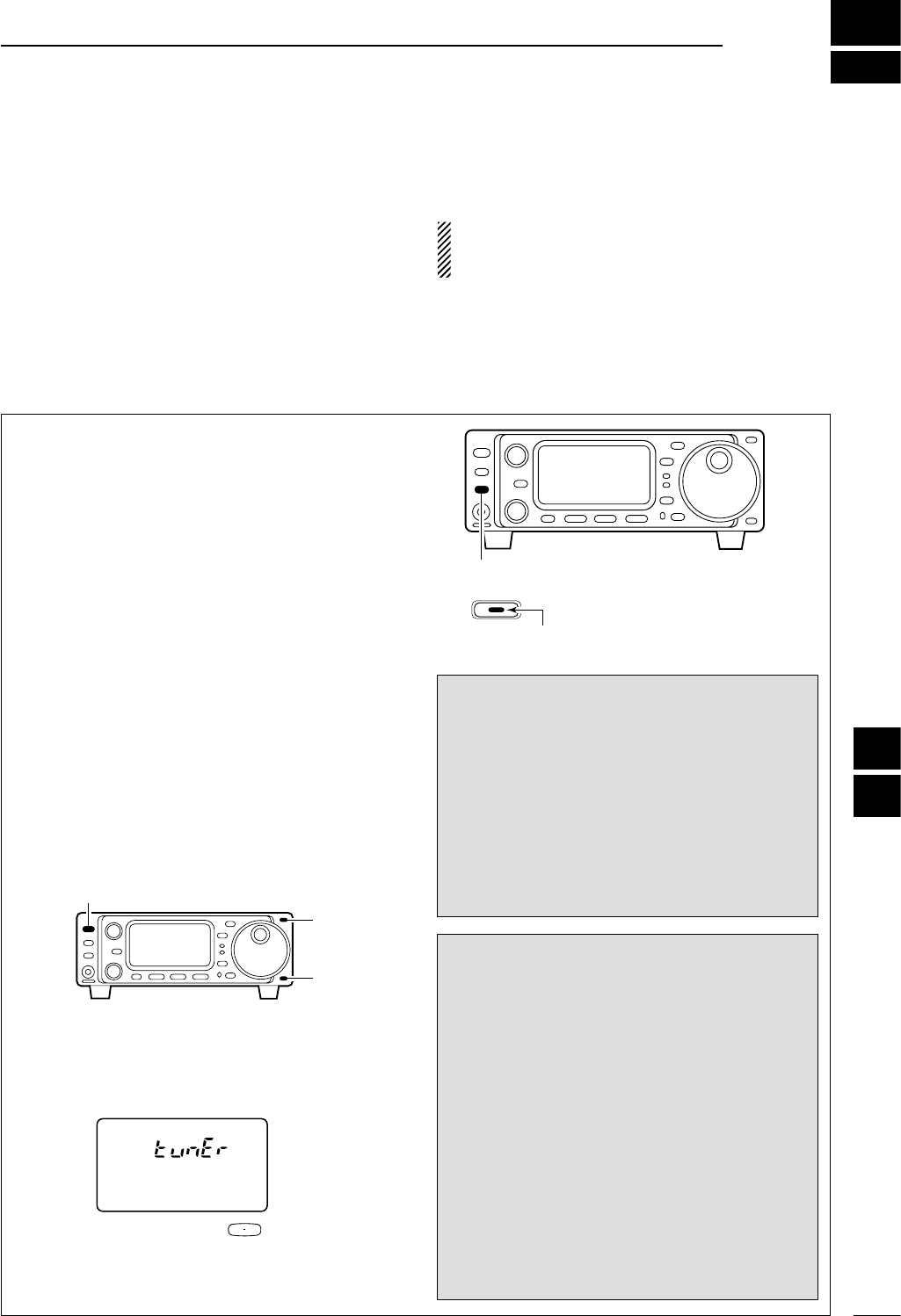
9
64
ANTENNA TUNER OPERATION
The internal automatic antenna tuner matches the
transceiver to the connected antenna automatically.
Once the tuner matches an antenna, the latching relays
combination are memorized as a preset point for each
frequency range (100 kHz steps). Therefore, when you
change the frequency range, the latching relays are au-
tomatically preset to the memorized combination.
CAUTION: NEVER transmit with the tuner ON
when no antenna is connected. This will damage
the transceiver. Be careful of the antenna selection.
Push [TUNER] to turn the internal antenna tuner
ON. The antenna is tuned automatically when the
antenna SWR is higher than 1.5:1.
•When the tuner is ON, the ‘TUNER’ indicator lights red.
• MANUAL TUNING
Push [TUNER] for 1 sec., to start manual tuning.
•A side tone is emitted and ‘TUNER’ indicator blinks
while tuning.
•If the tuner cannot reduce the SWR to less than 1.5:1
after 20 sec. of tuning, the ‘TUNER’ indicator goes out.
• PTT TUNER START
The tuner is always tuned when the PTT is pushed
after the frequency is changed (more than 1% from
last-tuned frequency). This function removes the
“push and hold [TUNER]” operation and activates for
the first transmission on a new frequency.
This function can be turned ON in initial set mode
(p. 81).
• TUNER RESET
qMake sure the transceiver power is OFF.
wWhile pushing [Y] and [Z], push [POWER] to turn
power ON.
•“CLEAR ? OK” appears as shown below.
eRotate main dial to select tuner reset.
rThen Push [F-3] for 1 sec to start tuner resetting.
• The memorized tuner settings are reset.
[TUNER]
TUNER
Lights to indicate internal tuner is activated.
CLEAR ? OK
F 3
[POWER]
[Y]
[Z]
DIf the tuner cannot tune the antenna
Check the following and try again:
• the antenna connection and feedline.
•the unaltered antenna SWR. (Less than 3:1 for HF bands;
Less than 2.5:1 for 50 MHz band)
• the power source voltage/capacity.
If the tuner cannot reduce the SWR to less than
1.5:1 after checking the above, perform the follow-
ing:
• repeat manual tuning several times.
•tune with a 50 Ωdummy load and re-tune the antenna.
• turn power OFF and ON.
•adjust the antenna cable length.
(This is effective for higher frequencies in some cases.)
•Some antennas, especially for low bands, have a nar-
row bandwidth. These antennas may not be tuned at
the edge of their bandwidth, therefore, tune such an
antenna as follows:
NOTES:
•The internal antenna tuner can tune the HF to 50 MHz
bands.
•NEVER transmit without an antenna properly connected
to antenna port in use.
•If the SWR is higher than about 1.5:1 when tuning
above 100 kHz on an antenna’s preset point, push
[TUNER] for 1 sec. to start manual tuning.
•When strong impact is applied, the internal tuner may
not work properly caused by the latching relay is off po-
sition. In this case, push [POWER] momentarily to reset
the all latching relays while transceiver power is ON.
DInternal antenna tuner
DTuner operation
■Antenna tuner operation
8
9
65
9ANTENNA TUNER OPERATION
The AT-180 automatic antenna tuner matches the IC-
703 to the connected antenna automatically. Once the
tuner matches an antenna, the variable capacitor an-
gles are memorized as a preset point for each fre-
quency range (100 kHz steps). Therefore, when you
change the frequency range, the variable capacitors
are automatically preset to the memorized point.
CAUTION: NEVER transmit with the tuner ON
when no antenna is connected. This will damage
the transceiver. Be careful of the antenna selection.
•The AT-180 can match both HF and 50 MHz bands.
However, operation is different for the HF and 50
MHz bands.
TUNER OPERATION
• For the HF band:
Push [TUNER] to turn the tuner ON. The antenna is
tuned automatically during transmission when the an-
tenna SWR is higher than 1.5:1.
• When the tuner is OFF, the [TUNER] light goes out.
• For the 50 MHz band:
Push [TUNER] for 1 sec. to tune the antenna. If the
[TUNER] light flashes slowly while transmitting, push
and hold [TUNER] for 1 sec. again to re-tune the an-
tenna.
MANUAL TUNING
During SSB operation on HF bands at low voice lev-
els, the AT-180 may not be tuned correctly. In such
cases, manual tuning is helpful.
Push [TUNER] for 1 sec. to start manual tuning.
•CW mode is selected, a side tone is emitted, and the
[TUNER] light flashes; then, the previous mode is selected.
If the tuner cannot reduce the SWR to less than 1.5:1
after 20 sec. of tuning, the [TUNER] light goes out. In
this case, check the following:
• the antenna connection and feedline
• the antenna SWR (p. 55; meter function)
Through inhibit (HF bands only)
The AT-180 has a through inhibit condition. When se-
lecting this condition, the tuner can be used at poor
SWR’s. In this case, automatic tuning in the HF bands
activates only when exceeding SWR 3:1. Therefore,
manual tuning is necessary each time you change the
frequency. Although termed “through inhibit,” the tuner
will be “through” if the SWR is higher than 3:1 after
tuning.
• Tuner sensitive condition (HF bands only)
If you require critical tuning at any time during trans-
mission, select the tuner sensitive condition. See
p. 81 for selection.
• Automatic tuner start (HF bands only)
If you want to turn OFF the tuner under conditions of
VSWR 1.5:1 or less, use “automatic tuner on” and
turn the tuner OFF. See p. 81 for turning the function
ON and OFF.
CONVENIENT
[TUNER]
Push and hold for 1 sec. to start manual tuning.
[TUNER]
TUNER
Flashes to indicate
re-tuning is necessary.
DOptional AT-180
AUTOMATIC ANTENNA TUNER
operation
DOptional external tuner operation
[TUNER]
TUNER
Lights to indicate AT-180
is turned ON.
The IC-703 automatically detects and selects an optional
external tuner (AT-180/AH-4) when connected. In this
case, the internal tuner switches to the through function.
NOTE: When the connected power supply voltage
is lower than 11.0 V, the transceiver automatically
switches to the battery operating mode (power sav-
ing mode). In this case, the transceiver can not drive
an external antenna tuner.
NOTE: When connecting the optional antenna tuner
AT-180, the IC-703’s output power must be set max-
imum (10 W) both in quick set mode and initial set
mode. Otherwise, the AT-180 may not be tuned cor-
rectly.
(AT-180’s minimum operating input power is 8 W.)
66
9
ANTENNA TUNER OPERATION
The AH-4 matches the IC-703 to a long wire antenna
more than 7 m/23 ft long (3.5 MHz and above).
• See p. 16 for connection.
•See the AH-4 instruction manual for AH-4 installation and
antenna connection details.
NEVER operate the AH-4 without an antenna wire.
The tuner and transceiver will be damaged.
NEVER operate the AH-4 when it is ungrounded.
Transmitting before tuning may damage the trans-
ceiver. Note that the AH-4 cannot tune when using a
1⁄2λ long wire or multiple of the operating frequency.
AH-4 operation
qSet the desired frequency in an HF band.
•The AH-4 will not operate on frequencies outside of
ham bands.
wPush [TUNER] for 1 sec.
•The [TUNER] light flashes and “CW” appears while tun-
ing.
eThe [TUNER] light lights constantly when tuning is
complete.
•When the connected wire cannot be tuned, the
[TUNER] light goes out, the AH-4 is bypassed and the
antenna wire is connected to the antenna connector on
the transceiver directly.
rTo bypass the AH-4 manually, push [TUNER].
• PTT tune function
The AH-4 is always tuned when the PTT is pushed
after the frequency is changed (more than 1%). This
function removes the “push and hold [TUNER]” oper-
ation and activates first transmission on the new fre-
quency. This function is turned ON in initial set mode,
item 34 (p. 81).
CW
[TUNER]
Push [TUNER] for 1 sec.
USB
AH-4 setting example:
For mobile operation
For outdoor operation
Long wire
Optional AH-2b
antenna element
DOptional AH-4
AUTOMATIC ANTENNA TUNER
operation
RDANGER!: HIGH VOLTAGE!
NEVER touch the antenna element while tuning or
transmitting.
Tuning is required for each frequency. Be sure to
re-tune the antenna before transmitting when you
change the frequency—even slightly.
CONVENIENT
9
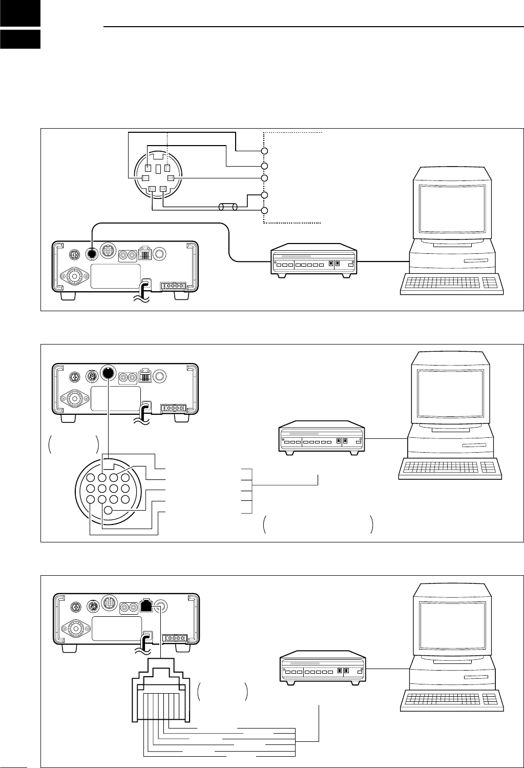
10
67
DATA COMMUNICATION
DWhen connecting to [DATA] socket
DWhen connecting to [ACC] socket
[ACC]
Rear panel
4
8
12
123
765
9
1011
13
Rear panel
view
Colors refer to connection
to the supplied ACC cable.
*1Connect SQL line when required.
MSEND (orenge)
GND (red)
SQL*1 (light green)
AF in (pink)
AF out (light blue)
TU or TNC
Personal computer
DWhen connecting to [MIC] connector
[MIC]
Rear panel
➇ SQL
➂ AF out ➃ PTT
➄ GND ➅ MIC
➆ GND
Rear panel
view TU or TNC
Personal computer
■Connections for packet
Rear panel
Personal computer
DATA
TNC SIDE
TU or TNC
RS-232C
PTT
PTTP
DATA IN
SQL
RX AUDIO
GND
TX AUDIO
qw
e
yt
r
AF OUT
DATA OUT
GND
SQ
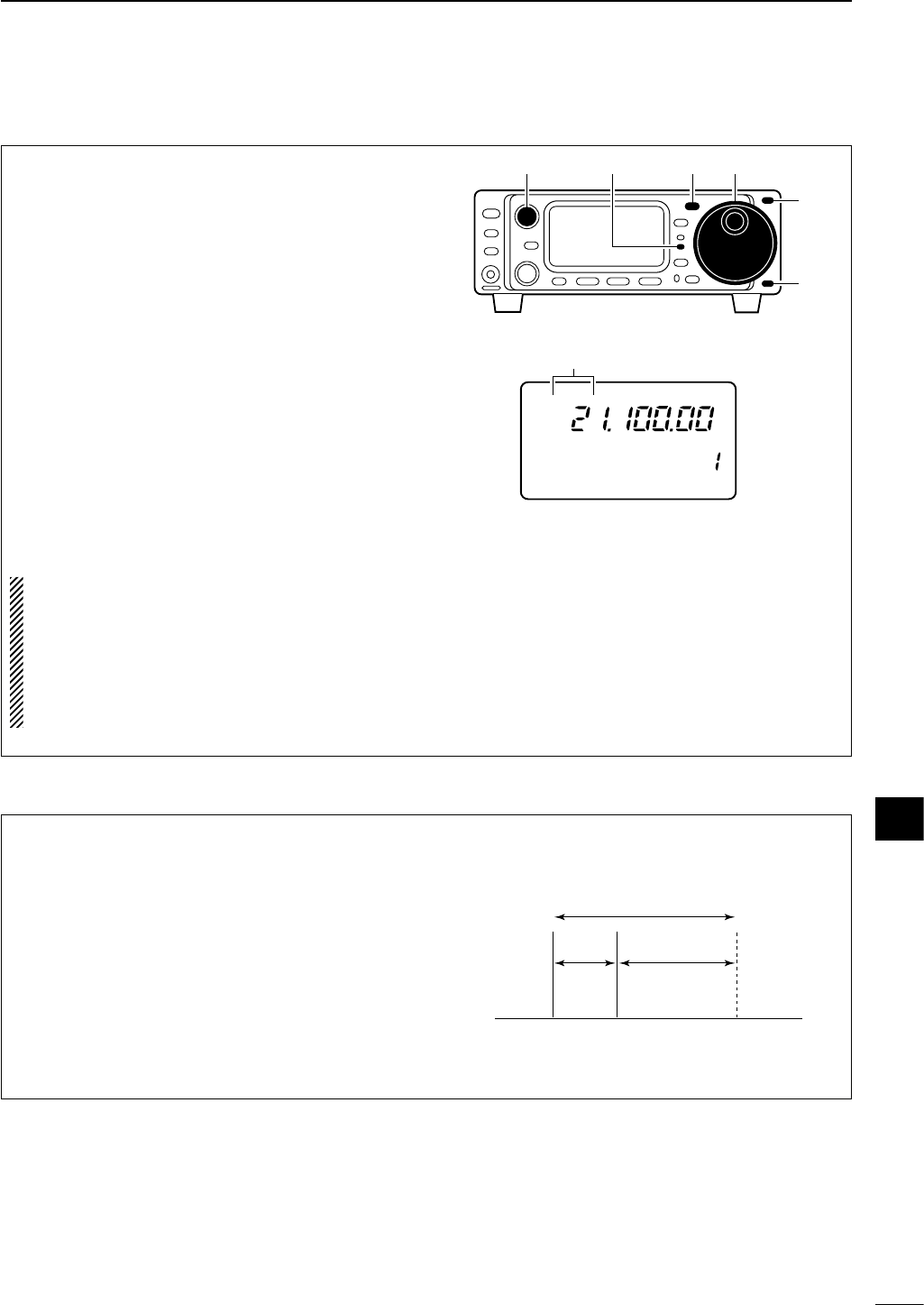
68
10
DATA COMMUNICATION
Before operating packet (AFSK) be sure to consult
the operating manual that came with your TNC.
qConnect a TNC and PC as left page.
wPush [(Y)BAND]/[(Z)BAND] to select the desired
band.
ePush [MODE] momentarily to select SSB (LSB)
mode (or select SSB-D mode).
•After USB mode is selected, push [MODE] for 1 sec.
to toggle between USB and LSB modes.
•After RTTY mode is selected, push [MODE] for 1 sec.
to toggle between RTTY and SSB-D modes.
•Generally, LSB is used on the HF bands and FM is
used for the 50 MHz band.
rRotate [AF] to set audio to a comfortable listening
level.
tRotate the main dial to tune a desired signal.
• S-meter indicates received signal strength.
yTransmit your AFSK signals using your computer’s
keyboard.
• The TX indicator lights red.
NOTE: When connecting a TNC to the ACC socket
on the rear panel, select SSB-D mode or discon-
nect the microphone and adjust ‘MIC GAIN’ to 0 in
quick set mode.
When SSB-D mode is selected, the audio input
from the [MIC] connector is automatically cut, and
the audio input from the [ACC] is used.
R
LSB
CH
VFO A
P
O
S1
5
5379
20 40
10
60dB
USB CW R
TT
Y
AM WFM
M4 1/4 TON AGC
[TX] indicator [MODE] Main dial[AF]
[Y]
[Z]
“USB” or “LSB” blinks when
SSB-D mode is selected.
■Packet (AFSK) operation
When operating AFSK in SSB mode, the indicated
frequency is the signals carrier point.
• Example— SSB-D mode
Mark freq.: 2125 Hz
Shift freq.: 200 Hz
2325 Hz
200 Hz 2125 Hz
Carrier point
(Displayed frequency)
DFrequency indication during AFSK operation
10
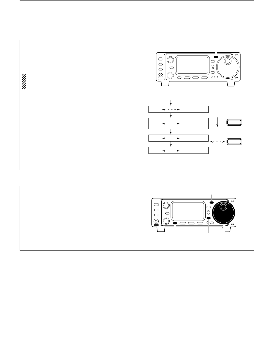
69
10 DATA COMMUNICATION
qPush [MODE] one or more times to select RTTY
mode.
wPush [MODE] for 1 sec. to SSB-D mode.
•After RTTY mode is selected, push [MODE] for 1 sec.
to toggle between RTTY and SSB-D modes.
NOTE: When SSB-D mode is selected, the audio
input from the [MIC] connector is automatically cut,
and the audio input from the [ACC] is used.
OPERATING MODE SELECTION
MODE
Push
momentarily
Memory keyer
set mode
MODE
Push
for 1 sec.
USB LSB
FM AM
SSB-D
CW
RTTY
[MODE]
qSelect SSB-D mode with [MODE].
wPush [DISPLAY] for 1 sec. to enter quick set mode.
ePush [MENU] one or more times to select “Q2
CAR SIDE,” then rotate the main dial to select
“U” (USB mode) or “L” (LSB mode).
[MODE]
Main dial[DISPLAY][MENU]
DSSB-D mode selection
DCarrier point setting QUICK SET MODE
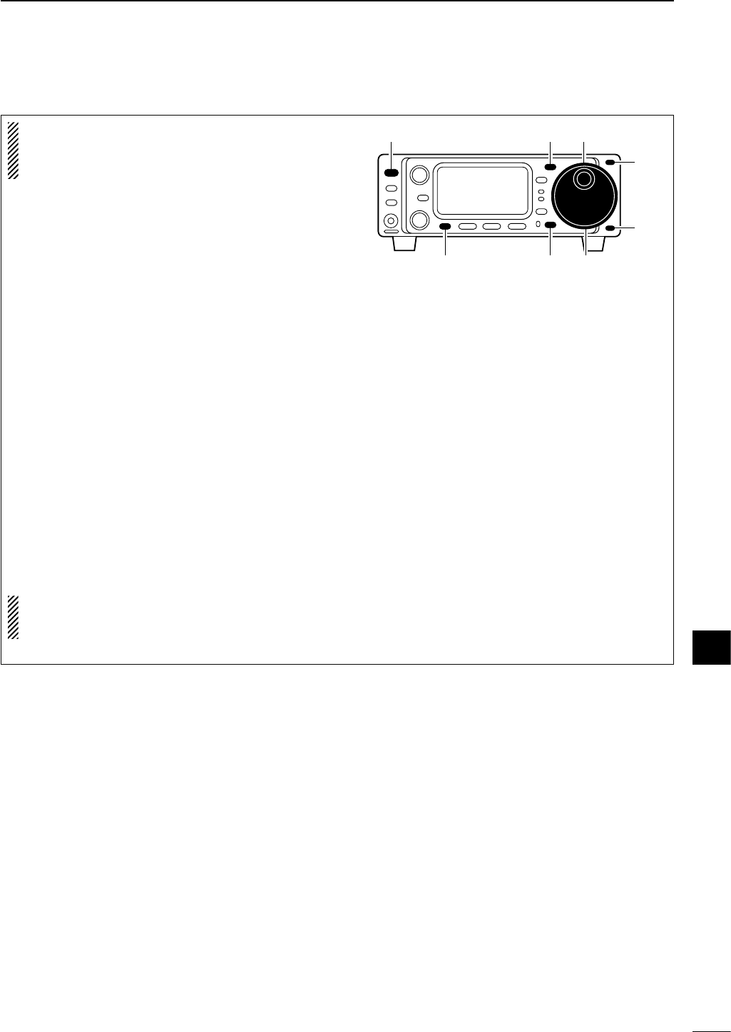
70
10
DATA COMMUNICATION
DAdjusting the transmit signal from the TNC
NOTE: For packet operation the transceiver can be
set to one of two data speeds: 1200 bps or 9600
bps. Data speed is set in initial set mode (item “36
9600 MODE”; see p.81).
qPush [POWER] for 1 sec. to turn power OFF.
wWhile pushing [LOCK], push [POWER] to turn
power ON.
• Initial set mode is selected and one of its items ap-
pears.
ePush [MENU] one or more times to select the item
“36 9600 MODE.”
• [M-CH] or [Y]/[Z] can also be used.
rRotate the main dial to select the data speeds:
1200 bps or 9600 bps.
tTo exit initial set mode, push [POWER] for 1 sec.
to turn power OFF.
yPush [POWER] to turn power ON again.
•The conditions selected in initial set mode are now ef-
fective.
When setting data transmission speed to 9600 bps,
the
DATA
signal coming from the TNC is applied ex-
clusively to the internal limiter circuitry to automati-
cally maintain bandwidth.
NEVER apply data levels from the TNC of over 0.6
Vp-p, otherwise the transceiver will not be able to
maintain the band width and may possibly interfere
with other stations.
NOTE: Read the instructions supplied with your
TNC carefully before attempting packet operation
with the IC-703.
1.When using a level meter or synchroscope, adjust
the TX audio level (
DATA IN
level) from the TNC as
follows.
0.4 Vp-p (0.2 Vrms): recommended level
0.2 Vp-p–0.5 Vp-p (0.1 Vrms–0.25 Vrms):
acceptable level
2.When not using a measuring device.
qConnect the IC-703 to a TNC.
wEnter a test mode (“CAL”, etc.) on the TNC, then
transmit some test data.
eWhen the transceiver fails to transmit test data or
transmits sporadically (TX indicator doesn’t appear
or flashes):
Decrease the TNC output level until the transmit
indicator lights continuously.
When transmission is not successful even though
the TX indicator lights continuously:
Increase the TNC output level.
Main dial[LOCK][MENU]
[MODE] Main dial[POWER]
[Y]
[Z]
10
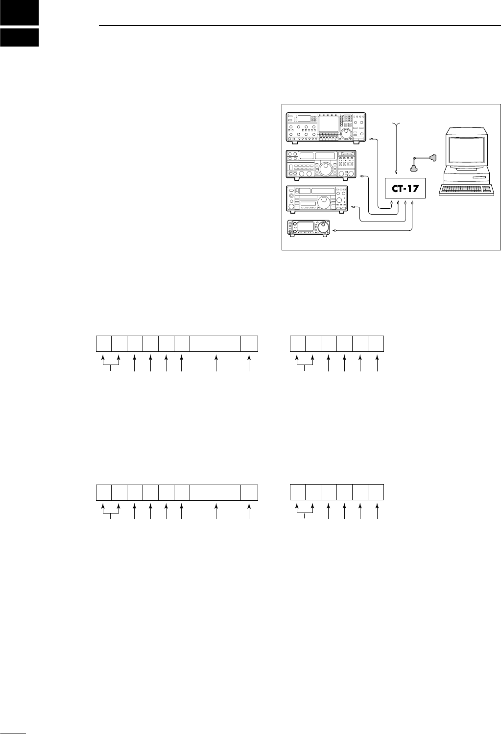
11
71
CONTROL COMMAND
CONTROLLER TO IC-703
FE FE 68 E0 Cn Sc Data area FD
Preamble code (fixed)
Transceiver’s default address
Controller’s default address
Command number
(see table at right)
Sub command number
(see table at right)
BCD code data for frequency or
memory number entry
End of message code (fixed)
OK MESSAGE TO CONTROLLER
FE FE 68 E0 FB FD
Preamble code (fixed)
Transceiver’s default address
Controller’s default address
OK code (fixed)
End of message code (fixed)
NG MESSAGE TO CONTROLLER
FE FE 68 E0 FA FD
Preamble code (fixed)
Transceiver’s default address
Controller’s default address
NG code (fixed)
End of message code (fixed)
IC-703 TO CONTROLLER
FE FE E0 68 Cn Sc Data area FD
Preamble code (fixed)
Controller’s default address
Transceiver’s default address
Command number
(see table at right)
Sub command number
(see table at right)
BCD code data for frequency or
memory number entry
End of message code (fixed)
DCI-V connection example
The transceiver can be connected through an optional
CT-17
CI
-
V LEVEL CONVERTER
to a personal computer
equipped with an RS-232C port. The Icom Communi-
cation interface-V (CI-V) controls the following func-
tions of the transceiver.
Up to four Icom CI-V transceivers or receivers can be
connected to a personal computer equipped with an
RS-232C port. See p. 82 for setting the CI-V condition
using initial set mode.
DData format
The CI-V system can be operated using the following
data formats. Data formats differ according to com-
mand numbers. A data area is added for some com-
mands.
Personal
computer
IC-703
9–15 V DC
■Remote jack (CI-V) information
72
11
CONTROL COMMAND
D
Command table
Command Sub command Description
00 — Send frequency data
01 Same as Send mode data
command 06
02 — Read band edge frequencies
03 — Read operating frequency
04 — Read operating mode
05 — Set operating frequency
06 00 Select LSB
01 Select USB
02 Select AM
03 Select CW
04 Select RTTY
05 Select FM
07 Select CW-R
08 Select RTTY-R
07 — Select VFO mode
00 Select VFO A
01 Select VFO B
A0 Equalize VFO A and VFO B
B0 Exchange VFO A and VFO B
08 — Select memory mode
0001–0105* Select memory channel
*1A=0100, 3b=0105
09 — Memory write
0A — Memory to VFO
0B — Memory clear
0E 00 Scan stop
01 Programmed/memory scan start
0F 00 Turn the split function OFF
01 Turn the split function ON
10 00 Select 10 Hz (1 Hz) tuning step
01 Select 100 Hz tuning step
02 Select 1 kHz tuning step
03 Select 5 kHz tuning step
04 Select 9 kHz tuning step
05 Select 10 kHz tuning step
06 Select 12.5 kHz tuning step
07 Select 20 kHz tuning step
08 Select 25 kHz tuning step
09 Select 100 kHz tuning step
11 — Select/read attenuator (00=OFF,
20=ON (20 dB))
13 00 Announce with voice synthesizer
01 (00=all data; 01=frequency and
02 S-meter level; 02=operating mode)
14 01 + Level data [AF] level setting (0=max. CCW to
255=max. CW)
02 + Level data [RF] level setting (0=max. CCW to
255=11 o’clock)
03 + Level data [SQL] level setting (0=11 o’clock to
255=max. CW)
04 + Level data [IF SHIFT] position setting (0=max.
CCW; 128=center; 255=max. CW)
06 + Level data Noise reduction level setting
(0=min. to 255=max.)
07 + Level data Twin PBT (inside) setting (0=max.
CCW, 128=center, 255=max. CW)
08 + Level data Twin PBT (outside ) setting
(0=max. CCW, 128=center,
255=max. CW)
09 + Level data CW pitch setting (0=300 Hz,
128=600 Hz, 255=900 Hz)
Command Sub command Description
14 0A + Level data RF power setting (0=mini. to
255=max.)
0B + Level data Microphone gain setting (0=mini.
to 255=max.)
0C + Level data Key speed setting (0=slow to
255=fast)
0E + Level data
COMP Level setting (0=0 to 10=10)
0F + Level data Break-IN DELAY setting (20=2.0d
to 130=13.0d)
15 01 Read squelch condition
02 Read S-meter level
11 Read RF power meter
12 Read SWR meter
13 Read ALC meter
16 02 Preamp (0=OFF; 1=preamp 1;
2=preamp 2)
12 AGC selection (1=Fast; 2=Slow)
22 Noise blanker (0=OFF; 1=ON)
40 Noise reduction (0=OFF; 1=ON)
41 Auto notch (0=OFF; 1=ON)
42 Subaudible tone (0=OFF; 1=ON)
43 Tone squelch (0=OFF; 1=ON)
44
Speech compressor (0=OFF; 1=ON)
45 Monitor (0=OFF; 1=ON)
46 VOX function (0=OFF; 1=ON)
47 Break-in (0=OFF; 1=semi break-
in; 2=full break-in)
19 00 Read the transceiver ID
1A 00 Send/read memory contents
01 Send/read band stacking register
contents (see p. 73 for details)
02 Send/read memory keyer con-
tents (see p. 73 for details)
0301 Send/read beep emission set
(0=OFF, 1=ON)
0302 Send/read band edge beep set
(0=OFF, 1=ON)
0303 Send/read beep output level set
(0=min. to 255=max.)
0304 Send/read beep limit set (0=OFF,
1=ON)
0305 Send/read CW carrier point set
(0=LSB, 1=USB)
0306 Send/read CW side tone level set
(0=min. to 255=max.)
0307 Send/read CW side tone limit set
(0=OFF, 1=ON)
0308 Send/read 9600 bps mode set
(0=OFF, 1=ON)
0309 Send/read VOX gain set (0=min.
to 255=max.)
0310 Send/read anti VOX gain set
(0=min. to 255=max.)
0311 Send/read VOX delay time set
(0=0 sec. to 20=2.0 sec.)
0312 Send/read meter selection
(0=Power, 1=SWR, 3=ALC)
0313 Send/read SSB carrier frequency
(00=–200 Hz to 40=200 Hz;
10 Hz steps)
CW: Clockwise, CCW: Counter Clockwise
11
73
11 CONTROL COMMAND
Command table (continued)
DBand stacking register
To send or read the desired band stacking register’s con-
tents, combined code of the frequency band and register
codes as follows are used.
For example, when sending/reading the contents in the
21 MHz band, the code “0701” is used.
• Frequency band code
• Register code
DCodes for memory keyer contents
To send or read the desired memory keyer contents, the
channel and character codes as follows are used.
• Channel code
• Character’s code
DCodes for memory name contents
To send or read the desired memory name settings, the
character codes, instructed codes for memory keyer con-
tents as above, and follows are additionally used.
•Character’s code— Alphabetical characters
•Character’s code— Symbols
Command Sub command Description
1A 0314 Send/read RTTY marker fre-
quency (0=1275 Hz, 1=1615 Hz,
2=2125 Hz)
0315 Send/read RTTY shift width
(0=170 Hz, 1=200 Hz, 2=425 Hz)
0316 Send/read RTTY keying polarity
(0=Normal, 1=Reverse)
0317 Send/read noise blanker level
(0=min. to 255=max.)
0318 Send/read key type (0=Normal,
1=Reverse, 2=Bug, 3=OFF,
4=Mic. [UP]/[DN])
0319 Send/read CW keyer dot/dash
ratio (28=1:1:2.8 to 45=1:1:4.5)
0320 Send/read CW keyer repeat time
(01=1 sec. to 60=60 sec.)
0321 Send/read CW keyer transmission
indication (0=Normal, 1=First 3-
character, 2= First 3-character+
contact number)
0322 Send/read contact number style
(0=Normal, 1=190→ANO,
2=190→ANT, 3=90→NO,
4=90→NT)
0323 Send/read count up trigger chan-
nel (1=MK1, 2=MK2, 3=MK3)
0324
Send/read present number (1–999)
04 Send/read DATA mode (0=OFF,
1=ON)
1B 00 Set/read repeater tone frequency
01 Set/read TSQL tone frequency
1C 00 Set/read the transceiver’s condi-
tion (0=Rx; 1=Tx)
01 Set/read antenna tuner condition
(0=OFF, 1=ON, 2=Start tuning or
while tuning)
Character ASCII code Character ASCII code
a–z 61–7A — —
Code Freq. band Frequency range (unit: MHz)
01 1.8 1.800000–1.999999
02 3.5 3.400000–4.099999
03 7 6.900000–7.499999
04 10 9.900000–10.499999
05 14 13.900000–14.499999
06 18 17.900000–18.499999
07 21 20.900000–21.499999
08 24 24.400000–25.099999
09 28 28.000000–29.999999
10 50 50.000000–54.000000
11 GENE Other than above
Character ASCII code
Description
0–9 30–39 Numerals
A–Z 41–5A Alphabetical characters
space 20 Word space
/ 2F Symbol
? 3F Symbol
, 2C Symbol
. 2E Symbol
^ 5E e.g., to send
BT
, enter ^4254
✱2A Inserts contact number (can be
used for 1 channel only)
Code Channel number
01 MK1
02 MK2
03 MK3
Character ASCII code Character ASCII code
!21#23
$24%25
&26¥5C
?3F ” 22
’27`60
+2B–2D
:3A;3B
=3D<3C
>3E ( 28
)29[5B
]5D{7B
}7D|7C
_5F–7E
Code Registered number
01 1
12
74
SET MODE
■General
Set mode is used for programming infrequently
changed values or conditions of functions. The IC-703
has 2 separate set modes: quick set mode and initial
set mode.
qWhile power is ON, push [DISPLAY] for 1 sec.
•Quick set mode is selected and one of its items ap-
pears.
•Quick set mode items vary depending on the selected
operating mode (SSB, FM, etc.).
wPush [MENU] one or more times to select the de-
sired item.
• [M-CH] or [Y]/[Z] can also be used.
eRotate the main dial to set the values or conditions
for the selected item.
rRepeat steps wand eto set other items.
tTo exit quick set mode, push [DISPLAY] momen-
tarily.
[MENU] [DISPLAY][M-CH]
[POWER] Main dial
[Y]
[Z]
Q1 RF POWER
USB
Item number
Item
Value or
condition
[DISPLAY EXAMPLE: QUICK SET MODE]
P
O
S1
5
53792040
10
60dB
DQuick set mode operation
qPush [POWER] for 1 sec. to turn power OFF.
wWhile pushing [LOCK], push [POWER] to turn
power ON.
• Initial set mode is selected and one of its items ap-
pears.
ePush [MENU] one or more times to select the de-
sired item.
• [M-CH] or [Y]/[Z] can also be used.
rRotate the main dial to set the values or conditions
for the selected item.
tRepeat steps eand rto set other items.
yTo exit initial set mode, push [POWER] for 1 sec.
to turn power OFF.
uPush [POWER] to turn power ON again.
•The conditions selected in initial set mode are now ef-
fective.
[MENU] [LOCK][M-CH]
[POWER] Main dial
[Y]
[Z]
Item number
Item
Value or
condition
1 MAX POWSET
[DISPLAY EXAMPLE: INITIAL SET MODE]
DInitial set mode operation
11
12
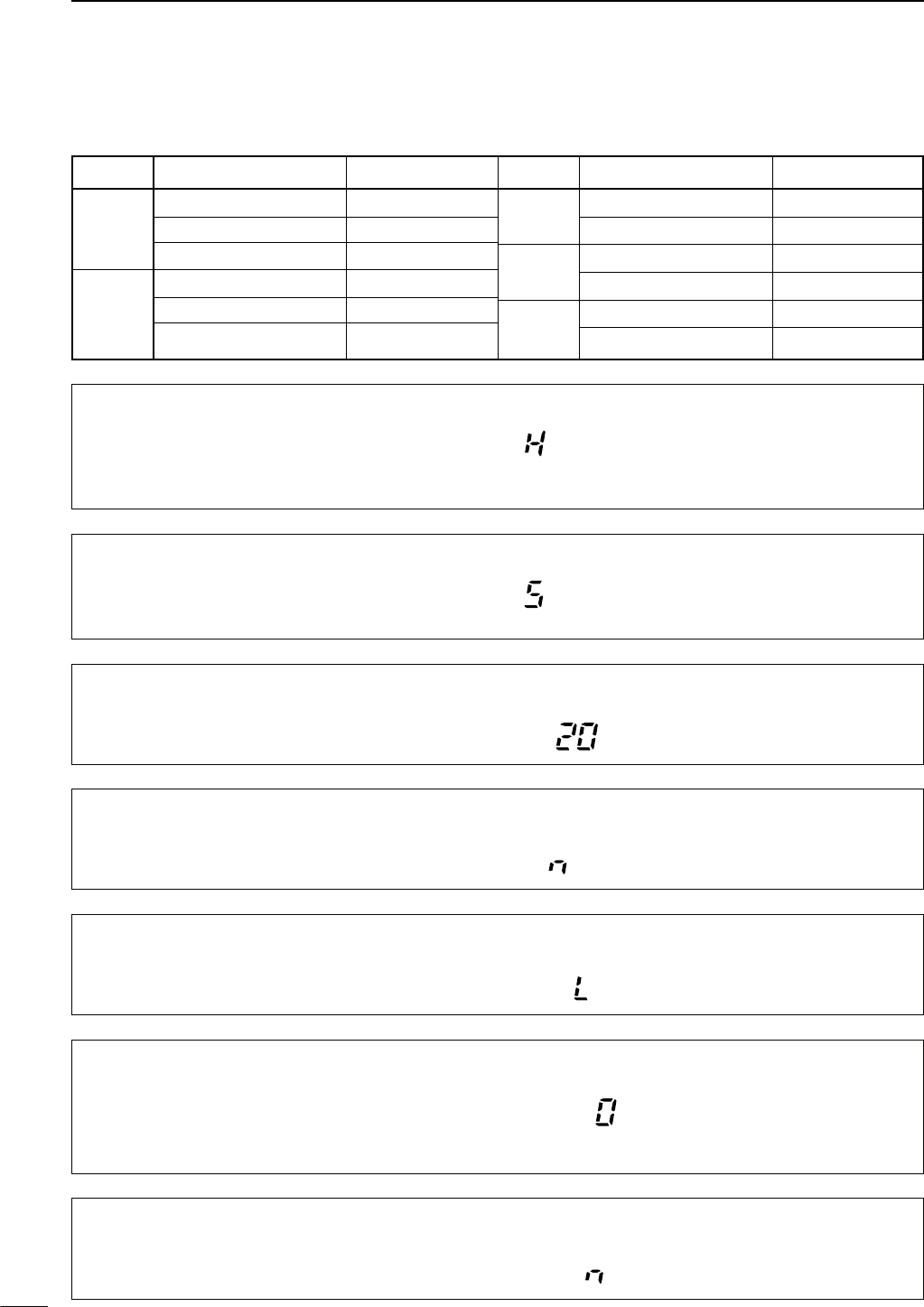
■Quick set mode items
Q1 RF POWER (all modes)
This item adjusts the RF output power. The RF out-
put power can be adjusted from L, 1 to 9 and H for in-
dication, however, it can be adjusted continuously.
The default is H (maximum power).
Note that while adjusting the output
power, the power meter is displayed
automatically.
Q2 MIC GAIN (SSB/AM/FM modes)
This item adjusts microphone gain from 1 to 10 for in-
dication, however, it can be adjusted continuously.
The default is 5.
Note that while adjusting mic gain, the
ALC meter is displayed automatically.
Q2 KEY SPEED (CW mode)
This item adjusts the CW key speed. The key speed
can be selected from 6 to 60 wpm.
The default is 20 wpm.
CW
Q2 RTTY REV (RTTY mode)
This item selects RTTY or åRTTY (RTTY reverse)
mode.
The default is normal.
R
TT
Y
Q3 CW REV (CW mode)
This item selects CW or CWå(CW reverse) mode.
The default is normal.
CW
Q3 CARRIER Frq (SSB mode)
This item adjusts the carrier frequency (BFO fre-
quency), allowing you to change the audio character-
istics. Selectable values are –200 to +200 Hz in 10 Hz
steps.
USB
The default is 0 Hz.
Q2 CAR SIDE (SSB-D mode)
This item selects the carrier point. USB mode or LSB
mode are selectable.
The default is LSB mode.
LSB
75
12 SET MODE
Mode Set mode item Default setting
Q1 RF POWER H
SSB Q2 MIC GAIN 5 level
Q3 CARRIER Frq 0 [Hz]
Q1 RF POWER H
CW Q2 KEY SPEED 20 [WPM]
Q3 CW REV n (normal)
Mode Set mode item Default setting
RTTY Q1 RF POWER H
Q2 RTTY REV n (normal)
SSB-D Q1 RF POWER H
Q2 CAR SIDE L (LSB side)
FM/AM Q1 RF POWER H
Q2 MIC GAIN 5 level
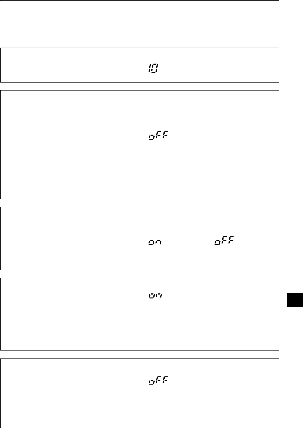
When “3 SIMPLE MODE” is set to ON, * marked items are undisplayed. 76
12
SET MODE
4 MODE SELECT (Mode Availavility)
This item is available in all modes, and allows you to
simplify operation by inhibiting the selection of un-
needed operating modes during normal operation.
For example if you are operating mobile and only plan
on using FM and AM modes, use “4 MODE SE-
LECT” to inhibit access to all other modes (SSB, CW,
RTTY), thereby making selection of AM or FM quick
and easy.
The default is on for all operating
modes. To toggle an operating mode
on or off, push (or push and hold)
[MODE] one or more times until the
desired mode is displayed, then rotate
the main dial to set on or off.
*5 MODE POWSET
This item allows you to set the output power for each
operating mode.
on : Output power can be set for each mode groups.
oFF: Same output power for every mode.
The mode groups are separated ‘SSB-D/USB/LSB,’
‘CW’ and ‘RTTY/AM/FM.’
The default is OFF.
■Initial set mode items
2 PoSAVE MODE
The power save mode reduces the current drain to
conserve battery power. This function is convenience
for battery operation.
AUTO : The power save function starts in 1:1 (200
msec.:200 msec.) ratio when no signal is re-
ceived for 5 sec., then the ratio becomes in
1:4 (200 msec.:800 msec.) and 1:8 (200
msec.:1600 msec.) after no signal is received
every 60 sec. are past.
(1 :) 1, 4, 8, 16:
The power save function activates selected
ratio.
oFF : The power save function does not activate.
The default is OFF.
3 SIMPLE MODE
This item select the simple mode and normal mode.
on : Simple mode is selected. (*) marked items in initial
set mode are hidden, and push [DISPLAY] to se-
lect Main menu or Sub menu only, Graphic menu
also hidden.
oFF : Normal mode is selected.
Simple mode ON Simple mode OFF
(default)
1 MAX POWSET
This item selects maximum output power. The max.
power is can be set 10, 5, 2.5, 1 or 0.5 W.
The default is 10 W.
(Output power setting for modes)
(Max. output power setting)
(Power save setting)
(Simple mode setting)
12
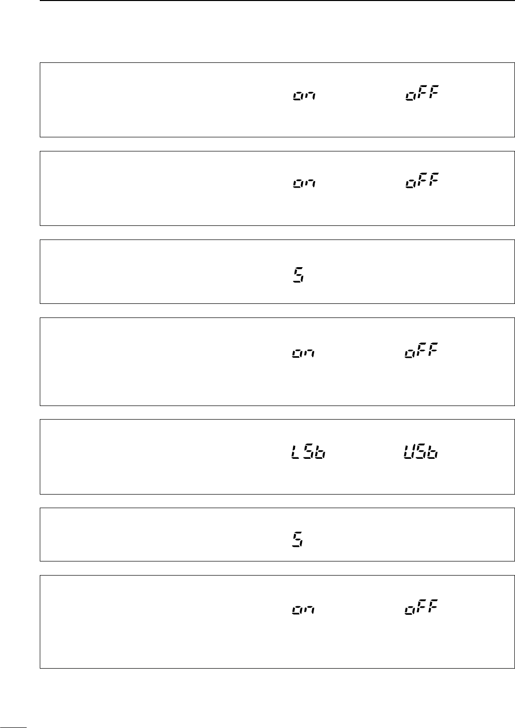
77
12 SET MODE
*10 CW NOR SIDE
This item select the carrier point of CW mode from
LSB and USB.
The carrier point is
LSB side (default).
The carrier point is
USB side.
6 BEEP (Confirmation beeps)
A beep sounds each time a switch is pushed to con-
firm it. This function can be turned OFF for silent op-
eration.
Confirmation beep ON
(default)
Confirmation beep OFF
*7 BAND BEEP (Band edges beep)
A beep sounds when an operating frequency enters or
exits a transmit frequency range. This functions inde-
pendent of the confirmation beep setting (above).
Band beep ON
(default)
Band beep OFF
8 BEEP LEVEL
When “6 BEEP” is set ON, this item adjust the con-
firmation beep level. Adjustable levels are 0 to 10 in 1
steps.
The default is 5.
*9 BEEP LIMIT
This item allows you to set a maximum volume level
for confirmation beep tones. Confirmation beep tones
are linked to the [AF] control until a specified volume
level is reached— further rotation of the [AF] control
will not increase the volume of the beep tones.
Beep limit ON
(default)
Beep limit OFF
*12 SID-T LIMIT
This item sets the CW side tone level limit. When the
[AF] control is rotated above a specified level, the CW
side tone does not increase.
on : CW side tone level is limited. (default)
oFF : CW side tone level is not limited.
CW side tone limit ON
(default)
CW side tone limit OFF
11 SID-T LEVEL
This item sets the CW side tone output level. Selec-
table levels are 0 to10 in 1 steps.
The default is 5.
(Beep audio level limit)
(CW carrier point setting)
(CW side tone level)
(CW side tone level limit)
When “3 SIMPLE MODE” is set to ON, * marked items are undisplayed.
(Beep level adjustment)
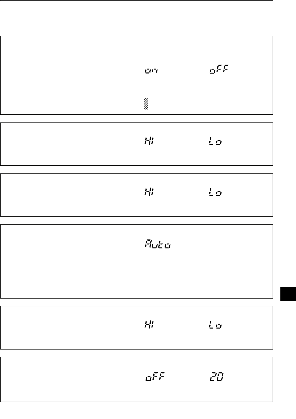
78
12
SET MODE
*18 AUTO OFF
The auto power OFF function can be used to auto-
matically turn the transceiver OFF after a specified
time of operation. This item can be set to 30 min., 60
min., 90 min., 120 min., or OFF.
Auto power OFF set to
20 min.
Auto power OFF
deactivates. (default)
*13 SYNC TUNING
This item selects the displayed frequency shift func-
tion from ON and OFF.
When this function is activated, the receiving signal
can be kept in receive even when the operating mode
is changed between SSB and CW.
oN : The displayed frequency shifts when the oper-
ating mode is changed between SSB and CW.
oFF: The displayed frequency does not shift. (default)
The frequency shifting value may differ according
to the CW pitch setting.
Synchronous tuning ON Synchronous tuning OFF
(default)
15 KEY LIGHT
The key/switch backlighting can be set to high, low or
OFF to suit ambient lighting.
Key/switch backlighting
set to high (default).
Key/switch backlighting
set to low.
17 LED BRIGHT (LED brightness)
The LED brightness control for front panel can be set
to high or low.
LED brightness set
to high.
LED brightness set
to low (default).
*16 LIGHT TIMER
The Light timer can be set to AUTO, ON or OFF to
suit lighting condition.
Auto: Automatically select “on” or “oFF” depends on
power supply voltage. (default)
on : Lights when some operation is performed, goes
out after 5 sec.
oFF : Lights continuously during transceiver power is
ON.
Default is Auto.
14 BACK LIGHT
The function display backlighting can be set to high,
low or OFF to suit ambient lighting.
Display backlighting set to
high (default).
Display backlighting set to
low.
(SSB/CW frequency shift setting)
(Display backlighting)
(Key/switch backlighting)
(Light timer setting)
(Automatic power OFF)
12
When “3 SIMPLE MODE” is set to ON, * marked items are undisplayed.
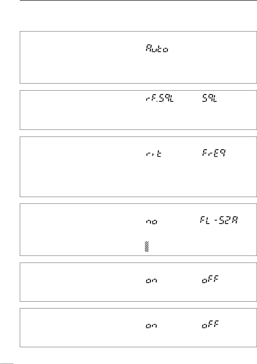
79
12 SET MODE
*23 PEAK HOLD
When the peak hold function is ON, the highest acti-
vated segment of the meter remains visible for 0.5
sec.; when OFF, the meter functions normally.
Peak hold ON
(default)
Peak hold OFF
*20 RF/SQL (RF gain/squelch control)
The [RF/SQL] control can be set as the squelch con-
trol (default), the RF/squelch control (USA version de-
fault) or automatic (acts as squelch in FM/AM modes;
as RF in SSB/CW/RTTY modes). (See p. 24)
The [RF/SQL] control
functions as squelch
control only.
The [RF/SQL] control
functions as RF gain
and squlch control for
all modes.
*21 SUB DIAL (Sub dial setting)
When this item is set to “rit,” pushing [RIT/SUB] turns
the RIT function ON (lights red)—rotating [M-CH]
changes the RIT frequency; when this item is set to
“FrEq,” pushing [RIT/SUB] turns the sub dial function
ON (lights green)—rotating [M-CH] changes the op-
erating frequency. Note that in FM and AM modes,
pushing [RIT/SUB] always selects the sub dial func-
tion (lights green), regardless of this setting.
Pushing [RIT/SUB]
selects the RIT function
(default).
Pushing [RIT/SUB]
selects the sub dial function.
22 OPT. FIL
When an optional filter is installed, this selection is
necessary, otherwise the filters cannot be selected.
Selections available are FL-52A, FL-53A, FL-222, FL-
257 and none (default). See p. 49 for usable filters for
each mode and see p. 87 for filter installation. Although the FL-96 is not listed on the option list, IC-703
would take FL-96 as well as other optional filter.
No filters are selected
(default).
FL-52A (for CW narrow filter)
is selected.
19 CURRENT IP
This item set the control of current intercept point for
power saving.
Auto: Automatically select “on” or “oFF” depends on
power supply voltage. (default)
on : Power saving mode continuously.
oFF : Priority to intercept point.
Default is Auto.
*24 QUICK SPLIT
When this item is set to ON, pushing [(F-1)SPL] for 1
sec. in the M1 display sets the undisplayed VFO fre-
quency to the displayed VFO frequency plus the split
offset, and activates split operation.
Quick split function ON
(default).
Quick split function OFF.
(Quick split function)
(Optional filter selection)
(Peak meter hold setting)
When “3 SIMPLE MODE” is set to ON, * marked items are undisplayed.
(Current intercept point)
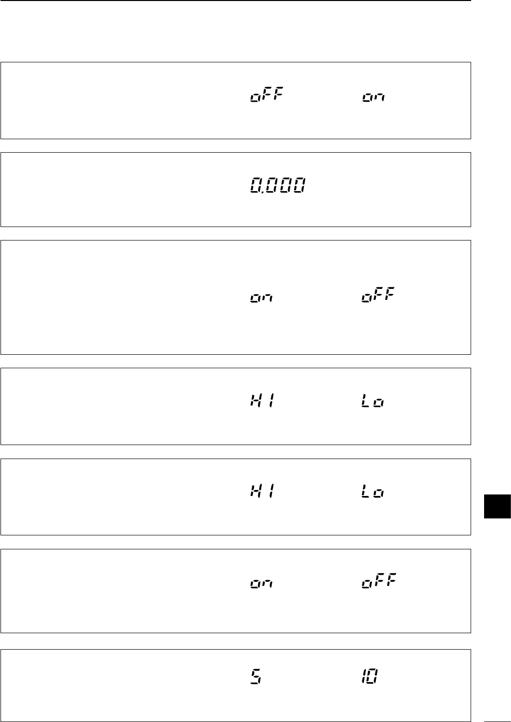
80
12
SET MODE
26 SPL OFFSET
This item sets the offset (difference between transmit
and receive frequencies) for the quick split function.
Available offset frequencies are –9.999 to 9.999 MHz
in 0.001 MHz (1kHz) steps.
Default is 0.000 MHz.
*25 SPLIT LOCK
When this item is ON, the main dial can be used to
adjust the transmit frequency while pushing
[(F-3)XFC] even when the lock function is activated.
Split lock function OFF
(default)
Split lock function ON
*30 AM NB (Noise blanker in AM mode)
When this item is set to ON, the noise blanker func-
tion is available in AM mode. This is useful when
communicating in AM mode (the noise blanker func-
tion should not be used when listening to regular AM
broadcasts as it may degrade the received audio).
Noise blanker is available
on AM mode. (default)
Noise blanker is not
available on AM mode.
28 SCAN SPEED (Scanning speed)
This item sets the rate at which channels or frequen-
cies are scanned during scan operations. High or low
can be selected.
Scan speed is set to high
(default).
Scan speed is set to low.
29 U/D SPEED ([UP]/[DN] speed)
This item sets the rate at which frequencies are
scanned through when the [UP]/[DN] switches of the
microphone are pushed and held. High or low can be
selected.
Up/down speed is set to
high (default).
Up/down speed
is set to low.
27 SCAN RESUME
This item sets the scan resume function ON or OFF.
on : Scan resumes 10 sec. after stopping on a sig-
nal (or 2 sec. after a signal disappears);
oFF: Scan does not resume after stopping on a sig-
nal. For the priority watch, setting to OFF
pauses the watch until signal disappears and
scan resumes.
Scan resume function is
turned ON (default).
Scan resume function is
turned OFF.
31 PAD CH (Available memo pads)
This item sets the number of memo pad channels
available. 5 or 10 memo pads can be selected.
5 memo pads are available
(default).
10 memo pads are
available.
(Split lock function)
(Split offset frequency)
(Scan resume condition)
12
When “3 SIMPLE MODE” is set to ON, * marked items are undisplayed.
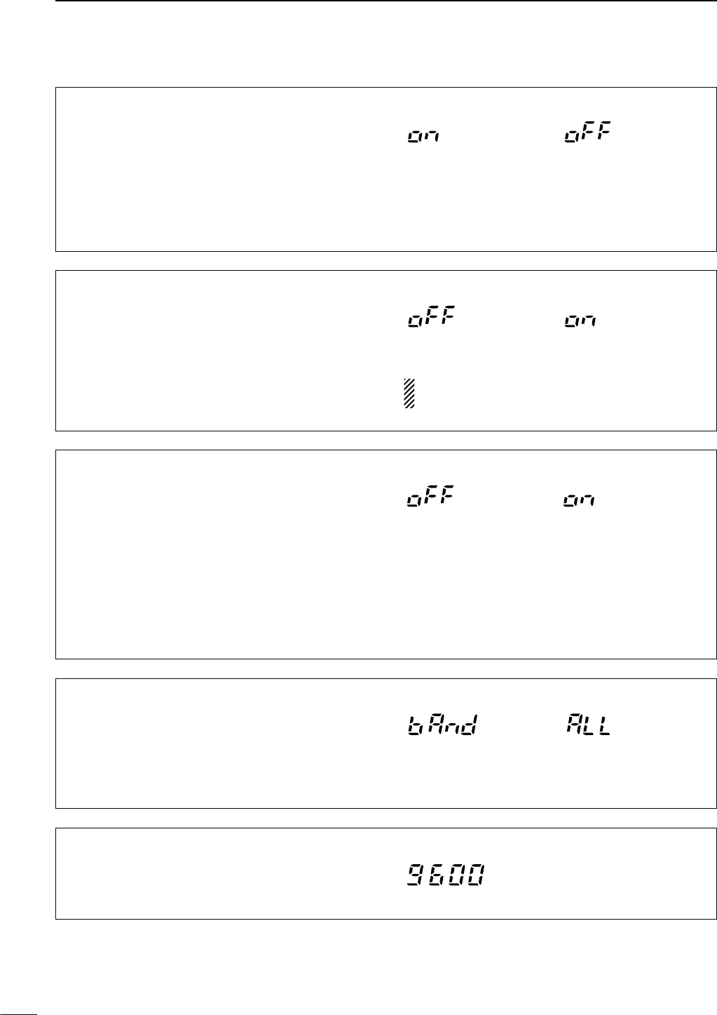
81
12 SET MODE
32 PWR ON CHK
This item selects the indication ON or OFF when turn-
ing power ON.
on : The Transceiver briefly displays ‘All indication,’
‘RF power’ and ‘Power supply voltage’ when
turning power ON.
oFF: The display goes directly to frequency indication
at power ON.
Power on check ON
(default)
Power on check OFF
*35 TUNER SW
This item select BAND or ALL.
bAnd : [TUNER] switch ON/OFF condition is re-
mained for each band.
ALL : [TUNER] switch ON/OFF condition is com-
monly remained for all band.
The default is BAND.
*34 PTT TUNE
(PTT tune function)
This item set the PTT tuner start function ON or OFF.
This function activates internal tuner and optional AT-
180/AH-4
ANTENNA TUNER
, when connected.
on : The tuner is always tuned when the PTT is
pushed after the frequency is changed (more
than 1% from last-tuned frequency). (Internal
tuner or connected AT-180)
Tuning can be started automatically at the mo-
ment the PTT is pushed. (Connected AH-4)
oFF : PTT tuner start function OFF.
Tuning starts when pushing
[PTT] on a new frequency.
Tuning starts only when
[TUNER] is pushed
(default)
.
*33 A-TUNE STRT
The optional AT-180
ANTENNA TUNER
has an automatic
start capability which starts tuning if the SWR is
higher than 1.5–3.
oFF: The tuner remains OFF even when the SWR is
poor (1.5–3).
on : Automatic tune starts even when the tuner is
turned OFF.
NOTE: Even when “on” is selected, automatic tune
does not start for the 50 MHz band.
Auto tune function OFF
(default).
Auto tune function ON.
36 9600 MODE
(Packet data speed)
This item is used to change the communications
speed for packet operation. The data socket speed
can be set to 1200 or 9600 baud.
Default is 9600 baud.
(Auto tune start function)
When “3 SIMPLE MODE” is set to ON, * marked items are undisplayed.
(Power on check function)
(Tuner switch condition)
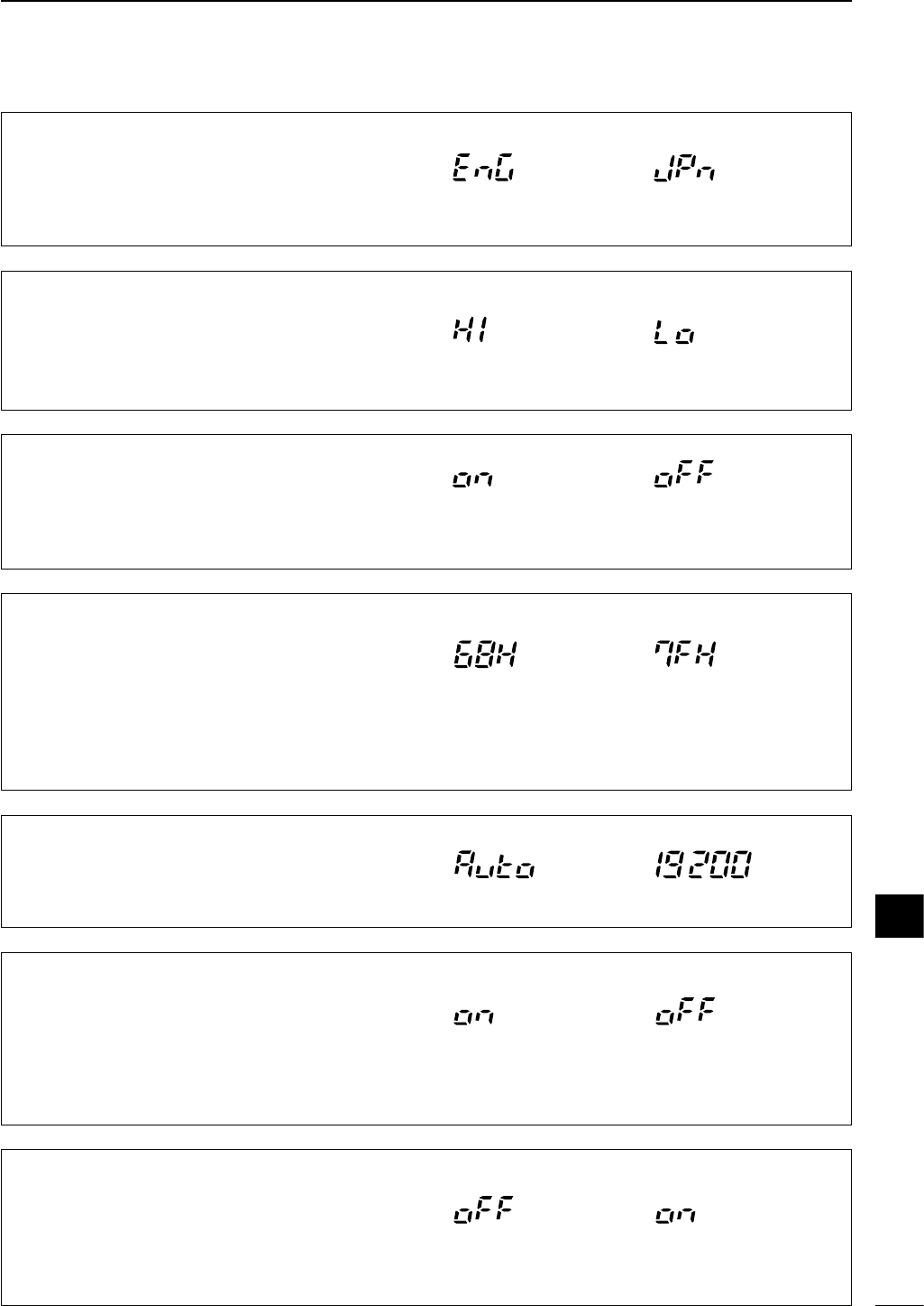
82
12
SET MODE
37 SPEECH LANG
When the optional UT-102
VOICE SYNTHESIZER UNIT
is
installed, you can select between English and Japan-
ese as the language.
Voice synthesizer functions
in English (default).
Voice synthesizer
functions in Japanese.
(Voice synthesizer language)
39 S-LVL SPCH
When an optional UT-102
SPEECH SYNTHESIZER UNIT
is installed, the synthesizer can be set to read out the
frequency/mode only, or both the frequency/mode
and S-meter level.
Voice synthesizer reads out
both the frequency/mode
and S-meter level (default).
Voice synthesizer reads
out the frequency/mode
only.
40 CI-V ADDRES
To distinguish equipment, each CI-V transceiver has
its own Icom standard address in hexadecimal code.
The IC-703’s address is 68H.
When 2 or more IC-703’s are connected to an op-
tional CT-17
CI
-
V LEVEL CONVERTER
, rotate the main
dial to select a different address for each IC-703 in
the range 01H to 7FH.
Address set to 68H
(default).
Address set to 7FH.
*41 CI-V BAUD
This item sets the data transfer rate. When “Auto” is
selected, the baud rate is automatically set according
to the connected controller or remote controller.
Auto baud rate (default) 19200 bps
*43 CI-V 731
When connecting the IC-703 to the IC-735 for trans-
ceiver operation, you must change the operating fre-
quency data length to 4 bytes.
•This item
MUST
be set to “on” only when operating trans-
ceiver with the IC-735.
Frequency data set to
5 bytes (default).
Frequency data set to
4 bytes.
*42 CI-V TRN (CI-V transceive)
Transceiver operation is possible with the IC-703 con-
nected to other Icom HF transceivers or receivers.
When “on” is selected, changing the frequency, oper-
ating mode, etc. on the IC-703 automatically changes
those of connected transceivers (or receivers) and
vice versa.
Transceive ON
(default)
Transceive OFF
38 SPEECH SPD
When the optional UT-102
VOICE SYNTHESIZER UNIT
is
installed, you can select the speech speed of synthe-
sizer output between faster or slower.
Speech speed
is faster (default).
Speech speed
is slower.
(Voice synthesizer speed)
(S-meter level speech)
(CI-V address setting)
(CI-V data transffer rate)
(CI-V operating frequency data length)
12
When “3 SIMPLE MODE” is set to ON, * marked items are undisplayed.
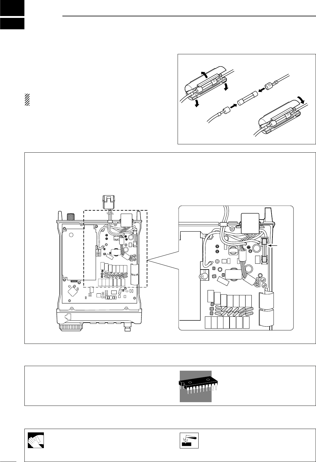
13
83
MAINTENANCE
If the transceiver becomes dusty or dirty,
wipe it clean with a dry, soft cloth.
AVOID the use of strong chemical solvents
such as thinner, benzine or alcohol to clean
the transceiver. These may damage the
transceiver’s surfaces.
■Fuse replacement
If a fuse blows or the transceiver stops functioning, try
to find the source of the problem, and replace the dam-
aged fuse with a new, rated fuse.
CAUTION: Disconnect the DC power cable from
the transceiver when changing a fuse.
The IC-703 has three of fuses (DC power cable fuses×
2, circuitry fuse×1) installed for transceiver protection.
• Fuses ............................................. F.G.B. 125 V 4 A
DC POWER CABLE FUSE REPLACEMENT
q
w
e
CIRCUITRY FUSE REPLACEMENT
The 13.8 V DC from the DC power cable is applied to
all units in the IC-703, except for the power amplifier,
through the circuitry fuse. This fuse is installed in the
PA unit.
■Memory backup
All of the CPU’s memory is backed up by an EEP-
ROM (Electronically-Erasable Programmable Read-
Only Memory). All data you set, such as VFO,
memory, set mode contents, etc. is stored in this
EEPROM. There is no internal lithium battery.
■Cleaning
Fuse
14
84
TROUBLESHOOTING
The following chart is designed to help you correct
problems which are not equipment malfunctions.
If you are unable to locate the cause of a problem or
solve it through the use of this chart, contact your near-
est Icom Dealer or Service Center.
PROBLEM
POWER SUPPLY
RECEIVE
POSSIBLE CAUSE SOLUTION REF.
Power does not come
on when the [POWER]
switch is pushed.
No sound comes from
the speaker.
Sensitivity is low.
Receive audio is distor-
ted.
Receive signal is distor-
ted with strong signals.
DC power cable is improperly
connected.
Fuse is blown.
Battery is exhausted if you are using
a 12 V battery as the power source.
Reconnect the power cable correctly.
Check for the cause, then replace the
fuse with a spare one.
(Fuses are installed in two places. One is
installed in the DC power cable and the
other is installed in the PA unit.
Check the battery voltage with the
[POWER] pushed IN.
p. 15
p. 83
—
pgs. 1,
17, 23
pgs. 1,
17, 24
—
p. 14
—
—
pgs.
64– 66
p. 46
p. 23
p. 47
p. 48
p. 46
Volume level is set too low.
The squelch is closed.
The transceiver is in the transmitting
condition.
An external speaker or headphones
are connected.
The antenna is not connected properly.
The antenna feed line is cut or shorted.
The antenna is not properly tuned.
The attenuator function is activated.
The operating mode is not selected
correctly.
The [SHIFT] control is set off-center.
Noise blanker function is activated.
Preamp is activated.
Rotate [AF] clockwise to obtain a suit-
able listening level.
Rotate [SQL] counterclockwise to
open the squelch.
Release [PTT] on the microphone or
check the SEND line of an external
unit, if connected.
Check the external speaker or head-
phone plug connection.
Reconnect to the antenna connector.
Check the feed line and correct any
improper conditions.
Push [TUNE] to manually tune the
antenna.
Push [ATT] to turn the function OFF.
Select a suitable operating mode.
Set [SHIFT] to the center position.
Push
[(F-2)NB]
in the M3 display to
turn the function OFF.
Push [P.AMP] to turn the function
OFF.
13
14
85
14 TROUBLESHOOTING
PROBLEM
TRANSMITDISPLAYSCAN
POSSIBLE CAUSE SOLUTION REF.
Transmitting is impossi-
ble.
Output power is too low.
No contact possible with
other stations.
Repeater cannot be ac-
cessed.
Transmitted signals are
distorted.
Displayed frequency
does not change proper-
ly.
Programmed scan does
not stop.
Programmed scan does
not start.
Memory scan does not
start.
Memory select scan
does not start.
The operating frequency is not set to
a ham band.
Power is set to a lower power than
maximum.
Microphone gain is set too low.
The antenna is not connected properly.
The antenna feed line is cut or shorted.
The antenna is not properly tuned.
The transceiver turning ON the battery
operating mode.
RIT function is activated.
Split function is activated.
Split function is not activated.
An incorrect transmit frequency is set.
Subaudible tone encoder is OFF and
repeater requires a tone for access.
Programmed subaudible tone fre-
quency is wrong.
Microphone gain is set too high.
The compression level is set too high
with the speech compressor ON.
The dial lock function is activated.
The internal CPU has malfunctioned.
Squelch is open.
The same frequencies have been
programmed in scan edge memory
channels.
2 or more memory channels have not
been programmed.
2 or more memory channels have not
been designated as select channels.
Set squelch to the threshold position.
Programm different frequencies into
scan edge memory channels.
Program 2 or more memory chan-
nels.
Designate 2 or more memory chan-
nels as select channels for the scan.
Set gain in quick set mode.
Set compression level to a suitable
position.
Push [LOCK] to deactivate the func-
tion.
Reset the CPU.
(While pushing [UP] and [DN] push [POW-
ER] to turn power ON.
Push [(F-1)SPL] in the M1 display to
turn the function ON
.
Set the proper frequencies into VFO
A and B or into one of the memory
channels.
Use
[(F-2)TON] in the M4
display to se-
lect FM-T.
Program the required frequency using
FM tone set mode.
Push [RIT] to turn the function OFF.
Push [(F-1)SPL] in the M1 display to turn
the function OFF.
Set the output power in quick set
mode/initial set mode.
Set microphone gain to a suitable
position using quick set mode.
Reconnect the antenna connector.
Check the feed line and correct any
improper conditions.
Push [TUNE] to manually tune the
antenna.
Check the battery voltage with the
[POWER] pushed IN.
Set the frequency to a ham band. p. 19
pgs. 25,
26
p. 26
—
—
pgs.
64–66
pgs. 1,
25
p. 47
p. 51
p. 51
p. 19
p. 45
p. 44
p. 26
p. 54
p. 25
p. 17
p. 24
p. 62
p. 62
p. 63
15
86
OPTION UNIT INSTALLATIONS AND SETTINGS
■
Opening the transceiver case
To remove the transceiver case unscrew the 18 screws
(5 in the top panel, 5 in the bottom panel, 8 in the side
panels: 4 pieces each) as shown in the diagram below.
■UT-102
VOICE SYNTHESIZER UNIT
The UT-102 announces the accessed band’s fre-
quency, mode, etc. (S-meter level can also be an-
nounced—p. 82) in a clear, electronically generated
voice, in English (or Japanese).
qRemove the top cover as shown above.
wConnect the UT-102 as shown in the diagram at
right (label side up).
eReplace the top cover.
DOperation
qSelect the desired announcing condition, such as
speed, language, contents, in initial set mode.
(p. 82)
wPush [LOCK] for 1 sec. (until “zero” is announced)
to announces the selected contents.
✔Adjusting the announcing audio level
➥Adjust the R7205 on the MAIN unit .
UT-102
MAIN unit
R7205
[LOCK]
Caution: Disconnect the DC power cable from
the transceiver before performing any work on the
transceiver.
Top cover
Speaker
cable
Bottom cover
14
15
87
15 OPTION UNIT INSTALLATIONS AND SETTINGS
■IF filter
Several IF filters are available for the IC-703. Choose
a filter most appropriate to your operating needs.
NOTE: After filter installation, specify the installed
filter using initial set mode (item 22, p.79). Other-
wise, the installed filter will not function properly.
FL-52A
CW
/
RTTY NARROW FILTER
500 Hz/–6 dB
FL-53A
CW NARROW FILTER
250 Hz/–6 dB
FL-222
SSB NARROW FILTER
1.8 kHz/–6 dB
FL-257
SSB WIDE FILTER
3.3 kHz/–6 dB
qRemove the top cover as shown on the previous
page.
wDisconnect the coaxial cable connectors, P2 and
P4, then unscrew 10 screws on the MAIN unit.
•Attach the grounding spring at the same place when re-
turning.
eSlide the MAIN unit in the direction of the arrow q,
then open the MAIN unit in the direction of the
arrow w.
• Be careful for the flat cables.
rInstall the desired filter as shown in the diagram
below.
tTighten the nuts then solder the filter’s pins.
yReturn the MAIN unit to the original position.
•Make sure to attach the grounding spring to the original
position.
uConnect P2 and P4 to J2 and J1, respectively.
iReplace the top cover.
Soldering points
Nuts
Flat washers
Optional
IF filter
Red belt
Flat cable
Grounding
spring
Front side
Rear side P2 (J2)
P4 (J1)
q
w
88
15
OPTION UNIT INSTALLATIONS AND SETTINGS
■UT-106
DSP RECEIVER UNIT
qOpen the transceiver top cover as shown on p. 86.
wRemove the 4-pin connector (P2451) from main
CPU shielding case on the MAIN unit (top side)
and plug it into J1 of the UT-106.
ePlug the 4-pin connector (P1) from the UT-106 into
J2451 on the MAIN unit.
rPlug the supplied flat cable into J3 on the UT-106
and J2453 on the MAIN unit.
• Be careful of the orientation of the flat cable.
tAttach the UT-106 to the main CPU shielding case,
using the existing guide for alignment, as illustrated
at right above
yReassemble the transceiver.
P1
(UT-106)
J2451
J2453
J3
Flat cable
P2451
J1
UT-106
Front side
J2451
Front side
MAIN unit
(top side)
Main CPU
shielding case
P2451
■MB-72
CARRYING HANDLE
The optional MB-72
CARRYING HANDLE
is convenient
when carrying the transceiver for DX’peditions, field
operation, etc.
qTighten the supplied screws plus rubber feet as
shown below.
wAttach the MB-72 to the left side of the transceiver
as shown below.
Carrying handle
Rubber
feet
15
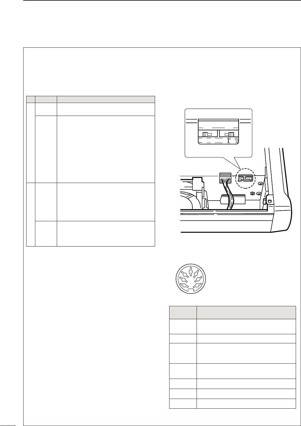
89
15 OPTION UNIT INSTALLATIONS AND SETTINGS
■AT-180 internal switch description
The optional AT-180 has 3 operating conditions for HF
band operation. Select a suitable condition according
to your antenna system.
qRemove the top cover of the AT-180.
wSet the tuner switches to the desired positions ac-
cording to the table below.
•Specifications for the AT-180
• Frequency coverage : 1.9–54 MHz
• Input impedance : 50 Ω
•Maximum input : 120 W
power
•Minimum tuning : 8 W
power
•Matching impedance : 16.7–150 Ω(HF band)
range 20–125 Ω(50 MHz band)
• Tuning accuracy : Less than SWR 1.5:1
• Insertion loss : Less than 1.0 dB
(after tuning)
•Power supply : 13.8 V DC/1 A (supplied from
requirements the transceiver’s ACC socket)
• Dimensions (mm/in) : 167(W)×58.6(H) ×225(D)
69⁄16(W) ×25⁄17(H) ×87⁄8(D)
• Weight : 2.4 kg; 5 lb 4 oz
• Supplied accessories : coaxial cable (1 m),
ACC cable (DIN 13 pins)
•AT-180 inside top cover
•Connector information for ACC(2) socket
S2 S1
DC BA
ACC 2
1
2
3
4
76
5
PIN NO./
NAME DESCRIPTION
q8 V Regulated 8 V output.
(10 mA max.)
wGND Connects to ground.
eSEND
Input/output pin.
Goes to ground when transmitting (20 mA
max). When grounded, transmits.
rBAND Band voltage output.
(Varies with amateur band; 0 to 8.0 V).
tALC ALC output voltage (–4 to 0 V).
yNC No connection.
u13.8V
13.8 V output when power is ON (1 A max).
SW Position
Operation
S1
A
(default)
The tuner operating condition is set by S2
described below.
B
THROUGH INHIBIT
The tuner tunes the antenna even when the
antenna has poor SWR (up to VSWR 3:1
after tuning). In this case, manual tuning is
necessary each time you change the fre-
quency although the tuner automatically
starts tuning when the VSWR is higher than
3:1. This setting is called “through inhibit,”
however, the tuner is set to “through” if the
VSWR is higher than 3:1 after tuning.
S2
C
TUNER SENSITIVE CONDITION
The tuner tunes each time you transmit (ex-
cept SSB mode). Therefore, the lowest
SWR is obtained at any given time.
For SSB mode, the same condition as the
“D” position.
D
(default)
NORMAL CONDITION
The tuner tunes when the SWR is higher
than 1.5:1. Therefore, the tuner activates
only when tuning is necessary.

16
90
SPECIFICATIONS
■General
• Frequency coverage : Receive
30 kHz–60.00000 MHz*
Transmit
1.800– 1.99999 MHz*
3.500– 3.9999 MHz*
7.000– 7.300 MHz*
10.100– 10.150 MHz
14.000– 14.350 MHz
18.068– 18.168 MHz
21.000– 21.450 MHz
24.890– 24.990 MHz
28.000– 29.700 MHz
50.000– 54.000 MHz*
*Depending on version.
• Mode : SSB, CW, AM, FM, RTTY
•Number of memory : 105 (split memory: 99; scan edges: 6)
channels
• Antenna connector : SO-239 /50 Ω
•Usable temperature : –10°C to +60°C (+14°F to +140°F)
range
• Frequency stability : Less than ± 0.5 ppm
(0°C to +50°C; +32°F to +122°F).
•Power supply : 9–15.87 V DC (negative ground)
requirement
• Current drain :
Transmit 2.0 A typ. (TX 5 W at 9.6 V DC)
3.0 A typ. (TX 10 W at 13.8 V DC)
Receive squelched 300 mA typ. (at 9.6 V DC)
max. audio 450 mA typ. (at 9.6 V DC)
1.2 A (at 13.8V DC)
•Dimensions : 167(W) ×58(H) ×200(D) mm,
(projections not included) 69⁄16(W) ×25⁄16(H) ×77⁄8(D) in
• Weight : 2.0 kg (4 lb 4 oz)
• CI-V connector : 2-conductor 3.5 (d) mm (1⁄8˝)
• ACC connector : 13-pin
■Transmitter
• Output power :
SSB, CW, FM, RTTY 0.1–5 W (at 9.6 V DC)
0.1–10 W (at 13.8 V DC)
AM 0.1–2 W (at 9.6 V DC)
0.1–4 W (at 13.8 V DC)
• Modulation system :
SSB Balanced modulation
AM Low level modulation
FM Variable reactance modulation
•Spurious emissions : Less than – 60 dB*
*spurious freq.: below 30 MHz: –50 dB; above 50 MHz: –60 dB
• Carrier suppression : More than 40 dB
• Unwanted sideband : More than 50 dB
•Microphone : 8-pin modular jack (600 Ω)
connector
•KEY connector : 3-conductor 6.35 (d) mm (1⁄4")
■Receiver
• Receive system :
Double-conversion superheterodyne
• Intermediate frequencies:
1st 64.455 MHz
2nd 455 kHz
• Sensitivity at pre-amp ON (typical):
• Squelch sensitivity (threshold; preamp ON) :
SSB/CW/RTTY/AM Less than 5.6 µV
FM Less than 0.32 µV
• Selectivity* (typical) :
SSB/CW More than 2.4 kHz/–6 dB
Less than 4.0 kHz/–60 dB
AM/FM-N More than 9.0 kHz/–6 dB
Less than 20.0 kHz/–50 dB
FM More than 15.0 kHz/–6 dB
Less than 30.0 kHz/–50 dB
*Without optional filter and with mid
band selected.
•Spurious and image rejection ratio:
HF bands More than 70 dB
50 MHz band More than 65 dB (except IF through)
• Audio output power : More than 0.5 W at 10% distortion
with an 8 Ωload (at 9.6 V DC)
More than 1.0 W at 10% distortion
with an 8 Ωload (at 13.8 V DC)
• RIT variable range : ±9.99 kHz max.
• PHONES connector : 3-conductor 3.5 (d) mm (1⁄8˝)/8 Ω
• EXT SP connector : 2-conductor 3.5 (d) mm (1⁄8˝)/8 Ω
■Antenna tuner
• Matching impedance range:
HF bands 16.7 to 150 Ωunbalanced
(Less than VSWR 3:1)
50 MHz band 20 to 125 Ωunbalanced
(Less than VSWR 2.5:1)
• Tuning accuracy : VSWR 1.5:1 or less
• Insertion loss : Less than 1.0 dB (after tuning)
Frequency
range
SSB/CW/RTTY
10 dB S/N
AM
10 dB S/N
FM
12 dB SINAD
0.5–1.8 MHz —13 µV —
1.8–28 MHz 0.16 µV 2.0 µV —
28–29.7 MHz 0.5 µV
50–54 MHz 0.13 µV 1.0 µV 0.25 µV
15
16
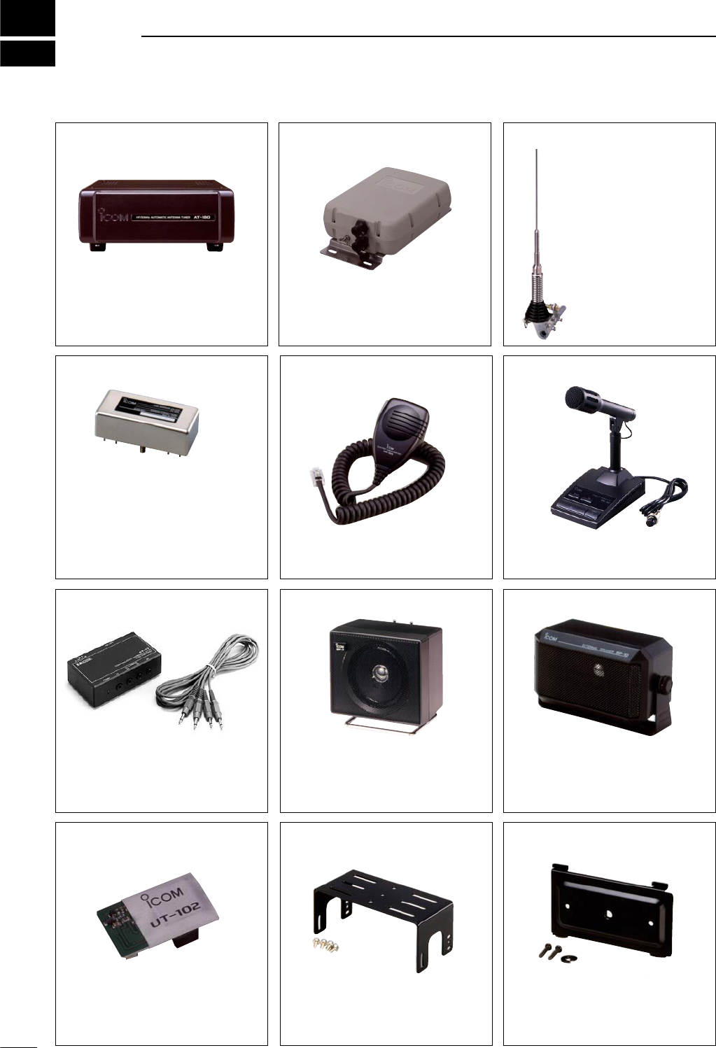
MB-63 MOUNTING BRACKET
Metal plate for attaching the front panel to a
wall or other such flat surface.
17
91
OPTIONS
AT-180 HF/50 MHz AUTOMATIC
ANTENNA TUNER
Fully automatic antenna tuner with preset
memories for each 100 kHz. Unique “auto-
matic tuner on” function is available. See
p. 89 for AT-180 specifications.
HM-103 HAND MICROPHONE
Standard hand microphone.
AH-4 HF AUTOMATIC ANTENNA
TUNER
Specially designed to tune a long wire an-
tenna for portable or mobile HF/50 MHz op-
eration. The “PTT tune” function provides
simple operation.
• Input power rating: 150 W
AH-2b ANTENNA ELEMENT
A 2.5 m long antenna ele-
ment for mobile operation
with the AH-4.
•Frequency coverage
7–54 MHz band with the
AH-4
Optional filters
FL-52A CW/RTTY NARROW FILTER
(500 Hz/–6 dB)
FL-53A CW NARROW FILTER
(250 Hz/–6 dB)
FL-222 SSB NARROW FILTER
(1.8 kHz/–6 dB)
FL-257 SSB WIDE FILTER
(3.3 kHz/–6 dB)
SM-20 DESKTOP MICROPHONE
Includes [UP]/[DOWN] switches and a low
cut function. The OPC-589 is necessary to
use this microphone.
SP-7 EXTERNAL SPEAKER
Compact speaker for base station opera-
tion. Height can be adjusted for your conve-
nience.
• Input impedance: 8 Ω
• Max. input power: 5 W
CT-17 CI-V LEVEL CONVERTER
UNIT
For remote transceiver control using a per-
sonal computer equipped with an RS-232C
port. You can change frequencies, operat-
ing mode, memory channels, etc., via your
computer.
SP-10 EXTERNAL SPEAKER
External speakers suitable for mobile oper-
ation.
SP-12: Slim-type; 8 Ω/3 W
SP-10: Compact-type; 4 Ω/5 W
MB-62
MOBILE MOUNTING BRACKET
Mounts the transceiver main body, with or
without the front panel, inside a vehicle.
UT-102 VOICE SYNTHESIZER UNIT
Announces the receive frequency, mode
and S-meter level in a clear, electronically-
generated voice in English (or Japanese).
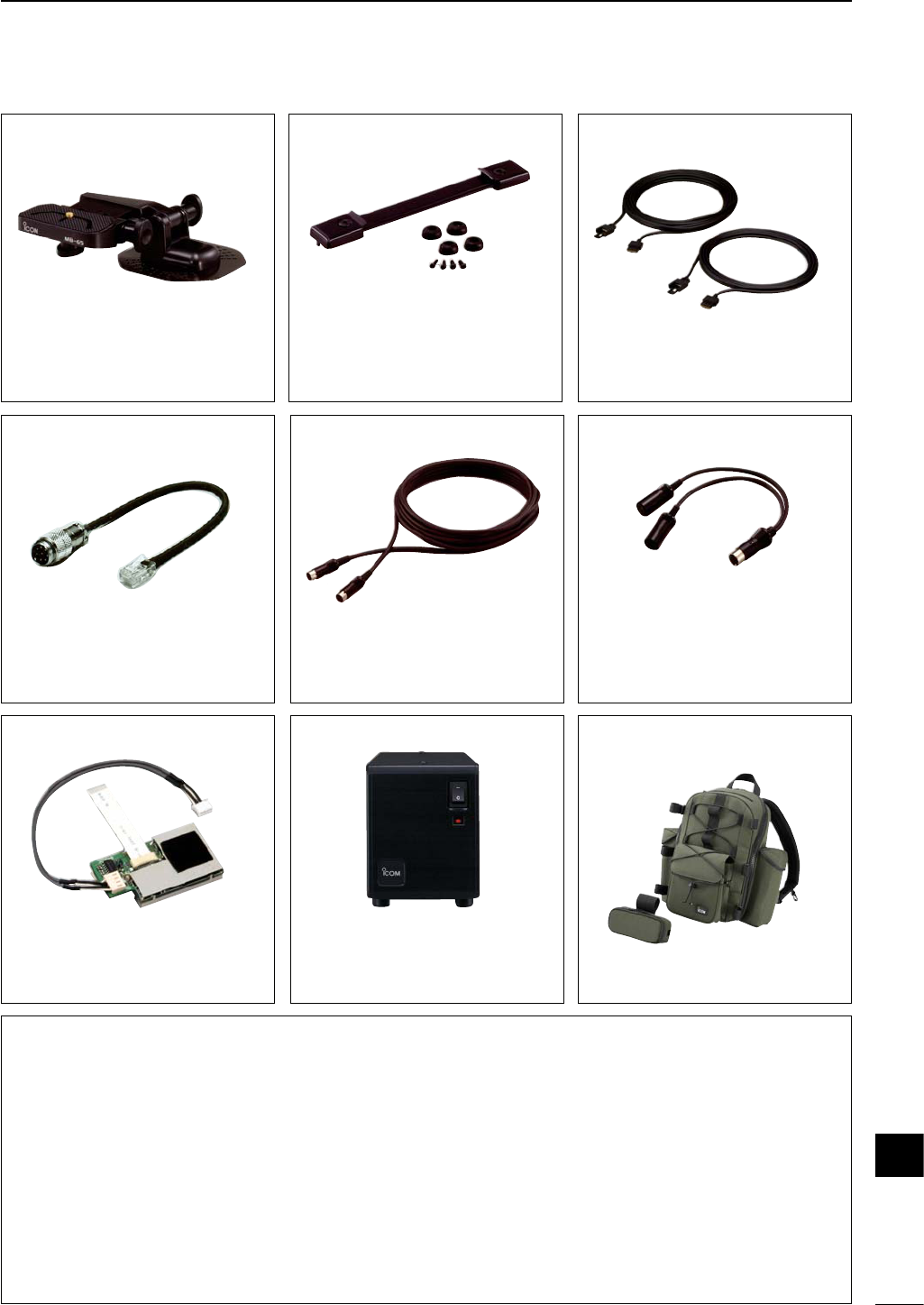
92
17
OPTIONS
BP-228 Ni-Cd BATTERY PACK (9.6 V, 2800 mAh)
Provides outdoor operation (max. output power 5 W).
OPC-1248 DC POWER ADAPTOR CABLE
Provides to connect PS-125. Connects 3-pin DC cable (OPC-1229) to 6-pin connector.
MB-65 MOUNTING BASE
Allows you to conveniently vehicle-mount
the front panel of the IC-703. An MB-63
must be used in combination with the MB-
65.
OPC-598 ACC 13-PIN CABLE
Required when using the AT-180.
MB-72 CARRYING HANDLE
Convenient when carrying the transceiver.
OPC-581/587
SEPARATION CABLE
Provide front panel detached operation for
mobile installations or compact transceiver
operation.
• OPC-581: 3.5 m (11.5 ft)
• OPC-587: 5 m (16.4 ft)
OPC-589
MICROPHONE ADAPTOR CABLE
Conversion between 8-pin modular and 8-
pin metal connector for using a desktop mi-
crophone with the IC-703.
OPC-599 ADAPTOR CABLE
13-pin, ACC connector to 7-pin + 8-pin ACC
connector.
PS-125 DC POWER SUPPLY
Light weight switching regulator power sup-
ply. The OPC-1248 is necessary to use this
power supply.
• Output voltage: 13.8 V
• Max. current drain: 25 A
UT-106 DSP RECEIVER
Provides AF DSP functions such as noise
reduction and auto notch.
Built-in to some versions.
LC-156
MULTI-BAG (with controller case)
17
18
93
MENU GUIDE
CI-V ADDRES
CURRENT IP
Initial set mode
No. Indication Description
1 MAX POWSET
2 PoSAVE MODE
3 SIMPLE MODE
4 MODE SELECT
5 MODE POWSET
6 BEEP
7 BAND BEEP
8 BEEP LEVEL
9 BEEP LIMIT
10 CW NOR SIDE
11 SID-T LEVEL
12 SID-T LIMIT
Max. output power setting
Power save setting
Simple mode setting
Mode availability
Power setting for mode
Confirmation beeps
Band edge beeps
Beep level adjustment
PTT tune function
Tuner switch condition
Packet data speed
CW side tone level
Split offset frequency
Noise blanker in AM mode
No. Indication Description
13 SYNC TUNING
Available memo pads
14 BACK LIGHT
15 KEY LIGHT
16 LIGHT TIMER
18
LED BRIGHT17
19
18
21
22
20
AUTO OFF
SUB DIAL
OPT. FIL
RF/SQL
Scanning speed
23 PEAK HOLD
24 QUICK SPLIT
25 SPLIT LOCK
26 SPL OFFSET
27 SCAN RESUME
28 SCAN SPEED
29 U/D SPEED
30 AM NB
31
A-TUNE STRT
32
PTT TUNE
33
TUNER SW
34
35
36 9600 MODE
37 SPEECH LANG
38 SPEECH SPD
39 S-LVL SPCH
40
41
42
43 CI-V 731
CI-V TRN
CI-V BAUD
CW side tone level limit
Frequency shift setting
Display backlighting
Key/switch backlighting
Light timer setting
LED brightness
Automatic power OFF
Current intercept point
Sub dial setting
Optional filter selection
RF gain/squelch control
Split lock function
Peak meter hold setting
Quick split function
Beep audio level limit
CW carrier point setting
[UP]/[DN] speed
Scan resume condition
PAD CH
PWR ON CHK Power ON check function
Auto tune start function
Voice synthesizer lang.
Voice synthesizer speed
S-meter level speech
CI-V address setting
CI-V data length
CI-V transceive
Data transfer rate
+ power ON Power OFF then ON to exit initial set mode.
MENU
Y
Z
LOCK
*When “3 SIMPLE MODE” is set to ON, box items are undisplayed.
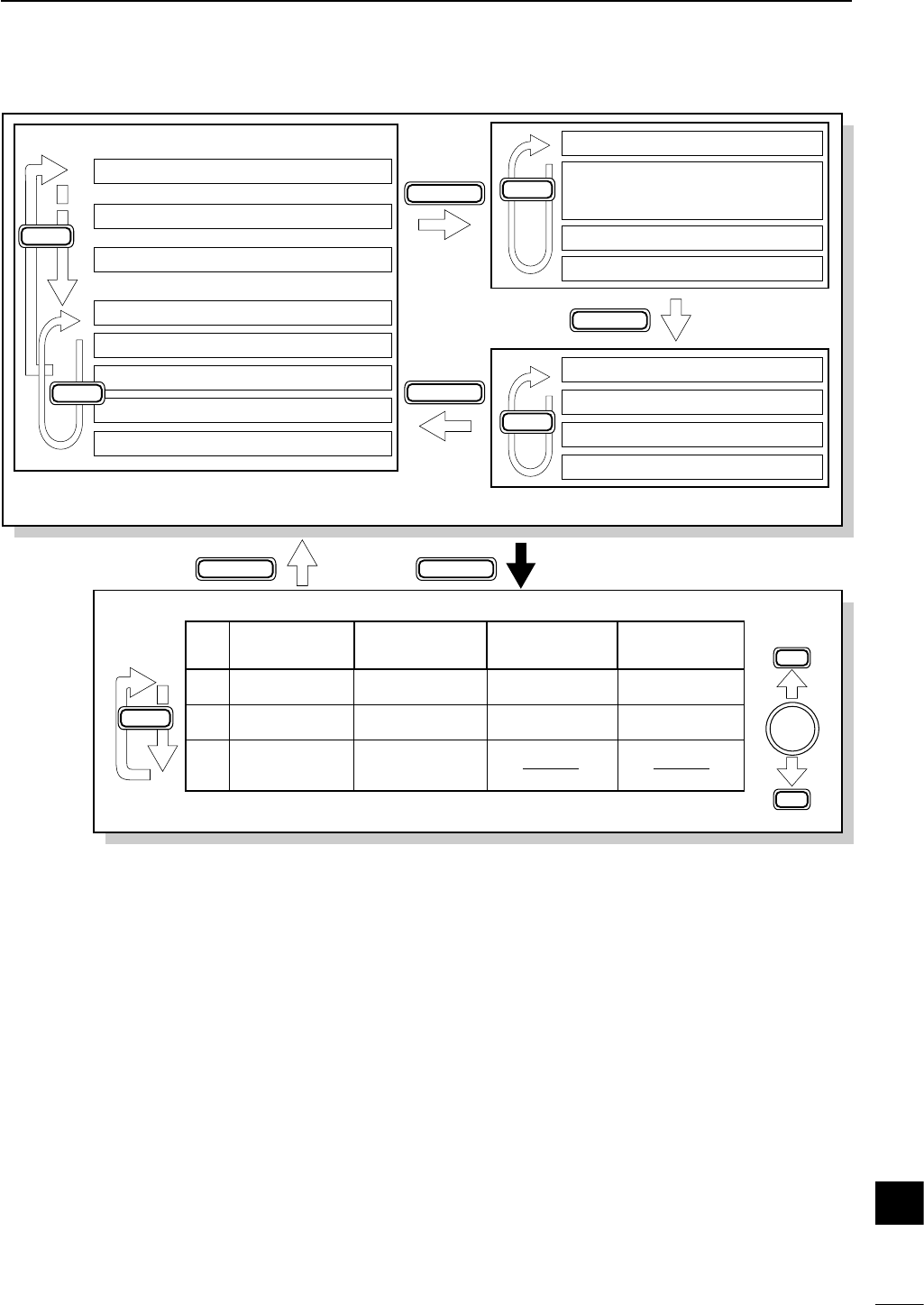
94
18
MENU GUIDE
M1 SPL A/B XFC
M2 MW MCL V/M
M3 FIL NB MET
M4 VOX COM AGC
VOXM4 COM
TON
TON
1/4
1/4
M4 AGC
KEYM4 AGC
S1 MW MPW MPR
S2 SCN PRI
SEL
V/M
Quick set mode
For 1 sec.
(SSB/AM)
(in memory
mode)
(CW)
(RTTY)
(FM)
S3 7 14 21
S4 ANF NR NRL
G1 BAND scope
G2 SWR Graph
G3 TX freq.
G4 Memory name
1/4M4 AGC (SSB-D)
DISPLAY
DISPLAY
DISPLAYDISPLAY
MENU
MENU
Y
Y
M-CH
No.
Q1 RF POWER RF POWER RF POWER
Q2 MIC GAIN KEY SPEED RTTY REV
Q3 CARRIER
Frq*1CW REV
SSB/AM/FM
mode
CW
mode
RTTY
mode
RF POWER
CAR SIDE
SSB-D
mode
*1SSB mode only
MODE
DISPLAY
MENU
MENU
18
19
95
ABOUT CE
INSTALLATION NOTES
For amateur base station installations it is recom-
mended that the forwards clearance in front of the an-
tenna array is calculated relative to the EIRP (Effective
Isotropic Radiated Power). The clearance height below
the antenna array can be determined in most cases
from the RF power at the antenna input terminals.
As different exposure limits have been recommended
for different frequencies, a relative table shows a
guideline for installation considerations.
Below 30 MHz, the recommended limits are specified
in terms of V/m or A/m fields as they are likely to fall
within the near-field region. Similarly, the antenna may
be physically short in terms of electrical length and that
the installation will require some antenna matching de-
vice which can create local, high intensity magnetic
fields. Analysis of such MF installations is best consid-
ered in association with published guidance notes
such as the FCC OET Bulletin 65 Edition 97-01 and its
annexes relative to amateur transmitter installations.
The EC recommended limits are almost identical to the
FCC specified ‘uncontrolled’ limits and tables exist that
show pre-calculated safe distances for different an-
tenna types for different frequency bands. Further in-
formation can be found at http://www.arrl.org/.
• Typical amateur radio installation
Exposure distance assumes that the predominant ra-
diation pattern is forwards and that radiation vertically
downwards is at unity gain (sidelobe suppression is
equal to main lobe gain). This is true of almost every
gain antenna today. Exposed persons are assumed to
be beneath the antenna array and have a typical
height to 1.8 m.
The figures assume the worst case emission of con-
stant carrier.
For the bands 10 MHz and higher the following power
density limits have been recommended:
10–50 MHz 2 W/sq m
EIRP clearance heights by frequency band
1 Watts 2.1 m
10 Watts 2.8 m
25 Watts 3.4 m
100 Watts 5 m
1000 Watts 12 m
Forward clearance, EIRP by frequency band
100 Watts 2 m
1000 Watts 6.5 m
10,000 Watts 20 m
100,000 Watts 65 m
In all cases any possible risk depends on the transmit-
ter being activated for long periods. (actual recom-
mendation limits are specified as an average during 6
minutes) Normally the transmitter is not active for long
periods of time. Some radio licenses will require that a
timer circuit automatically cuts the transmitter after 1–2
minutes etc.
Similarly some types of transmitter, SSB, CW, AM etc.
have a lower ‘average’ output power and the assessed
risk is even lower.
Versions of the IC-703 which display the
“CE” symbol on the serial number seal,
comply with the essential requirements of
the European Radio and Telecommunication
Terminal Directive 1999/5/EC.
This warning symbol indicates that this
equipment operates in non-harmonised fre-
quency bands and/or may be subject to li-
censing conditions in the country of use. Be
sure to check that you have the correct ver-
sion of this radio or the correct programming
of this radio, to comply with national licens-
ing requirement.
96
19
ABOUT CE
DECLARATION
OF CONFORMITY
We Icom Inc. Japan
1-1-32, Kamiminami, Hirano-ku
Osaka 547-0003, Japan
Kind of equipment: HF/
50 MHz ALL MODE TRANSCEIVER
This compliance is based on conformity according to Annex III of the
directive 1999/5/EC using the following harmonised standards:
i) Article 3.1a EN 60950 + A11
ii) Article 3.1b EN 301489-1 and EN 301489-15 (or ETS 300 684)
iii) Article 3.2 EN 301 783-2
iv)
v)
Type-designation: i703
Declare on our sole responsibility that this equipment complies with the
essential requirements of the Radio and Telecommunications Terminal
Equipment Directive, 1999/5/EC, and that any applicable Essential Test
Suite measurements have been performed.
Version (where applicable):
Signature
T. Maebayashi
General Manager
Authorized representative name
Icom (Europe) GmbH
Himmelgeister straße 100
D-40225 Düsseldorf
Place and date of issue
Düsseldorf 14th Mar. 2003
•Version and frequency coverage
Europe (#02, #12)
Receive
0.500–29.999 MHz
50.000–54.000 MHz
Transmit
1.800– 1.999 MHz
3.500– 3.800 MHz
7.000– 7.100 MHz
10.100–10.150 MHz
14.000–14.350 MHz
18.068–18.168 MHz
21.000–21.450 MHz
24.890–24.990 MHz
28.000–29.700 MHz
50.000–52.000 MHz
Italy (#10, #20)
Receive
1.830– 1.850 MHz
3.500– 3.800 MHz
7.000– 7.100 MHz
10.100–10.150 MHz
14.000–14.350 MHz
18.068–18.168 MHz
21.000–21.450 MHz
24.890–24.990 MHz
28.000–29.700 MHz
Transmit
1.830– 1.850 MHz
3.500– 3.800 MHz
7.000– 7.100 MHz
10.100–10.150 MHz
14.000–14.350 MHz
18.068–18.168 MHz
21.000–21.450 MHz
24.890–24.990 MHz
28.000–29.700 MHz
19
1-1-32 Kamiminami, Hirano-ku, Osaka 547-0003 Japan
A-6241H-1EX-q
Printed in Japan
© 2003 Icom Inc.
<Intended Country of Use>
■GER ■
■FRA ■ESP ■SWE
■AUT ■NED ■POR ■DEN
■GBR ■BEL ■ITA ■FIN
■IRL ■LUX ■GRE ■SUI
■NOR
IC-703
#02, #12
(Europe)
HF+50 M
<Intended Country of Use>
■GER ■FRA ■ESP ■SWE
■AUT ■NED ■POR ■DEN
■GBR ■BEL ■ITA ■FIN
■IRL ■LUX ■GRE ■SUI
■NOR
IC-703
#10, #20
(Italy)
HF only