ICOM orporated IC-F11 VHF-FM Handheld Transceiver User Manual
ICOM Incorporated VHF-FM Handheld Transceiver
UserManual.wiki
>
ICOM orporated
>
IC-F11 User Manual
>
User Manual
Contents
1.
User Manual
2.
User Manual Amendment
User Manual
Navigation menu
Upload a User Manual
Namespaces
Wiki Guide
HTML
PDF
Info
Views
User Manual
Discussion / Help
Navigation
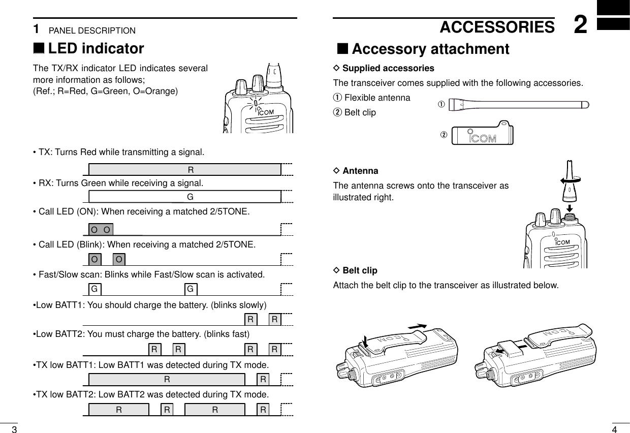
![1 21PANEL DESCRIPTIONPANEL DESCRIPTION1qCHANNEL SELECTOR/SW [CH]• 2CH version: Toggle the CH switch to select CH1 or CH2.• 16CH version: Turn the selector knob to select the pro-grammed operating channel.wVOLUME CONTROL [OFF/VOL]Turns power ON and adjusts the audio level.eDEALER-PROGRAMMABLE KEY [Upper]Can be programmed for one of several functions by your Icomdealer.rPTT SWITCH [PTT]Push and hold to transmit; release to receive.tDEALER-PROGRAMMABLE KEY [Lower]Can be programmed for one of several functions by your Icomdealer.yANTENNA CONNECTORConnects the supplied antenna.uTX/RX INDICATOR LED (see p. 3)• Lights red while transmitting.• Lights green while receiving a signal, or squelch is open.i[SP]/[MIC] JACKConnects optional speaker-microphone.NOTE: Above functions depend on pre-setting.‘‘Switches, controls, keys and connectorsyuSpeakerMicwerti 2CH versionCH1↔CH2 16CH versionCH1 to CH16qSP MICRedUpperLowerMic Up*Mic Down*Mic A*Mic B*DDProgrammable key reference ([Red] depends on version.)*These functions are available when the optional Speaker/Mic. is con-nected.](https://usermanual.wiki/ICOM-orporated/IC-F11.User-Manual/User-Guide-159694-Page-3.png)
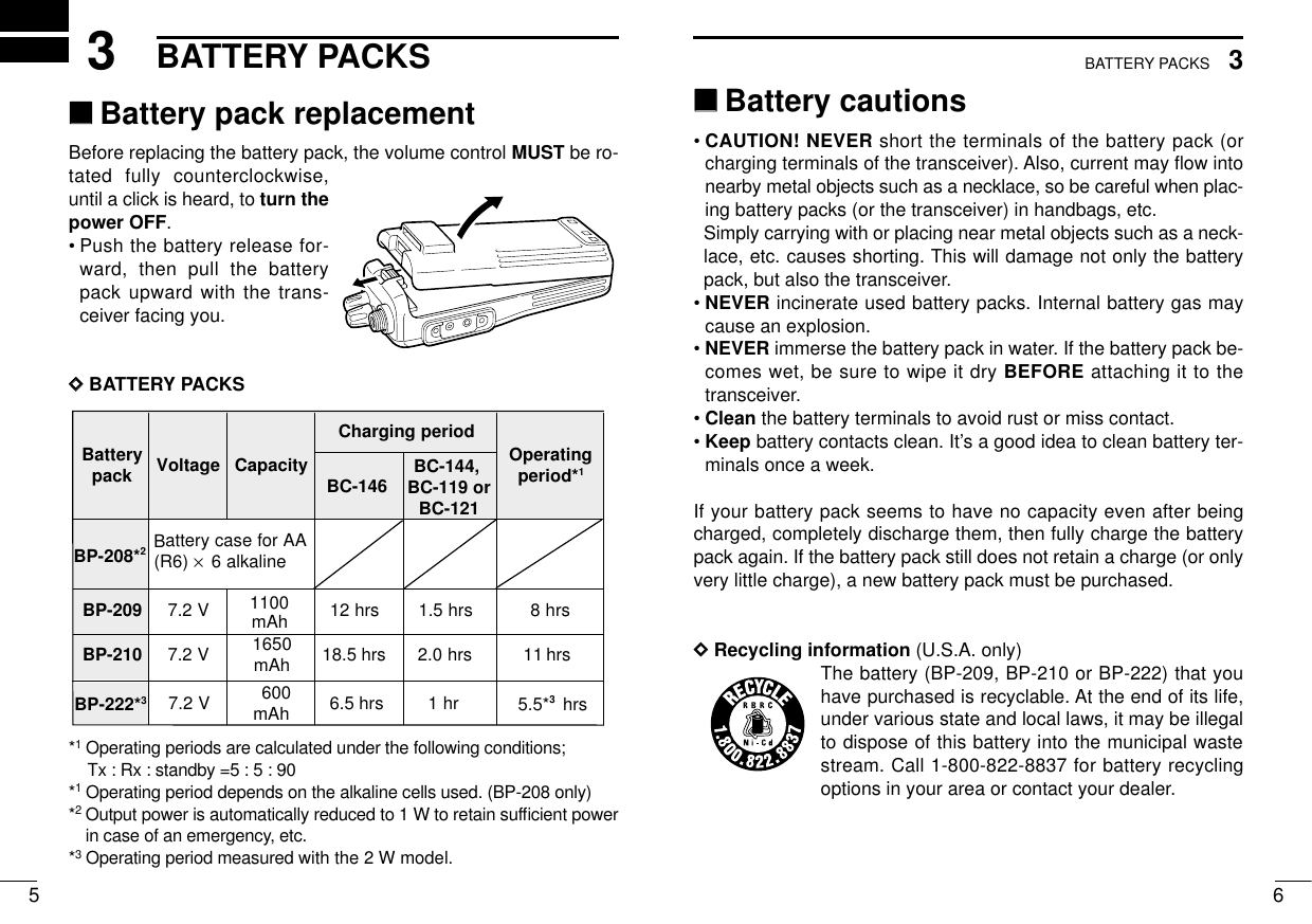
![124PROGRAMMABLE FUNCTIONS‘‘Battery case (Option)When using a BP-208 OPTIONAL BATTERY CASE attached to thetransceiver, install 6 AA (R6) size alkaline batteries as illustratedbelow.NOTE: Output power is automatically reduced to 1 W to retain suffi-cient power in case of an emergency, etc.DDCAUTIONS• Use ALKALINE batteries only.• Make sure all battery cells are the same brand, type and ca-pacity.• Never mix old and new batteries.Either of the above may cause a fire hazard or damage thetransceiver, if ignored.• Never incinerate used battery cells since internal battery gasmay cause them to rupture.• Never expose a detached battery case to water.If the battery case gets wet, be sure to wipe it dry before usingit.113BATTERY PACKS‘‘GeneralIn the following explanations, programmable function names arebracketed, the specific switch used to activate the function dependson programming.DDKEY LOCK FUNCTION1/2This function locks access to all programmable switches (exceptthe switch assigned for the lock function):Lock1: All Key Lock (except Lock key).Lock2: Channel select switch Lock.Push and hold the [Lock1] or [Lock2] switch for 1 sec. to toggle thelock function ON and OFF.• This function may be inhibited on some channels.DDPRIORITY CHANNELThis function is used to select a pre-programmed channel at thepush of a switch.Push the [PrioA], [PrioA(Rewrite)] or [PrioB] switch to select the pri-ority channel.• Priority channel is automatically selected.](https://usermanual.wiki/ICOM-orporated/IC-F11.User-Manual/User-Guide-159694-Page-8.png)
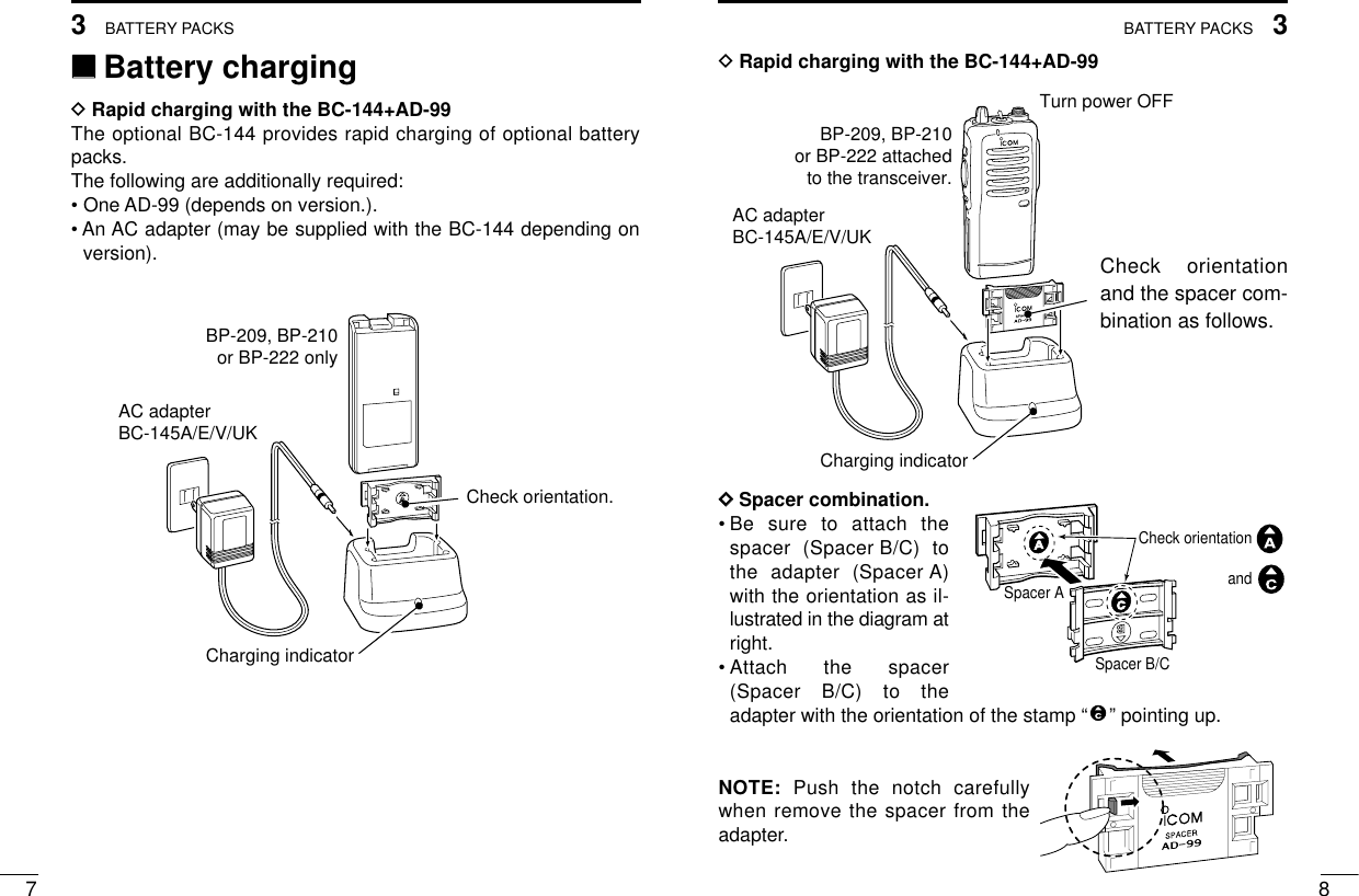
![4PROGRAMMABLE FUNCTIONS134PROGRAMMABLE FUNCTIONS14DDSCAN FUNCTIONThe scan function allows you to search a pre-programmed groupof channels for signals.Push the [Scan] switch to start/stop scan.• Scan pauses on a channel when receiving a signal.• “Lockout SCAN” (pre-programmed list SCAN) or “Priority SCAN”can be pre-programmed.• When the “Power-save function” is activated, the transceiverchecks all pre-programmed channels then returns to the “Power-save function” again.DDHIGH/LOW POWER OUTPUTThis function selects high or low power for a channel.Push the [High/Low] switch to toggle between high and low power.DDMONITOR AUDIBLE FUNCTIONThe monitor function allows you to open the transceiver’s squelchmanually to check whether a channel is busy or not. The trans-ceiver has 2 conditions for receive standby:Audible condition:This condition mutes audio ONLY whenno carrier is present. You can receive (ormonitor) any signals on a channel.• Push and hold the [Moni], switch to se-lect the audible condition.Any audio mute functions are cancelledwhile pushing the [Moni] switch.Inaudible condition:This condition mutes ALL signals exceptthose directed to you. Therefore youshould check a channel’s condition (busyor not) with the monitor function beforetransmitting.• Push the [Moni] switch momentarily toselect the inaudible condition.DDTALK AROUNDThe talk around function changes duplex channels to simplex chan-nels.• Duplex allows you to contact your base station, repeaters, etc.• Simplex allows you to contact other portable transceivers directly(portable-to-portable contact).Push the [Talk Around] switch one or more times to toggle the func-tion ON and OFF.All signals arereceivedOnly signals con-taining the proper tone are received](https://usermanual.wiki/ICOM-orporated/IC-F11.User-Manual/User-Guide-159694-Page-9.png)
![4PROGRAMMABLE FUNCTIONSPROGRAMMABLE FUNCTIONS16152DDDTMF TRANSMISSIONThis function allows you to send a pre-programmed DTMF code tocontrol a repeater, open another transceiver’s squelch, etc.Automatic pre-programmed transmission:Push the [DTMF Autodial] switch to send a DTMF code.DDEMERGENCY FUNCTIONThe emergency function allows you to send your ID quickly andeasily to your Base Station, etc. in case of emergency.Push and hold the [Emergency Single/repeat] switch for 1 sec. toactivate the emergency function.• The transceiver selects a pre-programmed channel, then sendsan emergency signal to your Base Station.• The pre-programmed channel remains selected until a control sig-nal is received from the Base Station, or power is turned OFF.• The emergency call is repeatedly transmitted at pre-programmedintervals.DDMR-CH1, MR-CH2, MR-CH3, MR-CH4This function temporarily allows you to select one of memory CH1to CH4, when you push the [MR-CH1–4] key.DDCODE SQUELCHThis conveniently eliminates unwanted audio and is useful in groupactivities or security related activities where unwanted output canbe a problem. The function is similar to a CTCSS tone squelch.In order to use the above functions, cloning is necessary via a PCusing the optional CS-F11 cloning software. Using this software, thetransceiver’s model, individual RX Code CH, TX Code CH, SpecialTone Link2 (must be ‘E’) in 5Tone screen, 5Tone Signaling Form inMemory-CH screen, Log, RX C-No, Key&Display, Common Au-toReset TimerB, and other settings related to operation can be set.Refer to the HELP file that comes with the CS-F11 CLONING SOFT-WARE for available settings.](https://usermanual.wiki/ICOM-orporated/IC-F11.User-Manual/User-Guide-159694-Page-10.png)
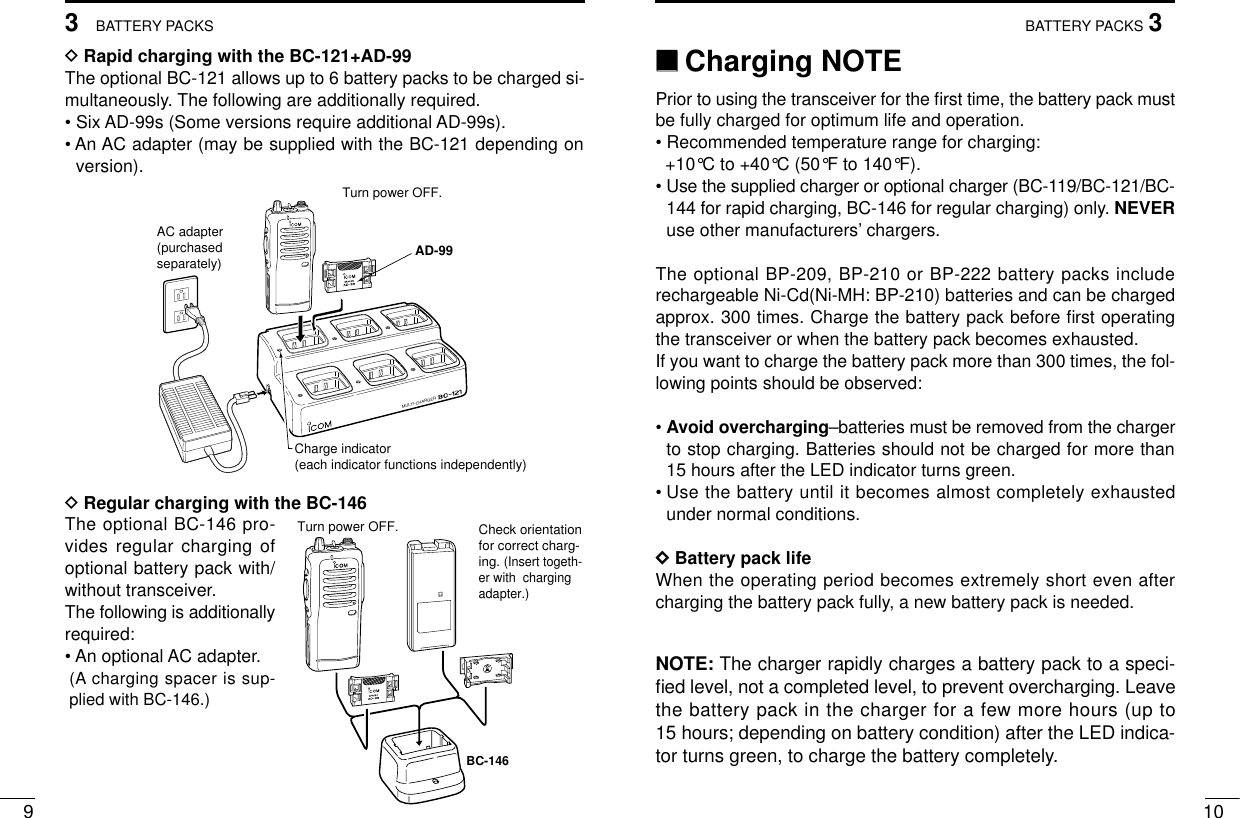
![185CONVENTIONAL OPERATION175CONVENTIONAL OPERATION‘‘Receiving and transmittingNOTE: Transmitting without an antenna may damage the trans-ceiver. See p.4 for antenna attachment.Turn power ON as described on p. 2.Receiving:qSelect a desired channel.wListen for a transmission and adjust [VOL] to a comfortable lis-tening level.• When no transmission is heard, push and hold [Moni] (moni-tor) while adjusting [VOL] (your transceiver may not be pro-grammed with the monitor function).The transceiver is now set to receive desired calls on the selectedchannel.Transmitting:Wait for the channel to become clear to avoid interference.eWhile pushing and holding [PTT], speak into the microphone at anormal voice level.• When a tone signalling system is used, the call procedure de-scribed at right may be necessary.rRelease [PTT] to return to receive.IMPORTANT: To maximize the readability of your transmitted sig-nal, pause a few sec. after pushing [PTT], hold the microphone 10to 15 cm from your mouth and speak at a normal voice level.‘‘Call procedureWhen your system employs tone signalling (excluding CTCSS andDTCS), the call procedure may be necessary prior to voice trans-mission. The tone signalling employed may be a selective callingsystem which allows you to call specific station(s) only and preventunwanted stations from contacting you.qSelect the desired Tx code channel or 5-tone code according toyour System Operator’s instructions.• This may not be necessary depending on programming.wPush the call switch (assigned to one of the dealer programma-ble switches: [Upper] and [Lower], etc.).eAfter transmitting a 5-tone code, the remainder of your commu-nication can be carried out in the normal fashion.Non-selective callingSelective calling](https://usermanual.wiki/ICOM-orporated/IC-F11.User-Manual/User-Guide-159694-Page-11.png)
![206CLONINGCONVENTIONAL OPERATION195‘‘Transmitting notesDDTIME-OUT TIMERAfter continuous transmission for a pre-programmed period, thetime-out timer is activated, causing the transceiver to stop transmit-ting and automatically select receive.DDPENALTY TIMEROnce the time-out timer is activated, transmission is further inhibitedfor a period determined by the penalty timer.‘‘CloningCloning allows you to quickly and easily transfer the programmedcontents from one transceiver to another transceiver; or data fromPC to a transceiver using the optional CS-F11 CLONING SOFT-WARE.DDTransceiver-to-transceiver cloningNOTE: ‘Transceiver-to-transceiver cloning’is available be-tween the same models on 2CH model to 16CH model or theopposite case cannot be cloned.qConnect the optional OPC-474 CLONING CABLE with adapterplugs to the [SP] jack of the master and slave transceivers.•The master transceiver is used to send data to the slave trans-ceiver.wWhile pushing [PTT] and [Upper], turn the transceiver’s poweron to enter cloning mode (master transceiver only–power ONonly for slave transceiver).ePush [PTT] on the master transceiver.•When cloning is finished, a “Beep” tone is emitted two times.NOTE: DO NOT push the [PTT] on the slave transceiver duringcloning. This will cause a cloning error.rWhen cloning is finished, turn power off, then on again to returnto normal operation.DDPC-to-transceiver cloningPlease refer to the HELP file that comes with the CS-F11 CLONINGSOFTWARE.CAUTION: Imprudent cloning operation causes a cloning error.In such a case, memory contents may be lost. Cloning mustthen be repeated.](https://usermanual.wiki/ICOM-orporated/IC-F11.User-Manual/User-Guide-159694-Page-12.png)